

Page 1

omega.com
e-mail: info@omega.com
For latest product manuals:
omegamanual.info
FD6001, FD6002, FD6003
Ultrasonic Flowmeter
with Totalization
MADE IN
Shop online at
User’s Guide
Page 2

Servicing North America:
U.S.A.: One Omega Drive, P.O. Box 4047
ISO 9001 Certified Stamford, CT 06907-0047
TEL: (203) 359-1660 FAX: (203) 359-7700
e-mail: info@omega.com
Canada: 976 Bergar
Laval (Quebec) H7L 5A1, Canada
TEL: (514) 856-6928 FAX: (514) 856-6886
e-mail: info@omega.ca
For immediate technical or application assistance:
U.S.A. and Canada: Sales Service: 1-800-826-6342 / 1-800-TC-OMEGA
®
Customer Service: 1-800-622-2378 / 1-800-622-BEST
®
Engineering Service: 1-800-872-9436 / 1-800-USA-WHEN
®
Mexico: En Espan˜ ol: (001) 203-359-7803 e-mail: espanol@omega.com
FAX: (001) 203-359-7807 info@omega.com.mx
Servicing Europe:
Benelux: Postbus 8034, 1180 LA Amstelveen, The Netherlands
TEL: +31 (0)20 3472121 FAX: +31 (0)20 6434643
Toll Free in Benelux: 0800 0993344
e-mail: sales@omegaeng.nl
Czech Republic: Frystatska 184, 733 01 Karviná, Czech Republic
TEL: +420 (0)59 6311899 FAX: +420 (0)59 6311114
Toll Free: 0800-1-66342 e-mail: info@omegashop.cz
France: 11, rue Jacques Cartier, 78280 Guyancourt, France
TEL: +33 (0)1 61 37 2900 FAX: +33 (0)1 30 57 5427
Toll Free in France: 0800 466 342
e-mail: sales@omega.fr
Germany/Austria: Daimlerstrasse 26, D-75392 Deckenpfronn, Germany
TEL: +49 (0)7056 9398-0 FAX: +49 (0)7056 9398-29
Toll Free in Germany: 0800 639 7678
e-mail: info@omega.de
United Kingdom: One Omega Drive, River Bend Technology Centre
ISO 9002 Certified Northbank, Irlam, Manchester
M44 5BD United Kingdom
TEL: +44 (0)161 777 6611 FAX: +44 (0)161 777 6622
Toll Free in United Kingdom: 0800-488-488
e-mail: sales@omega.co.uk
OMEGAnet®Online Service Internet e-mail
omega.com info@omega.com
It is the policy of OMEGA Engineering, Inc. to comply with all worldwide safety and EMC/EMI
regulations that apply. OMEGA is constantly pursuing certification of its products to the European New
Approach Directives. OMEGA will add the CE mark to every appropriate device upon certification.
The information contained in this document is believed to be correct, but OMEGA accepts no liability for any
errors it contains, and reserves the right to alter specifications without notice.
WARNING: These products are not designed for use in, and should not be used for, human applications.
Page 3

1-1
PART 1 - TABLE OF CONTENTS
Description Pages
Quick Start Installation 1.2-1.3
Operating Theory 1.4
Product Limitations 1.5
Model Number Matrix 1.6
Specifications 1.7
Transducer Installation 2.1-2.5
Pre-Installation Functional Test 3.1-3.2
Transmitter Installation 3.3-3.4
Power Source Jumper Settings 3.5
Electrical Connections 3.5-3.6
Power Up and Configuration 3.7
Keypad Operations 3.8-3.19
Trouble Shooting 3.20-3.21
Appendix
Fluid Sound Speed Conversions
Ductile Iron Pipe Data
Cast Iron Pipe Data
Steel, SS, PVC Pipe Data
FPS to GPM Conversion Chart
Page 4
1-2
This manual contains detailed operating instructions for all
aspects of the FD6000 instruments. The following condensed
instructions are provided to assist the operator in getting
the instrument started up and running as quickly as
possible. This pertains to basic operation only. If specific
instrument features are to be used or if the installer is
unfamiliar with this type of instrument, refer to the
appropriate section in the manual for complete details.
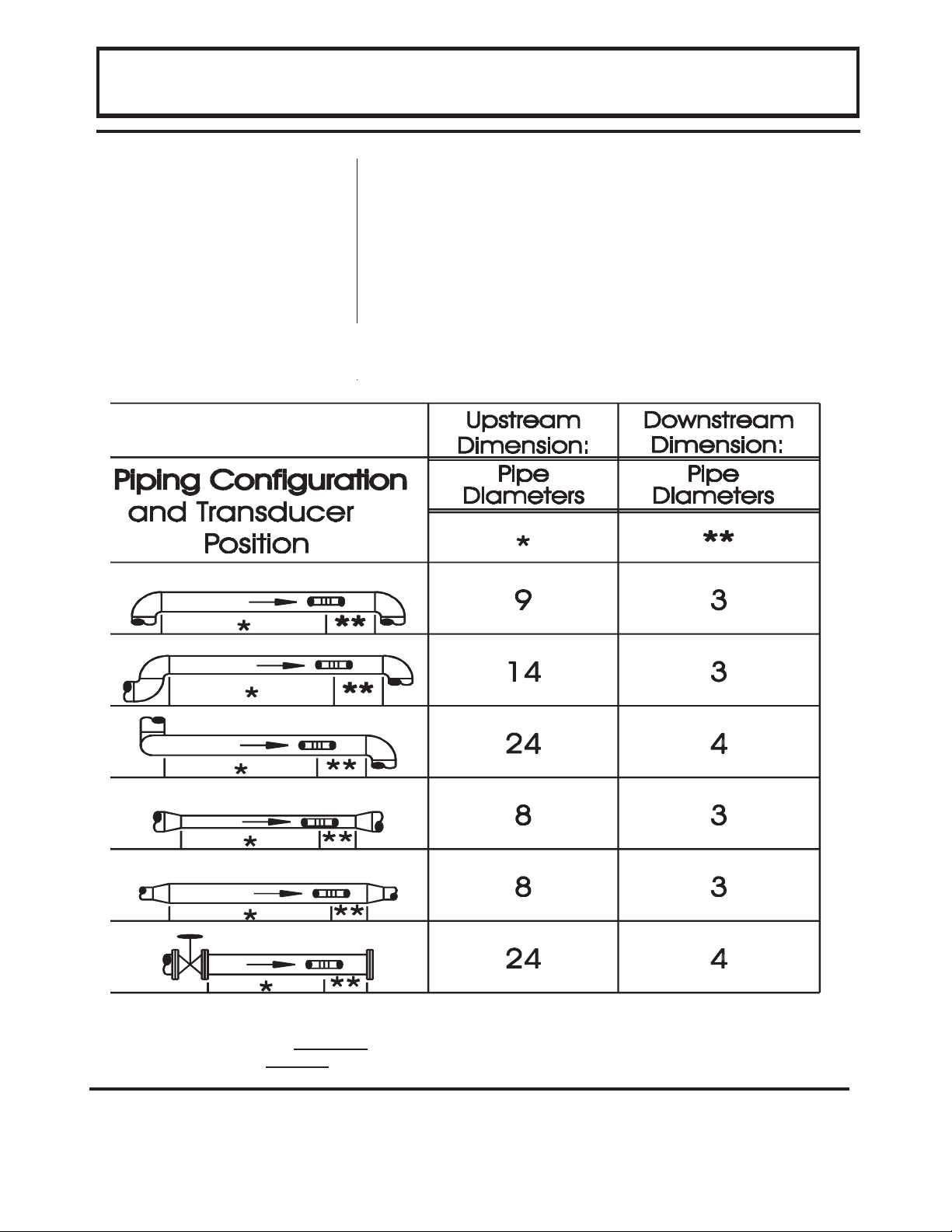
1. TRANSDUCER LOCATION
A. In general, select a mounting location on the piping
system with a minimum of 10 pipe diameters (10 X the
pipe inside diameter) of straight pipe upstream and 5
straight diameters downsteam. See Table 2.1 for
additional configurations.
B. On horizontal pipe, select a position that is between 2
and 4 o’clock on the pipe, with 12 o’clock representing
the top. Installations on vertical pipe should be made
in an area where the flow moves from bottom to top—
ensuring a full pipe of liquid.
2. PIPE PREPARATIO N AND TRANSDUCER
MOUNTING
A. The piping surface, where the transducers are to be
mounted, needs to be clean and dry. Remove loose
scale, rust and paint to ensure satisfactory acoustical
bonds.
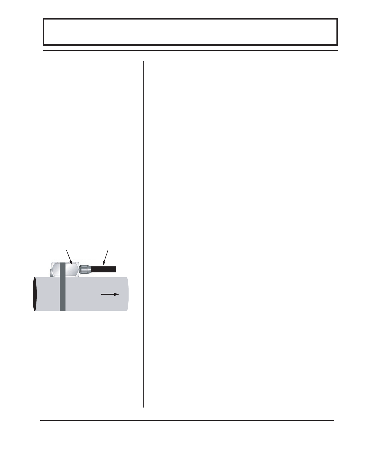
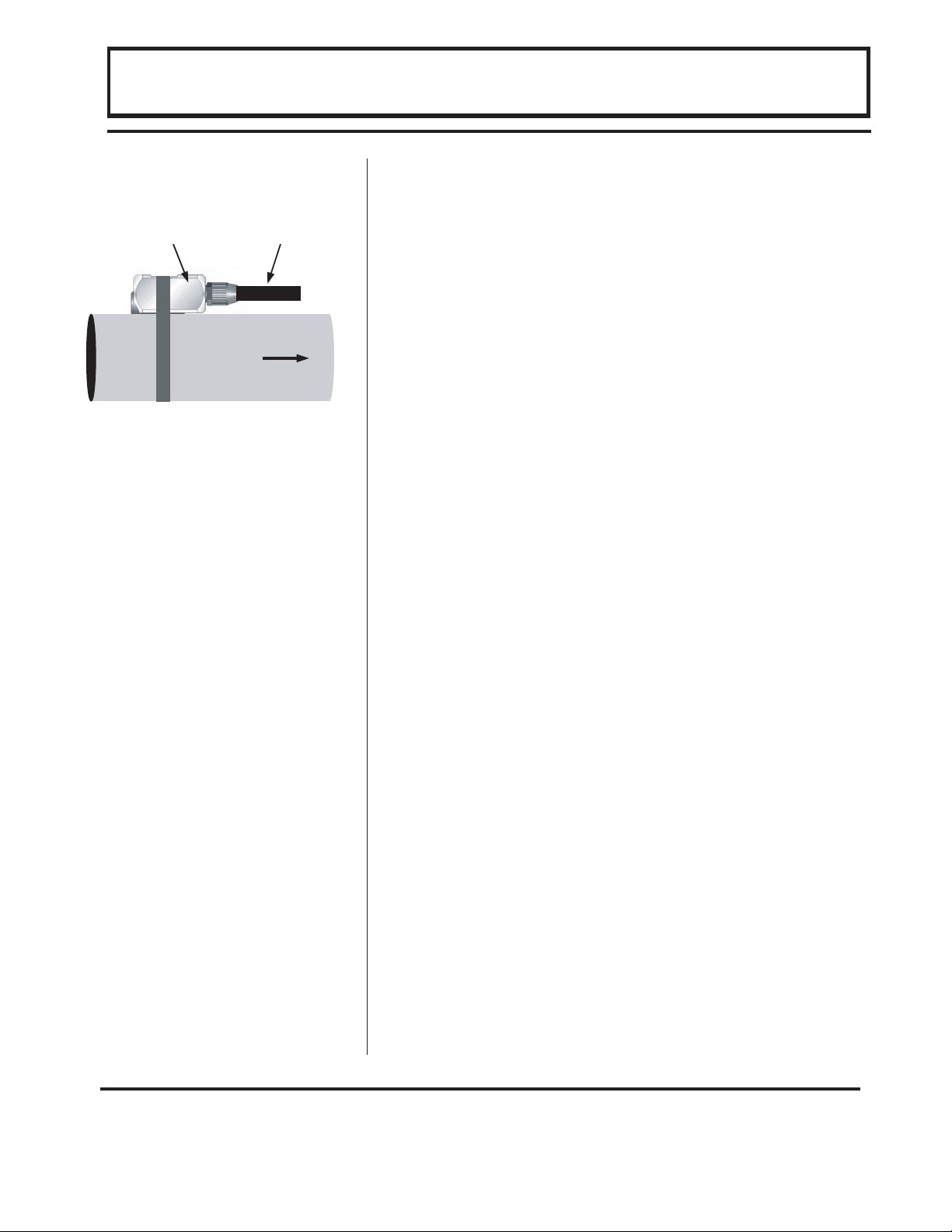
B. Loosely wrap the appropriate length of strap around
the pipe at the location determined in Step 1. Refer to
Figure 1.1 for proper orientation of the transducer. For
greatest accuracy, point the cable of the transducer in
the primary flow direction.
C. Apply a liberal amount of couplant onto the transducer
face. Place the transducer onto the pipe ensuring
square and true placement. If an RTV type of
couplant (requiring curing time) was utilized, allow
sufficient time for curing before applying power to the
instrument or moving the cable.
PART 1 - QUICK START
General
FLOW
Figure 1.1
Top View of Pipe
Transducer Cable
Page 5
1-3
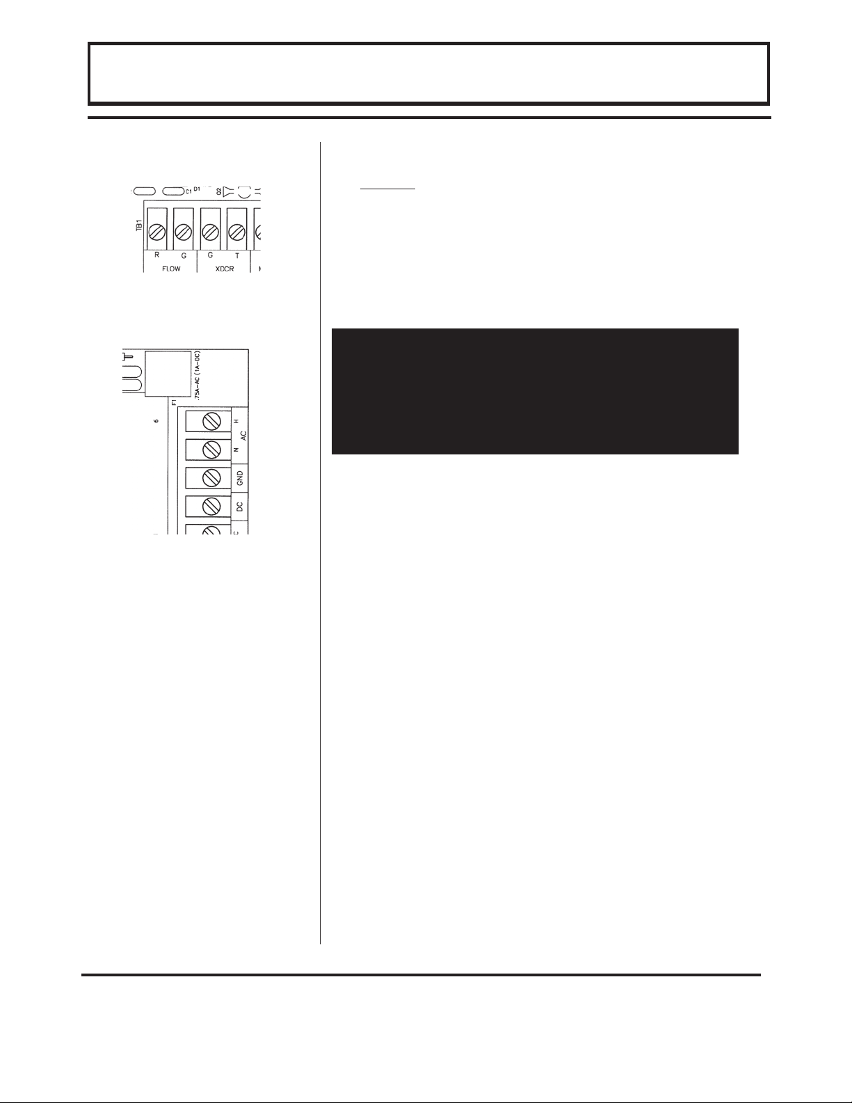
3. TRANSDUCER/POWER CONNECTIONS
A. Do not
attempt to add additional cable to the
transducers.
B. Refer to the DIAGRAMS in Figure 1.2 for proper power
and transducer connections. Verify proper jumper
selections are in place for the power source. See
Figure 3.4.
4. INITIAL SETTINGS AND POWER UP
A. Adjust the GAIN control [R13] to 1/4 turn from full
counter-clockwise rotation.
B. Apply power to the instrument.
C. If the pipe is full of a flowing liquid, the flow meter
signal strength will increase from a zero reading.(press
the
2nd FUNCT
key, then press
SIGNAL STR)
. If the
Signal Strength does not increase to a minimum of
000125 counts, gradually turn the GAIN control [R13]
clockwise until the indication is between 000125 and
000200. (Do not over adjust this setting as ambient
noise can influence readings.)
D. If possible, turn off the flow in the pipe. Verify that
SIGNAL STR. is lower than 000100. If SIGNAL STR.
is greater than 000100, verify that the sensor/
transmitter are not located near electrically noisy
components. (VFDs, inverters, motors, power relays,
etc) Verify that transducer connections are proper
and secure. If the SIGNAL STR. remains greater than
000100, consult the Dynasonics Factory for
assistance. It is possible that the GAIN control [R13] is
set too far clockwise and ambient noise is influencing
the readings. Turn the control counter-clockwise until
the signal strength decreases to below 000070 counts.
E. If the instrument passes steps 4C and 4D, the basic
setup of the instrument is complete.
PART 1 - QUICK START
IMPORTANT!
In order to successfully complete the configuration of
the FD6000 Series flow meter, the transducer must be
mounted on a pipe which is full of a flowing liquid. It
is normal to have a zero reading and no signal
strength indication with empty pipes or zero flow rate.
Figure 1.2
Transducer (top picture)
and Power (bottom picture)
Connections
Page 6

1-4
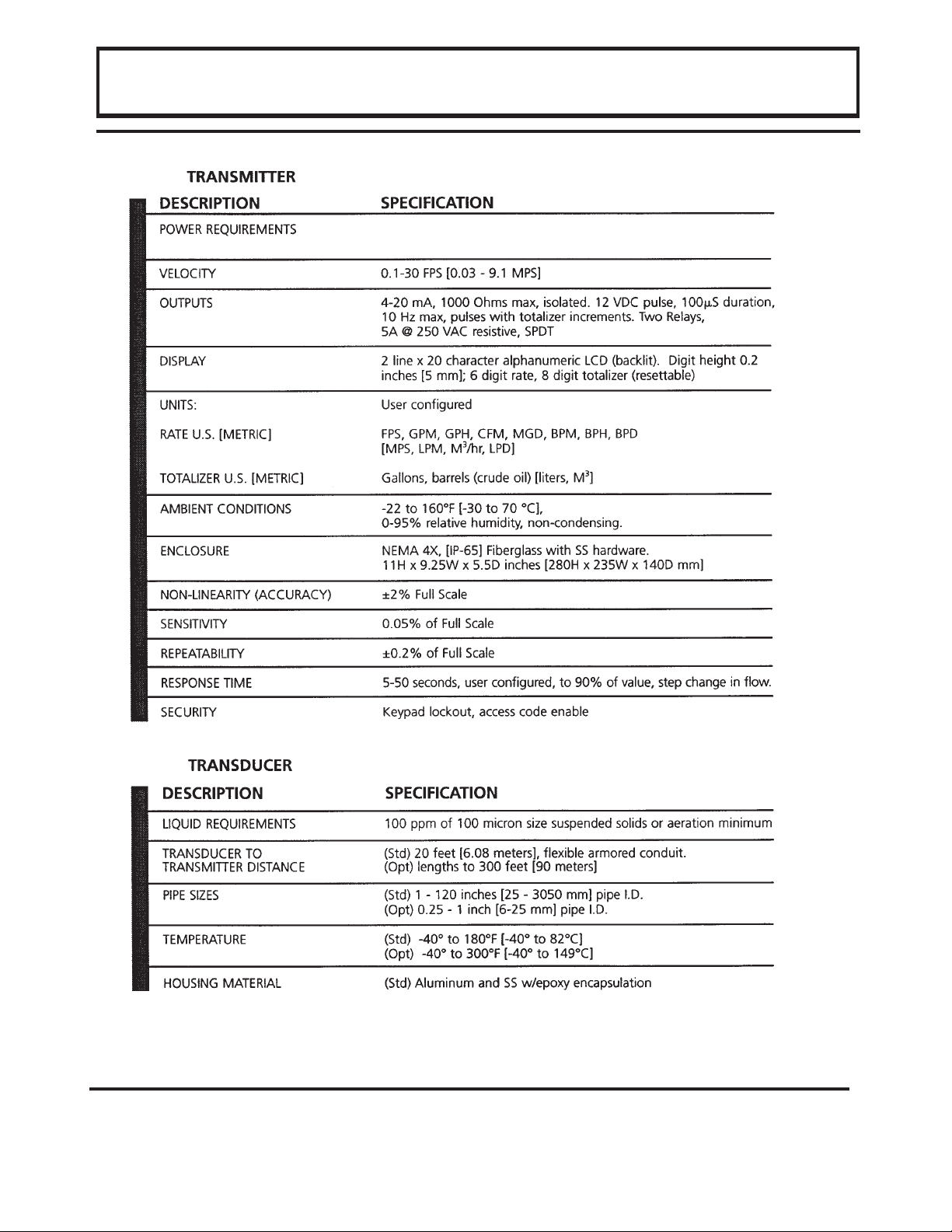
The FD6000 Series flowmeter is designed to
measure the flow of liquids and slurries in full-pipe
closed systems. The transmitter is field configured to
measure flow on a variety of pipes and liquids. The
standard product is typically used on pipe sizes
ranging from 1 - 120 inch [ 25 - 1524 mm ] pipe I.D.
(With the small pipe transducer option, the pipe size
range is 0.25 - 1 inch [ 6 - 25 mm]). A variety of liquid
applications can be accommodated: sewage,
sludges, concrete, mining slurries, dredging, etc.
Because the transducers are non-contacting and
have no moving parts, the flow meter is not affected
by system pressure, fouling or wear. Standard
transducers are rated to 250°F [121°C]. Optional
high temperature transducers are rated to operate to
300°F [149°C].
The basic principle of operation is the measurement
of the frequency shift “Doppler” of a reflected
ultrasonic signal from discontinuity in the flowing
liquid. In theory, these discontinuities can be virtually
any amount of suspended bubbles, solids, or
interfaces caused by turbulent flow. In practice the
degree to which this can be reliably accomplished is a
function of the sensitivity and frequency of the
transducer and associated transmitter. The design
requires greater than 100 PPM of suspended
solids or bubbles over 100 microns in size. The
PART 1 - GENERAL
General
Operating Theory
transducer which generates and receives the
ultrasonic signal supplies the data to the transmitter.
The transmitter processes the signal and provides an
analog and pulse output for velocity indicating and
volumetric totalizing. In addition, the transmitter
contains a signal strength indicator which determines
satisfactory operation.
Page 7

1-5
The flowmeter is typically used as a unidirectional
meter and is most accurate when the transducer is
mounted in the orientation detailed in this manual.
But, the meter will measure flow in both directions —
although flow direction will not be indicated or
totalized properly. The flowmeter will operate from
signals returned from turbulence alone (such as
installation directly at pump discharges or
downstream from elbows and valves); however, it
should be noted that turbulence may vary with flow
rates and result in non-linear results. The
repeatability of the device is not dependent on most
process liquids.
The flowmeter is designed to measure the flow of
liquids and slurries, as long as a small, homogeneous
quantity of entrained air or suspended solids are
present. Without the presence of continuing supply of
air or solids, the transmitted pulses are not reflected
back to the transducer and the indicator will indicate
zero flow.
The signal strength value will indicate a value greater
than 100 counts when a minimum size and
concentration of suspended particles are available for
a reliable flow reading (100 micron and 100 PPM
minimum) and the liquid is moving at least 0.1 FPS
[0.03 MPS]. Most water-based liquids can be
measured from a factory calibrated flowmeter.
However, liquids with a heavy solids level (i.e. over
2% by volume), liquids with sound speeds that vary
from water (see Appendix - Liquid Sound Speed list)
or pipes with liners may have to be field calibrated.
This is done by adjusting the Calibration value on the
keypad to make the indicator agree with a known flow
velocity or a mathematically corrected fluid velocity.
All standard flow meters are calibrated to measure
the flow of a water-based liquid at 25 degrees C. If
the scale range or units need to changed, the process
to do so is covered in detail later in this manual.
PART 1 - GENERAL
Measuring Limits
Page 8

1-6
The FD6000 Series employs modular construction
and provides electrical safety for the operator. The
display face contains voltages no greater than 9 Vdc
and any exposed metal work is electrically connected
to Earth Ground. The display face swings open to
allow access to user connections.
The serial number and complete model number of
your meter is located on the inside of the transmitter
front cover. Should technical assistance be required,
please provide OMEGA’s Customer Service
Department with this information. Email:
flow@omega.com.
PART 1 - GENERAL
Serial Number
Page 9
1-7
PART 1 - GENERAL
(Std) 115 or 230 VAC 50/60 Hz ±10% and 12 VDC. (Opt)
Power consumption less than 12 VA.
Page 10

NOTES
Page 11
2-1
The following list outlines how to install the
transducer for optimal performance, highest reliability
and greatest accuracy:
1. Select a transducer site at least 10 pipe diameters
downstream from bends, or fittings and 5 pipe
diameters upstream. A symmetrical flow pattern is
necessary for accuracy and repeatability over the
PART 2 - TRANSDUCER INSTALLATION
Table 2.1
1
1
The system will provide repeatable measurements on piping systems that do not meet these
requirements, but the accuracy
of these readings may be influenced to various degrees.
Transducer Mounting
Locations
Page 12
2-2
operating range of the meter. Down stream from
pump or orifices, etc., locate at least 20 diameters.
See
Table 2.1
2. On horizontal pipe, select a position that is
between 2 and 4 o’clock on the pipe, with 12
o’clock representing the top. If the transducer is
to be mounted on a vertical pipe, select a section
of pipe where the flow is moving from bottom to
top (flow moving vertically down a pipe tends to
cavitate and provide unreliable operation.)
3. Mount the transducer in the orientation shown in
Figure 2.2. The flow meter will read flow in both
directions, but will be most accurate if the cable is
mounted in the orientation shown—pointing in the
primary flow direction.
4. If totalization of the measured fluid is required, the
pipe must remain full. The meter will read when
the liquid level is greater than the placement of the
transducer, but the volumetric measurement will
be based on a full pipe, so totalization will be
higher than actual.
5. The flowmeter will achieve proper Doppler signals
off of turbulence; however, it should be noted that
turbulence may not be linear with pump speed
changes, nor is the reading necessarily accurate
due to the non-uniformity of turbulence.
6. When a liquid has less than 100 PPM of 100
micron or larger particles, try mounting the
transducer within 12 inches of a pump discharge
or other source of flow turbulence or cavitation. A
reading obtained under these circumstances will
be repeatable, but not necessarily accurate or
linear.
7. It is a good practice to test the flow meter on the
piping system before permanently mounting the
transducer using RTV. Function can be verified
by applying a water soluble lubricant, such as KYJelly, and holding the transducer by hand on the
pipe in the location where the transducer will be
PART 2 - TRANSDUCER INSTALLATION
FLOW
Figure 2.2
Top View of Pipe
Transducer Cable
Page 13

2-3
permanently mounted. Under flowing liquid
conditions, adequate signal is indicated when the
Signal Strength indicates between 000125 and
000200 counts.
For proper operation, there cannot be air voids
between the traducer face and pipe. The space must
be filled with a material which is a good transmitter of
sound energy such as:
SILICONE GREASE: Dow Corning 111 R or
comparable (-100 to +450 F.) The material must be
suitable not to flow at temperature of pipe. Used for
temporary survey installations and portable flow
meters.
SILICONE RUBBER: Dow Corning 732-RTV R.
Excellent for permanent bonding. This adhesive is a
recommended bonding agent and easily removable.
INSTALLATION AND PIPE PREPARATION
The cable from the transducer is provided with
either dual-coaxial cables, flexible nylon conduit or
PVC coated steel conduit with a 1/2” NPT fitting. The
coaxial cable was ordered from the factory at a
specific length
UNDER NO CIRCUMSTANCES
should the coaxial cable be lengthened as this
may de-tune the circuitry and influence
performance
.
Installation of the small-pipe transducers follow the
same procedures as the standard pipe type. The only
difference is that the small pipe transducers utilize an
integral pipe clamping mechanism with two
opposing sensing heads and the standard pipe units
use a stainless steel strap.
PART 2 - TRANSDUCER INSTALLATION
Acoustic Couplant
Types
Small Pipe
Transducers
Page 14

2-4
1. Pipe Preparation:
For permanent silicone adhesive mounting, after
determining the transducer location, some attention
must be given to the pipe condition. Before the
transducer head is bonded to the pipe surface, an
area slightly larger than the flat surface to the
transducer head (black rectangle) must be cleaned to
bare metal. This means the removal of all paint rust,
and scale. Some minor pipe pitting will not cause
problems, as the acoustic couplant will take up the
voids. In the case where plastic pipe is used, remove
all paint and grease so that a smooth, dry surface is
exposed.
2. Transducer Mounting:
The transducer center line is designed to mount
parallel to the pipe center line. The groove in the
transducer body will allow the 1/2” stainless steel
strap that was enclosed with the meter to align the
transducer properly on the pipe.
DO NOT
mount the
transducer on bends, elbows or fittings. Every effort
should be made to mount the transducer parallel to
the axis of the pipe as well as flat on the pipe. The
transducer cable should run in the “down-stream”
direction of liquid flow. See
Figure 2.2
.
In horizontal pipe runs, mount the transducer
between 2 and 4 o’clock from the top—12 o’clock
position; prepare the pipe surface as described.
Finish the surface with some emery paper and then
wipe the surface with trichlorenthylene to thoroughly
degrease the contact surface in a area slightly larger
than the flat surface of the transducer.
For permanent mounting, use a good silicone based
PART 2 - TRANSDUCER INSTALLATION
Intrinsic Safety
Installations
Installations requiring intrinsic safety should refer to
the Appendix drawings covering these applications.
Page 15

2-5
adhesive (Dow-732). Spread a bead of the adhesive
on the flat surface of the transducer face, covering
well. Now spread a bead to the prepared pipe
surface and press the head lightly to the pipe. Let the
adhesive flow enough to fill in all the area beneath the
head. At the same time, clamp (clamp supplied) into
place until the silicone has set up. Taping along the
edges of the head will hold the adhesive in place. A
pad of adhesive must be formed between the
transducer face and the pipe. Ensure that no relative
movement between the transducer and the pipe takes
place during the setup time (about 24 hours). Clamp
transducer only tight enough to hold it in place while
the adhesive is curing. Tighten for mechanical
strength only after 24 hours. Secure the conduit as
well.
3. Temporary Mounting and Spot Checks:
For temporary mounting, clean pipe as described and
use silicone grease as the acoustical coupling
material, holding by hand for spot readings or with a
strap clamp for indefinite periods.
PART 2 - TRANSDUCER INSTALLATION
Page 16

NOTES
Page 17

3-1
PART 3 - PRE-INSTALLATION CHECKOUT
After unpacking, it is recommended to save the shipping
carton and packing materials in case the instrument is
stored or re-shipped. Inspect the equipment and carton
for damage. If there is evidence of shipping damage,
notify the carrier immediately.
The FD6000 Series flowmeter can be checked for basic
functionality using the following Bench Test procedure.
It is recommended that this operation be performed
before permanently installing the system.
Procedure:
1. Open the transmitter cover.
2. Connect the transducer cable connector to the
terminal locations on the lower left corner of the
FD6000 Series main circuit card. See Figure 3.1.
3. Connect supply power to the appropriate terminal
locations on the upper right corner of the main circuit
card. See Figure 3.2. Verify that the power supply
selection jumpers are configured properly—See
Figure 3.4.
4. Apply power.
5. Verify that the display indicates 0.00 FPS (or 0.0 flow
rate of any other unit). If the display does not register
0.0, then press the 2nd FUNCT key, then press
SIGNAL STR. Verify that SIGNAL STR. is lower than
000100. If SIGNAL STR. is greater than 000100,
verify that the sensor/transmitter are not located near
electrically noisy components. (VFDs, inverters,
motors, power relays, etc) Verify that transducer
connections are proper and secure. If the SIGNAL
STR. remains greater than 000100, consult the
Dynasonics Factory for assistance.
6. Press the 2nd FUNCT key to enter SERVICE MODE.
Press the SIGNAL STR key to display SIGNAL STR.
XXXXXX.
7. Rub the face of the transducer lengthwise back and
Unpacking
Functional Test
Figure 3.2
Figure 3.1
Page 18

3-2
forth with your thumb using moderate pressure. The
cycle time should be 1-2 times per second.
8. Verify that signal strength increases with frequency of
the rubbing. Typical increases will range from 20-30
counts.
9. Verify that signal strength decreases when rubbing
ceases.
Bench Test is Complete
PART 3 - PRE-INSTALLATION CHECKOUT
Page 19

3-3
1. Place the transmitter in a location that is:
♦ Where little vibration exist.
♦ Protected from falling corrosive fluids.
♦ Within ambient temperature limits - 22 to 122°F [-30 to
50°C]
♦ Out of direct sunlight. Direct sunlight may increase
temperatures within the transmitter to above maximum
limit.
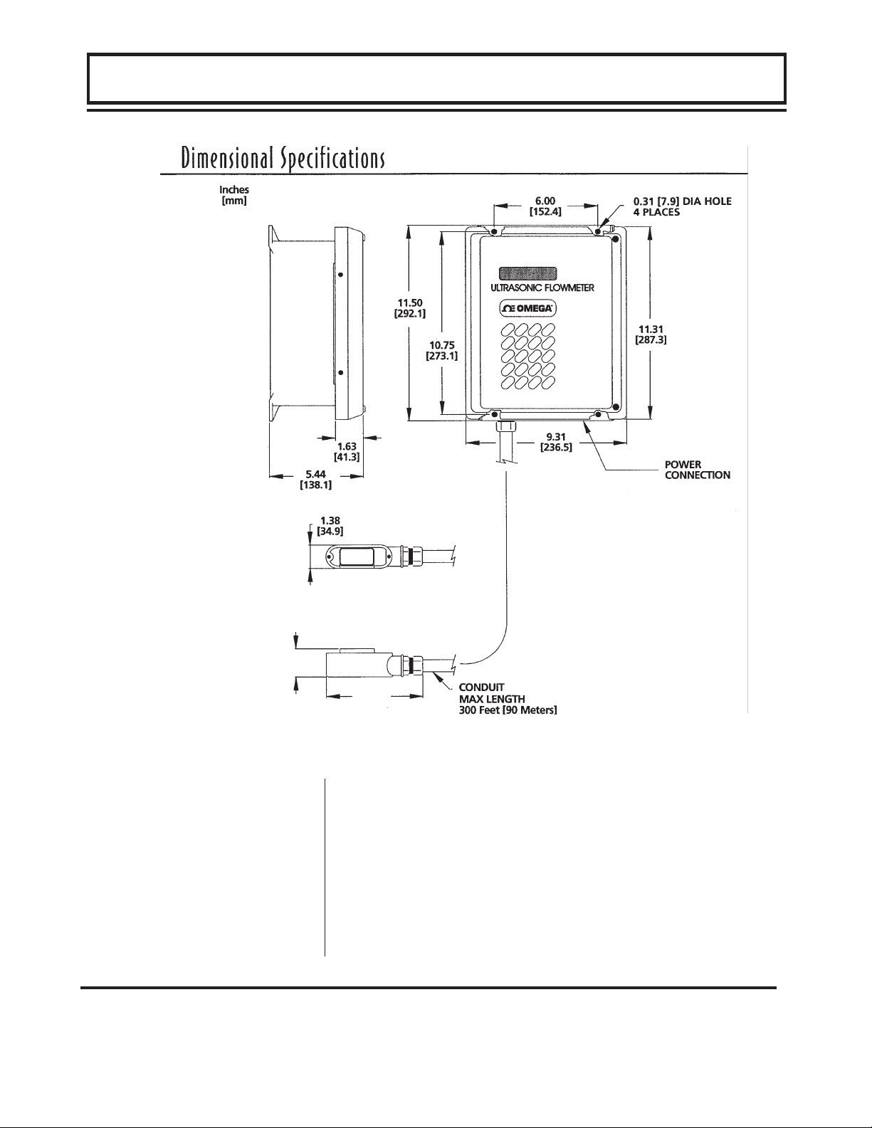
2. Mounting: Refer to Figure 3.3 for enclosure and
mounting dimension details. Ensure that enough room
is available to allow for door swing, maintenance and
conduit entrances. Secure the enclosure to a flat
surface with four appropriate fasteners.
3. Conduit holes. Conduit hubs should be used where
cables enter the enclosure. Holes not used for cable
entry should be sealed with plugs.
NOTE: Use NEMA 4 [ IP65 ] rated fittings and plugs to
maintain the water tight integrity of the enclosure.
Generally, the right conduit hole (viewed from front) is
used for line power; the left conduit hole for transducer
connections.
4. If additional holes are required, (analog outputs, etc.)
drill the appropriate size hole in the enclosure’s
bottom. Use extreme care not to run the drill bit into
the wiring or circuits cards.
To access terminal strips for electronic connectors, loosen
the two screws in the enclosure door and open the door.
PART 2 - ELECTRICAL CONNECTIONS
PART 3 - TRANSMITTER INSTALLATION
Transmitter
Installation
Page 20
3-4
NOTE: The transducer cable carries low level signals.
Do not attempt to add additional cable to the factory
supplied transducer cable.
PART 2 - SERVICE AND MAINTENANCE
PART 3 - TRANSMITTER INSTALLATION
FIGURE 3.3
Important !
FD-5000 Shown
1.45
[36.8]
3.88
[98.5]
Page 21

3-5
The 4-20mA output is proportional to the flow rate
measuring scale and can drive a load of up to 1000 ohms.
The output is isolated from earth ground and circuit low.
Connect the load to the 4-20 mA connection terminals
located on the inside of the enclosure, matching polarity
as indicated.
Line power is connected by supplying power to the
appropriate terminals located inside of the enclosure
Use wiring practices that conform to local codes
(National Electric Code Hand book in the USA).
Use only the standard three wire connection. The ground
terminal grounds the instrument, which is mandatory for
safe operation.
CAUTION: Any other wiring method may be unsafe or
cause improper operation of the instrument.
It is recommended not to run line power with other signal
wires within the same wiring tray or conduit. Verify that
the power supply jumper connections are oriented correctly for the power source being wired. The electronics
can be damaged if improper power is connected or if
jumpers are not installed correctly. The DC input is not
fuse protected. It is recommended that an external fuse
be installed if DC power is selected. The fuse should be a
1A delay action type. See Figure 3.4
Power Source
Jumpers
115 VAC JP8, JP10, JP11
230 VAC JP9, JP11
100 VAC JP7
12 VDC JP3, JP5
24 VDC JP4, JP6
NOTE: This instrument requires clean electrical line
power. Do not connect the meter on a circuit which operates lighting ballasts, motors, solenoids, etc.
PART 2 - SERVICE AND MAINTENANCE
PART 3 - TRANSMITTER INSTALLATION
4-20mA OUTPUT
Power Connections
Figure 3.4
Power Supply Jumper
Selection
Page 22

3-6
1. Guide the transducer terminations through the
transmitter conduit hole located on the left side of the
enclosure. Secure the transducer cable with the
supplied conduit nut.
2. The terminals on the transducer cable are coded with
wire markings. Connect the appropriate wires to the
corresponding screw terminals in the transmitter.
NOTE: The transducer cable carries low level signals.
Do not attempt to add additional cable to the factory
supplied transducer cable.
If additional cable is required contact OMEGA Engineering
to order a transducer with the appropriate length of cable
Cables to 300 feet [90 meters] are available.
NOTE: An additional hole in the transmitter enclosure is
required for outputs. Drill the hole in the the enclosure
bottom taking care not to drive the drill bit into wiring or the
circuit boards with the transmitter.
The CTR pulse output is proportional to the flow rate
measuring scale. This output may be used one of two
ways:
♦
To drive a 12V logic device or electromechanical totalizers.
♦
To drive a low impedance, 12V device. Minimum
resistance 50 ohms.
The pulse output pulses with totalizer increments. The
connections are located on the right side of the signal
processing PCB in the back of the enclosure. The pulse
width is fixed at 50 milli-seconds. CTR “ - ” represents
circuit low. CTR “ + “ represents 12 Vdc pulse output.
PART 3 - TRANSMITTER INSTALLATION
CTR Output
Transducer
Connections
Page 23

3-7
Note: The FD6000 Series flow meter system requires a
full pipe of flowing liquid before a successful startup can
be completed. Do not attempt to make adjustments or
change configurations until a full pipe is verified.
Procedure:
1. Verify that all wiring is properly connected and routed.
2. Apply power.
3. Adjust the GAIN control [R13] to 1/4 turn from full
counter-clockwise rotation.
4. Apply power to the instrument.
5. If the pipe is full of a flowing liquid that contains adequate concentrations of suspended solids, the flow meter signal strength will increase from a zero reading.
(press the 2nd FUNCT key, then press SIGNAL STR).
If the Signal Strength does not increase to a minimum
of 000125 counts, gradually turn the GAIN control
[R13] clockwise until the indication is at between
000125 and 000200. (Do not over adjust this setting
as ambient noise can influence readings.)
6. If possible, turn off the flow in the pipe. Verify that
SIGNAL STR. is lower than 000100. If SIGNAL STR.
is greater than 000100, verify that the sensor/
transmitter are not located near electrically noisy
components. (VFDs, inverters, motors, power relays,
etc) Verify that DT6 transducer connections are proper
and secure. If the SIGNAL STR. remains greater than
000100, consult OMEGA Engineering for
assistance. It is possible that the GAIN control [R13] is
set too far clockwise and ambient noise is influencing
the readings. Turn the control counter-clockwise until
the signal strength decreases to below 000070 counts.
5. If the instrument passes steps 5 and 6, the basic setup
of the instrument is complete.
PART 3 - STARTUP AND CONFIGURATION
Before Starting the
Instrument
Important!
Instrument Startup
It is normal to have low/zero SIGNAL STRENGTH
indication at ZERO flow.
Page 24

3-8
After a successful flow meter installation and startup
(covered in the previous sections of this manual) the FD6000
can be keypad configured to provide select engineering
unit readings of flow and a scaled 4-20mA output.
Configuration inputs are made via the keypad and are
stored by the microprocessor. The entries are retained by
the flow meter’s E
2
PROM memory in the event of power
failure. If fluid velocity readings, FPS or MPS, are the
only required measurement keypad configuration is not
required.
UP/DOWN Arrows
Allow changing of the FD6000 Series configuration
constants. Use the UP arrow to increase constant values
and the DOWN arrow to decrease values. The
arrows can be momentarily pressed to change values
incrementally or held to advance continuously. Constants
outside of the valid range of the unit cannot be
displayed. The scrolling rate at which the values will change
is two tiered. Scrolling will be relatively slow during the first
five seconds of a continuous keypad press; the
scrolling rate will increase after that time to allow rapid
changes of large values.
2
nd
FUNCT
Controls access to the commands located on the lower
half of the keys. After pressing this key the word
SERVICE MODE will appear on the LCD indicator.
ENTER
Records and activates the configuration constant value
that is displayed on the LCD indicator. Can also be used
to return the meter to its run mode.
PART 3 - KEYPAD CONFIGURATION
Page 25

3-9
F1 and F2
Not utilized.
RESET
Caution: Conducts a system reset. All configuration
constants will be lost and the FD6000 will load default values
for all constants.
I.D.
Allows entry of a pipes internal diameter. Internal
diameters must be entered if volumetric flow rates are to
be displayed.
n If a UNITS code for U.S. measurements was made the
I.D. value will be entered in inches. Valid ranges for
this entry are 0.25 to 120.00 inches.
n If a UNITS code for metric measurement was made
the I.D. value will be entered in millimeters. Valid
ranges for this entry are 6 to 3050 millimeters.
The appendices in the back of this manual contain tables
of common pipe sizes and schedules. If the pipe size
does not appear in the table, consult the pipe manufacture
or conduct a physical measurement of the pipe internal
diameter. Errors in the entry of this value can result in
large inaccuracies.
FULL SCALE
Allows entry of the maximum fluid velocity anticipated
within the pipe. This value does not have any bearing on
displayed flow rates or values, but is used to scale the
span value of the 4-20mA analog output. If the analog
output is not going to be utilized set this value to 30.00 if
measuring in U.S. units or 10.00 if measuring in metric
units.
n If a UNITS code for U.S. measurements was made the
FULL SCALE value will be entered in FPS (feet per
PART 3 - KEYPAD CONFIGURATION
Page 26

3-10
second). Valid ranges for this entry are 0.00 to 30.00
FPS. Two useful equations that relate liquid velocity to
volume:
GPM = 2.45 X I.D.
2
X FPS
FPS = ( GPM X 0.408) / I.D.
2
I.D. in inches
n If a UNITS code for metric measurement was made
the I.D. value will be entered in MPS (meters per
second). Valid ranges for this entry are 0 to 10.00
MPS. Two equations that relate liquid velocity to
volume are
LPM = 0.047 X I.D.
2
X MPS
MPS = ( LPM X 21.28) / I.D.
2
I.D. in inches
Note: Attempting to set a FULL SCALE value of less than
0.5 FPS [0.15 MPS] may result in an unstable transmitted
output. If flows are typically lower than this range, the
LOW FLOW FILTERS and higher DAMPing values may
be required.
UNITS
Utilized to set engineering units of measure. There are
twelve different selections possible. The Table 3.1 lists
the entry code number, flow rate unit of measure and
totalizer unit of measure.
Note: After changing the UNITS value, it may be
necessary to change other configuration values
accordingly. For example, FULL SCALE, I.D., HIGH/LOW
ALARM are influenced by the UNITS entry.
Note: Flow already accumulated will not be correctly
compensated for if the UNITS of measure changes.
PART 3 - KEYPAD CONFIGURATION
Page 27

3-11
UNITS Code Flow Rate Totalizer
0
FPS (feet per sec) N/A
1
GPM (gallons per min) GALLONS
2
GPH (gallons per hr) GALLONS
3
MGD (millions of gal
pre day)
GALLONS
4
CFM (ft.3 per min) CF
5
MPS (meters per sec) N/A
6
CMH (m3 per hr) m
3
7
LPM (liters per min) Liters
8
MLD (millions of liters
per day)
Liters
9
BPM (barrels per min) BARRELS
10
BPH (barrels per hr) BARRELS
11
BPD (barrels per day) BARRELS
Table 3.1
PART 3 - KEYPAD CONFIGURATION
Page 28

3-12
HIGH ALARM (Labeled RELAY-1 on the Main PCB)
Controls the set-point of the SPDT relay labeled RELAY-1
on the Main PCB. Enter a liquid velocity
at which a relaycontact action is desired. Relay contacts are utilized for
signaling flow rate conditions that are higher of lower than
a desired set point. If a relay setting is made very close to
a nominal liquid velocity, relay “chatter” ( rapid opening
and closing of the relay ) may result.
n If a UNITS code for U.S. measurements was made the
HIGH ALARM value will be entered in FPS. Valid
ranges for this entry are 0.00 to 30.00 FPS.
n If a UNITS code for metric measurements was made
the HIGH ALARM value will be entered in MPS. Valid
ranges for this entry are 0.00 to 10.00 MPS.
LOW ALARM (Labeled RELAY-2 on the Main PCB)
Controls the set-point of the SPDT relay labeled RELAY-2
on the Main PCB. Enter a liquid velocity at which a relaycontact action is desired. Relay contacts are utilized for
signaling flow rate conditions that are higher of lower than
a desired set point. If a relay setting is made very close to
a nominal liquid velocity, relay “chatter” ( rapid opening
and closing of the relay ) may result.
n If a UNITS code for U.S. measurements was made the
HIGH ALARM value will be entered in FPS. Valid
ranges for this entry are 0.00 to 30.00 FPS.
n If a UNITS code for metric measurements was made
the HIGH ALARM value will be entered in MPS. Valid
ranges for this entry are 0.00 to 10.00 MPS.
TOTAL MULT
Utilized for setting the flow totalizer exponent and
changing the External Counter output. This feature is
useful for accommodating a very large accumulated flow.
The exponent is a “ X 10
n
” multiplier, were “n” can be from
0 (10
0
, X 1 multiplier) to 4 (104, X 10,000 multiplier).
PART 3 - KEYPAD CONFIGURATION
Page 29

3-13
The External Counter output, available at the two
terminals labeled CTR on the Main PCB, is influenced by
the TOTAL MULT value. Since the output is designed to
operate electromechanical accumulators, large flow rates
will require that the TOTAL MULT be set to a value usable
by these types of counters (typically speeds no faster than
3 cps). The following chart tabulates suggested settings
vs. flow ranges:
TOTAL ON/OFF
This key has three functions:
Exponent Multiplier Useable CTR
Range:
GPM or LPM
0
X1 30-600
1
X10 300-6,000
2
X100 3,000-60,000
3
X1,000 30,000-600,000
4
X10,000 300,000-6,000,000
Key press number Operation
First press Stops the internal totalizer/
external CTR and displays
the last value
Second press Resets the internal totalizer
to zero
(continued)
PART 3 - KEYPAD CONFIGURATION
Page 30

3-14
Third press Restarts the internal
totalizer/external CTR
(The internal totalizer starts
from zero.)
(continued)
If inhibiting (pausing) the totalizer is necessary, there are
two methods suggested:
1. Connect and external totalizer to the CTR terminals.
See the section of this manual related to CTR
electrical connections for connection parameters.
2. To inhibit the internal totalizer without resetting the
accumulation, press the TEST key to pause the
accumulation. Press the ENTER key to resume
accumulation.
LOCK ON
To ensure security of the configuration and accumulated
flow, the keypad can be locked. To enable the keyboard
lock out, press LOCK ON key, the display will show
LOCK ON. Press ENTER to return to Run mode. To
turn the lock off, press the LOCK ON key. Use the arrow
keys to set a value of 125. Press the ENTER key. The
display will show LOCK OFF to acknowledge that all
keypad entries can now be made.
CAL
A few factors can influence the readings of a FD6000
flow meter. The CAL entry allows the user to compensate
for flow discrepancies without affecting the factory
calibration. Examples of situations that can cause
reading discrepancies are:
n Operations on liquids with sonic velocity carrying
properties that are different from water. See the table
PART 3 - KEYPAD CONFIGURATION
Page 31

3-15
of correction factors located in the Appendix of this
manual for Liquid Sound Speed and their associated
correction factors.
n Transducer mounted in non-recommended locations.
By applying a CAL value other than 100%, the factorycalibrated readings will be altered by the percentage
entered. This CAL value will be reflected in the display,
4-20mA and CTR outputs and relay settings.
For example, if a reading of 175 GPM is displayed and the
known flow rate is 160 GPM, a CAL value of
160 GPM
x 100 = 91.4%
175 GPM
The FD6000 will not allow decimal values to be entered as
a CAL constant, so round to the nearest whole number; in
this case 91%.
Acceptable input ranges for the CAL constant are 0-255%.
DAMP
In installations where very turbulent or erratic flow is
encountered, increasing the Damping setting can increase
display and output stability. The DAMP setting increases
and decreases the response time of the flow meter display
and outputs. To set the damping time constant, press the
DAMP key. Set a value between 1 and 10, 1 having the
fastest response and 10 having the slowest response.
Press ENTER to complete the configuration.
TEST
The meter contains a test function for verification of the 420mA analog and CTR external counter outputs. To
activate the test function, press the TEST key. Verify that
20mA is flowing in the 4-20mA output and verify that the
CTR output is supplying 50mS pulses. Press ENTER to
exit the test function.
PART 3 - KEYPAD CONFIGURATION
Page 32

3-16
2nd FUNCT - SERVICE MODE
{2nd FUNCT} SIGNAL STR
Displays the raw Doppler signal strength value. This
value will increase as the velocity of the liquid increases.
Typically, a liquid flowing at a velocity greater than 0.2
FPS [0.06 MPS], with adequate suspended solids (100
ppm or 100 micron or larger solids) or aeration, will
produce SIGNAL STR readings of at least 000125 counts.
NOTE: If the liquid is not flowing a low SIGNAL STR
reading is non-conclusive. If a high SIGNAL STR is
indicated at zero flow rate, it indicates that a source of
interference (another ultrasonic instrument, VFD, or poor
electrical ground) may be present. Verify that SIGNAL
STR increases when the flow starts. If it does, increase
the SS CUTOFF setting (see SS CUTOFF).
If SIGNAL STR is lower than 100 counts in a flowing
liquid, one or more of the following steps may need to be
invoked:
1. If the liquid velocity is less than 1 FPS (0.3 MPS) turn
SW-1 “LOW FLOW” switch ON. (This dual DIP switch
is located near the center of the Main PCB.)
2. If SW-1 did not cause an increase in SIGNAL STR to a
level above 100, turn ON SW-2.
3. There may not be adequate reflectors for the Doppler
principle to operate. The transducer can be relocated
to a source of liquid degasification, such as would be
found a 1-3 diameters down stream of a 90-degree
elbow. A surrogate source of aeration can also be
introduced by bleeding a small amount of compressed
air into the line several diameters upstream of
the transducer.
PART 3 - KEYPAD CONFIGURATION
Page 33

3-17
{2nd FUNCT} 4 mA
The 4-20mA output on standard FD6000 Series flow meters
is scaled at zero flow equals 4mA and 20 FPS (6.08 MPS)
equals 20mA. The 4mA key allows fine adjustments to be
made to the “zero” of the 4-20mA output or allows offset to
be placed on the 4-20mA output. To adjust the 4mA
output, an ammeter or reliable reference connection to the
4-20mA output must be present.
Procedure:
1. Either break the present current loop and connect the
ammeter in series (disconnect either wire at the
terminal block labeled 4-20mA on the Main PCB of the
FD6000) or, if this output is not being utilized, connect
the ammeter + to the + terminal and – to the – terminal
of the 4-20mA output.
2. Press the 4mA key.
3. With no flow moving through the pipe, adjust the
setting count using the arrow keys until 4.00mA is
indicated on the ammeter. The typical count value
range for this setting is between 3350 and 3850.
4. Press ENTER to store the value.
5. Re connect the 4-20mA output circuitry as required.
{2
nd
FUNCT} VEL ADC
Press VEL ADC to display the raw analog to digital
converter counts that are being processed by the
microprocessor. This count value will vary linearly with
flow rate from 0000 at zero flow rate to 1024 at maximum
full-scale flow rate. No modifications of this count can be
made, this display is for diagnostic purposes only.
{2
nd
FUNCT} BLANKING
This key is unused.
PART 3 - KEYPAD CONFIGURATION
Page 34
3-18
{2nd FUNCT} 20mA
The 4-20mA output on standard FD6000 flow meters is
scaled at zero flow equals 4mA and 20 FPS (6.08 MPS)
equals 20mA. The 20mA key allows fine adjustments to
be made to the “span” of the 4-20mA output. To adjust
the 20mA output, an ammeter or reliable reference
connection to the 4-20mA output must be present.
Procedure:
1. Either break the present current loop and connect the
ammeter in series (disconnect either wire at the
terminal block labeled 4-20mA on the Main PCB of the
FD6000) or, if this output is not being utilized, connect
the ammeter + to the + terminal and – to the – terminal
of the 4-20mA output.
2. Press the 20mA key.
3. With maximum flow moving through the pipe, adjust
the setting count using the arrow keys until 20.00mA is
indicated on the ammeter. The typical count value
range for this setting is between 1450 and 1950.
4. Press ENTER to store the value.
5. Re connect the 4-20mA output circuitry as required.
{2
nd
FUNCT} SS CUTOFF
This entry represents the signal strength cutoff level (low
velocity cutoff). At flow rates below 0.2 FPS [0.06 MPS]
the readings displayed by the FD6000 are unreliable. By
utilizing the default SS CUTOFF of 100 counts, small
unstable readings at low flow rates will be avoided.
Note: If SS CUTOFF is set to a level higher than the
SIGNAL STR value the meter will not show flow or output
any values.
PART 3 - KEYPAD CONFIGURATION
Page 35

3-19
{2nd FUNCT} INPUT F.S.
This key is used to select a maximum velocity that the
instrument will operate. Choices are 10, 20 and 30 FPS.
It is not recommended to deviate alter this value from
factory settings, as certain spans have been set that
correlate to the set maximum velocity. Consult OMEGA
Engineering for adjustment procedures.
{2
nd
FUNCT} DAC 3
This key is not used.
{2
nd
FUNCT} BACK LIGHT
Toggles the electro-luminescent LCD back lighting ON
and OFF. This type of back lighting has an illumination
half-life of approximately one year. If the instrument is left
unattended for long periods of time, turning the back
lighting OFF can preserve the electro-luminescent panel
and save a small amount of power.
{2
nd
FUNCT} CONTRAST
This setting allows the adjustment of the LCD contrast.
An LCD’s viewing quality is affected by temperature,
ambient lighting, back lighting and viewing angle. Adjust
the contrast level to provide the best contrast possible.
Default count is 50.
PART 3 - KEYPAD CONFIGURATION
Page 36

3-20
PART 3 - TROUBLE SHOOTING
CONDITION POSSIBLE CAUSE
Unit does not turn “ON” when power is
applied
•
Verify that AC power source is live.
•
Test the fuse
•
Verify that proper power supply jumpers
are in place.
FAULT CONDITION is indicated on LCD
indicator
•
Fault conditions can arise from several
causes: electrical surges, short circuits,
open circuits, etc. To clear a “Fault Condition”, press
2nd Function
then press
Re-
set
. Use the arrow keys to change the
Fault code number to “0”. Press
Enter
. If
the meter resumes measuring flow, no
permanent damage was incurred.
•
Ensure that the transducer is properly
mounted to the pipe.
•
Verify that transducer connections are
correct
•
Ensure that the pipe is full of moving
liquid.
•
If SIGNAL STR is less than 000100 counts
and flow rate is greater than 1 FPS [0.3
MPS], adjust GAIN control (R13 on the
Main PCB) till SIGNAL STR reaches at
least 000125 counts.
•
On cleaner liquids, move the transducers
closer to a 90
o
pipe elbow.
•
If GND connection and pipe are at
different potentials, ground FD6000 to
pipe potential.
•
If Variable Frequency Drives are being
utilized, verify that the FD6000 obtains a
flow indication when the pump turns OFF.
If it does, contact OMEGA Engineering.
Page 37

3-21
PART 3 - TROUBLE SHOOTING
Stability of flow readings are
unsatisfactory
• Increase the DAMP constant from keypad.
• Move transducers to a location further
from piping tees, elbows, valves, filters,
Erroneous Reading
• Transducer mounted incorrectly or not
true to the pipe.
• Another local ultrasonic instrument is
operating at about the same frequency
[consult OMEGA Engineering].
• Presence of large amounts of suspended
solids or aeration. Use CAL constant to
compensate.
• Sources of radiated interference are
present. Apply appropriate shielding.
• An electrically noisy power supply is
powering the FD6000. Power the meter
with a circuit that does not power motors.
The display indicates flow, when
true fluid velocity is zero.
• Verify that residual leakage and flow is not
present. [I.e. leaking check valves]
• Verify that GAIN control (R13 on the Main
PCB) is not adjusted too high. With
nominal flow running through the pipe,
adjust GAIN control till the display zeros
with no flow.
Page 38

APPENDIX
Appendix
Fluid Sound Speed Conversions
Pipe Dimension Chart: Ductile Iron
Pipe Dimension Chart: Cast Iron
Pipe Dimension Chart: Steel, SS, PVC
Velocity to Volumetric Conversion Chart
Page 39

Fluid Sound Speeds
Original Date: 10/19/99
Revision: none
Revision Date: none
120.0176921
Doppler
Fluid Specific Gravity Sound Speed Calibration Entry
20 de
g
rees C m/s ft/s relative to 25C water
Acetate, Butyl (n) 1270 4163.9 85
Acetate, Ethyl 0.901 1085 3559.7 72
Acetate, Methyl 0.934 1211 3973.1 81
Acetate, Propyl 1280 4196.7 85
Acetone 0.79 1174 3851.7 78
Alcohol 0.79 1207 3960.0 81
Alcohol, Butyl (n) 0.83 1270 4163.9 85
Alcohol, Ethyl 0.83 1180 3868.9 79
Alcohol, Methyl 0.791 1120 3672.1 75
Alcohol, Propyl (I) 1170 3836.1 78
Alcohol, Propyl (n) 0.78 1222 4009.2 82
Ammonia (35) 0.77 1729 5672.6 115
Anlline (41) 1.02 1639 5377.3 109
Benzene (29,40,41) 0.88 1306 4284.8 87
Benzol, Ethyl 0.867 1338 4389.8 89
Bromine (21) 2.93 889 2916.7 59
n-Butane (2) 0.60 1085 3559.7 72
Butyrate, Ethyl 1170 3836.1 78
Carbon dioxide (26) 1.10 839 2752.6 56
Carbon tetrachloride 1.60 926 3038.1 62
Chloro-benezene 1.11 1273 4176.5 85
Chloroform (47) 1.49 979 3211.9 65
Diethyl ether 0.71 985 3231.6 66
Diethyl Ketone 1310 4295.1 87
Diethylene glycol 1.12 1586 5203.4 106
Ethanol 0.79 1207 3960.0 81
Ethyl alcohol 0.79 1207 3960.0 81
Ether 0.71 985 3231.6 66
Ethyl ether 0.71 985 3231.6 66
Ethylene glycol 1.11 1658 5439.6 111
Freon R12 774.2 2540 52
Gasoline 0.7 1250 4098.4 83
Glycerin 1.26 1904 6246.7 127
Glycol 1.11 1658 5439.6 111
Isobutanol 0.81 1212 3976.4 81
Iso-Butane 1219.8 4002 81
Isopentane (36) 0.62 980 3215.2 65
Isopropanol (46) 0.79 1170 3838.6 78
Isopropyl alcohol (46) 0.79 1170 3838.6 78
Kerosene 0.81 1324 4343.8 88
Linalool 1400 4590.2 93
Page 40

Linseed Oil .925-.939 1770 5803.3 118
Methanol (40,41) 0.79 1076 3530.2 72
Methyl alcohol (40,44) 0.79 1076 3530.2 72
Methylene chloride (3) 1.33 1070 3510.5 71
Methylethyl Ketone 1210 3967.2 81
Motor Oil (SAE 20/30) .88-.935 1487 4875.4 99
Octane (23) 0.70 1172 3845.1 78
Oil, Castor 0.97 1477 4845.8 99
Oil, Diesel 0.80 1250 4101 83
Oil (Lubricating X200) 1530 5019.9 102
Oil (Olive) 0.91 1431 4694.9 96
Oil (Peanut) 0.94 1458 4783.5 97
Paraffin Oil 1420 4655.7 95
Pentane 0.626 1020 3346.5 68
Petroleum 0.876 1290 4229.5 86
1-Propanol (46) 0.78 1222 4009.2 82
Refrigerant 11 (3,4) 1.49 828.3 2717.5 55
Refrigerant 12 (3) 1.52 774.1 2539.7 52
Refrigerant 14 (14) 1.75 875.24 2871.5 58
Refrigerant 21 (3) 1.43 891 2923.2 59
Refrigerant 22 (3) 1.49 893.9 2932.7 60
Refrigerant 113 (3) 1.56 783.7 2571.2 52
Refrigerant 114 (3) 1.46 665.3 2182.7 44
Refrigerant 115 (3) 656.4 2153.5 44
Refrigerant C318 (3) 1.62 574 1883.2 38
Silicone (30 cp) 0.99 990 3248 66
Toluene (16,52) 0.87 1328 4357 89
Transformer Oil 1390 4557.4 93
Trichlorethylene 1050 3442.6 70
1,1,1-Trichloro-ethane 1.33 985 3231.6 66
Turpentine 0.88 1255 4117.5 84
Water, distilled
(
49,50
)
0.996 1498 4914.7 100
Water 0 degrees C 1402 4596.7 94
Water 20 degrees C 1482 4859.0 99
Water 40 degrees C 1529 5013.1 102
Water 60 degrees C 1551 5085.2 103
Water 80 degrees C 1554 5095.1 104
Water 100 degrees C 1543 5059.0 103
Water 120 degrees C 1519 4980.3 101
Water 140 degrees C 1485 4868.9 99
Water 160 degrees C 1440 4721.3 96
Water 180 degrees C 1390 4557.4 93
Water 200 degrees C 1333 4370.5 89
Water, heavy 1 1400 4593 93
Water, sea 1.025 1531 5023 102
Wood Alcohol (40,41) 0.791 1076 3530.2 72
m-Xylene (46) 0.868 1343 4406.2 90
o-Xylene (29,46) 0.897 1331.5 4368.4 89
p-Xylene (46) 1334 4376.8 89
Page 41

Cement Lining
Std./Double
Thickness
ID Wall ID Wall ID Wall ID Wall ID Wall ID Wall ID Wall
3 3.96 3.46 0.25 3.40 0.28 3.34 0.31 3.28 0.34 3.22 0.37 3.14 0.41
4 4.80 4.28 0.26 4.22 0.29 4.16 0.32 4.10 0.35 4.04 0.38 3.93 0.44
6 6.90 6.40 0.25 6.34 0.28 6.28 0.31 6.22 0.34 6.16 0.37 6.10 0.40 6.04 0.43 .123/.250
8 9.05 8.51 0.27 8.45 0.30 8.39 0.33 8.33 0.36 8.27 0.39 8.21 0.42 8.15 0.45
10 11.10 10.32 0.39 10.46 0.32 10.40 0.35 10.34 0.38 10.28 0.41 10.22 0.44 10.16 0.47
12 13.20 12.58 0.31 12.52 0.34 12.46 0.37 12.40 0.40 12.34 0.43 12.28 0.46 12.22 0.49
14 15.30 14.64 0.33 14.58 0.36 14.52 0.39 14.46 0.42 14.40 0.45 14.34 0.48 14.28 0.51
16 17.40 16.72 0.34 16.66 0.37 16.60 0.40 16.54 0.43 16.48 0.46 16.42 0.49 16.36 0.52
18 19.50 18.80 0.35 18.74 0.38 18.68 0.41 18.62 0.44 18.56 0.47 18.50 0.50 18.44 0.53 .1875/.375
20 21.60 20.88 0.36 20.82 0.39 20.76 0.42 20.70 0.45 20.64 0.48 20.58 0.51 20.52 0.54
24 25.80 25.04 0.38 24.98 0.41 24.92 0.44 24.86 0.47 24.80 0.50 24.74 0.53 24.68 0.56
30 32.00 31.22 0.39 31.14 0.43 31.06 0.47 30.98 0.51 30.90 0.55 30.82 0.59 30.74 0.63
36 38.30 37.44 0.43 37.34 0.48 37.06 0.62 37.14 0.58 37.40 0.45 36.94 0.68 36.84 0.73
42 44.50 43.56 0.47 43.44 0.53 43.32 0.59 43.20 0.65 43.08 0.71 42.96 0.77 42.84 0.83 .250/.500
48 50.80 49.78 0.51 49.64 0.58 49.50 0.65 49.36 0.72 49.22 0.79 49.08 0.86 48.94 0.93
54 57.10 55.96 0.57 55.80 0.65 55.64 0.73 55.48 0.81 55.32 0.89 55.16 0.97 55.00 1.05
Class 53
Pipe
Size
(inches)
Outside
Diameter
(inches)
Standard Classes
Ductile Iron Pipe
Class 54 Class 55 Class 56Class 50 Class 51 Class 52
March, 2000
Page 42

Size
(Inches)
O.D.
Inch
I.D.
Inch
Wall
O.D.
Inch
I.D.
Inch
Wall
O.D.
Inch
I.D.
Inch
Wall
O.D.
Inch
I.D.
Inch
Wall
O.D.
Inch
I.D.
Inch
Wall
O.D.
Inch
I.D.
Inch
Wall
O.D.
Inch
I.D.
Inch
Wall
O.D.
Inch
I.D.
Inch
Wall
3 3.80 3.02 0.39 3.96 3.12 0.42 3.96 3.06 0.45 3.96 3.00 0.48
4 4.80 3.96 0.42 5.00 4.10 0.45 5.00 4.04 0.48 5.00 3.96 0.52
6 6.90 6.02 0.44 7.10 6.14 0.48 7.10 6.08 0.51 7.10 6.00 0.55 7.22 6.06 0.58 7.22 6.00 0.61 7.38 6.08 0.65 7.38 6.00 0.69
8 9.05 8.13 0.46 9.05 8.03 0.51 9.30 8.18 0.56 9.30 8.10 0.60 9.42 8.10 0.66 9.42 8.10 0.66 9.60 8.10 0.75 9.60 8.00 0.8
10 11.10 10.10 0.50 11.10 9.96 0.57 11.40 10.16 0.62 11.40 10.04 0.68 11.60 10.12 0.74 11.60 10.00 0.80 11.84 10.12 0.86 11.84 10.00 0.92
12 13.20 12.12 0.54 13.20 11.96 0.62 13.50 12.14 0.68 13.50 12.00 0.75 13.78 12.14 0.82 13.78 12.00 0.89 14.08 12.14 0.97 14.08 12.00 1.04
14 15.30 14.16 0.57 15.30 13.98 0.66 15.65 14.17 0.74 15.65 14.01 0.82 15.98 14.18 0.90 15.98 14.00 0.99 16.32 14.18 1.07 16.32 14.00 1.16
16 17.40 16.20 0.60 17.40 16.00 0.70 17.80 16.20 0.80 17.80 16.02 0.89 18.16 16.20 0.98 18.16 16.00 1.08 18.54 16.18 1.18 18.54 16.00 1.27
18 19.50 18.22 0.64 19.50 18.00 0.75 19.92 18.18 0.87 19.92 18.00 0.96 20.34 18.20 1.07 20.34 18.00 1.17 20.78 18.22 1.28 20.78 18.00 1.39
20 21.60 20.26 0.67 21.60 20.00 0.80 22.06 20.22 0.92 22.06 20.00 1.03 22.54 20.24 1.15 22.54 20.00 1.27 23.02 20.24 1.39 23.02 20.00 1.51
24 25.80 24.28 0.76 25.80 24.02 0.89 26.32 24.22 1.05 26.32 24.00 1.16 26.90 24.28 1.31 26.90 24.00 1.45 27.76 24.26 1.75 27.76 24.00 1.88
30 31.74 29.98 0.88 32.00 29.94 1.03 32.40 30.00 1.20 32.74 30.00 1.37 33.10 30.00 1.55 33.46 30.00 1.73
36 37.96 35.98 0.99 38.30 36.00 1.15 38.70 35.98 1.36 39.16 36.00 1.58 39.60 36.00 1.80 40.04 36.00 2.02
42 44.20 42.00 1.10 44.50 41.94 1.28 45.10 42.02 1.54 45.58 42.02 1.78
48 50.50 47.98 1.26 50.80 47.96 1.42 51.40 47.98 1.71 51.98 48.00 1.99
54 56.66 53.96 1.35 57.10 54.00 1.55 57.80 54.00 1.90 58.40 53.94 2.23
60 62.80 60.02 1.39 63.40 60.06 1.67 64.20 60.20 2.00 64.82 60.06 2.38
72 75.34 72.10 1.62 76.00 72.10 1.95 76.88 72.10 2.39
84 87.54 84.10 1.72 88.54 84.10 2.22
Cast Iron Pipe
Standard Classes
CLASS B CLASS C CLASS D CLASS E CLASS F CLASS G CLASS HCLASS A
March, 2000
Page 43

ID Wall ID Wall ID Wall ID Wall ID Wall ID Wall ID Wall ID Wall ID Wall ID Wall ID Wall ID Wall ID Wall
1 1.315 1.185 0.065 1.097 0.109 1.049 1.049 0.133 0.957 0.179 0.957 0.179 0.815 0.250
1.25 1.660 1.530 0.065 1.442 0.109 1.380 1.380 0.140 1.278 0.191 1.278 0.191 1.160 0.250
1.5 1.900 1.770 0.065 1.682 0.109 1.610 1.610 0.145 1.500 0.200 1.500 0.200 1.338 0.281
2 2.375 2.245 0.065 2.157 0.109 2.067 2.067 0.154 1.939 0.218 1.939 0.218 1.687 0.344
2.5 2.875 2.709 0.083 2.635 0.120 2.469 2.469 0.203 2.323 0.276 2.323 0.276 2.125 0.375
3 3.500 3.334 0.083 3.260 0.120 3.068 3.068 0.216 2.900 0.300 2.900 0.300 2.624 0.438
3.5 4.000 3.834 0.083 3.760 0.120 3.548 3.548 0.226 3.364 0.318 3.364 0.318
4 4.500 4.334 0.083 4.260 0.120 4.026 0.237 4.026 0.237 3.826 0.337 3.826 0.337 3.624 0.438 3.624 0.438 3.438 0.531
5 5.563 5.345 0.109 5.295 0.134 5.047 0.258 5.047 0.258 4.813 0.375 4.813 0.375 4.563 0.500 4.563 0.500 4.313 0.625
6 6.625 6.407 0.109 6.357 0.134 6.065 0.280 6.065 0.280 5.761 0.432 5.761 0.432 5.501 0.562 5.501 0.562 5.187 0.719
8 8.625 8.407 0.109 8.329 0.148 8.125 0.250 8.071 0.277 7.981 0.322 7.981 0.322 7.813 0.406 7.625 0.500 7.625 0.500 7.437 0.594 7.187 0.719 7.187 0.719 6.183 1.221
10 10.750 10.482 0.134 10.42 0.165 10.25 0.250 10.13 0.310 10.02 0.365 10.020 0.365 9.750 0.500 9.750 0.500 9.562 0.594 9.312 0.719 9.062 0.844 9.062 0.844 8.500 1.125
12 12.750 12.420 0.165 12.39 0.180 12.25 0.250 12.09 0.330 12.00 0.375 11.938 0.406 11.626 0.562 11.750 0.500 11.370 0.690 11.060 0.845 10.750 1.000 10.750 1.000 10.120 1.315
14 14.000 13.50 0.250 13.37 0.315 13.25 0.375 13.25 0.375 13.124 0.438 12.814 0.593 13.000 0.500 12.500 0.750 12.310 0.845 11.810 1.095 11.810 1.095 11.180 1.410
16 16.000 15.50 0.250 15.37 0.315 15.25 0.375 15.25 0.375 15.000 0.500 14.688 0.656 15.000 0.500 14.310 0.845 13.930 1.035 13.560 1.220 13.560 1.220 12.810 1.595
18 18.000 17.50 0.250 17.37 0.315 17.12 0.440 17.25 0.375 16.876 0.562 16.564 0.718 17.000 0.500 16.120 0.940 15.680 1.160 15.250 1.375 15.250 1.375 14.430 1.785
20 20.000 19.50 0.250 19.25 0.375 19.25 0.375 19.25 0.375 18.814 0.593 18.376 0.812 19.000 0.500 17.930 1.035 17.430 1.285 17.000 1.500 17.000 1.500 16.060 1.970
24 24.000 23.50 0.250 23.25 0.375 23.25 0.375 23.25 0.375 22.626 0.687 22.126 0.937 23.000 0.500 21.560 1.220 20.930 1.535 20.930 1.535 20.930 1.535 19.310 2.345
30 30.000 29.37 0.315 29.00 0.500 29.00 0.500 29.25 0.375 29.250 0.375 29.000 0.500
36 36.000 35.37 0.315 35.00 0.500 35.00 0.500 35.25 0.375 35.250 0.375 35.000 0.500
42 42.000 41.25 0.375 41.250 0.375 41.000 0.500
48 48.000 47.25 0.375 47.250 0.375 47.000 0.500
Steel, Stainless Steel, P.V.C.
Standard Schedules
SCH.
5
SCH. 10
(LTWALL)
SCH. 20 SCH. 30 STD. SCH. 40 SCH. 60 SCH. 140 SCH. 180
Nominal
Pipe Size
Inches
OUTSIDE
DIAMETER
X STG. SCH. 80 SCH. 100 SCH. 120
March, 2000
Page 44

Nominal
Pipe
(Inches)
I.D.
INCH
1 1.5 2 2.5 3 3.5 4 4.5 5 5.5 6 6.5 7 7.5 8 8.5 9
1 1.05 2.6989 4.0484 5.3978 6.7473 8.097 9.4462 10.796 12.145 13.490 14.844 16.190 17.540 18.890 20.240 21.590 22.941 24.290
1.25 1.38 4.6620 6.9929 9.3239 11.655 13.99 16.317 18.648 20.979 23.310 25.641 27.970 30.300 32.630 34.960 37.300 39.627 41.958
1.5 1.61 6.3454 9.5182 12.691 15.864 19.04 22.209 25.382 28.555 31.730 34.900 38.070 41.250 44.420 47.590 50.760 53.936 57.109
2 2.07 10.489 15.734 20.979 26.224 31.47 36.713 41.958 47.202 52.450 57.692 62.940 68.180 73.430 78.670 83.920 89.160 94.405
2.5 2.47 14.935 22.402 29.870 37.337 44.80 52.272 59.740 67.207 74.670 82.142 89.610 97.080 104.50 112.00 119.50 126.95 134.41
3 3.07 23.072 34.608 46.144 57.680 69.22 80.752 92.288 103.82 115.40 126.90 138.40 150.00 161.50 173.00 184.60 196.11 207.65
3.5 3.55 30.851 46.276 61.702 77.127 92.55 107.98 123.40 138.83 154.30 169.68 185.10 200.50 216.00 231.40 246.80 262.23 277.66
4 4.03 39.758 59.636 79.515 99.394 119.3 139.15 159.03 178.91 198.80 218.67 238.50 258.40 278.30 298.20 318.10 337.94 357.82
5 5.05 62.430 93.645 124.86 156.07 187.3 218.50 249.72 280.93 312.10 343.36 374.60 405.80 437.00 468.20 499.40 530.65 561.87
6 6.06 89.899 134.85 179.80 224.75 269.7 314.65 359.60 404.55 449.50 494.45 539.40 584.30 629.30 674.20 719.20 764.14 809.09
8 7.98 155.89 233.83 311.78 389.72 467.7 545.61 623.56 701.50 779.40 857.39 935.30 1013.0 1091.0 1169.0 1247.0 1325.1 1403.0
10 10.02 245.78 368.67 491.56 614.45 737.3 860.23 983.12 1106.0 1229.0 1351.8 1475.0 1598.0 1720.0 1843.0 1966.0 2089.1 2212.0
12 11.94 348.99 523.49 697.99 872.49 1047.0 1221.5 1396.0 1570.5 1745.0 1919.5 2094.0 2268.0 2443.0 2617.0 2792.0 2966.5 3141.0
14 13.13 422.03 633.04 844.05 1055.1 1266.0 1477.1 1688.1 1899.1 2110.0 2321.1 2532.0 2743.0 2954.0 3165.0 3376.0 3587.2 3798.2
16 15.00 550.80 826.20 1101.6 1377.0 1652.0 1927.8 2203.2 2478.6 2754.0 3029.4 3305.0 3580.0 3856.0 4131.0 4406.0 4681.8 4957.2
FPS TO GPM: GPM = (PIPE ID)² X VELOCITY IN FPS X 2.45 FPS X .3048 = MPS
GPM TO FPS: FPS =
GPM X .0007 = GPD
GPM X 3.7878 = LPM
FPS TO GPM CROSS - REFERENCE (Schedule 40)
GPM
(ID)² X 2.45
Page 45

Nominal
Pipe
(Inches)
I.D.
INCH
1 1.5 2 2.5 3 3.5 4 4.5 5 5.5 6 6.5 7 7.5 8 8.5 9
FPS TO GPM CROSS - REFERENCE (Schedule 40)
18 16.88 697.52 1046.3 1395.0 1743.8 2093.0 2441.3 2790.1 3138.8 3488.0 3836.3 4185.0 4534.0 4883.0 5231.0 5580.0 5928.9 6277.7
20 18.81 866.14 1299.0 1732.0 2165.3 2598.4 3031.5 3464.6 3897.6 4330.7 4763.8 5196.8 5629.9 6063.0 6496.0 6929.1 7362.2 7795.3
24 22.63 1253.7 1880.0 2507.0 3134.1 3761.0 4387.8 5014.6 5641.5 6268.3 6895.1 7522.0 8148.8 8775.6 9402.4 10029 10656 11283
26 25.25 1560.7 2341.0 3121.0 3901.9 4682.2 5462.6 6243.0 7023.4 7803.7 8584.1 9364.5 10145 10925 11706 12486 13266 14047
28 27.25 1817.8 2727.0 3636.0 4544.5 5453.4 6362.3 7271.2 8180.0 9088.9 9997.8 10907 11816 12725 13633 14542 15451 16360
30 29.25 2094.4 3142.0 4189.0 5236.0 6283.2 7330.4 8377.6 9424.9 10472 11519 12566 13614 14661 15708 16755 17803 18850
32 31.25 2390.6 3586.0 4781.0 5976.5 7171.9 8367.2 9562.5 10758 11953 13148 14344 15539 16734 17930 19125 20320 21516
34 33.25 2706.4 4060.0 5413.0 6766.0 8119.2 9472.4 10826 12179 13532 14885 16238 17592 18945 20298 21651 23004 24358
36 35.25 3041.8 4563.0 6084.0 7604.5 9125.4 10646 12167 13688 15209 16730 18251 19772 21292 22813 24334 25855 27376
42 41.25 4165.4 6248.0 8331.0 10414 12496 14579 16662 18744 20827 22910 24992 27075 29158 31241 33323 35406 37489
48 47.99 5637.8 8457.0 11276 14095 16913 19732 22551 25370 28189 31008 33827 36646 39465 42284 45103 47922 50740
54 53.98 7133.1 10700 14266 17833 21399 24966 28532 32099 35665 39232 42798 46365 49931 53498 57065 60631 64198
60 60.09 8839.2 13259 17678 22098 26518 30937 35357 39777 44196 48616 53035 57455 61875 66294 70714 75134 79553
72 72.10 12726 19089 25451 31814 38177 44540 50903 57266 63628 69991 76354 82717 89080 95443 101805 108168 114531
84 84.10 17314 25971 34628 43285 51943 60600 69257 77914 86571 95228 103885 112542 121199 129856 138514 147171 155828
FPS TO GPM: GPM = (PIPE ID)² X VELOCITY IN FPS X 2.45 FPS X .3048 = MPS
GPM TO FPS: FPS =
GPM X .0007 = GPD
GPM X 3.7878 = LPM
(ID)² X 2.45
GPM
Page 46

WARRANTY/DISCLAIMER
OMEGA ENGINEERING, INC. warrants this unit to be free of defects in materials and workmanship for a
period of 13 months from date of purchase. OMEGA’s WARRANTY adds an additional one (1) month
grace period to the normal one (1) year product warranty to cover handling and shipping time. This
ensures that OMEGA’s customers receive maximum coverage on each product.
If the unit malfunctions, it must be returned to the factory for evaluation. OMEGA’s Customer Service
Department will issue an Authorized Return (AR) number immediately upon phone or written request.
Upon examination by OMEGA, if the unit is found to be defective, it will be repaired or replaced at no
charge. OMEGA’s WARRANTY does not apply to defects resulting from any action of the purchaser,
including but not limited to mishandling, improper interfacing, operation outside of design limits,
improper repair, or unauthorized modification. This WARRANTY is VOID if the unit shows evidence of
having been tampered with or shows evidence of having been damaged as a result of excessive corrosion;
or current, heat, moisture or vibration; improper specification; misapplication; misuse or other operating
conditions outside of OMEGA’s control. Components in which wear is not warranted, include but are not
limited to contact points, fuses, and triacs.
OMEGA is pleased to offer suggestions on the use of its various products. However,
OMEGA neither assumes responsibility for any omissions or errors nor assumes liability for any
damages that result from the use of its products in accordance with information provided by
OMEGA, either verbal or written. OMEGA warrants only that the parts manufactured by the
company will be as specified and free of defects. OMEGA MAKES NO OTHER WARRANTIES OR
REPRESENTATIONS OF ANY KIND WHATSOEVER, EXPRESSED OR IMPLIED, EXCEPT THAT OF
TITLE, AND ALL IMPLIED WARRANTIES INCLUDING ANY WARRANTY OF MERCHANTABILITY
AND FITNESS FOR A PARTICULAR PURPOSE ARE HEREBY DISCLAIMED. LIMITATION OF
LIABILITY: The remedies of purchaser set forth herein are exclusive, and the total liability of
OMEGA with respect to this order, whether based on contract, warranty, negligence,
indemnification, strict liability or otherwise, shall not exceed the purchase price of the
component upon which liability is based. In no event shall OMEGA be liable for
consequential, incidental or special damages.
CONDITIONS: Equipment sold by OMEGA is not intended to be used, nor shall it be used: (1) as a “Basic
Component” under 10 CFR 21 (NRC), used in or with any nuclear installation or activity; or (2) in medical
applications or used on humans. Should any Product(s) be used in or with any nuclear installation or
activity, medical application, used on humans, or misused in any way, OMEGA assumes no responsibility
as set forth in our basic WARRANTY/DISCLAIMER language, and, additionally, purchaser will indemnify
OMEGA and hold OMEGA harmless from any liability or damage whatsoever arising out of the use of the
Product(s) in such a manner.
RETURN REQUESTS/INQUIRIES
Direct all warranty and repair requests/inquiries to the OMEGA Customer Service Department. BEFORE
RETURNING ANY PRODUCT(S) TO OMEGA, PURCHASER MUST OBTAIN AN AUTHORIZED RETURN
(AR) NUMBER FROM OMEGA’S CUSTOMER SERVICE DEPARTMENT (IN ORDER TO AVOID
PROCESSING DELAYS). The assigned AR number should then be marked on the outside of the return
package and on any correspondence.
The purchaser is responsible for shipping charges, freight, insurance and proper packaging to prevent
breakage in transit.
FOR W
ARRANTY RETURNS, please have the
following information available BEFORE
contacting OMEGA:
1. Purchase Order number under which the product
was PURCHASED,
2. Model and serial number of the product under
warranty, and
3. Repair instructions and/or specific problems
relative to the product.
FOR NON-WARRANTY REPAIRS,
consult OMEGA
for current repair charges. Have the following
information available BEFORE contacting OMEGA:
1. Purchase Order number to cover the COST
of the repair,
2. Model and serial number of the product, and
3. Repair instructions and/or specific problems
relative to the product.
OMEGA’s policy is to make running changes, not model changes, whenever an improvement is possible. This affords
our customers the latest in technology and engineering.
OMEGA is a registered trademark of OMEGA ENGINEERING, INC.
© Copyright 2005 OMEGA ENGINEERING, INC. All rights reserved. This document may not be copied, photocopied,
reproduced, translated, or reduced to any electronic medium or machine-readable form, in whole or in part, without the
prior written consent of OMEGA ENGINEERING, INC.
Page 47

M4176/0605
Where Do I Find Everything I Need for
Process Measurement and Control?
OMEGA…Of Course!
Shop online at omega.com
TEMPERATURE
䡺⻬
Thermocouple, RTD & Thermistor Probes, Connectors, Panels & Assemblies
䡺⻬
Wire: Thermocouple, RTD & Thermistor
䡺⻬
Calibrators & Ice Point References
䡺⻬
Recorders, Controllers & Process Monitors
䡺⻬
Infrared Pyrometers
PRESSURE, STRAIN AND FORCE
䡺⻬
Transducers & Strain Gages
䡺⻬
Load Cells & Pressure Gages
䡺⻬
Displacement Transducers
䡺⻬
Instrumentation & Accessories
FLOW/LEVEL
䡺⻬
Rotameters, Gas Mass Flowmeters & Flow Computers
䡺⻬
Air Velocity Indicators
䡺⻬
Turbine/Paddlewheel Systems
䡺⻬
Totalizers & Batch Controllers
pH/CONDUCTIVITY
䡺⻬
pH Electrodes, Testers & Accessories
䡺⻬
Benchtop/Laboratory Meters
䡺⻬
Controllers, Calibrators, Simulators & Pumps
䡺⻬
Industrial pH & Conductivity Equipment
DATA ACQUISITION
䡺⻬
Data Acquisition & Engineering Software
䡺⻬
Communications-Based Acquisition Systems
䡺⻬
Plug-in Cards for Apple, IBM & Compatibles
䡺⻬
Datalogging Systems
䡺⻬
Recorders, Printers & Plotters
HEATERS
䡺⻬
Heating Cable
䡺⻬
Cartridge & Strip Heaters
䡺⻬
Immersion & Band Heaters
䡺⻬
Flexible Heaters
䡺⻬
Laboratory Heaters
ENVIRONMENTAL
MONITORING AND CONTROL
䡺⻬
Metering & Control Instrumentation
䡺⻬
Refractometers
䡺⻬
Pumps & Tubing
䡺⻬
Air, Soil & Water Monitors
䡺⻬
Industrial Water & Wastewater Treatment
䡺⻬
pH, Conductivity & Dissolved Oxygen Instruments
 Loading...