

Page 1

MAINTENANCE MANUAL
USG-400
ISSUE 1
2011/11
Page 2

Page 3

USG-400
CONTENTS
Chapter 1 : Product Outline................................................................... 1-1
1 Outline ................................................................................................................................. 1-2
2 Features............................................................................................................................... 1-2
3 Limitations........................................................................................................................... 1-3
4 System chart....................................................................................................................... 1-4
Chapter 2 : Specifications..................................................................... 2-1
1 Specifications ..................................................................................................................... 2-2
Chapter 3 : Installation and Connection............................................... 3-1
1 Installation workflow.......................................................................................................... 3-2
2 Installation of the ultrasonic generator............................................................................ 3-3
3 Connection of compatible electrosurgical generator
(when using the THUNDERBEAT) .................................................................................... 3-4
4 Connection to power supply (Ultrasonic Generator) .....................................................3-11
5 Automatic mist & smoke evacuation system/function
(When using the compatible high flow insufflation unit)............................................. 3-12
6 Connection of footswitch (optional)............................................................................... 3-15
7 Connection of the THUNDERBEAT and/or SONICBEAT
(various options available).............................................................................................. 3-17
Chapter 4 : Care, Storage, and Disposal.............................................. 4-1
1 Care...................................................................................................................................... 4-2
2 Storage ................................................................................................................................ 4-3
3 Disposal............................................................................................................................... 4-3
Chapter 5 : Inspection............................................................................ 5-1
1 Verification workflow.......................................................................................................... 5-2
2 Power verification............................................................................................................... 5-3
3 Verification of communication cable connection between compatible electrosurgical
generator and ultrasonic generator (when using the THUNDERBEAT)........................ 5-6
4 Verification of touch-screen and push buttons............................................................... 5-7
5 Verification of the THUNDERBEAT and/ or SONICBEAT............................................... 5-10
6 Verification of footswitch connection............................................................................. 5-13
7 Verification of the high-frequency(RF bipolar) output
(when using the THUNDERBEAT) .................................................................................. 5-13
8 Verification of the alarm system...................................................................................... 5-17
9 Procedure after verification............................................................................................. 5-19
10 Inspection check sheet .................................................................................................... 5-20
Chapter 6 : Safety check........................................................................ 6-1
1 Check procedures ..............................................................................................................6-2
1-1 Grounding Resistance confirmation...................................................................................... 6-2
1-2 Ground leakage current confirmation.................................................................................... 6-2
1-3 Enclosure leakage current confirmation............................................................................... 6-2
1-4 Patient leakage current confirmation..................................................................................... 6-3
1-5 Leakage current criteria .......................................................................................................... 6-5
2 Check Card.......................................................................................................................... 6-6
ISSUE1 1 Contents
Page 4

USG-400
Chapter 7: Block Diagram ..................................................................... 7-1
1 Block Diagram..................................................................................................................... 7-2
Chapter 8 : Troubleshooting ................................................................. 8-1
1 Troubleshooting.................................................................................................................. 8-2
2 Error screen ........................................................................................................................ 8-3
3 Troubleshooting guide....................................................................................................... 8-3
3 Returning the ultrasonic generator for repair................................................................ 8-22
Contents 2 ISSUE1
Page 5

USG-400
INTRODUCTION
Introduction
Repair and maintenance of this product requires highly specialized knowledge and techniques. We
recommend that you contact an Olympus service center in your area if a problem develops with the
product.
If repairs or modifications are made by personnel not authorized by Olympus, the warranty is void, and
Olympus shall not be liable for damage that occurs to or as a result of use of the modified product.
Applicable Unit
USG-400
Copyright
Unauthorized reproduction or distribution in part or in whole is prohibited.
Trademarks
OLYMPUS is a registered trademark of Olympus Corporation.
INTRODUCTION 1 ISSUE1
Page 6

Page 7

USG-400
Chapter 1 : Product Outline
1 Outline................................................................................................1-2
2 Features.............................................................................................1-2
3 Limitations.........................................................................................1-3
4 System chart......................................................................................1-4
ISSUE1 1-1 Product Outline
Page 8

USG-400
1 Outline
(1) Purpose of Use
The THUNDERBEAT instruments are intended for use of coagulation/cutting of tissue and sea ling/cutting of
vessels in combination with the ultrasonic generator, the electrosurgical generator and the THUNDERBEAT
transducer that are specified by Olympus in general surgery (including endscopic and microscopic surgery)
(2) Allowable Combinations
This product can be used in combination with the products listed in system diagram.
2 Features
(1) This product, which has two handpiece connectors, enables dissection and coaguration of body tiss ues by
plugging the handpieces int their corresponding handpiece connectors.
THUNDERBEAT Connector (Handpiece Connector 1) : SEAL & CUT output / SEAL output
SONICBEAT Connector (Handpiece Connector 2) : Ultrasonic output
(2) PLL resonance tracking control and constant current control enable stable ultrasonicvibration.
(3) Various setting are shown on the touch-panel LCD. They can be changed on the display.
(4) All the devices have their own hand switches that enable ON/OFF control of output.
(5) All the devices have their own foot switches that enable ON/OFF control of output.
(6) This product has the interface for output interlock and the output can be controlled.
Combination of ESG-400 and MAJ-1871 enable use of combine output.
Combination of UHI-2 or UHI-3 and MAJ-1871 or MAJ-1872 and MAJ-1873 enable use of automatic
fume control function.
Combination of UHI-4 and MAJ-1871 or MAJ-1872 enable use of automatic fume contril function.
(7) This product has the “setting selection” function that allows the user to arrange , and various settings
saved in advance can be called us easily.
(8) Its interface for PC communication enable use of the followingfunctions.(User unidentified)
Software Upgrading
Download and Upload of log data.
(9) The language shown on LCD can be selected from eight languages.
(10) As a result of introduction of the corporate product design, its desigh is consistent with the desighs of
products in hte same generation.
(11) This product can be connected to ENDOALPHA-3 system.
Product Outline 1-2 ISSUE1
Page 9

USG-400
3 Limitations
(1) Use this product under the supervision of a doctor at a medical facility.
(2) Do not use this product in combination with the products other than those designated by Olympus.
(3) This product shoul d be used, transported or stored in the following environment.
1)Usage environment
Ambient temperature 10 - 40°C
Relative humidity 30 - 85%
Atmospheric pressure 70 - 106kPa
Altitude 3000m or less
(Do not use this product in the combustible atmosphere)
2)Transportation/storage environment
Ambient temperature -25 - 70°C
Relative humidity 10 - 90%
Atmospheric pressure 70 - 106kPa
(4) Power source
1)Voltage, current
J type 100V, 3A
A type 120V, 3A
E type 220 - 240V, 1.5A
2)Frequency 50/60Hz
3)Voltage variation Within ±10%
4)Frequency variation Within ±1Hz
ISSUE1 1-3 Product Outline
Page 10
USG-400
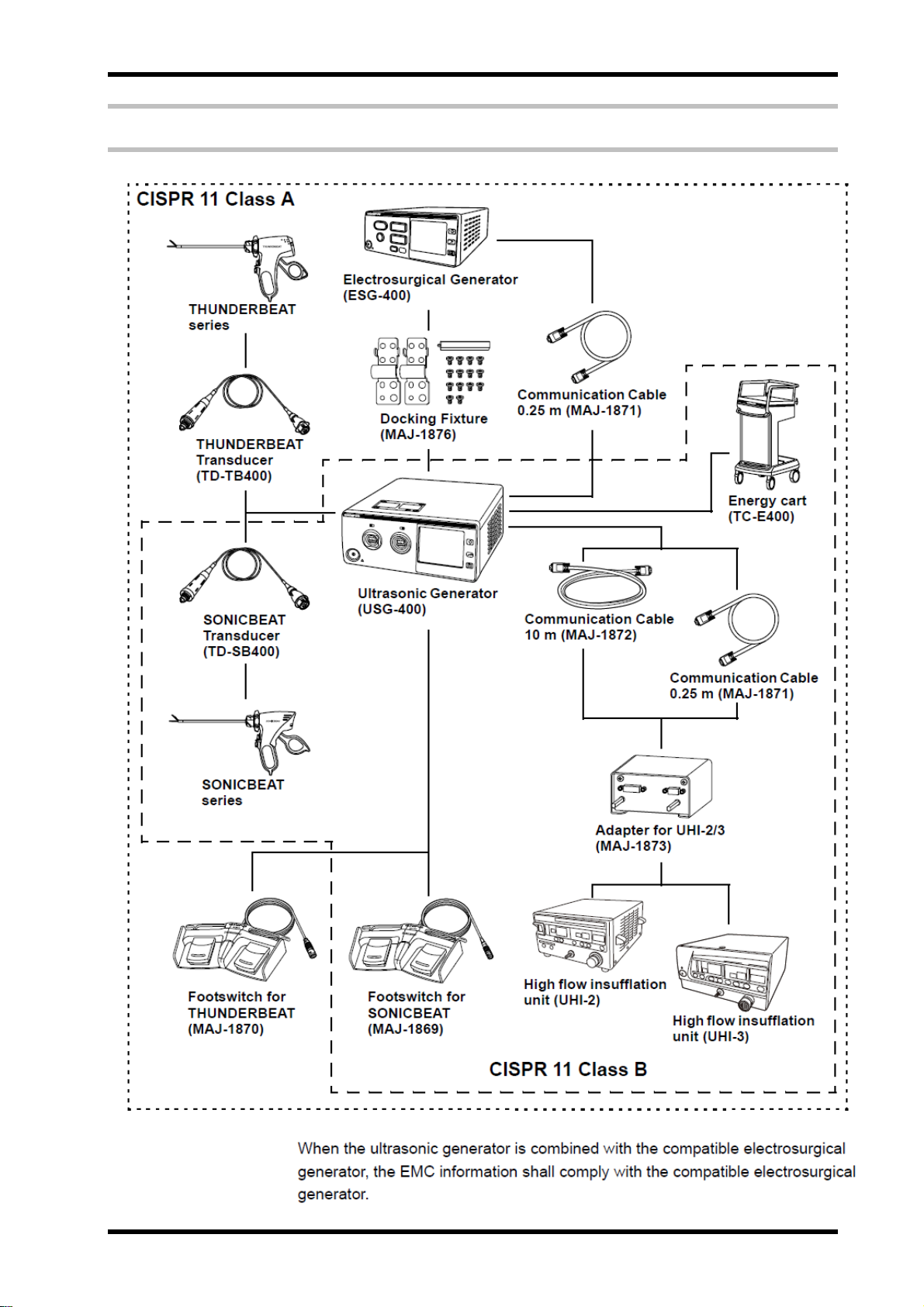
4 System chart
Product Outline 1-4 ISSUE1
Page 11

USG-400
Chapter 2 : Specifications
1 Specifications....................................................................................2-2
ISSUE1 2-1 Specifications
Page 12

USG-400
1 Specifications
○ Ultrasonic Generator USG-400
Power supply
Size
Rated voltage
Voltage fluctuation
Rated frequency
Frequency fluctuation
Rated input
Fuse rating
Fuse size
Dimensions
120 V AC (USA model)
220 - 240 V AC (EU model)
Within ±10%
50/60 Hz
Within ±1 Hz
360VA
4A,250VA
Φ5 X 20mm
375(w)X156(H)X480(D)mm
Weight
Classification
(medical
electrical
equipment)
Output
Medical
Devices
Directive
EMC Applied standard
Type of protection
against electric shock
Degree of protection
against electric
shock of applied part
Degree of protection
against explosion
The applicable
instrument
ON/OFF operation
Output setting
Frequency
Duty cycle
(Recommended cycle)
IEC 60601-1-2:2001
(2007)
9 kg
Class I
CF type
The ultrasonic generator should be kept away from
flammable gases.
THUNDERBEAT/SONICBEAT
Footswitch
Handswitch
Setting possible in the Set Screen displayed
on the touch panel.
47.0kHz
1 min. ON/1min. OFF
This device complies with the requirements of Diretive
93/42/EEC concerning medical devices.
Classification: Class Ⅱ b
This device complies with the EMC requirements of EN
60601-1-2:2007 when used in combination with devices
bearing CE marking either on the products or in its
instructions for use.
Emission: Class B of EN 55011
The ultrasonic generator complies with the standards
listed in the left column.
CISPR 11 of emission:
Group 1,Class B
The ultrasonic generator complies with the EMC standard
for medical electrical equipment; edition 3(IEC
60601-1-2:2007).However, when connecting to an
instrument that complies with the EMC standard for
medical electrical equipment, edition 1(IEC
60601-1-2:1993), the whole system complies with edition
1.
When the ultrasonic generator is combined with the
compatible electrosurgical generator, the EMC
information shall comply with the compatible
electrosurgical generator.
Specifications 2-2 ISSUE1
Page 13
USG-400
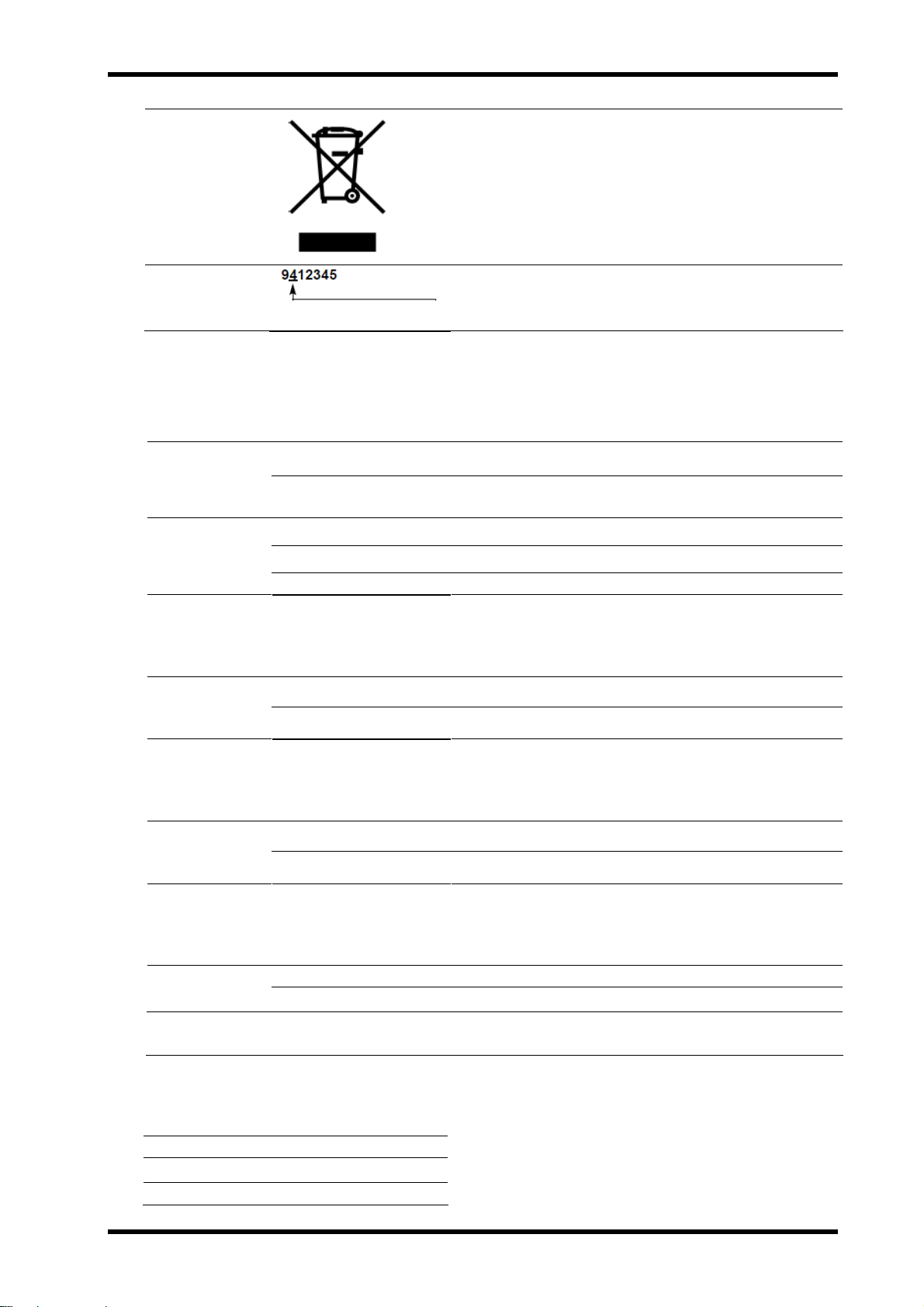
WEEE Directive
Year of
manufacture
In accordance with European Directive 2002/96/EC on
Waste Electrical and Electronic Equipment, this symbol
indicates that the product must not be disposed of as
unsorted municipal waste, but should be collected
separately.
Refer to your local Olympus distributor for return and/or
collection systems available in your country.
The last digit of the year of manufacture is given in the
second digit of the serial number.
○ Footswitch for THUNDERBEAT (MAJ-1870, optional)/
Footswitch for SONICBEAT (MAJ-1869, optional)
Classification
(medical
electrical
equipment)
Size
Degree of water
resistance
Degree of protection
against explosion
Dimensions
IEC60529 IPX8 water tight type
(except the plug section)
IEC6060101AP type
346(w)X64(H)X486(D)mm
Weight
Length of the cord
2.3 kg
4000 mm
○ Communication Cable 0.25m (MAJ-1871, optional)
Size
Weight
Length of the cord
0.04kg
250 mm
○ Communication Cable 10m (MAJ-1871, optional)
Size
Weight
Length of the cord
0.5kg
10,000 mm
○ Adapter for UHI-2/3 (MAJ-1873, optional)
Size
Applicable
Cables
Dimensions
Weight
94(w)X37(H)X71(D)mm
215 g
MAJ-1871, MAJ-1872
○ Docking Fixture (MAJ-1876, optional)
Screws
Hex wrench
Ficture plates
ISSUE1 2-3 Specifications
14 pcs
1 pc
2pcs
Page 14

Page 15

USG-400
Chapter 3 : Installation and Connection
1 Installation workflow.........................................................................3-2
2 Installation of the ultrasonic generator...........................................3-3
3 Connection of compatible electrosurgical generator
(when using the THUNDERBEAT) ....................................................3-4
4 Connection to power supply(Ultrasonic Generator) ....................3-11
5 Automatic mist & smoke evacuation system/function
(When using the compatible high flow insufflation unit).............3-12
6 Connection of footswitch (optional)..............................................3-15
7 Connection of the THUNDERBEAT and/or SONICBEAT
(various options available) .............................................................3-17
ISSUE1 3-1 Installation and Connection
Page 16
USG-400
Prepare the ultrasonic generator and ancillary equipment for the intended purpose by referring to “System chart”
in the Product Outline. Install and connect the ultrasonic generator and ancillary equipment as described in the
following sections and also by referring to the instruction manuals for the ancillary equipment.
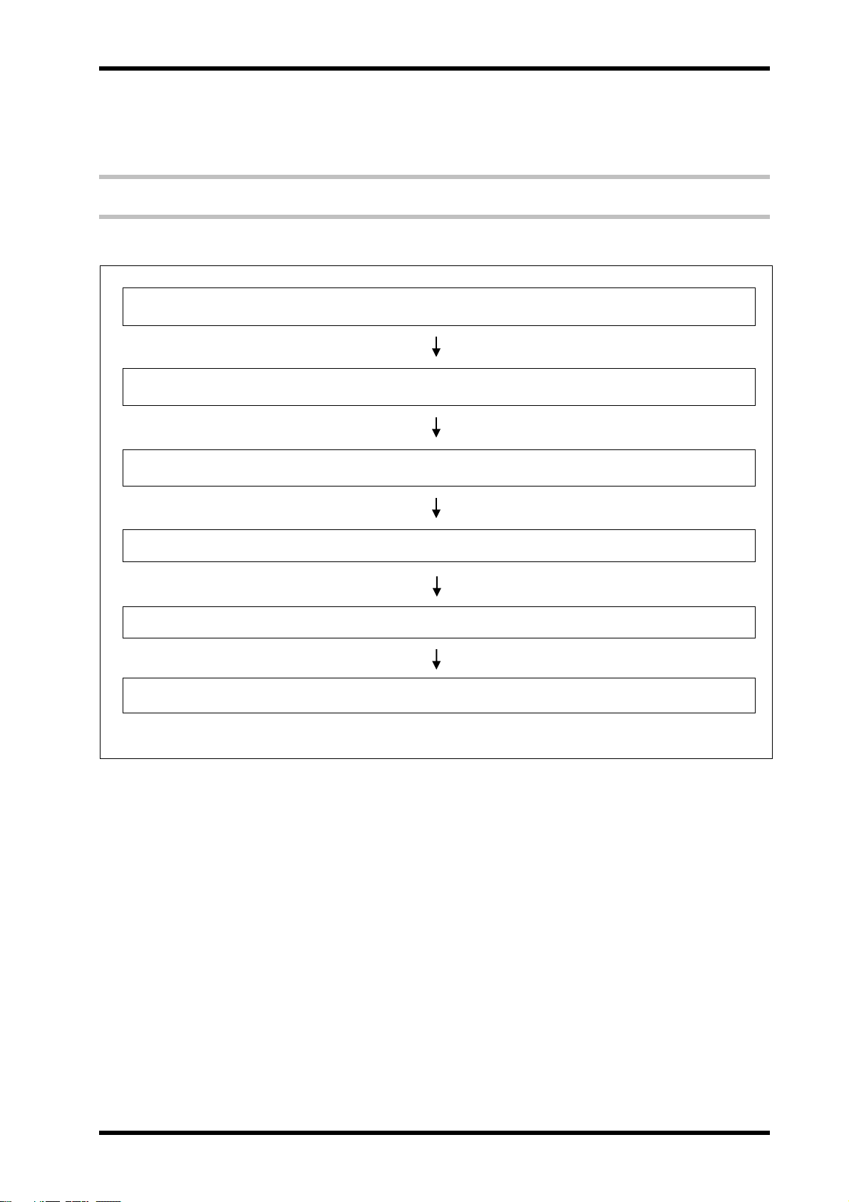
1 Installation workflow
The following is the equipment installation workflow. For detailson each step, read the corresponding description.
1. Section 2 “Installation of the ultrasonic generator”
2. Section 3 “Connection of compatible electrosurgical generator
(when using the THUNDERBEAT)”
3. Section 4 “Connection to power supply (Ultrasonic Generator)”
4. Section 5 “Automatic mist & smoke evacuation system/function
(when using the compatible high flow insufflation unit)”
5. Section 6 “Connection of the footswitch(es)”
6. Section 7 “Connection of the THUNDERBEAT and/or SONICBEAT”
Installation and Connection 3-2 ISSUE1
Page 17

USG-400
2 Installation of the ultrasonic generator
CAUTION
NOTE
1. Checking the operationg conditions
Confirm that the operating conditions comply with the information provided in
“Danger, warnings, and cautions.
2. Installing the trolley (cart)
When using the energy cart TC-E400, prepare the cart by following its instruction
manual.
3. Installing the ultrasonic generator
Place the ultrasonic generator on a stable trolley (cart) or a level, stable platform.
Use of the energy cart TC-E400 is highly recommended.
Heed the following cautions when installing the ultrasonic generator in
a position other than on the energy cart shown in the “System chart” in
the Product Outline.
− Install the ultrasonic generator on a level, stable platform.
If the ultrasonic generator slips from or topples down from an u
nstable installation position, the patient, surgeon and/or surgical
staff may be injured. Furthermore, equipment damage may
occur.
− Confirm that the installation position has enough strength and
size for supporting the ultrasonic generator. If it is not strong
enough, the ultrasonic generator may fall and be damaged.
Be careful when the trolley (cart) containing the ultrasonic
generator and other equipment are transported on a non-level
surface or across an obstacle cable. If the trolley (cart) is
transported over an obstacle, the ultrasonic generator and other
equipment may tip over possibly resulting in equipment failure.
Do not install the ultrasonic generator on its side or upside down.
Otherwise, a failure or malfunction may occur.
Do not install the ultrasonic generator in close contact with a
wall or other equipment in a manner that would block the
ventilation opening. Otherwise, the generator may overheat.
Be careful not to pinch a hand when installing the ultrasonic
generator.
Avoid applying excessive force on the socket connections.
Otherwise, wire disconnection or other failure may occur.
Always use the ultrasonic generator in compliance with the
“Operating environment” specified in the Product Outline.
Otherwise, the ultrasonic generator may fail.
Keep the instruction manual in an easily accessible place near
the ultrasonic generator.
Before connecting an accessory to the ultrasonic generator, read
And understand the instruction manual for the accessory
thoroughly and confirm the compatibility of the ultrasonic
generator.
ISSUE1 3-3 Installation and Connection
Page 18

USG-400
3 Connection of compatible electrosurgical
generator (when using the THUNDERBEAT)
WARNING
CAUTION
Never connect a cable other than the optional communication
cable to the ultrasonic generator. Otherwise, the ultrasonic
generator cannot perform appropriately and injury or equipment
damage may result.
Avoid applying excessive force on the communication cable.
Otherwise, wire disconnection or other failure may result.
Be sure to retain the docking plug cover. If it is lost, the
ultrasonic generator cannot be used in the standalone
configuration.
Be sure not to lose the tools such as screws and fixture
plates. If these items are lost, the ultrasonic generator cannot
be connected to the compatible electrosurgical generator.
Connect the docking connector and docking plug correctly.
Otherwise, malfunction or ultrasonic generator damage may result.
Avoid getting liquid inside the ultrasonic generator.
Otherwise, it may be damaged.
Avoid applying excessive force on the docking connector,
docking plug and fixture plates. Otherwise, they may be damaged.
Heed the following cautions when assembling the docking
connector and docking plug:
− Be careful not to pinch a finger.
− Be careful not to drop a screw in the area around the docking
plug.
Connect the docking plug to the docking connector properly.
Improper connection such as oblique insertion or contamination
may cause output irregularities.
Securely fix the fixture plates on the compatible electrosurgical
generator. Otherwise, the compatible electrosurgical generator may
fall.
Remove the fixture plate prior to lifting the compatible
electrosurgical generator. Otherwise, the fixture plates may be
damaged.
Do not remove screws other than those screws that are
instructed to do so in the manual.
Disconnect the docking connector and/or the docking plug
properly as described in “Disconnection” on page 3-10
Otherwise, the ultrasonic generator, docking connector and/or
docking plug may be damaged.
Before connecting the compatible electrosurgical generator,
be sure that the power cord of the ultrasonic generator is
unplugged from the AC power socket on the ultrasonic generator.
When removing the docking plug cover, be careful to maintain
pressure on the cover, because the docking plug is spring-loaded.
Installation and Connection 3-4 ISSUE1
Page 19
USG-400
The THUNDERBEAT performs cutting and coagulation using high frequency (RF
bipolar) and ultrasonic energy. When it is used, both the compatible
electrosurgical and ultrasonic generators are required.
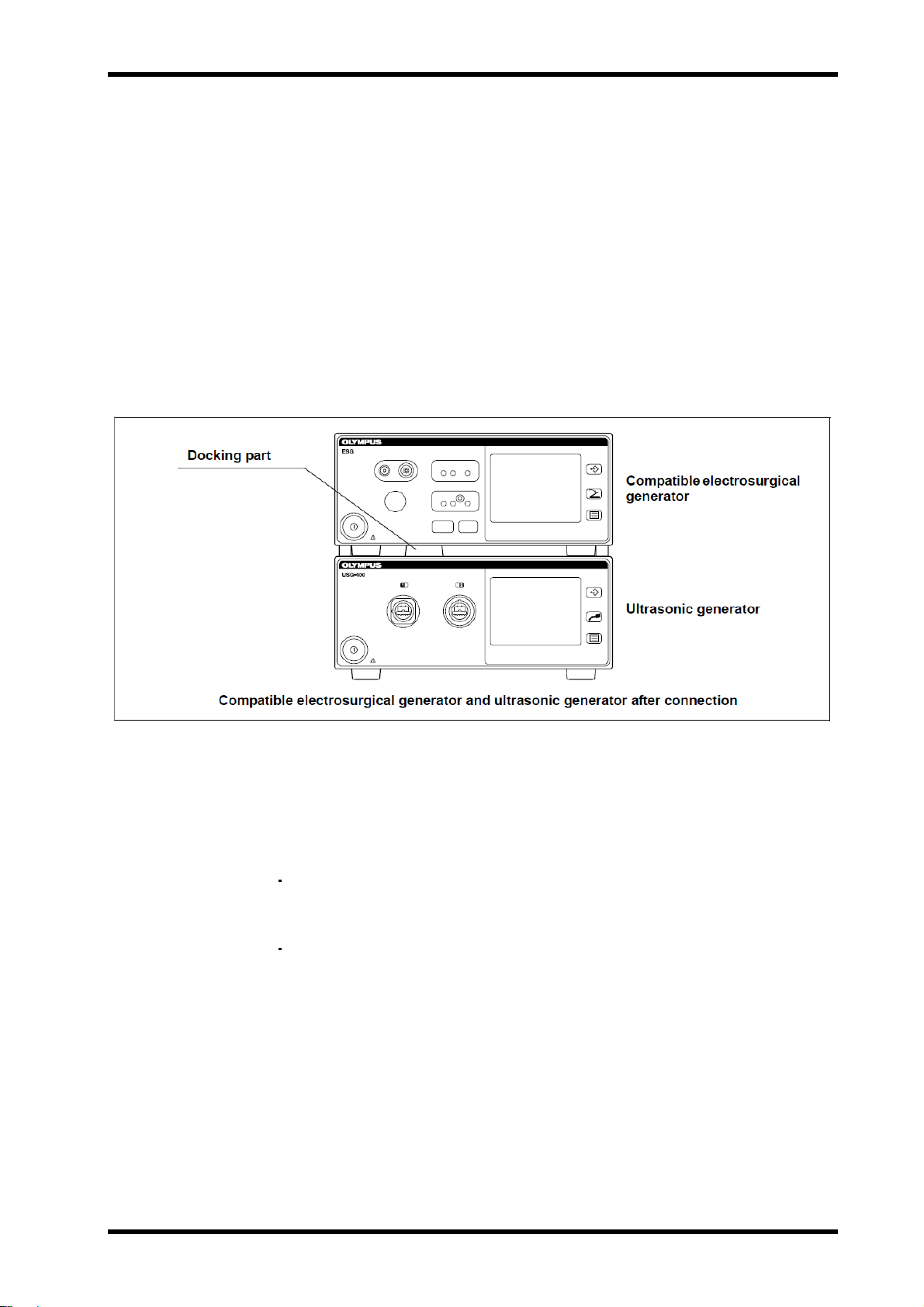
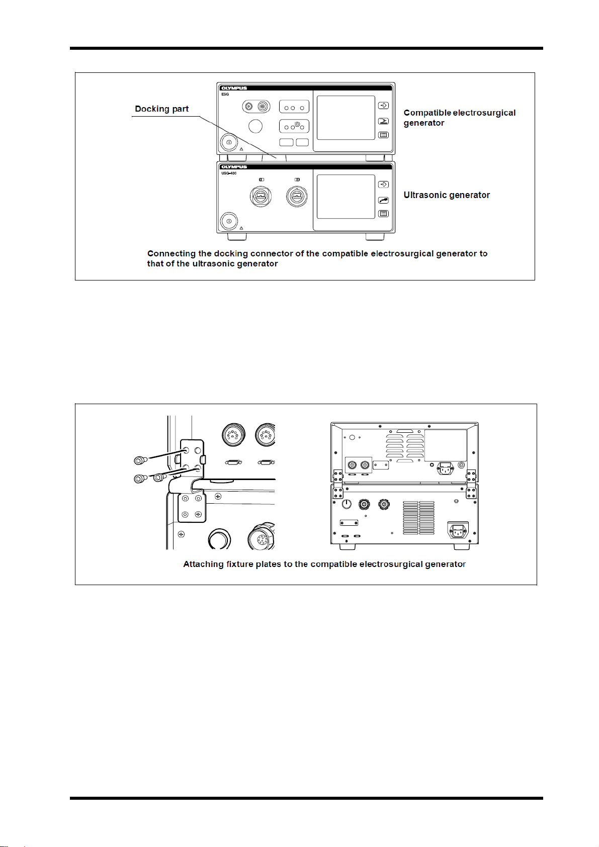
To transmit the high-frequency (RF bipolar) energy from the compatible
electrosurgical generator to the ultrasonic generator, a docking connector and
docking plug are provided on each of these generators.
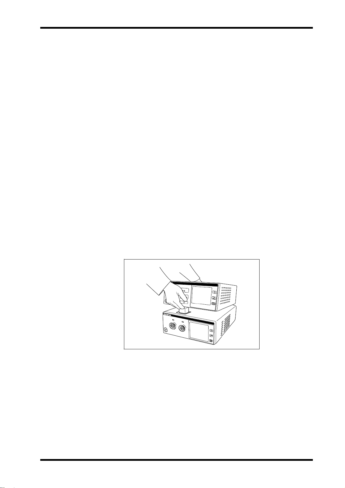
To connect the two generators, align the docking connector at the bottom of the
compatible electrosurgical generator into the docking plug at the top of the
ultrasonic generator.
After the alignment is made, the compatible electrosurgical generator is placed
on top of ultrasonic generator (see Figure 3.1).
This section describes how to connect and disconnect the docking connector
and docking plug.
Figure 3.1
Connection
1. Preparing the docking fixture
Prepare the docking fixture (MAJ-1876).
The docking fixture includes the tools for use in connection, including
2 fixture plates, 14 screws (12 pcs for the fixture plates and 2 pcs for the
docking plug cover) and a hex wrench.
All of the screws used in the connection between the compatible
electrosurgical generator and ultrasonic generator should be
tightened/loosened using the hex wrench.
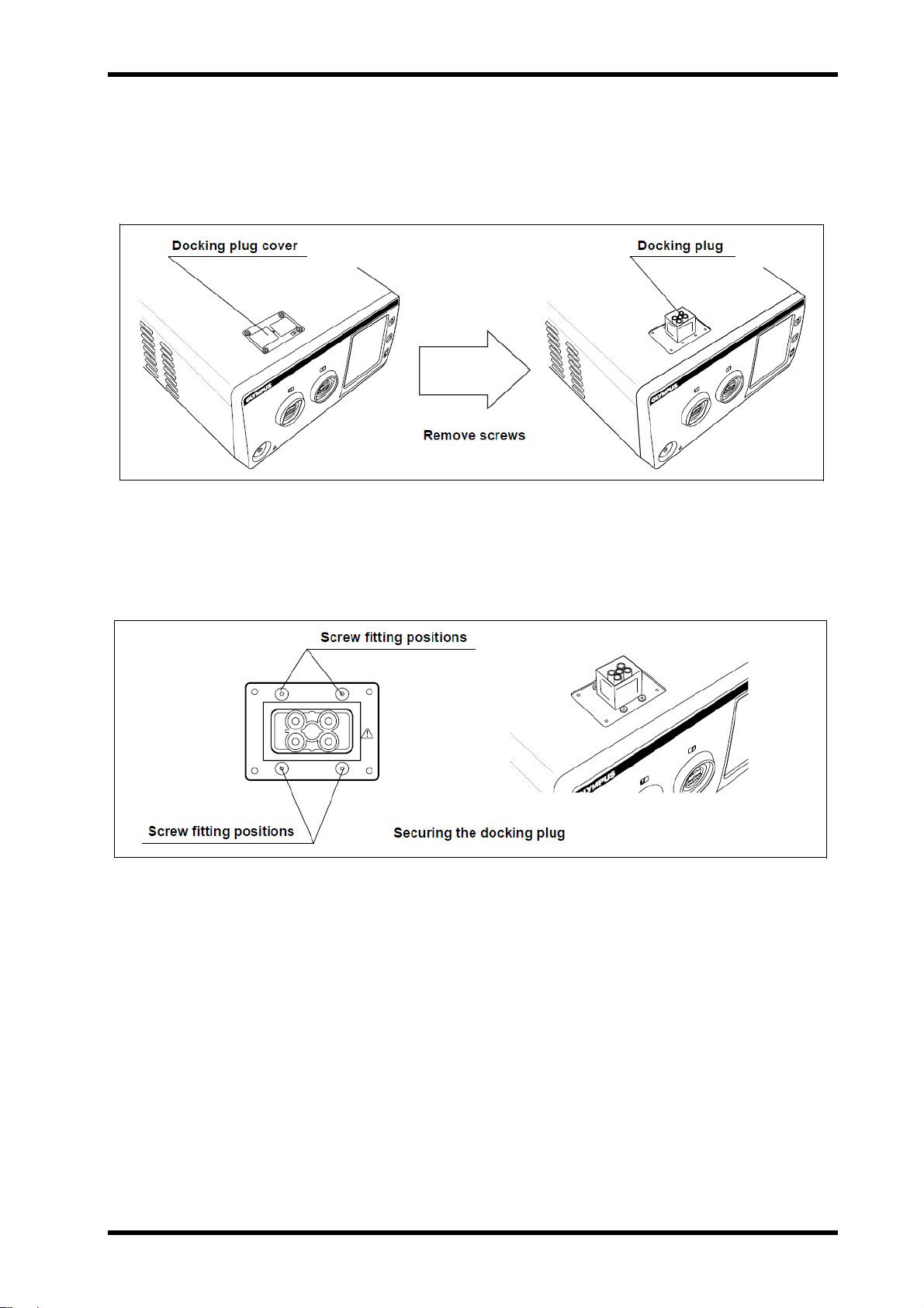
2. Checking the docking plug cover
Confirm the position of the docking plug cover, which is a rectangular plate
on the top panel (near front) of the ultrasonic generator (see Figure 3.2).
Behind the docking plug cover is the docking plug for connection of the
compatible electrosurgical generator.
ISSUE1 3-5 Installation and Connection
Page 20
USG-400
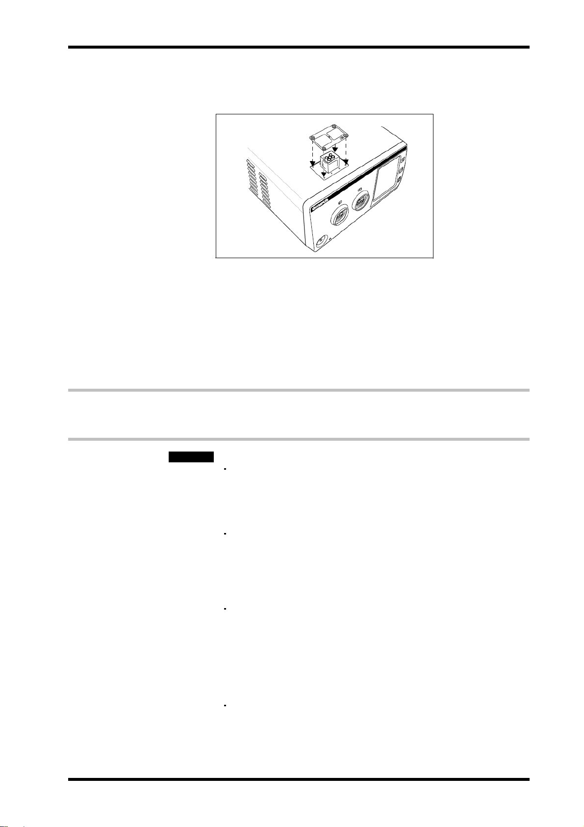
3. Removing the docking plug cover
Holding the docking plug cover, remove four screws from the docking plug
cover (see Figure 3.2). Retain the docking plug cover.
Removing the docking plug cover exposes the docking plug.
Figure 3.2
4. Securing the docking plug
Insert the screws removed in step 3 into the four positions around the
docking plug and tighten securely (see Figure 3.3).
Figure 3.3
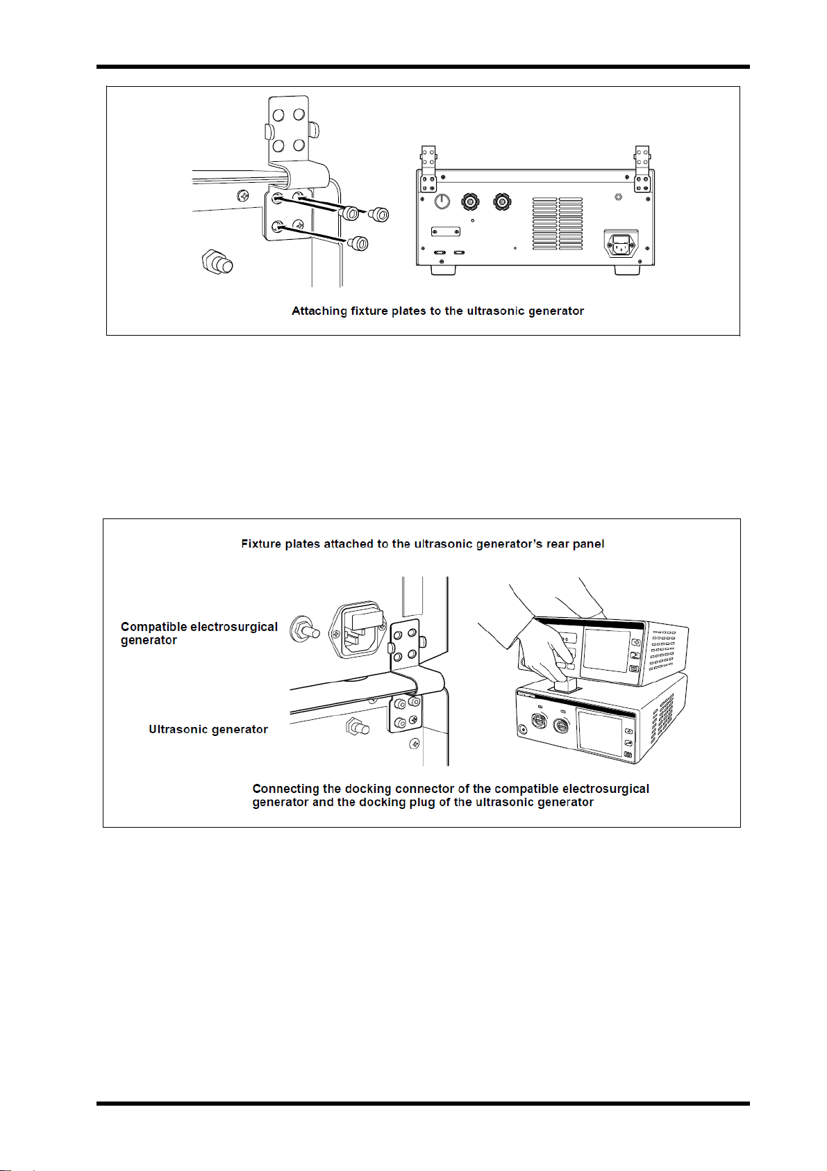
5. Attaching the fixture plates to the ultrasonic generator
Attach the fixture plates on two positions at the top left and top right of the
rear panel of the ultrasonic generator using three screws for each plate (see
Figure 3.4).
Installation and Connection 3-6 ISSUE1
Page 21
USG-400
Figure 3.4
6. Connectiong
Align the rear panel of the compatible electrosurgical generator with the
fixture plates and then lower the front edge of the compatible
electrosurgicalgenerator slowly (see Figures 3.5 and 3.6).
Align the compatible electrosurgical generator with the fixture plates
ensures alignment of the docking plug and docking connector.
Figure 3.5
ISSUE1 3-7 Installation and Connection
Page 22
USG-400
Figure 3.6
7. Attaching the fixture plates to the compatible electrosurgical generator
attach the fixture plates that have been attached to the rear panel of the
ultrasonic generator to the compatible electrosurgical generator using three
screws for each plate (see Figure 3.7).
The fixture plates ensure tight clamping of the two generators.
Figure 3.7
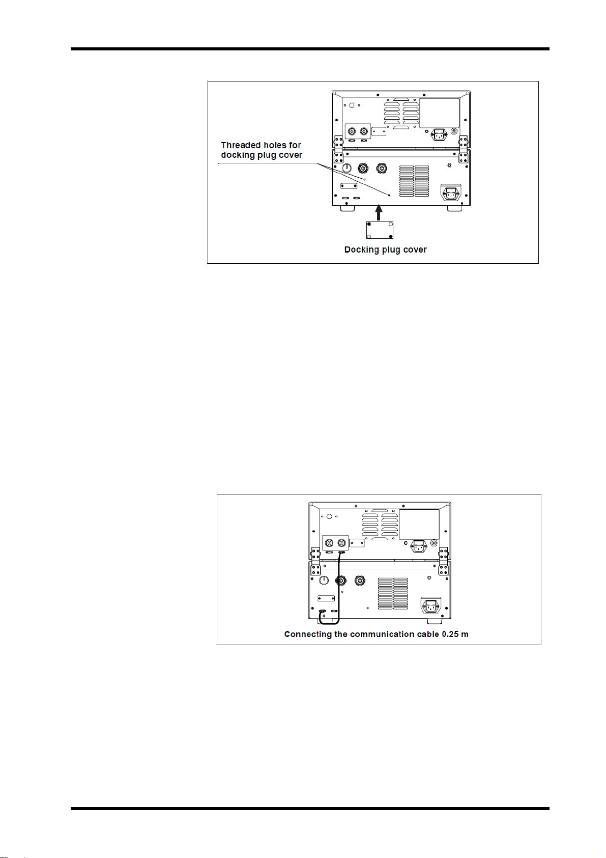
8. Storing the docking plug cover
Attach the docking plug cover, which has been removed in step 3 above, to
the threaded holes for the docking plug cover on the rear panel of the
ultrasonic generator using two screws (see Figure 3.8).
Installation and Connection 3-8 ISSUE1
Page 23
USG-400
Figure 3.8
9. Storing the tool
Store the hex wrench in a nearby location such as the drawer of the cart.
10. Connecting the communication cable 0.25m
Connect the LINK-IN and LINK-OUT plugs of the communication cable
0.25 m to the communication connectors on the rear panels of the ultrasonic
generator and compatible electrosurgical generator. After connection, secure
each plug by pushing it in while turning the screws on both sides of the plug
(see Figure 3.9).
Example: Connect the communication cable 0.25 m LINK-IN plug to the
LINK-IN connector on the rear panel of the ultrasonic generator
and connect the communication cable 0.25 m LINK-OUT plug
on the other end to the communication connector on the rear
panel of the compatible electrosurgical generator.
Figure 3.9
ISSUE1 3-9 Installation and Connection
Page 24
USG-400
Disconnection
1. Preparing the stored tool
Prepare the hex wrench that has been stored after the connection.
All screws used in this disconnection should be handled by the hex wrench.
2. Disconnecting the communication cable 0.25m
Loosen the plugs of the communication cable 0.25 m connected to the rear
panels of the ultrasonic generator and compatible electrosurgical generator
by loosening the screws on both sides of each plug by hand, and then
unplug the plugs.
3. Removing the docking plug cover
Remove the docking plug cover from the rear panel of the ultrasonic
generator.
4. Removing the fixture plates from the compatible electrosurgical generator
remove screws from the fixture plates attached to the rear panel of the
compatible electrosurgical generator.
5. Separating the generators
Hold the front side of the compatible electrosurgical generator and lift it (see
Figure 3.10).
6. Removing the docking plug screws.
Remove screws from the four positions around the docking plug.
7. Removing the fixture plates from the ultrasonic generator.
Remove screws from the fixture plates attached to the rear panel of the
ultrasonic generator.
Figure 3.10
Installation and Connection 3-10 ISSUE1
Page 25
8. Secureing the docking plug
Place the docking plug cover on the docking plug and push the cover slowly
with your hand to cover the docking plug (see Figure 3.11).
USG-400
Figure 3.11
9. Secureing the docking plug cover
Attach the screws that have been removed in step 7 on the four corners of
the docking plug cover.
10. Storing the parts and tools
Store the removed fixture plates X 2, screws X 14 and the hex wrench.
4 Connection to power supply
(Ultrasonic Generator)
WARNING
Connect the power cord firmly so that it is not unplugged
accidentally during operation, and avoid excessive bending,
straining or twisting. Otherwise, the power cord may become
unplugged or damaged. If damaged, an electric shock or fire
hazard may result.
The ultrasonic generator requires grounding for safety. To
avoid an electric shock, always connect the power cord plug
to a properly grounded hospital-grade 3-conductor power
outlet. Do not use an adapter that converts the 3-conductor
power plug into a 2-conductor plug because this may impair
the safety of the unit.
Confirm that the power capacity of the hospital-grade power
outlet to which the ultrasonic generator is connected is
sufficient for all the equipment connected to it including the
ultrasonic generator. If the power capacity of the power outlet
is insufficient, a fire hazard may result and the circuit breaker
of the hospital may trip, turning OFF all of the equipment
connected to the power supply including the ultrasonic
generator.
Do not use an extension cord and power strip in the power
supply line. Otherwise, improper installation/connection may
cause an electric shock hazard.
ISSUE1 3-11 Installation and Connection
Page 26
USG-400
CAUTION
Before connecting the power supply, make sure that it
conforms to the power specifications described on the rating
plate of the ultrasonic generator.
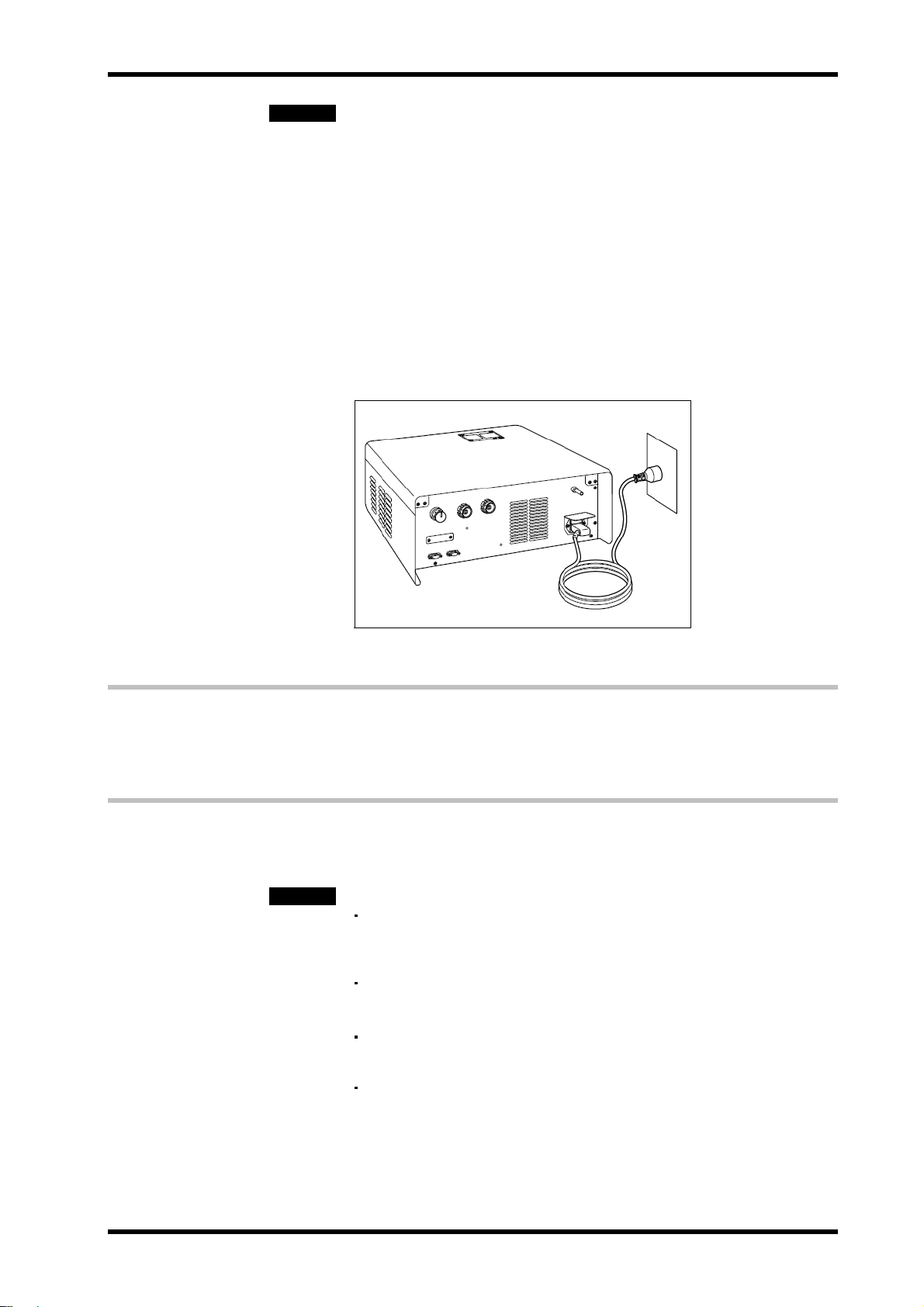
1. Connecting the power cord
Connect the power cord of the ultrasonic generator to the AC power socket
on the rear panel of the ultrasonic generator (see Figure 3.12).
2. Connecting to the power outlet
Connect the power cord directly to a hospital-grade 3-conductor power
outlet that meets the electrical rating inscribed on the rating plate of the
ultrasonic generator (see Figure 3.12).
Figure 3.12
5 Automatic mist & smoke evacuation
system/function (When using the compatible
high flow insufflation unit)
When the THUNDERBEAT or SONICBEAT is activated, automatic mist & smoke evacuation system/function of
UHI-2/3 work with activation simultaneously to evacuate the smoke and mist produced in the abdominal cavity.
CAUTION
When using the automatic mist & smoke evacuation
system/function, also refer to the instruction manual for the
compatible high flow insufflation unit.
Avoid applying excessive force to the communication cable.
Otherwise, wire disconnection or other failure may result.
The 2-way cable for aeration and extension cable for aeration
are not allowed to use for the ultrasonic generator.
When using the ultrasonic generator with the compatible
electrosurgical generator and the compatible high flow
insufflation unit simultaneously, contact Olympus.
Installation and Connection 3-12 ISSUE1
Page 27
USG-400
1. Preparation
Prepare the adapter for UHI-2/3 and the communication cable 10 m.
The compatible high flow insufflation unit cannot be connected directly
to the ultrasonic generator. The use of an adapter for UHI-2/3 is required
for the connection.
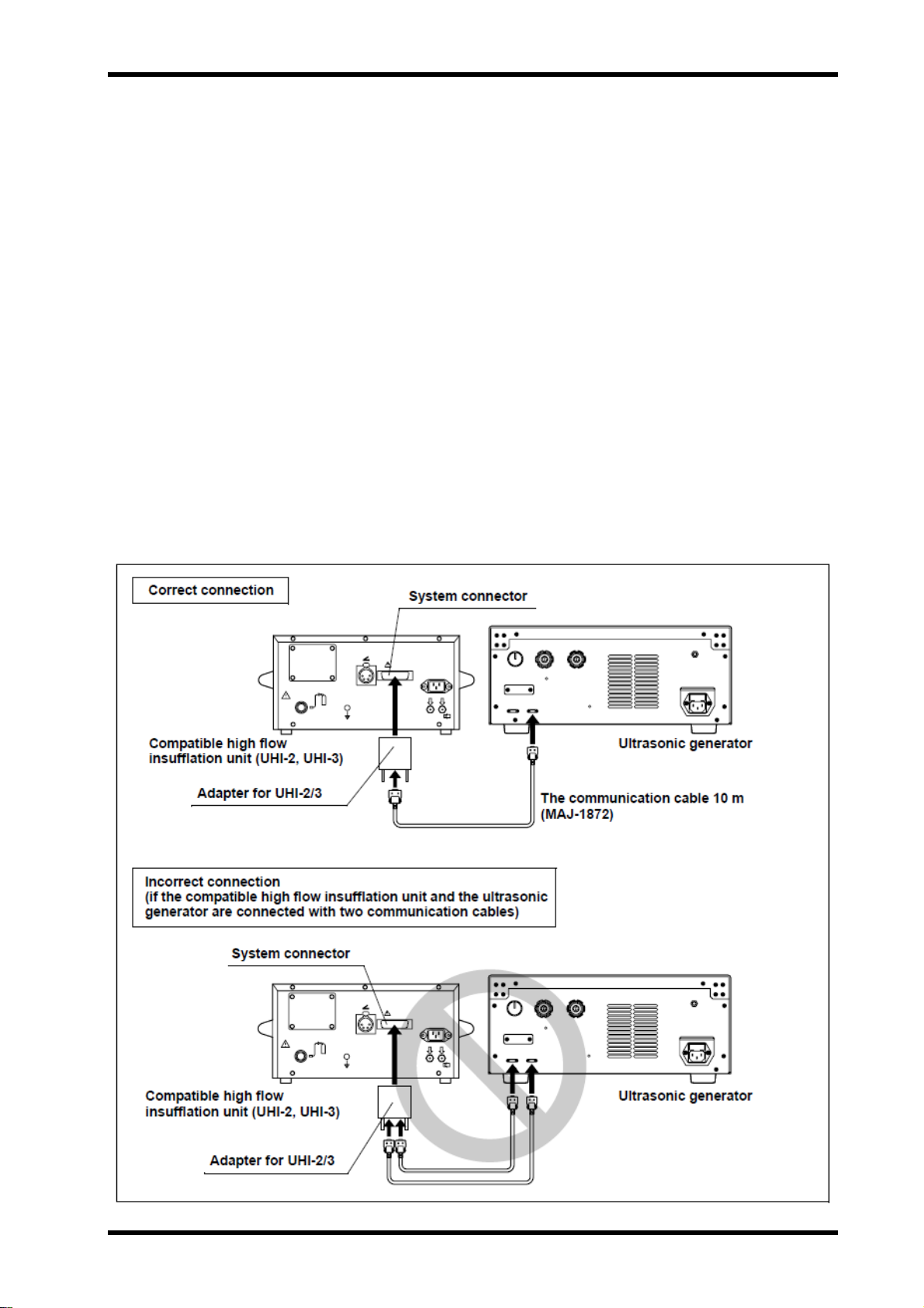
2. Connecting the adapter for UHI-2/3
Connect the system plug of the adapter for UHI-2/3 to the system connector
on the rear panel of the compatible high flow insufflation unit. After
connection, secure the system plug by fasten the screws on both sides of
the plug (see Figure 3.13).
3. Connecting the communication cable 10m to the adapter for UHI-2/3
Connect the plug of the communication cable 10 m to the LINK-IN or
LINK-OUT connector of the adapter for UHI-2/3. After connection, secure
each plug by pushing it in while turning the screws on both sides of the plug
(see Figure 3.13).
4. Connecting the communication cable 10m (to the ultrasonic generator)
Connect the other plug of the communication cable 10 m that has been
connected to the adapter for UHI-2/3 to the LINK-IN or LINK-OUT connector
of the ultrasonic generator. After connection, secure each plug by pushing it
in while turning the screws on both sides of the plug (see Figure 3.13).
Figure 3.13
ISSUE1 3-13 Installation and Connection
Page 28
USG-400
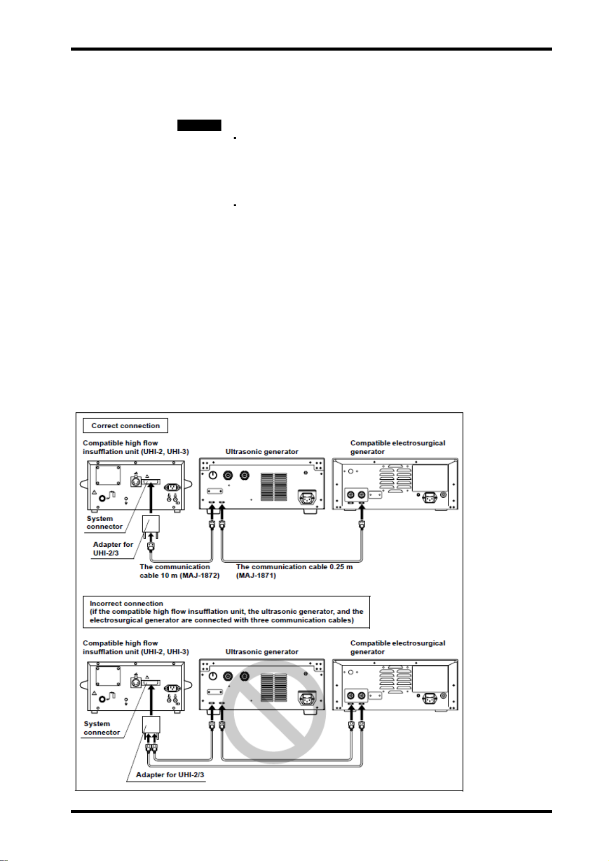
When adding the compatible electrosurgical generator to the compatible high
flow insufflation unit and the ltrasonic generator.
CAUTION
When adding the compatible electrosurgical generator to the compatible high flow insufflation unit and the
ultrasonic generator that have been already connected, follow the below steps (see Figure 3.14).
To prevent malfunction, connect either the compatible
electrosurgical or ultrasonic generator to the compatible high
flow insufflator. Do not connect both the compatible
electrosurgical and ultrasonic generators to the insufflator at
the same time.
When connecting three devices or more, do not use two of
communication cable 10 m. Otherwise, the communication
may fail.
1. Connecting the communication cable 0.25 m to the compatible
electrosurgical generator
Connect the plug of the communication cable 0.25 m to the LINK-IN or
LINK-OUT connector of the compatible electrosurgical generator.
2. Connecting the communication cable 0.25 m to the ultrasonic generator
Connect the other plug of the communication cable 0.25 m to the LINK-IN or
LINK-OUT connector of the ultrasonic generator.
Figure 3.14
Installation and Connection 3-14 ISSUE1
Page 29

6 Connection of footswitch (optional)
There are two kinds of footswitches, the THUNDERBEAT and SONICBEAT footswitches. This section
describes how to connect these footswitches.
WARNING
CAUTION
Connection of the footswitch for THUNDERBEAT
1. Checking the footswitch
Confirm that the footswitch cable and footswitch plug are free of damage
and that the pedals are free of cracks or separation (see Figure 3.15).
Do not connect any equipment other than the optional
footswitch to the footswitch socket. Otherwise, the system
cannot perform appropriately and injury and/or equipment
damage may also result.
Do not place a heavy object, such as a trolley (cart), on the
footswitch cable. Otherwise, cable disconnection may result.
Do not drop to the footswitch.
Always hold the footswitch plug section when connecting or
disconnecting it. Otherwise, the cable may separate from the
footswitch plug.
Avoid applying excessive force to the cable and the end of
the footswitch plug when connecting the footswitch plug.
Otherwise, the cable may separate from the plug or other
failure may result. If it is expected that the cable may be
subject to excessive force, move the ultrasonic generator
and footswitch to appropriate positions.
USG-400
Figure 3.15
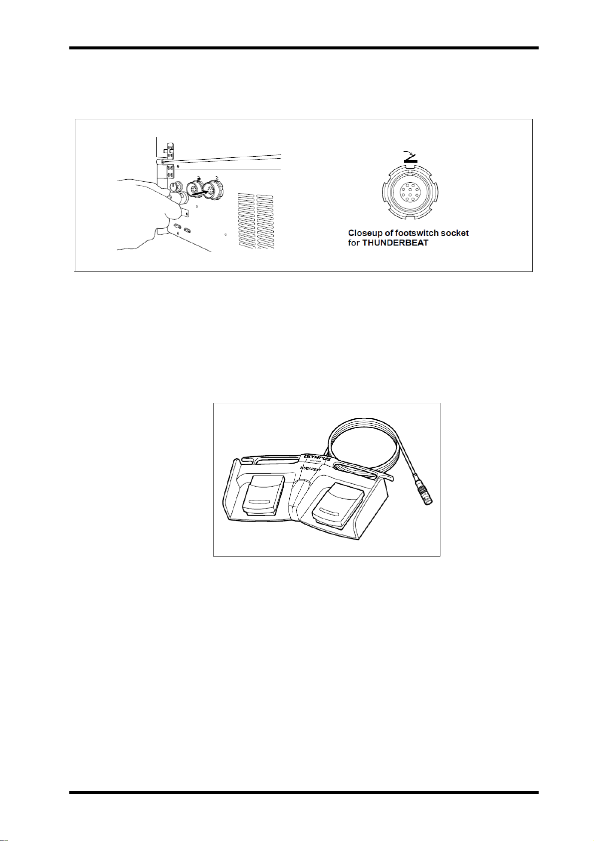
2. Checking the footswitch pedal operation
Press each pedal and confirm that it functions smoothly.
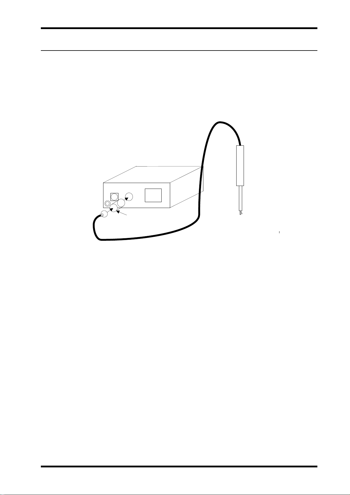
3. Checking the position of the footswitch plug and footswitch socket
Align the index (red circle) on the footswitch plug with the index (red circle)
on the THUNDERBEAT footswitch socket (silver) on the rear panel of the
ultrasonic generator (see Figure 3.16).
ISSUE1 3-15 Installation and Connection
Page 30
USG-400
4. Connecting the footswitch plug
Insert the footswitch plug all the way into the footswitch socket (as indicated
by the arrow in Figure 3.16).
Figure 3.16
Connection of the footswitch for SONICBEAT
1. Checking the footswitch
Confirm that the footswitch cable and footswitch plug are free of damage
and that the pedals are free of cracks or disengagement (see Figure 3.17).
Figure 3.17
2. Checking the footswitch pedal operation
Press each pedal and confirm that it functions smoothly.
3. Checking the position of the footswitch plug and footswitch socket
Align the index (red circle) on the footswitch plug with the index (red circle)
on the SONICBEAT footswitch socket (black) on the rear panel of the
ultrasonic generator (see Figure 3.18).
4. Connecting the footswitch plug
Insert the footswitch plug all the way into the footswitch socket (as indicated
by the arrow in Figure 3.18).
Installation and Connection 3-16 ISSUE1
Page 31

USG-400
Figure 3.18
Disconnecting footswitch plug
Holding the ultrasonic generator with one hand and the footswitch plug section with the thumb and index
finger on the other hand, pull out the plug (see Figure 3.19).
Hold the section indicated by the arrow when unplugging the footswitch
plug. The plug cannot be unplugged by pulling the section close to the
footswitch cable.
Figure 3.19
7 Connection of the THUNDERBEAT and/or
SONICBEAT (various options available)
The ultrasonic generator allows you to connect THUNDERBEAT and SONICBEAT to the transducer sockets.
Use either THUNDERBEAT or SONICBEAT according to the procedure to be performed and the desired tissue
effect.
Connect the transducer to the THUNDERBEAT or SONICBEAT instrument before connecting it to the
ultrasonic generator. For the connection of the THUNDERBEAT or SONICBEAT instrument to the transducer,
refer to the instruction manual for the THUNDERBEAT or SONICBEAT to be used.
ISSUE1 3-17 Installation and Connection
Page 32

USG-400
WARNING
CAUTION
Do not connect an instrument other than the
THUNDERBEAT or SONICBEAT to the transducer socket.
Otherwise, the system will malfunction and injury and/or
equipment damage may also result.
Do not touch the transducer plug contacts. Static electricity
that was accumulated during autoclaving may cause an
electric shock.
Always hold the transducer plug when connecting or
disconnecting the transducer plug to/from the ultrasonic
generator. Otherwise, excessive bending, straining, twisting
or crushing force may disconnect the cable.
Be sure to fully insert the transducer plug securely.
Otherwise, the unsecure connection may result in
unexpected disconnection of the transducer plug, resulting in
no output which could lead to potential bleeding.
Connecting the THUNDERBEAT to the ultrasonic generator
1. Checking the position and symbol 1
Confirm that the symbol 1 for THUNDERBEAT on the transducer plug and
transducer socket are identical (see Figure 3.20).
Figure 3.20
2. Connecting the transducer plug
Fully insert the transducer plug into the transducer socket of the ultrasonic
generator until it is fully seated.
Connecting the SONICBEAT to the ultrasonic generator
1. Checking the position and symbol 2
Confirm that the symbol 2 for SONICBEAT on the transducer plug and
transducer socket are identical (see Figure 3.21).
Installation and Connection 3-18 ISSUE1
Page 33

USG-400
Figure 3.21
2. Connecting the transducer plug
Fully insert the transducer plug into the transducer socket of the ultrasonic
generator until it is seated.
Disconnecting the THUNDERBEAT and SONICBEAT
Hold the ultrasonic generator with one hand and the transducer plug in the other
hand, pull out the transducer plug.
ISSUE1 3-19 Installation and Connection
Page 34

Page 35

USG-400
Chapter 4 : Care, Storage, and Disposal
1 Care....................................................................................................4-2
2 Storage...............................................................................................4-3
3 Disposal.............................................................................................4-3
ISSUE1 4-1 Care, Storage, and Disposal
Page 36

USG-400
1 Care
WARNING
CAUTION
After using the ultrasonic generator, immediately clean it using the following steps. If cleaning is delayed, the
organic dirt may solidify and become difficult to remove. Clean the ultrasonic generator periodically.
1. Turning the ultrasonic generator OFF
When using the THUNDERBEAT, turn the ultrasonic generator OFF first,
then turn OFF the compatible electrosurgical generator.
The switch is no longer illuminated.
The touch panel is no longer illuminated.
The push button is no longer illuminated.
2. Removing the THUNDERBEAT and/or SONICBEAT and communication
cables
Disconnect the THUNDERBEAT and/or SONICBEAT and communication
cables from this ultrasonic generator.
3. Unplugging the power cord
Unplug the power cord from the hospital-grade power outlet.
4. Cleaning
Remove dirt, dust and stains from the ultrasonic generator and disinfect its
surface using gauze moistened with disinfecting alcohol.
If blood and/or bodily fluids contaminate the ultrasonic generator,
remove them using gauze moistened with a neutral detergent solution.
After wiping the ultrasonic generator with liquid-moistened
gauze, allow it to dry completely before use. Otherwise, an
electric shock hazard may result.
Be sure to wear appropriate personal protective equipment
during maintenance. Otherwise, any patient blood and/or
body fluids that may have contaminated the ultrasonic
generator may cause infection. Personal protective
equipment includes goggles, facemask, waterproof gear and
chemical-resistant waterproof gloves.
Do not spray a chemical such as disinfecting alcohol directly
on the ultrasonic generator. Otherwise, the chemical
penetrating it through the ventilation openings may cause a
failure or malfunction.
Do not clean the THUNDERBEAT/SONICBEAT sockets,
other sockets and the AC power socket. Otherwise,
deformation or corrosion of the contacts may cause contact
failure as well as a malfunction of the ultrasonic generator
and accessories.
Do not soak the ultrasonic generator in water or sterilize it
with autoclaving or gas. Otherwise, a malfunction of the
ultrasonic generator may result.
Do not wipe the exterior with an abrasive cloth, etc.
Otherwise, the exterior surface will be scratched.
Care, Storage, and Disposal 4-2 ISSUE1
Page 37

USG-400
5. Drying
After wiping with disinfecting alcohol, be sure to dry the ultrasonic generator
completely prior to use.
2 Storage
CAUTION
1. Store location
Place the ultrasonic generator in a level posture on a stable surface. When it
is not placed on the energy cart.
2. Storge environment
Store the ultrasonic generator properly in a clean, dustless place in
compliance with the environmental conditions given in “Specifications” in the
Specifications.
Do not store the ultrasonic generator in a place that is
exposed to direct sunlight, X-rays, radioactivity or strong
electromagnetic waves (e.g., the vicinity of a microwave
therapeutic device, short-wave therapeutic device, MRI,
wireless set, cellular phone, etc.). Also avoid storing in places
of high temperatures, high humidity and where
moisture/water is present. Otherwise, the instrument may be
damaged and/or could present an infection control risk.
Do not apply excessive force to the transducer cord by
bending, straining or twisting it too much. Otherwise, the
damaged cord may cause malfunction.
Do not subject the ultrasonic generator to strong impacts
during storage. Doing so will damage the ultrasonic
generator.
3 Disposal
When disposing of the ultrasonic generator, be sure to observe your national and local laws and guidelines.
ISSUE1 4-3 Care, Storage, and Disposal
Page 38

Page 39

USG-400
Chapter 5 : Inspection
1 Verification workflow ........................................................................5-2
2 Power verification .............................................................................5-3
3 Verification of communication cable connection between
compatible electrosurgical generator and ultrasonic generator
(when using the THUNDERBEAT) ....................................................5-6
4 Verification of touch-screen and push buttons..............................5-7
5 Verification of the THUNDERBEAT and/ or SONICBEAT..............5-10
6 Verification of footswitch connection............................................5-13
7 Verification of the high-frequency(RF bipolar) output
(when using the THUNDERBEAT) ..................................................5-13
8 Verification of the alarm system....................................................5-17
9 Procedure after verification ..........................................................5-19
10 Inspection check sheet...................................................................5-20
ISSUE1 5-1 Inspection
Page 40

USG-400
WARNING
Prepare the ultrasonic generator and ancillary equipment for the surgical procedure by referring to “System
chart” in Product Outline. Inspect the ultrasonic generator and ancillary equipment by referring to the respective
instruction manuals.
Always inspect the ultrasonic generator as described in this
chapter before using. Also, inspect the ancillary equipment
used in combination with the ultrasonic generator according
to the instruction manuals. Should any irregularity be
observed, do not use the ultrasonic generator and take
proper measures by referring to Chapter 8
“Troubleshooting”. If the irregularity is still not resolved, do
not use the ultrasonic generator and contact Olympus. Using
irregular equipment may cause a malfunction and may also
result in an electric shock, burns and/or fire hazard.
1 Verification workflow
The following is the equipment inspection workflow. For details on each step, read the corresponding
description.
1. Section 2 “Power verification”
2. Section 3 “Verification of communication cable connection between compatible
electrosurgical generator and ultrasonic generator (when using the THUNDERBEAT)”
3. Section 4 “Verification of touch-screen and push buttons”
4. Section 5 “Vertification of the THUNDERBEAT and/or SONICBEAT connection(s)”
5. Section 6 “Vertification of footswitch connection”
6. Section 7 “Vertification of the high-frequency(RF bipolar) output
(when using the THUNDERBEAT)”
7. Section 8 “Vertification of the alarm system”
8. Section 9 “Procedure after verification”
Inspection 5-2 ISSUE1
Page 41

2 Power verification
WARNING
CAUTION
Checking the illumination of power switch, touch-screen, and push buttons
Depress the power switch of the ultrasonic generator (see Figure 5.1).
The periphery of the switch lights green.
The touch-screen is illuminated.
The push buttons is illuminated.
Confirm that the power switch, touch-screen and push
buttons illuminate when the ultrasonic generator is turned
ON. If not, check that the power cord is connected properly. If
they still do not illuminate and turn the power switch to OFF,
unplug the power cord and contact Olympus. Continuing the
use of the ultrasonic generator in this condition may result in
a fire or electric shock hazard.
Confirm that the start tone sounds when the ultrasonic
generator is turned ON. If the procedure is started without
confirming the start tone, unexpected burns, bleeding or
perforation may result. If the start tone does not sound,
contact Olympus.
When using THUDNERBEAT, turn the compatible
electrosurgical generator ON before the ultrasonic generator.
Otherwise, an error tone will be generated.
USG-400
Figure 5.1
Checking the start screen and start tone
Confirm that the “start screen” is displayed for 3 seconds on the touch-screen (see Figure 5.2).
Confirm that the start tone sounds at the same time that the “start screen” is displayed.
ISSUE1 5-3 Inspection
Page 42

USG-400
Figure 5.2
Checking the touch-screen display
Confirm that the “Set screen” or “All screen” is displayed after “start screen”
The displayed screen varies depending on whether one or two
THUNDERBEAT and SONICBEAT are connected (see Table 5.1).
When either THUNDERBEAT or SONICBEAT is connected, the
touch-screen displays the “Set screen” for the connected
THUNDERBEAT or SONICBEAT (see Figure 5.3).
When the two THUNDERBEAT and SONICBEAT are connected, the
touch-screen displays the “All screen”, in which the “THUNDERBEAT
button” and “SONICBEAT button” are shown (see Figure 5.4).
Either THUNDERBEAT or
SONICBEAT connected
Displayed
screen
Table 5.1 Relationship between THUNDERNBEAT and/or SONICBEAT
and screen display
Set screen for the connected
THUNDERBEAT or SONICBEAT
THHUNDER and SONICBEAT
connected
All screen in which the
THUNDERBEAT and SONICBEAT
buttons are shown
Inspection 5-4 ISSUE1
Page 43

USG-400
Figure 5.3
Figure 5.4
ISSUE1 5-5 Inspection
Page 44

USG-400
3 Verification of communication cable connection
between compatible electrosurgical generator
and ultrasonic generator
(when using the THUNDERBEAT)
When the communication indicator is illuminated
The lighting indicates that the communication status is normal (see Figure 5.5)
Figure 5.5
If the communication indicator is not illuminated
The communication cable 0.25 m between the compatible electrosurgical
generator and ultrasonic generator is not connected properly.
1. Confirm that the communication cable 0.25 m is connected properly to the generators.
2. Confirm that the power switches of the compatible electrosurgical and
ultrasonic generators are set to ON. If the power switches are not ON turn
the compatible electrosurgical generator ON first, then turn ON the ultrasonic generator.
If the communication indicator is not illuminated even after the above
check, contact Olympus.
Inspection 5-6 ISSUE1
Page 45

USG-400
4 Verification of touch-screen and push buttons
The touch-screen displays generator control buttons.
CAUTION
Checking the touch-screen operation
1. When either THUNDERBEAT or SONICBEAT is connected
Displayed screen: Set screen.
Press the “Plus or Minus button” (see Figure 5.6).
Pressing the “Plus button” increases the output level.
Pressing the “Minus button” decreases the output level.
Pressing and holding the “Plus or Minus button” varies the output level continuously.
2. Press the “Return button” on the bottom right of the screen (see Figure 5.6).
The screen changes from the “Set screen” to the “All screen”.
To prevent malfunction, do not press more than one part on
the touch-screen simultaneously.
Do not touch the touch-screen from the oblique direction.
Otherwise, the touch-screen may cause an incorrect
adjustment.
Unintended contact with the touch-screen may cause
unintended setting changes. Before activating energy output
confirm that the current setting is correct.
To prevent malfunction or damage to the touch-screen, do
not press the surface excessively.
Do not control the touch-screen with a pointed object (such
as tweezers or pen). Otherwise, damage may result.
Dirt and dust between the touch-screen and front panel may
cause malfunction of the touch-screen. To prevent this, keep
the touch-screen clean.
After pressing the “Plus or Minus button”, confirm that the
output level is changed accordingly. Otherwise, unintended
output may result.
ISSUE1 5-7 Inspection
Page 46

USG-400
Figure 5.6
When THUNDERBEAT and SONICBEAT are connected
Display screen: All screen
1. Press the “THUNDERBEAT or SONICBEAT button” on the screen (see Figure 5.7)
The screen changes from the “All screen” to the “Set screen”
2. Press the “Plus or Minus button” (see Figure 5.7).
Pressing the “Plus button” increases the output level.
Pressing the “Minus button” decreases the output level.
Pressing and holding the “Plus or Minus button” varies the output level continuously.
3. Press the “Return button” on the bottom right of the screen (see Figure 5.7).
The screen changes from the “Set screen” to the “All screen”.
Inspection 5-8 ISSUE1
Page 47

USG-400
Figure 5.7
Checking the push button operations
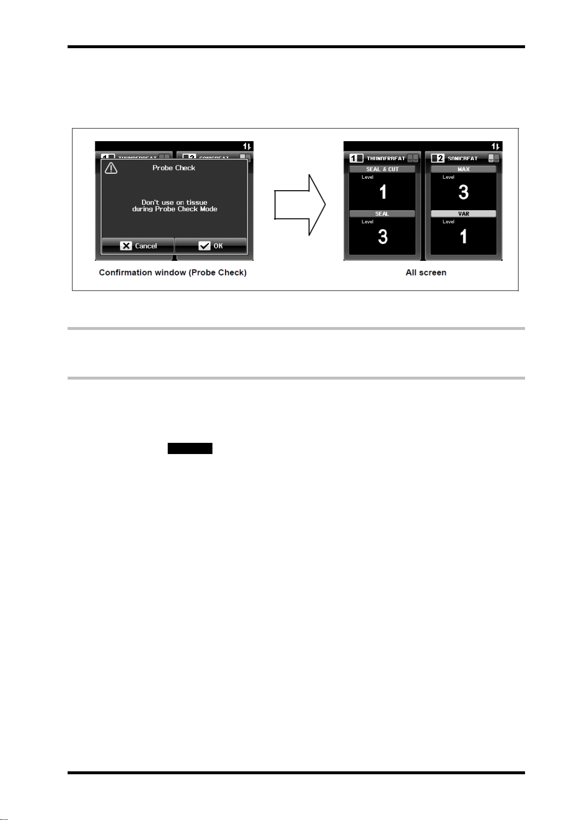
1. Press the “PROBE CHECK push button” (see Figure 5.8).
The “All screen” displays the confirmation window (Probe Check).
Figure 5.8
ISSUE1 5-9 Inspection
Page 48
USG-400
2. Press the “Cancel button” on the bottom left of the screen (see Figure 5.9).
The confirmation window (probe check) disappears and the “All screen”
is displayed again.
Figure 5.9
5 Verification of the THUNDERBEAT
and/ or SONICBEAT
The connection status of the THUNDERBRAT or SONICBEAT can be checked by the touch-screen display
after the ultrasonic generator is turned ON. Note that, however, the displayed screen differs depending on
whether one single THUNDERBEAT or SONICBEAT is connected or both THUNDERBEAT and SONICBEAT
instruments are connected.
WARNING
Verify the symbol for the connected THUNDERBEAT and / or SONICBEAT
When either THUNDERBEAT or SONICBEAT is connected
Displayed screen: Set screen
After turning the ultrasonic generator ON, confirm that the “Set screen” for the
appropriate connected THUNDERBEAT or SONICBEAT is displayed.
The symbols on the connected THUNDERBEAT or SONICBEAT and
displayed on the touch-screen must be identical.
The displayed name of the THUNDERBEAT or SONICBEAT on the
touch-screen must match the type of the THUNDERBEAT or SONICBEAT
connected (see Figure 5.10).
After the transducer plug is connected to the ultrasonic
generator and the ultrasonic generator is turned ON, the
generator touch-screen will show the same symbol that is
indicated on the transducer plug. If these symbols are not
identical, the ultrasonic generator or transducer may
malfunction. If this occurs, immediately stop using the system
and contact Olympus.
Inspection 5-10 ISSUE1
Page 49

USG-400
Figure 5.10
When both THUNDERBEAT and SONICBEAT are connected
Displayed screen: All screen
After turning the ultrasonic generator ON, confirm that the “THUNDERBEAT and
SONICBEAT buttons” are illuminated on the “All screen” (see Figure 5.11).
Figure 5.11
When the other THUNDERBEAT or SONICBEAT is added
Displayed screen: changing from Set screen to All screen
1. Connect the other THUNDERBEAT or SONICBEAT.
2. Confirm that the touch-screen shows the “All screen” that illuminates
“THUNDERBEAT and SONICBEAT buttons”.
The displayed “Set screen” changes to the “All screen” at the moment
the other THUNDERBEAT or SONICBEAT is connected (see Figure
5.12).
ISSUE1 5-11 Inspection
Page 50

USG-400
Figure 5.12
Inspection 5-12 ISSUE1
Page 51

USG-400
6 Verification of footswitch connection
The connection status of the footswitch can be checked by confirming the footswitch indicator is illuminated on
the touch-screen after the ultrasonic generator is turned ON. Note that, however, the displayed screen differs
depending on whether one single THUNDERBEAT or SONICBEAT is connected or both THUNDERBEAT and
SONICBEAT are connected.
Checking the illumination of footswitch indicator(s)
Confirm that the footswitch indicator connected to the ultrasonic generator is
illuminated (see Figure 5.13).
Figure 5.13
7 Verification of the high-frequency(RF bipolar)
output (when using the THUNDERBEAT)
Check the presence of output by pressing the THUNDERBEAT handswitch or the pedal on the footswitch for
THUNDERBEAT. Note that the displayed screen differs depending on whether one single THUNDERBEAT or
SONICBEAT is connected or both THUNDERBEAT and SONICBEAT are connected.
WARNING
The output should always be inspected outside the body
cavity. Otherwise, tissues may be burnt.
Verify the high-frequency (RF bipolar) energy delivery before
surgery. Otherwise, the THUNDERBEAT may not function
properly during the surgery.
For inspecting the output in SEAL mode, do not press the
SEAL & CUT button (purple) of handswitch or the SEAL &
CUT pedal (left pedal: purple) of the footswitch accidentally.
Otherwise, the gauze will be cut by the friction of the grasping
section (jaws) and the probe tip. This may result in the
grasping section wearing prematurely and/or damage to the
probe tip which could result in the tip breaking.
ISSUE1 5-13 Inspection
Page 52

USG-400
CAUTION
Verifying the output level
Confirm that the output level matches the procedure to be performed.
If the output level is erroneous, press the “Plus or Minus button” to set
the correct output level.
When the THUNDERBEAT and SONICBEAT are connected, press the
“THUNDERBEAT button” and then set the output level in the “Set
screen” .
Verifying the output
1. Preparation
Prepare a sterile container (like a bowl) with dimensions similar to those
shown in Figure 5.14. Fill it with saline.
Do not touch the probe tip during output. Otherwise, the
high-frequency (RF bipolar) current may cause burns.
If the output tone does not sound or the output screen is not
displayed even when the handswitch or footswitch pedal is
pressed, immediately stop using the system and turn the
system OFF. The ultrasonic generator, the THUNDERBEAT
or footswitch may be defective. Take proper measures as
instructed in Chapter 8, “Troubleshooting”. Continuing the
use of the ultrasonic generator in this condition may result in
burns of the surgeon, surgical staff and/or patient.
If the output tone does not cease to sound even when the
handswitch or footswitch pedal is pressed, immediately stop
using the system and turn the system OFF. The ultrasonic
generator, the THUNDERBEAT or footswitch may be
defective. Take proper measures as instructed in Chapter 8,
“Troubleshooting”. Continuing the use of the ultrasonic
generator in this condition may result in burns of the surgeon,
surgical staff and/or patient.
Do not touch the container with the probe or grasping section
during activation. Also, do not fully submerge the grasping
section in saline, otherwise an error window could be
displayed along with an error tone.
If an error window is displayed together with an error tone
during the inspection of the output, remove any remaining
saline from the probe tip and the grasping section with dry,
sterile gauze. Then, retry the verification submerging the tip
in saline correctly.
If you retry the verification and the window and tone persist,
stop using the system and take remedial measures by
referring to Chapter 8, “Troubleshooting” in the instruction
manual for the ultrasonic generator.
Inspection 5-14 ISSUE1
Page 53

USG-400
Figure 5.14
2. Grasping the gauze
Open the THUNDERBEAT grasping section and submerge only the distal
half of the grasping section and the probe in saline (see Figures 5.15 and
5.16).
Figure 5.15
ISSUE1 5-15 Inspection
Page 54

USG-400
Figure 5.16
3. Activation
Press and hold the SEAL button (blue) of the handswitch or the SEAL pedal
(right pedal: blue) of the footswitch for the high-frequency (RF bipolar)
output.
4. Inspectiong the output
Confirm the following items during the SEAL mode output:
- The activation “All screen” or “Set screen” is displayed on the touch-screen
of the ultrasonic generator, no error window (see Figure 5.17).
- The output tone sounds from the compatible electrosurgical generator.
Figure 5.17
Inspection 5-16 ISSUE1
Page 55

5. Activation stop
After the confirmation, release the SEAL button of the handswitch or the SEAL pedal of the
footswitch.
6. Cleaning
Wipe any remaining saline on the probe tip with dry, sterile gauze.
8 Verification of the alarm system
Normal operation of the alarm system can be verified by intentionally generating an error.
WARNING
1. Disconnectig the transducer plug
Disconnect the transducer plug from the transducer socket of the ultrasonic
generator.
2. Generating an error (to activate the alarm system)
While depressing the THUNDERBEAT or SONICBEAT handswitch, insert
the transducer plug into the transducer socket of the ultrasonic generator.
Confirm that the error window (handswitch error) is displayed on the
touch-screen and that the alarm tone is generated (see Figure 5.18).
Before generating an alarm, be sure to confirm that the
transducer plug is unplugged from the transducer socket of
the ultrasonic generator. If the handswitch is depressed while
the transducer plug is connected, an unintended output may
cause burns..
To prevent burns, do not touch the probe tip.
USG-400
Figure 5.18
ISSUE1 5-17 Inspection
Page 56

USG-400
3. Stopping the alarm tone
After confirming the error window on the touch-screen and the alarm tone,
release the handswitch button on the THUNDERBEAT or SONICBEAT.
The alarm tone stops.
The error window on the touch-screen is replaced by the release of the
error window (see Figure 5.19).
Figure 5.19
4. Releasing the error
Press the “OK button” to clear the error window.
The error is cleared and the error window disappears from the touch-screen.
Inspection 5-18 ISSUE1
Page 57

USG-400
9 Procedure after verification
When using the THUNDERBEAT, turn the compatible electrosurgical generator OFF first,
then turn OFF the ultrasonic generator (see Figure 5.20).
The power switch is no longer illuminated.
The touch-screen is no longer illuminated.
The push buttons are no longer illuminated.
Figure 5.20
ISSUE1 5-19 Inspection
Page 58
USG-400
)
V
ifi
ti
f
i
ti
bl
THUNDERBEAT)
yDay
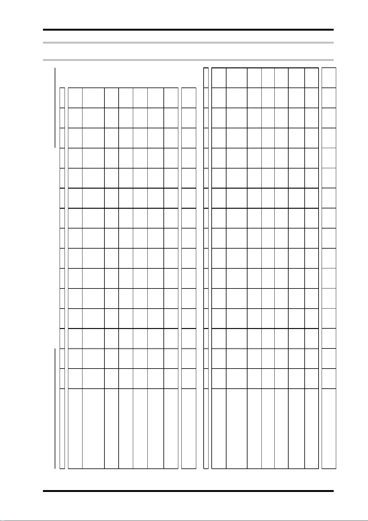
10 Inspection check sheet
Month & Year /
123456789101112131415
USG-400 INSPECTION CHECK SHEET (Please copy and use it)
USG-400 Serial nomber:
Power verification
Verification of communication cable
connection between compatible
electrosurgical generator and ultrasonic
generator (when using the
THUNDERBEAT
Verification of touch-screen and push
buttons
Verification of the THUNDERBEAT and
/ or SONICBEAT
Vrification of the high-frequency(RF
bipolar) output (when using the
Verification of footswitch connection
THUNDERBEAT)
Verification of the alarm system
Inspection 5-20 ISSUE1
16 17 18 19 20 21 22 23 24 25 26 27 28 29 30 31
e
on ca
ca
commun
on o
ca
er
Da
Power verification
connection between compatible
electrosurgical generator and ultrasonic
generator (when using the
Verification of touch-screen and push
buttons
Verification of the THUNDERBEAT and
/ or SONICBEAT
Verification of footswitch connection
Vrification of the high-frequency(RF
bipolar) output (when using the
THUNDERBEAT)
Verification of the alarm system
Inspector
Inspector
Page 59

USG-400
Chapter 6 : Safety check
1 Check procedures.............................................................................6-2
2 Check Card ........................................................................................6-6
ISSUE1 6-1 Safety check
Page 60

USG-400
1 Check procedures
1-1 Grounding Resistance confirmation
○ Criteria
The resistance between an accessible metal part of the USG-400 and the grounding
terminal of the meet must be 0.1Ω or less.
○ Inspection procedures
(1) Measure the resistance value between the inlet grounding terminal the exterior chassis
screw farthest from the inlet to apply 25A (non-loaded condition : 6A or less) for five to ten
seconds.
1-2 Ground leakage current confirmation
1-3 Enclosure leakage current confirmation
Chassis screw
Inlet grounding terminal
○ Criteria
The ground leakage current must not be over the value at the table 1-5.
○ Inspection procedures
(1) Make measurements at the grounding terminal of the inlet.
○ Criteria
The enclosure leakage current must not be over the value at the table 1-5.
○ Inspection procedures
(1) Make measurement at the exterior chassis screw farthest from the inlet.
USG-400
Chassis screw
Chassis screw
Safety check 6-2 ISSUE1
Page 61
1-4 Patient leakage current confirmation
○ Criteria
The patient leakage current must not be the value at the table 1-5.
○ Inspection procedures
(1) Turn off the power switch of USG-400.
(2) Connect the Leakage current measuring jig (SS0499) to USG-400, and then connect the
SONICBEAT Transducer with the SONICBEAT instrument (SB-0545PC or SB-0545IC)
attached to it to the opposite side.
Leakage current measuring
USG-400
USG-400
ISSUE1 6-3 Safety check
Page 62

USG-400
(3) Connect the Leakage current measuring jig (SS0499) to the Leakage current tester.
Safety check 6-4 ISSUE1
Page 63

(4) Place the probe tip of SONICBEAT instrument in water.
(5) Turn on the power switch of USG-400, and then measure the leak current when the
SONICBEAT is activating at level 3( either handswitch can be used)
Leakage current measuring
USG-400
1-5 Leakage current criteria
No Mode
1 Ground leakage current 500μA 1000μA
2 Enclosure leakage current 100μA
3 Patient leakage current 10μA 50μA
USG-400
Criteria
Normal condition Single fault condition
500μA(others)
300μA(UL Deviation)
ISSUE1 6-5 Safety check
Page 64

USG-400
2 Check Card
Date of check
Product
SN
Inspected by
Checked by
Inspection item Criteria
Grounding Resistance The resistance must be 0.1Ω Ω
Ground leakage
current
Enclosure leakage
current
Patient leakage
current
Normal Condition
Single Fault
Normal Condition
Single Fault
Normal Condition
Single Fault
500 μA
1000 μA
100 μA
500 μA
300 μA (UL Deviation)
AC 10 μA
DC 10 μA
AC 50 μA
DC 50 μA
Measurement
Equipment No.
result
μA
μA
μA
μA
μA
μA
μA
μA
Safety check 6-6 ISSUE1
Page 65

USG-400
Chapter 7 : Block Diagram
1 Block Diagram...................................................................................7-2
ISSUE1 7-1 Block Diagram
Page 66

USG-400
1 Block Diagram
Power inlet
THUNDERBEAT
footswitch socket
SONICBEAT
footswitch socket
DC/AC
converter
circuit
LINK-IN
connector
Control
circuit
LINK-OUT
connector
Oscillation
control circuit
Amplifier
Touch-screen
Ultrasonic
output
circuit
Transducer socket
(THUNDERBEAT)
Transducer socket
(SONICBEAT)
Block Diagram 7-2 ISSUE1
Page 67

USG-400
Chapter 8 : Troubleshooting
1 Troubleshooting................................................................................8-2
2 Error screen.......................................................................................8-3
3 Troubleshooting guide......................................................................8-3
4 Returning the ultrasonic generator for repair...............................8-22
ISSUE1 8-1 Troubleshooting
Page 68

USG-400
1 Troubleshooting
WARNING
If any irregularity is observed with the equipment, follow the below steps.
1. Immediately stop the procedure and remove any equipment from inside the
body cavity.
2. Immediately stop the procedure and remove any equipment from inside the
body cavity.
3. Check if any error window is displayed.
4. If an error window is displayed, first read Section 2, “Error screen” and
Section 3, “Troubleshooting guide” and take proper remedial actions
according to “What to do when an error code is displayed”
5. If no error window is displayed, take proper remedial actions according to
“What to do when no error code is displayed”
If the ultrasonicIf the ultrasonic generator does not work after the
touch-screen displays irregularity, turn the ultrasonic
generator OFF and then turn it ON again. Confirm that the
output level setting returns to the normal state.
Never use the ultrasonic generator on a patient when any
irregularity is observed with the equipment. Otherwise, the
system may not work properly and serious injury to the
patient, surgical staff and/or surgeon may result.
Troubleshooting 8-2 ISSUE1
Page 69

USG-400
2 Error screen
The error window is configured as shown below in Figure 8.1
Figure 8.1
Types of error codes
The error windows are displayed in one of the following six patterns.
Pattern 1 Target error code: U001-U014
Pattern 2 Target error code: U501-U502, U507
Pattern 3 Target error code: U504
Pattern 4 Target error code: U508, U513
Pattern 5 Target error code: U509, U510, U511, U512, U514, U601
Pattern 6 Target error code: U503, U505-506
3 Troubleshooting guide
ISSUE1 8-3 Troubleshooting
Page 70

USG-400
Pattern 1 Target error code: U001-U014
The error windows are displayed in one of the following five patterns.
Turn the ultrasonic generator OFF and ON again. If the error window is still
displayed, disconnect the power supply and contact Olympus.
Target error code: U006
Check if the THUNDERBEAT or SONICBEAT instrument and
transducer are connected firmly. If not, connect them firmly.
Turn the ultrasonic generator OFF and ON again. If the error window is
still displayed, disconnect the power supply and contact Olympus.
Target error code: U010-U014
The touch-screen, the handswitches, footswitch pedals, and push
buttons on the ultrasonic generator are disabled.
Perform the remedial actions in accordance with “What to do when an
error code is displayed”
If the error code is still displayed, disconnect the power supply and
contact Olympus (see Figure 8.2).
Figure 8.2
Pattern 2 Target error code: U501-U502,U507
The touch-screen, handswitches, footswitch pedals and push buttons
are disabled.
The “OK button” is illuminated when the error is cleared.
When the “OK button” is pressed, the error window disappears and the
display returns to the screen displayed before the error window was
generated (see Figure 8.3).
Troubleshooting 8-4 ISSUE1
Page 71

USG-400
Figure 8.3
Pattern 3 Target error code: U504
WARNING
Energy output is not available when the error window (U504: Probe damage
error) is displayed. In this case, perform the probe check. The output will become
available when the confirmation window (Activation OK) is displayed.
Remedial actions:
If the probe damage error occurs, do not turn OFF the
ultrasonic generator, and do not disconnect the transducer
plug from the transducer socket of the ultrasonic generator.
Otherwise, damage or detachment of the probe tip may result
and this may cause serious injury to the patient.
1. Probe check push button
Press the “PROBE CHECK push button” on the right side of the front panel
(see Figure 8.4).
The confirmation window (Probe Check) is displayed.
Figure 8.4
ISSUE1 8-5 Troubleshooting
Page 72

USG-400
2. Executing the probe check
With the grasping section open, press and hold the handswitch or footswitch
pedal for 3 seconds and then release it (see Figure 8.5)
The probe check starts.
The information window (Checking) is displayed.
When the check completes, the information window (Checking)
disappears and the probe check result is displayed.
Figure 8.5
To cancel the probe check before the execution, press the “Cancel button” on the
bottom left of the confirmation window (Probe Check).
The display returns from the confirmation window (Probe Check) to the
“All screen” or “Set screen”.The confirmation window (Probe Check) is displayed.
Figure 8.6
Troubleshooting 8-6 ISSUE1
Page 73

USG-400
3. Probe check result
When the confirmation window (Activation OK) is displayed, press the “OK
button” (see Figure 8.6).
The confirmation window (Activation OK) disappears and the “All screen” or
“Set screen” is displayed (see Figure 8.7).
Figure 8.7
When this error window is displayed, take proper measures following
pattern 5 in this chapter (see Figure 8.8).
Figure 8.8
ISSUE1 8-7 Troubleshooting
Page 74

USG-400
Pattern 4 Target error code: U508,U513
The touch-screen, handswitches, footswitch pedals, and push buttons
are available.
Do not press the “OK button”, but proceed to the remedial actions on the
error window or of “What to do when an error code is displayed”.
If the “OK button” is pressed without taking the remedial actions, the
error window disappears even when the error is not cleared.
After taking each remedial action, be sure to perform the operation in
Section 5.7, “Verification of the high-frequency (RF bipolar) output
(when using the THUNDERBEAT)” in Chapter 5, “Inspection”.
When the error window is not displayed after inspection, the error has
been cleared.
If the error window is still displayed, the error is not cleared. Take the
next remedial action.
Figure 8.9
Troubleshooting 8-8 ISSUE1
Page 75
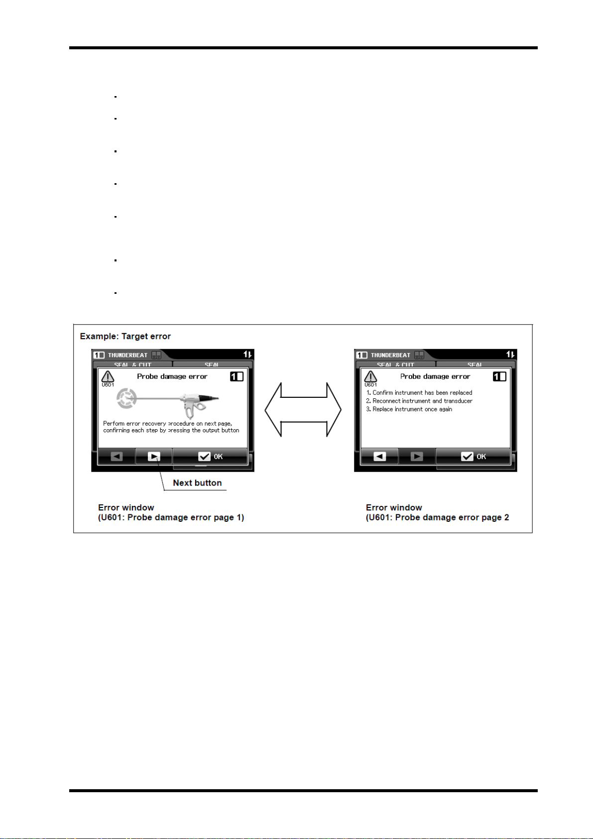
Pattern 5 Target error code: U509,U510,U511,U512,U514, and U601
The error messages have two screens.
The touch-screen, handswitches, footswitch pedals, and push buttons
are available.
Do not press the “OK button”, but pressing the “Next button”, perform to
the remedial actions on the error window.
If the “OK button” is pressed without taking the remedial actions, the
error window disappears even if the error is not cleared.
After taking each remedial action, be sure to perform the operation in
Section 5.7, “Verification of the high-frequency (RF bipolar) output
(when using the THUNDERBEAT)” in Chapter 5, ”Inspection”.
When the error window is not displayed after inspection, the error has
been cleared.
If the error window is still displayed, the error is not cleared. Take the
next remedial action.
USG-400
Figure 8.10
ISSUE1 8-9 Troubleshooting
Page 76

USG-400
Pattern 6 Target error code: U503,U505,U506
The touch-screen, handswitches, footswitch pedals, and push buttons
are available.
If the error is cleared, the error window disappears automatically.
If the error window is still displayed, take the next remedial action.
The error U505 has two pages for the remedial actions.
Figure 8.11
Troubleshooting 8-10 ISSUE1
Page 77

What to do when no error code is displayed
No error window is displayed and no alarm sounds in the following error status.
Perform the indicated remedial actions.
Irregularity Description Possible cause Remedial Actions
The ultrasonic generator
cannot be turned ON.
Energy output cannot be
generated.
The power cord is not connected. Connect the power cord.
The power cord is defective. Replace the power cord.
The power is not switched ON. Press the power switch to ON.
Ultrasonic generator malfunction. Contact Olympus.
The transducer is not connected. Connect the transducer.
Transducer malfunction. The transducer is abnormal. Immediately
remove the THUNDERBEAT and/or
SONICBEAT from the body cavity and
replace the transducer.
THUNDERBEAT or SONICBEAT
instrument is not connected.
THUNDERBEAT or SONICBEAT
instrument malfunction.
Footswitch is not connected. Connect the footswitch.
Footswitch malfunction. Check the footswitch operation by referring
The power is not switched ON. Press the power switch to ON.
Another instrument is generating
energy output.
Compatible electrosurgical
generator is generating the
output.
The touch-screen of the
compatible electrosurgical
generator is being operated.
The other handswitch on the
THUNDERBEAT or SONICBEAT
or footswitch pedal than the
intended one is being pressed
(no activation).
Connect the THUNDERBEAT or
SONICBEAT instrument.
The THUNDERBEAT or SONICBEAT
instrument is defective. Remove the
THUNDERBEAT and/or SONICBEAT from
the body cavity and replace the
THUNDERBEAT or SONICBEAT
instrument.
to Section 5.7, “Verification of the
high-frequency (RF bipolar) output (when
using the THUNDERBEAT)”. If it is
malfunctioning, replace it with a new one.
It is not permitted to generate outputs
simultaneously from two instruments.
Generate output from one instrument at a
time.
Stop using the compatible electrosurgical
generator (the THUNDERBEAT cannot be
used when the compatible electrosurgical
generator is in use).
Stop operating the touch-screen of the
compatible electrosurgical generator (the
THUNDERBEAT cannot be used when the
touch-screen of the compatible
electrosurgical generator is being
operated).
Release all of the switches.
USG-400
ISSUE1 8-11 Troubleshooting
Page 78

USG-400
Irregularity Description Possible cause Remedial Actions
The output cannot be
stopped.
THUNDERBEAT or SONICBEAT
instrument malfunction.
The THUNDERBEAT or SONICBEAT
instrument is defective. Remove the
THUNDERBEAT and/or SONICBEAT from
the body cavity and press the power switch
to OFF. Replace the THUNDERBEAT or
SONICBEAT instrument.
Transducer malfunction. The transducer is defective. Remove the
THUNDERBEAT and/or SONICBEAT from
the body cavity and press the power switch
to OFF.
Replace the transducer.
Footswitch malfunction. The footswitch is defective. Remove the
THUNDERBEAT and/or SONICBEAT from
the body cavity and press the power switch
to OFF.
Replace the footswitch.
Ultrasonic generator malfunction. Remove the THUNDERBEAT and/or
SONICBEAT from the body cavity and
press the power switch to OFF.
Contact Olympus.
be controlled.
An object is in contact with the
touch-screen.
Remove the object. The touch-screen cannot
The touch-screen remains
dark after switching the
ultrasonic generator ON
(start tone is audible after
switching ON).
does not react when a
push button on the front
panel is pressed during
standby.
The ultrasonic generator
does not react when a
(push) button on the front
panel is pressed.
No sound is audible
during activation.
Touch-screen malfunction. Remove the THUNDERBEAT and/or
SONICBEAT from the body cavity and
press the power switch to OFF.
Contact Olympus.
Touch-screen malfunction. Contact Olympus.
A push button is already pressed. Release the push button. The ultrasonic generator
Ultrasonic generator malfunction.
The (push) buttons are not
available during activation.
The volume is set to an inaudible
level (e.g. due to high
environmental noise).
Contact Olympus.
Release the footswitch or handswitch to
stop the activation.
Increase the volume either on the
touch-screen within the “Menu screen” or
use the volume control on the rear panel of
the ultrasonic generator.
Ultrasonic generator malfunction Stop using the ultrasonic generator and
press the power switch to turn OFF the
ultrasonic generator. Contact Olympus.
The error volume can not
The error volume is fixed.
No action required.
be adjusted.
The output volume can
Ultrasonic generator malfunction. Contact Olympus.
not be adjusted.
Troubleshooting 8-12 ISSUE1
Page 79

Irregularity Description Possible cause Remedial Actions
The output volume of
THUNDERBEAT can not
be adjusted.
The output volume of
THUNDERBEAT can not be
adjusted with the ultrasonic
Adjust the output volume of
THUNDERBEAT with the compatible
electrosurgical generator.
generator.
The ultrasonic generator
cannot be turned OFF.
Ultrasonic generator malfunction.
Remove the THUNDERBEAT and/or
SONICBEAT from the body cavity and press
the power switch to OFF. Contact Olympus.
USG-400
Automatic mist & smoke
Evacuation system/function
does not work.
Cutting/sealing/
coagulating does not work
properly.
The settings are erroneous. Correct the settings of the compatible high
The communication cable is not
connected.
flow insufflation unit.
Connect the communication
cable. ”Automatic mist & smoke
evacuationsystem/function (when using
the compatible high flow insufflation unit)”
The connection of the
communication cable is
erroneous.
Reconnect the communication cable.
“Automatic mist & smoke evacuation
system/function (when using the
compatible high flow insufflation unit)”.
Compatible high flow insufflation
Contact Olympus.
unit malfunction.
Ultrasonic generator,
communication cable or adapter
for UHI-2/3 malfunction
Remove the THUNDERBEAT and/or
SONICBEAT from the body cavity and
press the power switch to OFF. Contact
Olympus.
Operation is not appropriate.
Operate the instrument properly referring to
Chapter 4, “Operation” in the instruction
manual for THUNDERBEAT or SONICBEAT.
The treated site is not appropriate. Treat the adequate site referring to
Chapter 4, “Operation” in the instruction
manual for THUNDERBEAT or
SONICBEAT.
Carbonized tissue is present on the
grasping section or the probe tip.
The output level setting is not
appropriate.
Remove the carbonized tissue from the
grasping section or the probe tip with sterile
gauze or soft brush.
Set the adequate output level referring to
Chapter 3, “Preparation and Inspection” in
the instruction manual for THUNDERBEAT
or SONICBEAT.
Deterioration of the transducer. Confirm either whether one year has
passed since the transducer was delivered
or the use of the transducer has exceeded
100 cases. If it is applied to at least one of
them, replace the transducer with a new
one.
Not activating output.
Refer to “Energy output cannot be
enerated” of “What to do when no error
code is displayed” in Section 8.3,
“Troubleshooting guide”.
ISSUE1 8-13 Troubleshooting
Page 80

USG-400
Irregularity Description Possible cause Remedial Actions
Unintended output (burns)
Operation is not appropriate. Operate the instrument properly referring
to Chapter 4, “Operation” in the instruction
manual for THUNDERBEAT or
SONICBEAT (Also, see “Heat temperature
of the shaft” in the Appendix for details of
the temperature).
THUNDERBEAT or SONICBEAT
instrument malfunction.
The THUNDERBEAT or SONICBEAT
instrument is defective. Remove the
THUNDERBEAT and/or SONICBEAT from
the body cavity and press the power switch
to OFF. Replace the THUNDERBEAT or
SONICBEAT instrument.
Footswitch malfunction. The footswitch is defective. Remove the
THUNDERBEAT and/or SONICBEAT from
the body cavity and press the power switch
to OFF. Replace the footswitch.
Connection of the transducer with
THUNDERBEAT or SONICBEAT
instrument is loose.
Check if the THUNDERBEAT or
SONICBEAT instrument and transducer
are connected firmly. If not, connect them
firmly.
Transducer plug is not connected
to the THUNDERBEAT or
SONICBEAT socket properly.
Confirm that the transducer plug is
connected to the THUNDERBEAT or
SONICBEAT socket on the front panel of
the ultrasonic generator. If not, connect it
properly.
Transducer malfunction. The transducer is defective. Remove the
THUNDERBEAT and/or SONICBEAT from
the body cavity and press the power switch
to OFF. Replace the transducer.
Ultrasonic generator malfunction. Remove the THUNDERBEAT and/or
SONICBEAT from the body cavity and
press the power switch to OFF. Contact
Olympus.
Takes time to start up.
Shortage of power supply. Connect the equipment so that the total
capacitance of all equipment including the
ultrasonic generator connected to the
power outlet shall be smaller than that of
power supply.
Image of the touch-screen
is distorted.
The power cord is not connected.
Ultrasonic generator malfunction. Remove the THUNDERBEAT and/or
Image is distorted by noise
influence.
Connect the power cord.
SONICBEAT from the body cavity and press
the power switch to OFF. Contact Olympus.
Do not loop cords but separate them so
that they will not contact the main bodies
or cords of other medical electrical
equipment (electrocardiograph,
endoscopic video camera, etc.).
Troubleshooting 8-14 ISSUE1
Page 81

Irregularity Description Possible cause Remedial Actions
THUNDERBEAT and/or
SONICBEAT is/are not
identified.
Footswitch is not
identified.
Transducer plug is not connected to
the THUNDERBEAT or
SONICBEAT socket properly.
Transducer malfunction.
Ultrasonic generator malfunction. Remove the THUNDERBEAT and/or
The footswitch plug is not connected
to the footswitch socket properly.
Footswitch malfunction. The footswitch is defective. Remove the
Ultrasonic generator malfunction. Remove the THUNDERBEAT and/or
Confirm that the transducer plug is
connected to the THUNDERBEAT or
SONICBEAT socket on the front panel of the
ultrasonic generator. If not, connect it
properly.
The transducer is defective. Replace the
transducer.
SONICBEAT from the body cavity and press
the power switch to OFF. Contact Olympus.
Connect the footswitch plug to the footswitch
socket firmly.
THUNDERBEAT and/or SONICBEAT from
the body cavity and press the power switch
to OFF. Replace the footswitch.
SONICBEAT from the body cavity and press
the power switch to OFF. Contact Olympus.
USG-400
The transducer is heated. Transducer temperature is too
high due to continuous output.
Difficult to grasp tissue.
Opening and closing ofthe
grasping section is
stiff/can't open.
Operation is not appropriate. Operate the instrument properly referring to
The treated site is not appropriate. Treat the adequate site referring to Chapter
The grasping surface (white Teflon
surface) has been worn out.
Carbonized tissue is present on the
grasping section or the probe tip.
THUNDERBEAT or SONICBEAT
instrument malfunction.
Carbonized tissue is present onthe
grasping section or the probe tip.
THUNDERBEAT or SONICBEAT
instrument malfunction.
Stop output until the temperature cools down.
Chapter 4, “Operation” in the instruction
manual for THUNDERBEAT or SONICBEAT.
4, “Operation” in the instruction manual for
THUNDERBEAT or SONICBEAT.
If the grasping surface (white Teflon surface)
has been worn out, replace THUNDERBEAT
or SONICBEAT with a new one.
Remove the carbonized tissue from the
grasping section or the probe tip with sterile
gauze or soft brush.
The THUNDERBEAT or SONICBEAT
instrument is defective. Remove the
THUNDERBEAT and/or SONICBEAT from
the body cavity and press the power switch
to OFF. Replace the THUNDERBEAT or
SONICBEAT instrument.
ISSUE1 8-15 Troubleshooting
Page 82

USG-400
What to do when error code is displayed
Find the applicable error code from the following table and take the actions
indicated in “Remedial actions”.
Error Code
U001 USG-400
U002 USG-400
Irregularity
Description
generator error
(Configuration
malfunction)
generator error
(FPGA (software)
malfunction)
Possible cause Remedial Actions
Ultrasonic generator malfunction
due to the fail of the internal
circuitry of the ultrasonic
generator.
Same as the above. Same as the above.
Turn the ultrasonic generator OFF
and ON again. If the error window is
still displayed, contact Olympus.
U003 USG-400
generator error
(Output switch
circuit malfunction)
U004 USG-400
generator error
(Error circuit
malfunction)
U005 USG-400
generator error
(Handpiece
detection circuit
malfunction)
U006 USG-400
generator error
(Output detection
circuit malfunction)
U007 USG-400
generator error
(Memory damage)
Same as the above. Same as the above.
Same as the above. Same as the above.
Same as the above. Same as the above.
Connection of the transducer
with THUNDERBEAT or
SONICBEAT instrument is loose.
Ultrasonic generator malfunction
due to the fail of the internal
circuitry of the ultrasonic
generator.
Ultrasonic generator malfunction
due to the fail of the internal
circuitry of the ultrasonic
generator.
1.Check if the THUNDERBEAT or
SONICBEAT instrument and
transducer are connected firmly. If
not, connect them firmly.
2.Turn the ultrasonic generator OFF
and ON again. If the error window is
still displayed, contact Olympus.
Turn the ultrasonic generator OFF
and ON again. If the error window is
still displayed, contact Olympus.
U008 USG-400
generator error
(Touch-screen
malfunction)
Same as the above. Same as the above.
Troubleshooting 8-16 ISSUE1
Page 83

Error Code
U009 USG-400
U011 Cooling fan error
Irregularity
Description
generator error
(Calibration
malfunction)
USG-400
Possible cause Remedial Actions
Ultrasonic generator malfunction
due to the fail of the internal
circuitry of the ultrasonic
generator.
Ultrasonic generator malfunction.U010 Overcurrent error
Transducer malfunction.
Foreign object is caught in rear
cooling fan.
Ultrasonic generator malfunction. 2. If the error window is still displayed,
Turn the ultrasonic generator OFF
and ON again. If the error window is
still displayed, contact Olympus.
1.Turn the ultrasonic generator OFF
then ON again. Confirm instrument
activation.
2. If no output, replace transducer.
repeat step 1.
3. If the error window is still displayed,
contact Olympus.
1. Confirm a foreign substance object
is not caught in rear vent holes,
then turn the ultrasonic generator
OFF and ON again.
contact Olympus.
U012 Overheated circuit
error
U013 Touch-screen error
U014 Push button error
U501 Handswitch error
Fan entrance/exit is blocked. 1. Confirm vent holes are not covered
Ultrasonic generator malfunction. 2. If the error window is still displayed,
Touch-screen was pressed when
the ultrasonic generator was
turned ON.
Touch-screen malfunction (a
foreign substance object such as
dust may be stuck between the
touch-screen and front panel).
Touch-screen malfunction. 3. If the error window is still displayed,
A push button was pressed when
the ultrasonic generator was
turned ON.
Push buttons malfunction. 2. If the error window is still displayed,
Handswitch was pressed when
the ultrasonic generator was
turned ON.
by an obstacle, and then turn the
ultrasonic generator OFF and ON
again.
contact Olympus.
1. Turn the ultrasonic generator OFF
and ON again without touching the
touch-screen.
2. Remove the foreign substance
object and turn the ultrasonic
generator OFF and ON again.
contact Olympus.
1. Turn the ultrasonic generator OFF
and ON again without touching the
push button.
contact Olympus.
1. Turn the ultrasonic generator OFF
and ON again without touching the
handswitch.
Handswitch malfunction. 2. If the error window is still displayed,
replace the THUNDERBEAT or
SONICBEAT instrument.
Ultrasonic generator malfunction. 3. If the error window is still displayed,
contact Olympus.
ISSUE1 8-17 Troubleshooting
Page 84

USG-400
Error Code
U502 Footswitch error
Irregularity
Description
Possible cause Remedial Actions
Footswitch pedal was pressed
when the ultrasonic generator is
turned ON.
Footswitch malfunction. 2. If the error window is still displayed,
Ultrasonic generator malfunction. 3. If the error window is still displayed,
1. Turn the ultrasonic generator OFF
and ON again without pressing the
footswitch pedal.
replace the footswitch.
contact Olympus.
U503 System connection
error
U504 Probe damageerror
(which isdetected
during surgery)
U505 ESG communication
error
A unit with overlapped ID is
connected. Example: When two
compatible electrosurgical
generators are connected.
System connection malfunction. 2. If the error window is still displayed,
Cracked probe. Replace THUNDERBEAT or
Compatible electrosurgical
generator is not turned ON.
Communication cable to the
compatible electrosurgical
generator is not connected.
Communication cable wire
disconnection.
Ultrasonic generator malfunction. 4. Contact Olympus.
1. Confirm the system does not have
multiple same generators.
contact Olympus.
SONICBEAT without disconnecting
transducer plug. After replacement,
press the PROBE CHECK push
button to confirm that the new
instrument works normally.
1. Confirm the compatible
electrosurgical generator is
switched ON. If not, turn it ON.
2. Confirm the communication cable
of rear panel to the compatible
electrosurgical generator is
connected properly. If not, connect
it properly.
3. Replace the communication cable.
U506 ESG docking error
U507 Unsupported ESG
error
Compatible electrosurgical
generator is not connected.
Ultrasonic generator malfunction. 2. Contact Olympus.
The software version of the
connected compatible
electrosurgical generator is not
supported.
1. Confirm the compatible
electrosurgical generator is properly
connected. If not, connect it
properly.
Contact Olympus (Connected ESG
not supported by USG-400).
Troubleshooting 8-18 ISSUE1
Page 85

Error Code
U508 SEAL & CUT short
Irregularity
Description
circuit error
USG-400
Possible cause Remedial Actions
Output is generated while a
metallic object is grasped.
Output in body fluids. 2. Remove excess fluids in the body.
Grasping section wear. 3. If the error window is still displayed,
1. Confirm no metal object is grasped
between jaw and probe, then
confirm activation.
replace the THUNDERBEAT or
SONICBEAT instrument.
U509 Ultrasonic level error
Hard tissue (e.g., bone) is
caught.
Excessive load is applied to the
distal end.
Connection of the transducer
with THUNDERBEAT or
SONICBEAT instrument is loose.
Transducer plug is not
connected to the
THUNDERBEAT or SONICBEAT
socket properly.
Transducer malfunction. 5. Replace the transducer.
Probe damage or malfunction. 6. Replace the THUNDERBEAT or
Ultrasonic generator malfunction. 7. Contact Olympus.
1. Do not grasp the hard tissue.
2. Reduce force applied to distal end
of the probe.
3. Check if the THUNDERBEAT or
SONICBEAT instrument and
transducer are connected firmly. If
not, connect them firmly.
4. Confirm that the transducer plug is
connected to the THUNDERBEAT
or SONICBEAT socket on the front
panel of the ultrasonic generator. If
not, connect it properly.
SONICBEAT instrument.
ISSUE1 8-19 Troubleshooting
Page 86

USG-400
Error Code
U510 Ultrasonic
Irregularity
Description
frequency error
(which is detected
during surgery)
Possible cause Remedial Actions
Hard tissue (e.g., bone) is
caught.
Excessive load is applied to the
distal end.
1. Do not grasp the hard tissue.
2. Reduce force applied to distal end
of the probe.
U511 SEAL short circuit
error
Connection of the transducer
with THUNDERBEAT or
SONICBEAT instrument is loose.
Transducer plug is not
connected to the
THUNDERBEAT or SONICBEAT
socket properly.
Transducer temperature is too
high due to continuous output.
Transducer temperature is too
high due to use immediately after
autoclaving.
Transducer malfunction. 7. Replace the transducer.
Probe damage or malfunction. 8. Replace the THUNDERBEAT or
Ultrasonic generator malfunction. 9. Contact Olympus.
Output is generated while a
metallic object is touched.
Output in body fluids 2. Remove excess fluids in the body.
3. Check if the THUNDERBEAT or
SONICBEAT instrument and
transducer are connected firmly. If
not, connect them firmly.
4. Confirm that the transducer plug is
connected to the THUNDERBEAT
or SONICBEAT socket on the front
panel of the ultrasonic generator. If
not, connect it properly.
5. Stop output until the temperature
cools down.
6. Allow the transducer temperature to
cool.
SONICBEAT instrument.
1. Make sure that no metallic object is
grasped.
U512 Open circuit error
Grasping section wear. 3. If the error window is still displayed,
replace the THUNDERBEAT or
SONICBEAT instrument.
The fully assembly instrument is
activated without holding tissue.
Transducer and
THUNDERBEAT instrument are
not connected properly.
Transducer plug is not
connected to the
THUNDERBEAT socket
properly.
Transducer malfunction. 4. Replace the transducer.
The THUNDERBEAT instrument
malfunction.
Ultrasonic generator malfunction. 6. Contact Olympus.
1. Re-grasp tissue and confirm
activation.
2. Check if the THUNDERBEAT
instrument and transducer are
connected. If not, connect them
properly.
3. Confirm that the transducer plug is
connected to the THUNDERBEAT
socket on the front panel of the
ultrasonic generator. If not, connect
it properly.
5. Replace the THUNDERBEAT
instrument.
Troubleshooting 8-20 ISSUE1
Page 87

Error Code
U513 Time out error (SEAL
U514 Time out error
Irregularity
Description
& CUT, MAX, VAR)
(SEAL incomplete)
Possible cause Remedial Actions
Output time period is longer than
allowable by the system
(maximum output time: 60 s).
The specified output time period
has expired (maximum output
time: 15 s).
USG-400
The maximum output time period has
been expired. Re-grasp the tissue and
confirm activation.
Remove tissue or fluids from jaw and
probe. Re-grasp tissue and confirm
activation.
U601 Probe damage
error (which is
detected through
PROBE CHECK)
Cracked probe. 1. Confirm that the probe tip is not
broken. Press the PROBE CHECK
push button, open the grasping
section and confirm the normal
operation. If the probe is broken,
replace the THUNDERBEAT or
SONICBEAT instrument.
Excessive load is applied to the
distal end.
Connection of the transducer
with THUNDERBEAT or
SONICBEAT instrument is loose.
Transducer plug is not
connected o the
THUNDERBEAT or ONICBEAT
socket properly.
Transducer temperature is too
high due to use immediately after
autoclaving.
Transducer temperature is too
high due to continuous output.
Transducer malfunction. 7. Replace the transducer.
2. Reduce force applied to distal end
of the probe.
3. Check if the THUNDERBEAT or
SONICBEAT instrument and
transducer are connected firmly. If
not, connect them firmly.
4. Confirm that the transducer plug is
connected to the THUNDERBEAT
or SONICBEAT socket on the front
panel of the ultrasonic generator. If
not, connect it properly.
5. Allow the transducer temperature
cool prior to use.
6. Stop output until the temperature
cools down.
Probe damage or malfunction. 8. Replace the THUNDERBEAT or
SONICBEAT instrument.
Ultrasonic generator malfunction. 9. Contact Olympus.
ISSUE1 8-21 Troubleshooting
Page 88

USG-400
3 Returning the ultrasonic generator for repair
WARNING
When returning the ultrasonic generator for repair, contact Olympus. With the
ultrasonic generator, include a description of the malfunction or damage and the
name and telephone number of the individual at your location who is most
familiar with the problem. Include a repair purchase order.
Before returning the ultrasonic generator for repair, be sure
to disinfect it as described in Chapter 4, “Care, Storage, and
Disposal”. If the ultrasonic generator is not disinfected,
cross-contamination of the surrounding environment may
result.
Olympus will not assume any liabilities for human injuries or
equipment damage caused as a result of servicing or repair
by a person other than the Olympus qualified service
personnel.
Troubleshooting 8-22 ISSUE1
Page 89

Page 90

OLYMPUS MEDICAL SYSTEMS CORP.
2951 Ishikawa-cho, Hachioji-shi, Tokyo Japan
Engineering 2
Service Engineering Department
Service Division
PRINTED IN JAPAN FIRST EDITION : 11.2011 W186B
 Loading...