

Page 1

INSTRUCTIONS
HIGH DEFINITION LCD MONITOR
OEV261H
Page 2

Page 3

Contents
Contents
Labels and Symbols ..................................................................... 1
Important Information — Please Read Before Use.................... 3
Intended use ............................................................................................ 3
Instruction manual .................................................................................... 3
Instrument compatibility ........................................................................... 4
Repair and modification ........................................................................... 4
Signal words.............................................................................................. 5
Dangers, warnings and cautions .............................................................. 5
Outline....................................................................................................... 12
Chapter 1 Checking the Package Contents............................ 13
Chapter 2 Controls and Their Functions ................................ 14
2.1 Video monitor unit ........................................................................... 14
2.2 Front panel...................................................................................... 15
2.3 Rear panel ...................................................................................... 17
2.4 AC adapter...................................................................................... 19
Chapter 3 Installation and Connection ................................... 20
3.1 Installing the monitor....................................................................... 21
3.2 Installing the AC adapter................................................................. 23
3.3 Connection to an AC mains power supply ...................................... 24
Chapter 4 Inspection and Setup Before Use .......................... 26
4.1 Power supply .................................................................................. 26
4.2 Inspection of the displayed image................................................... 27
Chapter 5 Screen Menu and Operation of Front Panel.......... 28
5.1 PRESET button............................................................................... 28
5.2 INPUT button .................................................................................. 35
5.3 MENU button .................................................................................. 36
5.4 PIP button ....................................................................................... 38
5.5 POP button ..................................................................................... 39
5.6 SCAN button ................................................................................... 40
5.7 FUNCTION buttons (F1, F2/ENTER).............................................. 40
5.8 Status display.................................................................................. 41
High definition LCD monitor OEV261H
i
Page 4

Contents
Chapter 6 Submenu Operations .............................................. 44
6.1 INPUT CONFIG .............................................................................. 44
6.2 COMP. ............................................................................................ 46
6.3 VIDEO CONFIG .............................................................................. 48
6.4 WHITE BALANCE........................................................................... 49
6.5 VIDEO INPUT ................................................................................. 51
6.6 SYSTEM CONFIG .......................................................................... 62
6.7 FUNCTION...................................................................................... 64
6.8 WINDOW CONFIG ......................................................................... 66
6.9 REMOTE CONFIG.......................................................................... 71
6.10 CONTROL ...................................................................................... 73
Chapter 7 REMOTE Specifications .......................................... 75
7.1 GPI terminals .................................................................................. 75
Chapter 8 Care, Storage, and Disposal ................................... 78
8.1 Care ................................................................................................ 78
8.2 Storage ........................................................................................... 79
8.3 Disposal .......................................................................................... 79
Chapter 9 Inspections............................................................... 80
Chapter 10 Troubleshooting ...................................................... 81
10.1 Troubleshooting guide .................................................................... 81
10.2 Returning the monitor for repair ...................................................... 83
Appendix........................................................................................ 84
System chart ............................................................................................ 84
Transportation, storage, and operation environment/specifications.......... 90
EMC information........................................................................................ 94
Maintenance .................................................................................. 98
ii
High definition LCD monitor OEV261H
Page 5
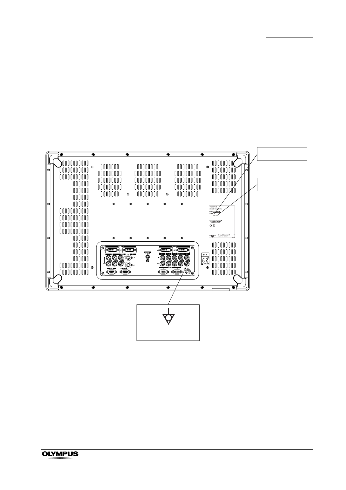
Labels and Symbols
Safety-related labels and symbols are attached to the instrument at the locations
shown below. If labels or symbols are missing or illegible, contact Olympus.
High definition LCD monitor
Labels and Symbols
Serial number
Electrical rating
Potential equalization
terminal
High definition LCD monitor OEV261H
1
Page 6
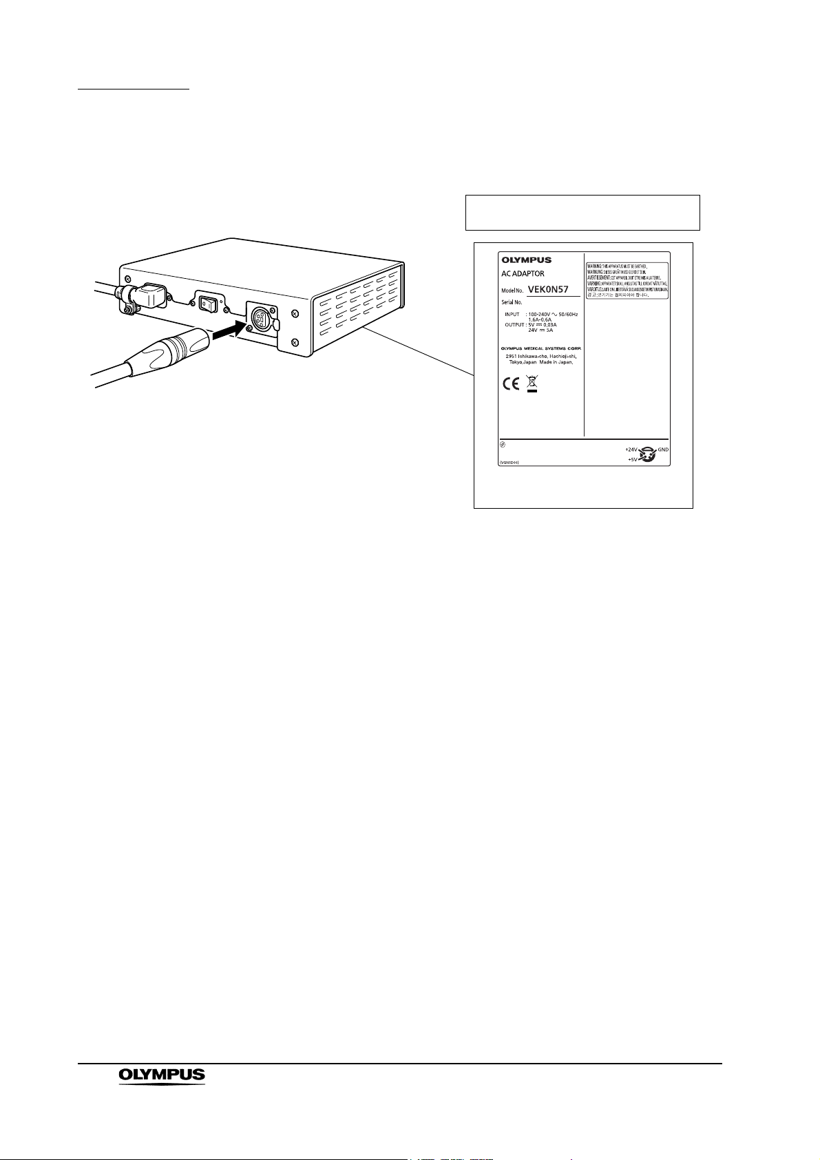
Labels and Symbols
AC adapter
The rating plate of the AC adapter is
on the underside of the adapter.
Serial number
Electrical rating
2
High definition LCD monitor OEV261H
Page 7

Important Information — Please Read Before Use
Important Information — Please Read
Before Use
Intended use
This instrument has been designed to be used with Olympus endoscopes, light
source, video system center, camera control units and endoscopic ultrasound
centers for endoscopic diagnosis and video observation.
Do not use this instrument for any purpose other than its intended use.
Instruction manual
This instruction manual contains essential information on using this instrument
safely and effectively. Before use, thoroughly review this manual and the
manuals of all equipment that will be used during the procedure and use the
equipment as instructed.
Keep this and all related instruction manuals in a safe, accessible location. If you
have any questions or comments about any information in this manual, please
contact Olympus.
Terms used in this manual
Video system center:
The video system center is a device that converts signals from a
videoscope or video converter into monitor images.
Camera control unit:
The camera control unit is a device that converts signals from a fiberscope
or rigid endoscope into monitor images.
Ultrasound center:
The ultrasound center converts the ultrasonic signals from an ultrasonic
endoscope or probe into monitor images.
Light source:
The light source provides light and electrical signals to the endoscope.
Wall mains socket outlet:
An electrical outlet that has a terminal used exclusively for grounding.
High definition LCD monitor OEV261H
3
Page 8

Important Information — Please Read Before Use
Aspect ratio:
It is a unit that expresses a rate of a screen side and a vertical length.
The aspect ratio of 4:3 is used usually for SDTV.
The aspect ratio of 16:9 is used usually for HDTV.
VESA mounting standards:
These are the standards to be applied when mounting an LCD panel on a
monitor mount or stand. These standards were defined by the Video
Electronics Standards Association (VESA), a US-based organization
concerned with computer display devices.
Mobile workstation:
The mobile workstation is a special trolley on which this monitor is placed.
PIP (Picture in Picture)
The sub display is put in the main display.
POP (Picture out Picture)
The sub display by the side of the main display.
Instrument compatibility
Refer to the “System chart” in the Appendix to confirm that this instrument is
compatible with the ancillary equipment being used. Using incompatible
equipment can result in patient or operator injury and/or equipment damage. It
may also impair the functionality of the instrument.
This instrument complies with medical electrical equipment edition 2
(IEC 60601-1-2: 2007). However when connecting with an instrument that
complies with medical electrical equipment edition 1 (IEC 60601-1-2: 1993), the
whole system complies with edition 1. (See, “EMC information” on page 94 for
EMC compliance level.)
Repair and modification
This instrument does not contain any user-serviceable parts. Do not
disassemble, modify or attempt to repair it; patient or operator injury and/or
equipment damage can result.
Some problems that appear to be malfunctions may be correctable by referring
to Chapter 10, “Troubleshooting”. If the problem cannot be resolved using the
information, contact Olympus.
4
High definition LCD monitor OEV261H
Page 9
Signal words
Important Information — Please Read Before Use
The following signal words are used throughout this manual:
Indicates an imminently hazardous situation which, if not
avoided, will result in death or serious injury.
Indicates a potentially hazardous situation which, if not
avoided, could result in death or serious injury.
Indicates a potentially hazardous situation which, if not
avoided, may result in minor or moderate injury. It may also
be used to alert against unsafe practices or potential
equipment damage.
Indicates additional helpful information.
Dangers, warnings and cautions
• Strictly observe the following precautions. Failure to do so
may place the patient and medical personnel in danger of an
electric shock:
− Keep fluids away from all electrical equipment. If fluids are
spilled on or into the monitor, immediately stop operating
it and contact Olympus.
− Do not prepare, inspect or use this instrument with wet
hands.
• Never install and operate this instrument in locations where:
− The concentration of oxygen is high.
− Oxidizing agents (such as nitrous oxide (N
present in the atmosphere.
O)) are
2
− Flammable anesthetics are present in the atmosphere.
Otherwise, explosion or fire may result because this monitor
is not explosion-proof.
High definition LCD monitor OEV261H
5
Page 10

Important Information — Please Read Before Use
• To reduce the risk of fire or shock hazard, do not expose this
• To reduce the risk of fire or shock hazard, keep this
• Do not use this instrument beyond the rated outlets and
• Always power the monitor with the voltage specified in this
• This product has a fluorescent lamp that contains a small
equipment to rain or moisture.
equipment away from all liquids. Use and store only in
locations which are not exposed to the risk of dripping or
splashing liquids, and do not place any liquid containers on
top of the equipment.
wiring, otherwise it may result in fire or an electrical shock.
manual. Supplying a nonspecified voltage to the monitor may
result in fire or an electric shock.
amount of mercury. It also contains lead in some
components. Disposal of these materials may be regulated in
your community due to environmental considerations. For
disposal or recycling information, please contact your local
authorities or the Electronics Industries Alliance.
• Strictly observe the following precautions for the power cord.
Damaging the power cord may result in fire or an electric
shock:
− When placing the power cord, take care that it is not
crushed in the space between the monitor and a wall,
mobile workstation or a shelf.
− Do not modify or damage the power cord.
− Do not stretch or place a heavy object on the power cord.
− Do not place the power cord near heating equipment or
expose it to excessive heat.
− Always grasp and pull the plug when unplugging the
power cord. Do not pull on the cord itself.
• Be sure to use the supplied AC adapter. Do not use the
supplied AC adapter for powering other devices. The
equipment may fail or the power cord may burn.
• If an irregularity is suspected during use of the instrument,
stop operation of the monitor. Some problems may be
correctable by referring to the following procedure. Damage
or irregularity in the instrument may compromise patient or
operator safety and may result in more severe equipment
damage.
6
High definition LCD monitor OEV261H
Page 11

Important Information — Please Read Before Use
− In case of a loss of the endoscopic image or a frozen
image:
Turn off the monitor, and turn on it again after 10 seconds.
Also turn off the ancillary equipment to be used in
combination with this monitor and turn on it again, as
described in the instruction manuals for the equipment. If
the problem cannot be resolved by the described remedial
action, stop using the monitor and gently withdraw the
videoscope, fiberscope, rigid endoscope or ultrasonic
endoscope from the patient’s body as indicated in the
endoscope’s instruction manual.
− In case other abnormalities:
Immediately stop operation of the monitor, withdraw the
videoscope, fiberscope, rigid endoscope or ultrasonic
endoscope from the patient as indicated in the
endoscope’s manual, and take remedial action as
described in Chapter 10, “Troubleshooting”. If the problem
cannot be resolved by the described remedial action, be
sure to contact Olympus for repair as described in Section
10.2, “Returning the monitor for repair” on page 83.
• When installing this instrument on the mobile workstation or a
trolley with a clamping table, be sure to provide the mobile
workstation or trolley with a toppling/movement prevention
measure. If such a measure is not taken, the mobile
workstation or trolley could move or fall during the procedure,
which could cause patient and/or operator injury.
• Before using high-frequency electrosurgical equipment,
make sure that any signal noise emitted from the equipment
does not affect the observation of the surgical procedures. If
high-frequency electrosurgical equipment is used without
such confirmation, patient injury may result.
• To prepare for unexpected equipment failure, be sure to
prepare spare equipment.
• It is recommended that only Olympus high-frequency
electrosurgical equipment be used with this unit.
Non-Olympus equipment can cause interference on the
monitor display or a loss of the endoscopic image.
• Always establish the system with equipment that complies
with relevant EMC standards for safety reasons. Equipment
which does not comply with EMC standards may cause
interference and its function or performance may be affected.
High definition LCD monitor OEV261H
7
Page 12

Important Information — Please Read Before Use
• To protect its components from excessive heat, the monitor
• Always use the power cord and connection cables that were
• Always use the monitor cables designated in this instruction
will turn itself OFF if its internal temperature rises to a level at
which equipment damage could occur. If this happens during
the procedure, immediately stop the examination and gently
withdraw the videoscope, fiberscope, rigid endoscope or
ultrasonic endoscope from the patient as indicated in the
endoscope’s instruction manual, and contact Olympus.
shipped with the monitor or mobile workstation. Using other
power cords or connection cables may result in an electric
shock or malfunction.
manual. Using non-designated monitor cables may result in
production of monitor noise at a level that may affect the
observation and treatment or loss of observation image.
• This apparatus must be grounded. To ensure safe operation,
the three-pin plug must be inserted only into a standard
three-pin power outlet which is effectively grounded through
normal household wiring.
• Extension cords used with the equipment must be three-core
and be correctly wired to provide connection to the ground.
Incorrectly wired extension cords can be extremely
hazardous.
• The fact that the equipment operates satisfactorily does not
imply that it is grounded, and the installation is not necessary
safe. For your safety, if in any doubt about the effective
grounding of the equipment or power outlet, please consult a
qualified electrician.
• Do not place the AC adapter in area accessible to the
patients. Ensure the patients cannot touch the device, as it
can reach high temperature under continuous use.
• In order to maintain adequate ventilation, do not install or
place this unit in a bookcase, built-in cabinet or any other
confined space. To prevent risk of electric shock or fire
hazard due to overheating, ensure that curtains and any
other materials do not obstruct the ventilation.
• When installing the instrument, reserve a space of 10 cm or
larger between the instrument and any walls or other
equipment. Lack of such a space will interfere with the
monitor’s internal cooling and may lead to malfunction or
equipment damage.
8
High definition LCD monitor OEV261H
Page 13

Important Information — Please Read Before Use
• This product has a fluorescent lamp that contains mercury.
Disposal may be regulated in your community due to
environmental considerations. For disposal or recycling
information, please contact your local authorities.
• Be sure that this instrument is not used adjacent to or
stacked with other equipment (other than the components of
this instrument or system) to avoid electromagnetic
interference.
• Electromagnetic interference may occur on this instrument
near equipment marked with the following symbol or other
portable and mobile RF (Radio Frequency) communications
equipment such as cellular phones. If electromagnetic
interference occurs, mitigation measures may be necessary,
such as reorienting or relocating this instrument, or shielding
the location.
• Do not install the instrument in a place exposed to direct
sunlight, high temperature (more than 60°C). Otherwise, it
may damage the cabinet or internal parts, result in fire.
• Be sure to plug the power cord securely, otherwise it may
result in fire and an electric shock.
• Unplug the power cord if the monitor is not used for a long
time. Otherwise, it may result in fire.
• Remove the dust on the plug of the power cord regularly,
otherwise it may result in fire and an electric shock.
• Be sure to turn the monitor OFF and unplug the power cord
before proceeding to maintain the monitor. If the power cord
is left plugged in, an electric shock may result.
• Check the installation at least once a year. An improper
installation could cause the monitor to fall off resulting in
personal injury.
• To reduce the risk of fire or shock hazard and annoying
interference, use the recommended accessories only.
• Attach this instrument to the wall by professional company
only. Otherwise, this instrument may fall due to improper
attachment, injury may result.
• Remove the wall-hanging bracket when not used. Otherwise
people moving in the vicinity of the monitor could get caught
on the bracket and be injured.
High definition LCD monitor OEV261H
9
Page 14
Important Information — Please Read Before Use
• When installing this instrument, be sure to attach it securely
• Do not move the monitor while the power cord and
• When installing or using the monitor, take care not to strike
• Install this instrument in a stable location. Otherwise, the
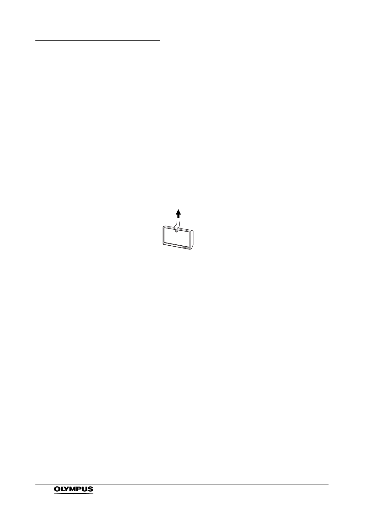
• Do not try to lift the monitor by grabbing the panel.
to the monitor mount. Otherwise, the instrument may fall.
This may cause patient and/or operator injury and may
damage the instrument.
connection cables are connected. Otherwise, damage to the
monitor, power cord and connection cables, fire or an electric
shock may result.
against a corner of the monitor. Otherwise, injury may result.
instrument may fall. This may cause operator injury and may
damage the instrument.
WRONG
• Do not expose the LCD panel to heavy pressure or pressure
from pointed objects. Take care especially during
transportation. Exposing the LCD panel to heavy pressure
may result in blurring or other damage.
• This monitor is intended for use in an electromagnetic
environment specified in “EMC information” on page 94.
• Exposing the LCD screen to intense light sources will impair
its characteristics and lower image quality.
• The mains plug of the power supply cord shall remain readily
operable. The AC receptacle (mains socket outlet) shall be
installed near the equipment and shall be easily accessible.
• To completely disconnect this equipment from the power AC
mains, disconnect the power cord plug from the AC
receptacle.
10
• In an environment exposed to drastic temperature
fluctuations, condensation may build up on inside the LCD
screen. This may lower the quality of the screen and may
damage it.
High definition LCD monitor OEV261H
Page 15

Important Information — Please Read Before Use
• The LCD screen is manufactured to precise specifications.
Although over 99.99% of the pixels function normally, 0.01%
of the pixels are either missing or constantly lit (red, blue or
green). This is normal and not a cause for concern.
• The liquid crystal protection panel is a specially
manufactured component. Wiping it with a hard cloth, or
rubbing it vigorously will scratch the surface.
• If a still image is displayed for an extended period of time, it
may generate a temporary afterimage (phosphor burn-in).
(However, such images can be removed by displaying
normal video for awhile.)
• The response speed and brightness of liquid crystal varies
with ambient temperatures.
• Some video images may appear blurred on the screen.
• Leaving the unit in a location exposed to high temperature
and humidity for an extended period of time may damage the
LCD screen and cause blurring.
• This monitor may become hot after an extended period of
operation, but this does not indicate a malfunction.
• High-frequency electrosurgical equipment can cause slight
interference on the monitor display.
High definition LCD monitor OEV261H
11
Page 16

Important Information — Please Read Before Use
Outline
The 26 inch OEV261H LCD display panel has been designed for use as a
medical monitor. The OEV261H is an LCD monitor designed to be used with
Olympus endoscopes, light sources, video system centers, camera control units
and ultrasound centers. Do not use the monitor for any other purpose.
Designed for medical applications
• Complies with IEC 60601-1 (Ed.2 and 3) and IEC 60601-1-2 (Ed.3)
• Sheet switches and the protective screen panel have been specifically
designed for use in the medical field.
WUXGA (1920 × 1200 pixels) high-resolution IPS LCD panel
10-bit 3DLUT (look-up-table) for accurate color reproduction
10-bit signal processing for smooth color transitions
Instant output of input signals
• The OEV261H incorporates a function that eliminates time delay of field
units caused by IP conversion minimizing delays between input and
image display.
Supports multiple formats
• Capable of handling SDI (both HD and SD), VIDEO, Y/C, YP
and DVI-D video input signals.
• Supports both NTSC and PAL TV systems.
• It supports computer (COMP) input signals such as analog signal input
via RGB and HD15 terminals as well as digital signal input via DVI-D
terminal.
A host functions
• PIP (Picture in Picture) and POP (Picture out Picture) dual screen display
functions
• ENDOSCOPE, 1.8,1.95, 2.0, 2.2, 2.4, 2.6, and PACS gamma
• Upside-down (180° rotation) and reverse (flip horizontal) functions
• GPI and RS-232C external control functions
BPR
/RGB
12
High definition LCD monitor OEV261H
Page 17
Chapter 1 Checking the Package Contents
Chapter 1 Checking the Package
Contents
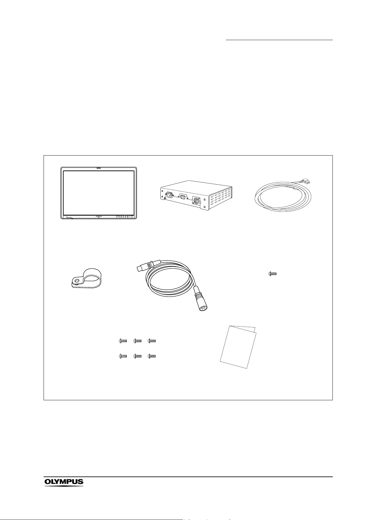
Match all items in the package with the components shown below. Inspect each
item for damage. If the instrument is damaged, a component is missing or, you
have any questions, do not use the monitor; immediately contact Olympus.
High definition LCD monitor
(OEV261H)
Power cord hook
Screw (for attaching LCD arm)
6pcs
DC cord
AC adapter
Power cord
Screw (for securing power cord)
1pcs
Instruction manual
High definition LCD monitor OEV261H
13
Page 18
Chapter 2 Controls and Their Functions
Chapter 2 Controls and Their Functions
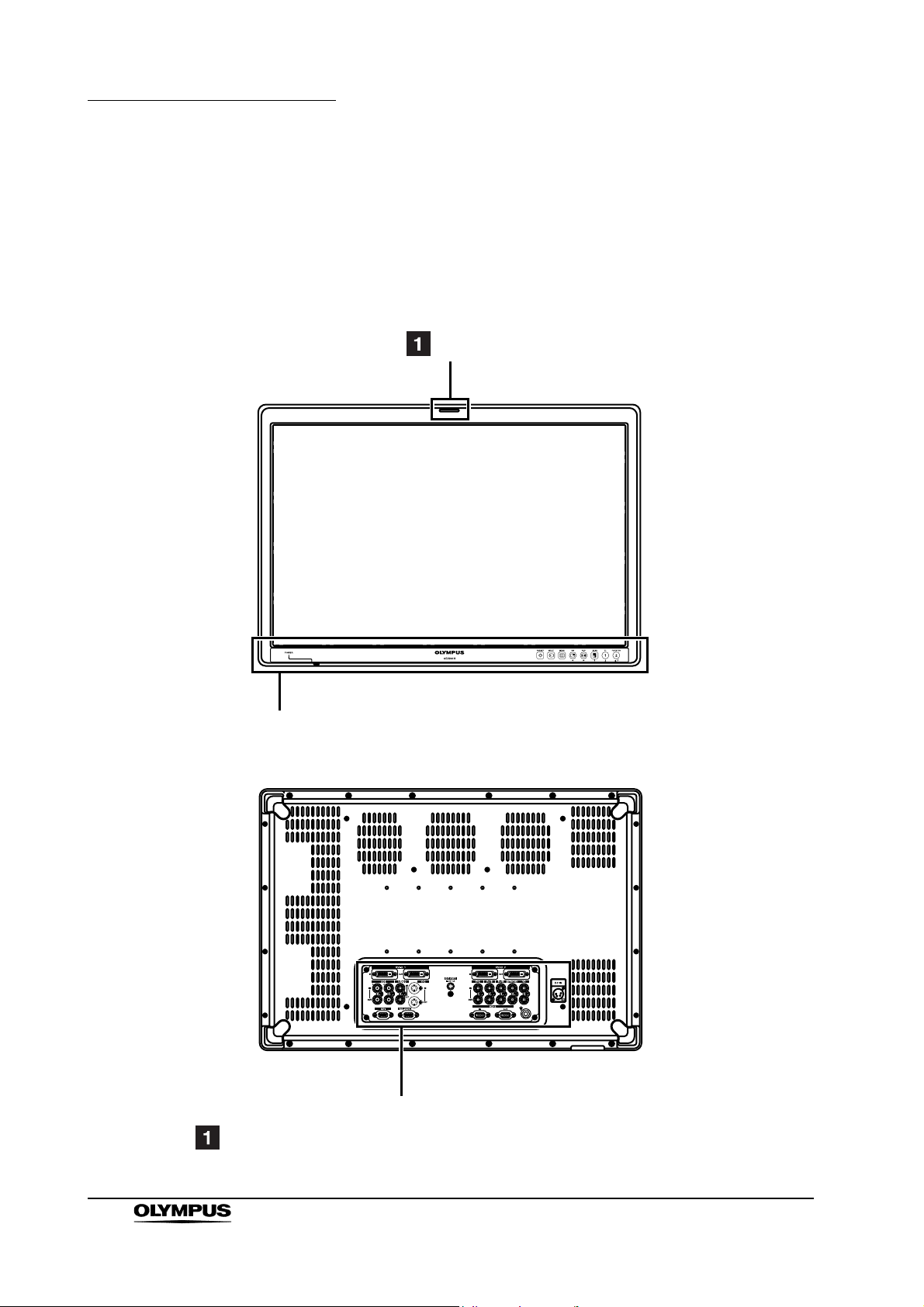
2.1 Video monitor unit
Front
Rear
Tally
Front panel (page 15)
14
Rear panel (page 17)
Tally lamp
When a LCD panel backlight or inverter circuit is malfunctioning, the lamp flashes orange.
High definition LCD monitor OEV261H
Page 19
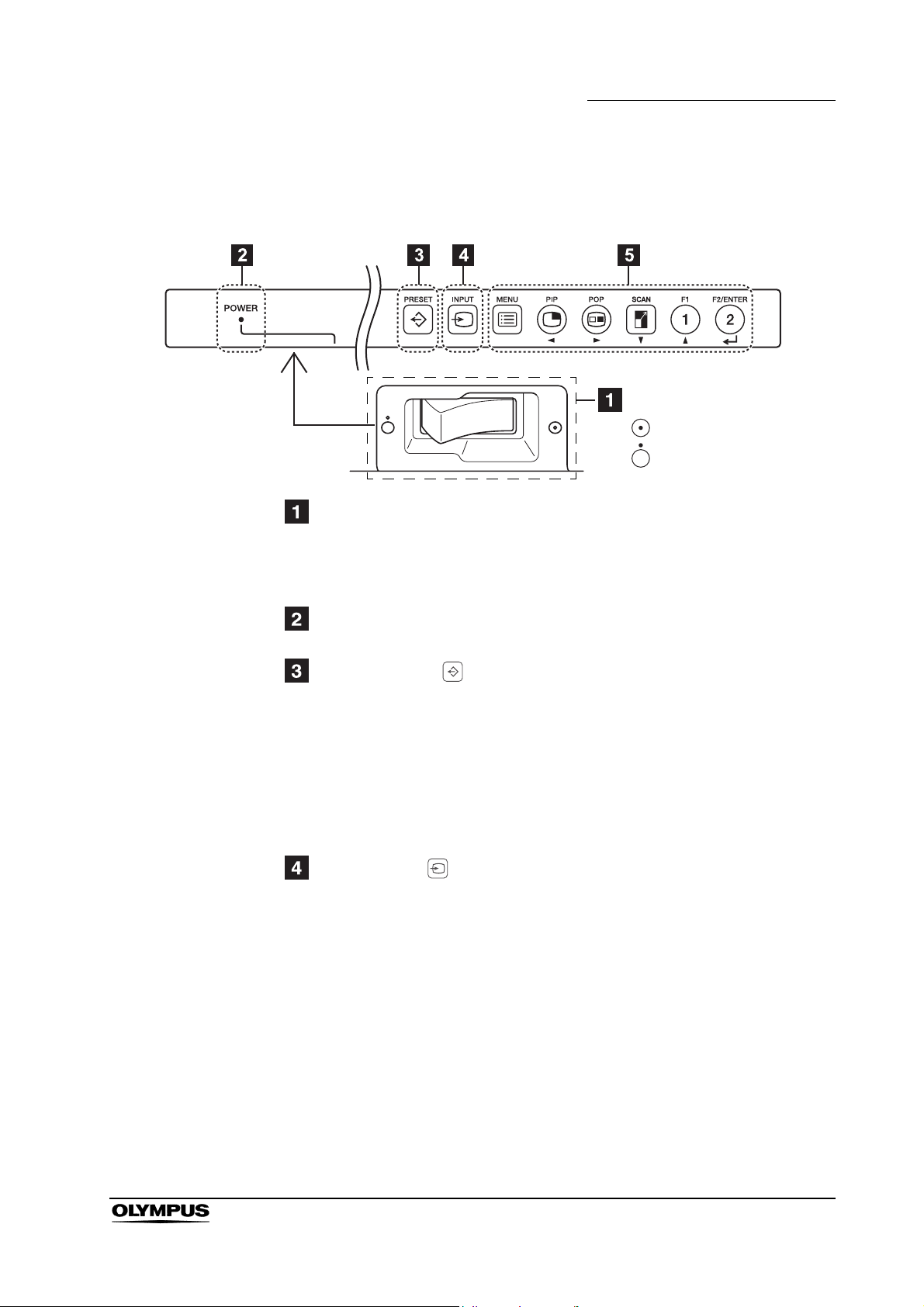
2.2 Front panel
POWER switch (the POWER switch is located at the bottom)
This switch turns the power On and Off.
Chapter 2 Controls and Their Functions
POWER switch
Turns the power on.
Turns the power off.
∗ Operates only when the AC POWER switch on the AC adapter is set to
On and the AC adapter operates.
POWER LED
When the power goes On, the LED (green) lights.
PRESET button ( )
Previously recorded input settings and image quality settings can be
selected from PRESET (10 settings), USER (20 settings) and FACTORY
(one setting).
PRESET : Settings made at the factory
USER : Settings saved by the user in the SYSTEM CONFIG
menu.
FAC TORY : Factory default settings
INPUT button ( )
Selects the input terminal for PORT A and PORT B signals. Two images
displayed in PIP or POP are called PORT A and PORT B in this manual.
High definition LCD monitor OEV261H
15
Page 20
Chapter 2 Controls and Their Functions
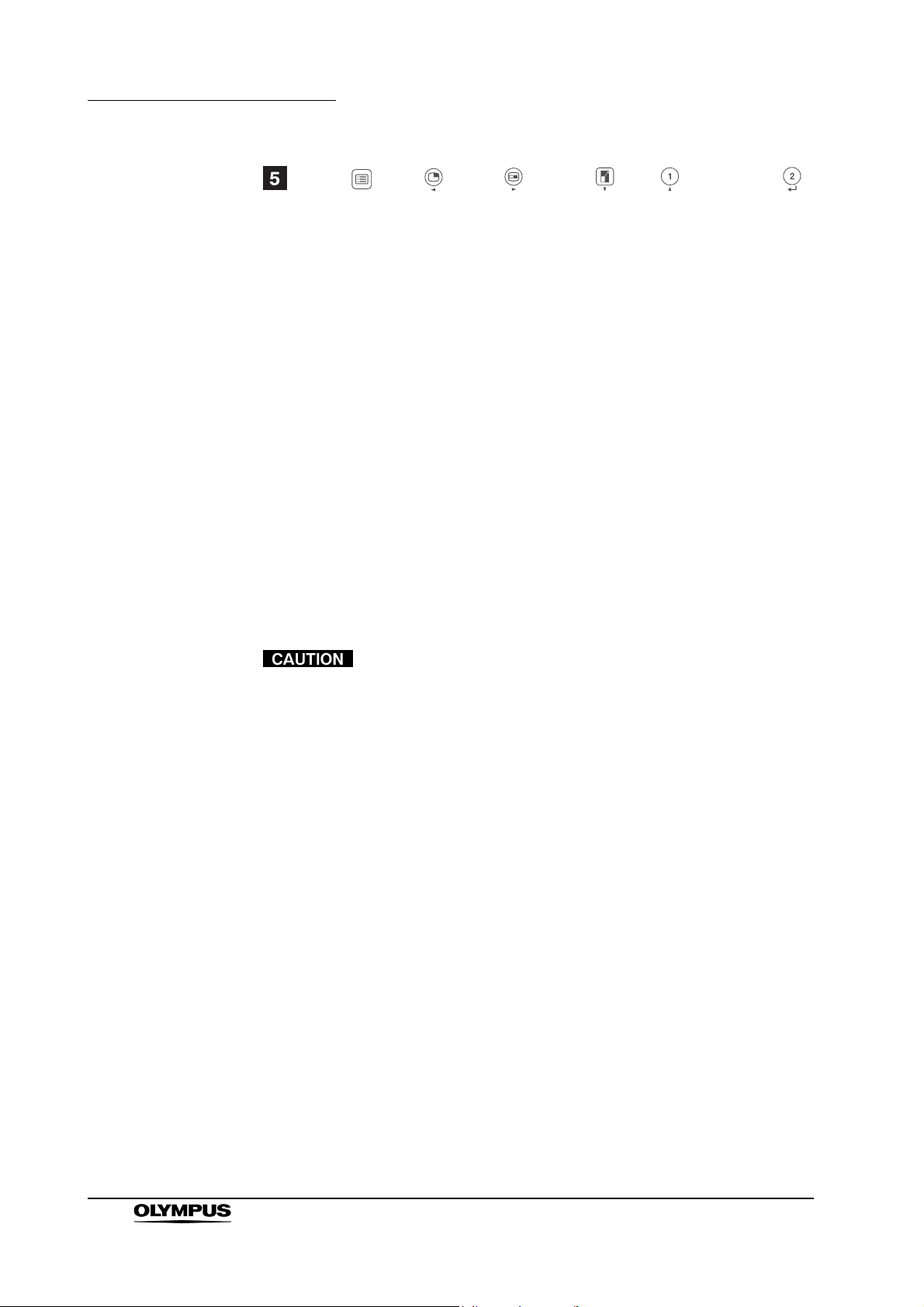
MENU ( ), PIP ( ), POP ( ), SCAN ( ), F1 ( ), F2/ENTER ( )
button
Use these buttons to display menus, select and adjust settings and confirm
menu selections.
MENU : Displays and exit menus.
PIP : Switches from the normal screen, dual PIP screen and
POP : Switches from the normal display to the dual POP screen
SCAN : Magnifies the single screen display and the large screen
F1 : Executes (confirms) items assigned to FUNCTION1 in a
F2/ENTER : Executes (confirms) items assigned to FUNCTION2 in a
PIP mode. When a menu is open, it moves the cursor to
the left and selects items.
and to POP mode. When a menu is open, it moves the
cursor to the right and selects items.
in PIP mode. When a menu is open, it moves the cursor
downwards and selects items.
menu. When a menu is open, it moves the cursor
upwards and selects items.
menu. Press to confirm settings in a menu or to go to a
submenu.
The buttons are made of plastic film. Do not use pointed
objects such as fingernails, pens or screwdrivers to press the
buttons, as the resulting damage or deformation could
prevent proper contact.
16
High definition LCD monitor OEV261H
Page 21
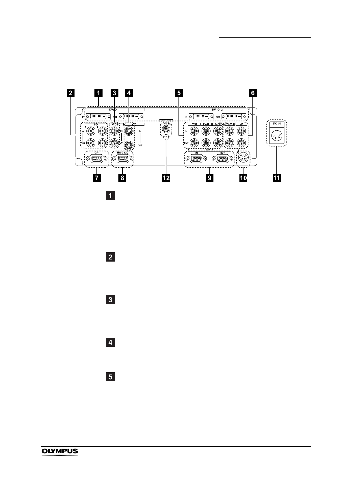
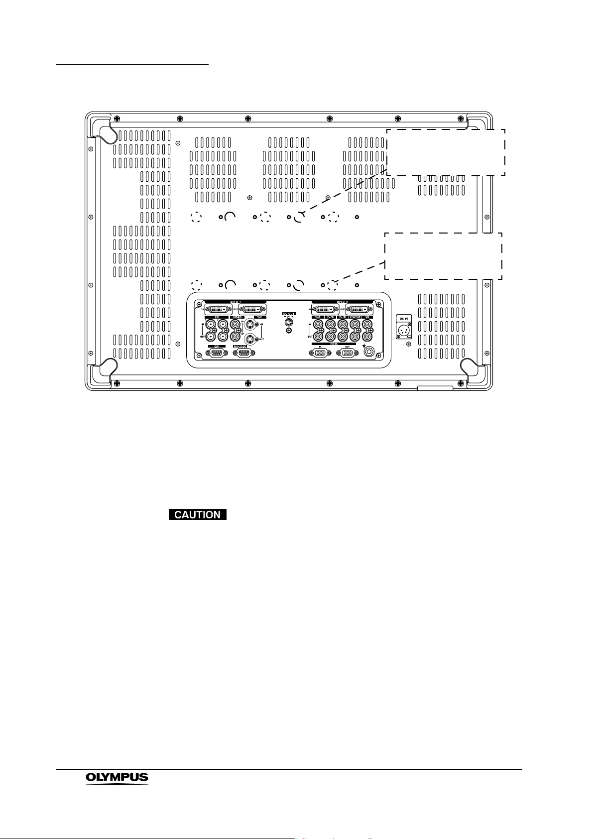
2.3 Rear panel
Chapter 2 Controls and Their Functions
DVI-D1, DVI-D2 terminals (DVI-D)
(It is compatible with DVI-VIDEO and DVI-COMP.)
IN : This is the DVI-D signal input terminal. (It is compatible with
DVI-VIDEO and DVI-COMP.)
OUT : This is the DVI-D output terminal. It is output when a DVI-D
input signal image appears on the display. It is not output when
other signals than DVI-D are selected.
SDI1, SDI2 terminals (BNC)
IN : This is the SDI input terminal (supports automatic HD and SD
switching).
OUT : This is the SDI output terminal. When the power goes On, an
SDI input signal is output at all times.
VIDEO terminal (BNC)
∗1
IN : This is the VIDEO signal (composite signal) input terminal.
OUT : This is the VIDEO signal output terminal. Regardless of On/Off
of the power supply, the VIDEO input signal is output at all
times.
Y/C terminal (4-pin mini-DIN)
IN : This is the Y/C signal input terminal.
OUT : This is the Y/C output terminal. When the power goes On, the
Y/C input signal is output at all times.
YP
/RGB terminal (BNC)
BPR
IN : This is the YP
∗1∗3
/RGB signal input terminal.
BPR
OUT : This is the input signal output terminal. Regardless of On/Off of
the power supply, the YP
/RGB input signal is output at all
BPR
times.
High definition LCD monitor OEV261H
17
Page 22
Chapter 2 Controls and Their Functions
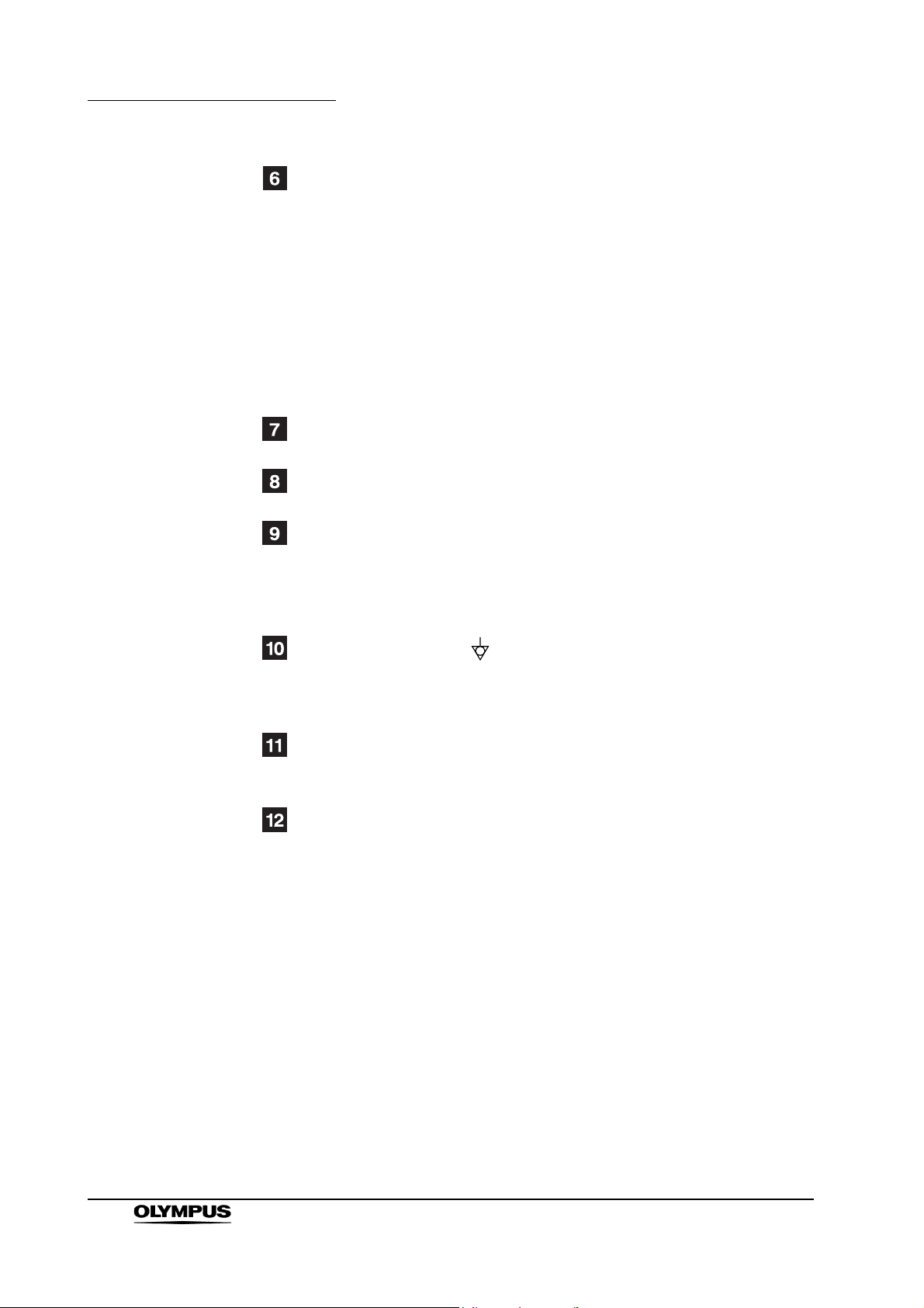
SYNC/HD, VD terminal (BNC)
∗2
IN : This is the input terminal for external synchronizing SYNC/HD,
VD signals.
OUT : This is the input signal output terminal. Regardless of On/Off of
the power supply, external synchronizing SYNC/HD, VD signals
are output at all times.
∗ An external synchronizing signal cable can be connected to the
SYNC/HD terminal.
When using RGB signals from a computer, connect the horizontal
synchronizing signal cable to the SYNC/HD terminal and the vertical
synchronizing signal cable to the VD terminal.
GPI input terminal (D-SUB 9-pin)
External control is possible by using a GPI signal.
RS-232C input terminal (D-SUB 9-pin)
External control is possible by using an RS-232C signal.
HD15 terminal (HD15)
IN : This is the COMP. signal input terminal.
OUT : This is the input signal output terminal. It is output when an
HD15 input signal image appears on the display. It is not output
when other signals than HD15 are selected.
Equipotential terminal ( )
This terminal is used to equalize potential.
When potential equalization is required, connect this terminal to the
potential equalization terminal of the equipment.
DC IN terminal (XLR 4-pin)
This is the 24 V DC/5 V DC input terminal. Connect the supplied DC cord of
the supplied AC adapter to this terminal.
DC OUT terminal (special 4-pin)
This is the 5 V DC output terminal. When a DVI-FIBER adapter is connected
to DVI-D 2 IN, use the designated cable to connect this terminal to the
power terminal of the adapter.
∗1: Unless a cable is connected to the OUT terminal, the IN terminal is
automatically terminated at 75
terminal releases the 75
Ω
. Since a connection to the OUT
Ω
termination of the unit, the level of the
VIDEO signal input to the unit may become too large depending on the
connected device.
∗2: Unless a cable is connected to the OUT terminal, the IN terminal is
automatically terminated at 1 k
terminal will automatically release the 1 k
Ω
. Making a connection to the OUT
Ω
termination.
18
∗3: When a device is connected to the OUT terminal, 1080p and computer
input and other broadband signals may distort character outlines and
other details.
High definition LCD monitor OEV261H
Page 23
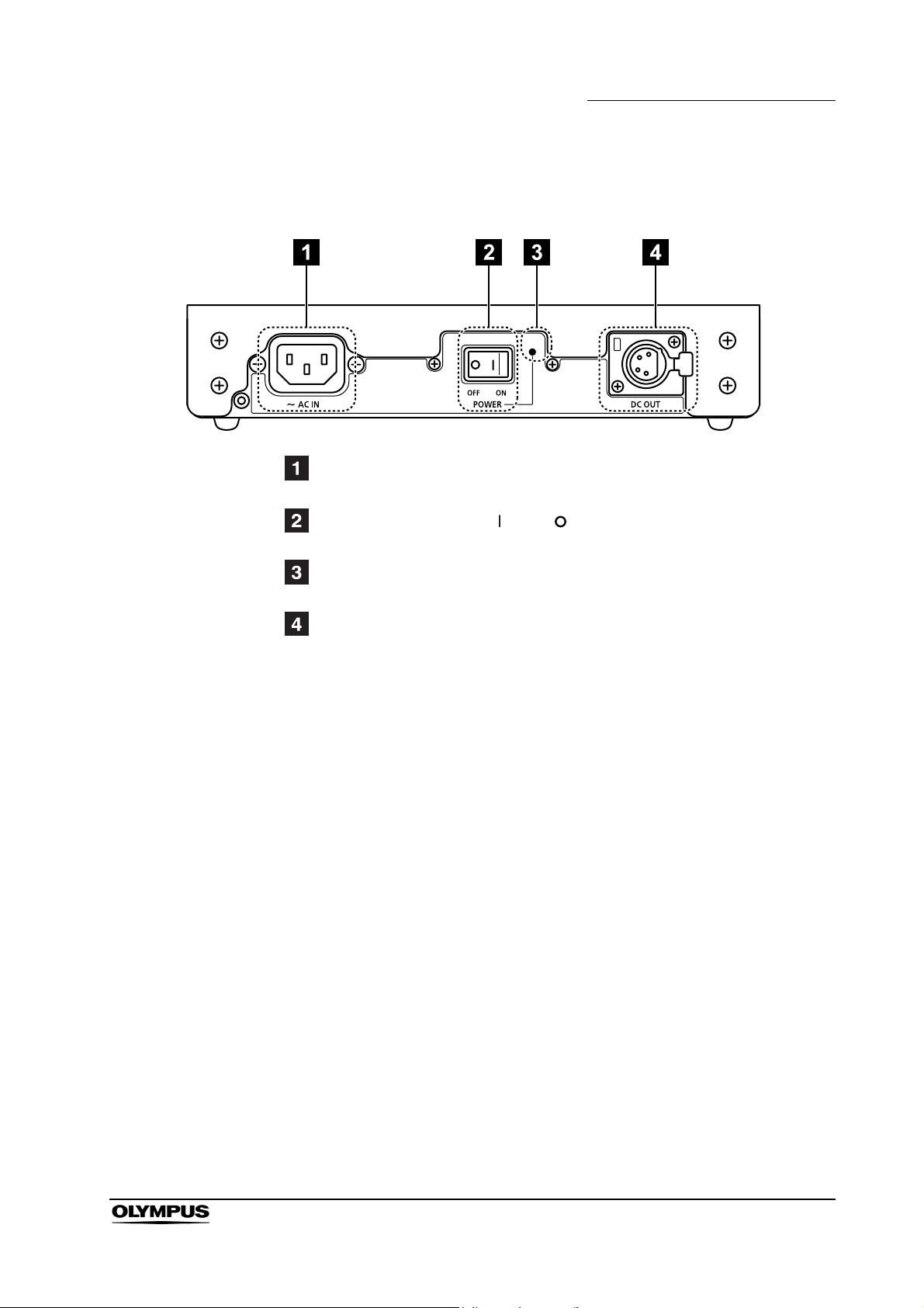
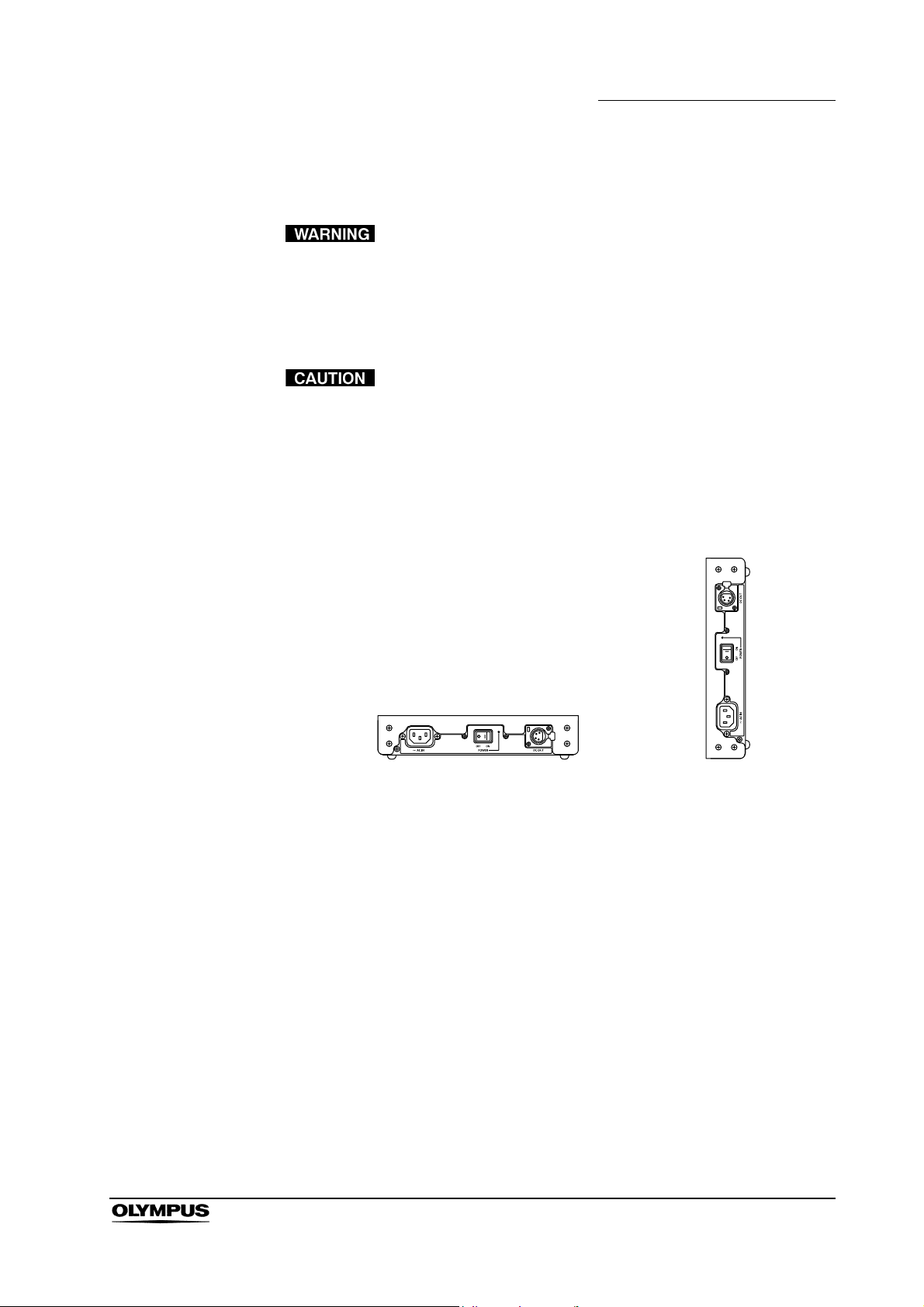
2.4 AC adapter
AC IN terminal
This is the AC input terminal.
AC POWER switch (ON: , OFF: )
This switch turns the AC adapter on and off.
Chapter 2 Controls and Their Functions
AC POWER LED
This lamp lights green when the AC POWER switch is set to on.
DC OUT terminal
This is the DC output terminal.
This terminal enables connection of a DC cord.
High definition LCD monitor OEV261H
19
Page 24
Chapter 3 Installation and Connection
Chapter 3 Installation and Connection
Review this chapter thoroughly before each use. If the
equipment is not properly prepared before each use,
equipment damage, patient and operator injury and/or fire
can occur.
• Turn OFF all system components before connecting them.
Otherwise, equipment damage can result.
• Use appropriate cables. Otherwise, equipment damage or
malfunction can result.
• Use the monitor under the conditions described in the section
“Transportation, storage, and operation
environment/specifications” in the Appendix. Otherwise,
improper performance, compromised safety and/or
equipment damage may result.
• The cables should not be sharply bent, pulled, twisted or
crushed.
• Should the LCD panel of the monitor break, never touch it
with bare hands; injury could occur. If your hands come in
contact with the liquid crystal material, be sure to rinse them
off thoroughly with water.
• The HDTV monitor remote cable (MAJ-1161, MAJ-1230) is
connected to a “GPI” terminal. If this is connected to a
“RS-232C” terminal, it may lead to malfunction or equipment
damage.
Prepare this monitor and compatible equipment (shown in the “System chart” in
the Appendix) before each use, and refer to the instruction manuals of each
system component. Install and connect the equipment as following pages.
20
High definition LCD monitor OEV261H
Page 25

3.1 Installing the monitor
• The monitor is heavy; care must be taken when installing it.
Otherwise, injury to the installer(s) and/or damage to the
instrument may result.
• When installing the instrument, reserve a space of 10 cm or
larger between the instrument and any walls or other
equipment. Lack of such a space will interferes with the
monitor’s internal cooling and may lead to malfunction or
equipment damage.
• Do not install this monitor near a source of strong
electromagnetic waves (such as a microwave or short-wave
therapy machine, MRI equipment, radio equipment or cellular
phone). Otherwise, electromagnetic noise may interfere with
the monitor image.
Chapter 3 Installation and Connection
Installation on a mobile workstation
When using a LCD monitor mount, prepare a 100 × 200 mm or 100 × 100 mm
monitor mount that complies with VESA mount standards.
Fix the monitor onto a 100 × 200 mm monitor mount using the six screws
provided. Or fix the monitor onto a 100 × 100 mm monitor mount using the four
screws provided. For installation procedures, refer to the instruction manual for
the monitor mount.
High definition LCD monitor OEV261H
21
Page 26
Chapter 3 Installation and Connection
100 × 100 mm
Screw hole for attaching
LCD arm
(for VESA)
100 × 200 mm
Screw hole for attaching
LCD arm
(for WVESA)
1. Align the LCD monitor mount mounting screw holes on the rear of the
instrument with the mounting screw holes on the LCD monitor mount
(see upper figure).
2. Fix the monitor onto the LCD monitor mount using the six screws
provided with the monitor.
• Ensure that the monitor is fixed firmly to the LCD monitor
mount. Otherwise, the monitor may drop and cause injury to
the operator or damage the monitor.
• Use a monitor mount with sufficient load resistance to
support the weight of the monitor. If the monitor falls, patient
or operator injury and/or equipment damage may result.
• Do not use screws other than those provided with the LCD
monitor. Otherwise, the monitor cannot be fixed firmly to the
LCD monitor mount and the monitor may drop, causing injury
to the operator or damage the LCD monitor.
• Do not install the monitor on mobile workstations other than
those listed in this instruction manual. Otherwise, the mobile
workstation may tip, injury to the operator or damage of the
monitor/equipment on the mobile workstation may result.
22
High definition LCD monitor OEV261H
Page 27
3.2 Installing the AC adapter
Keep fluids away from the AC adapter. Failure to do so may
place the patient and medical personnel in danger of an
electric shock.
Install the AC adapter in the level position in a dry and stable location.
• Install this instrument in a stable location. Otherwise, the
instrument may fall. This may cause operator injury and may
damage the instrument.
• Do not install this instrument in vertical position. Otherwise,
the fluid or dust is into this instrument, fire or an electric
shock may result.
Chapter 3 Installation and Connection
Level position: correct Vertical position: incorrect
• This instrument may become hot after an extended period of
operation. Do not place heat-sensitive material near this
instrument.
High definition LCD monitor OEV261H
23
Page 28
Chapter 3 Installation and Connection
3.3 Connection to an AC mains power supply
Use only a grounded wall mains outlet when connecting the
monitor. Failure to do so may cause an electric shock or fire.
• Do not allow the power cord to become wet. A wet power
cord may cause an electric shock.
• Confirm that the wall mains outlet or the mobile workstation
has adequate electrical capacity. Failure to do so may cause
fire or power fluctuation.
• Use of a power supply with insufficient electrical capacities
may cause malfunction of the equipment.
• Be sure to connect the power plug securely. Otherwise, the
equipment will not function.
• Do not bend, pull or twist the power cord. An electric shock,
equipment damage or fire can result.
• Be sure to use the supplied AC adapter. Do not use the
supplied AC adapter for powering other devices. The
equipment may fail or the power cord may burn.
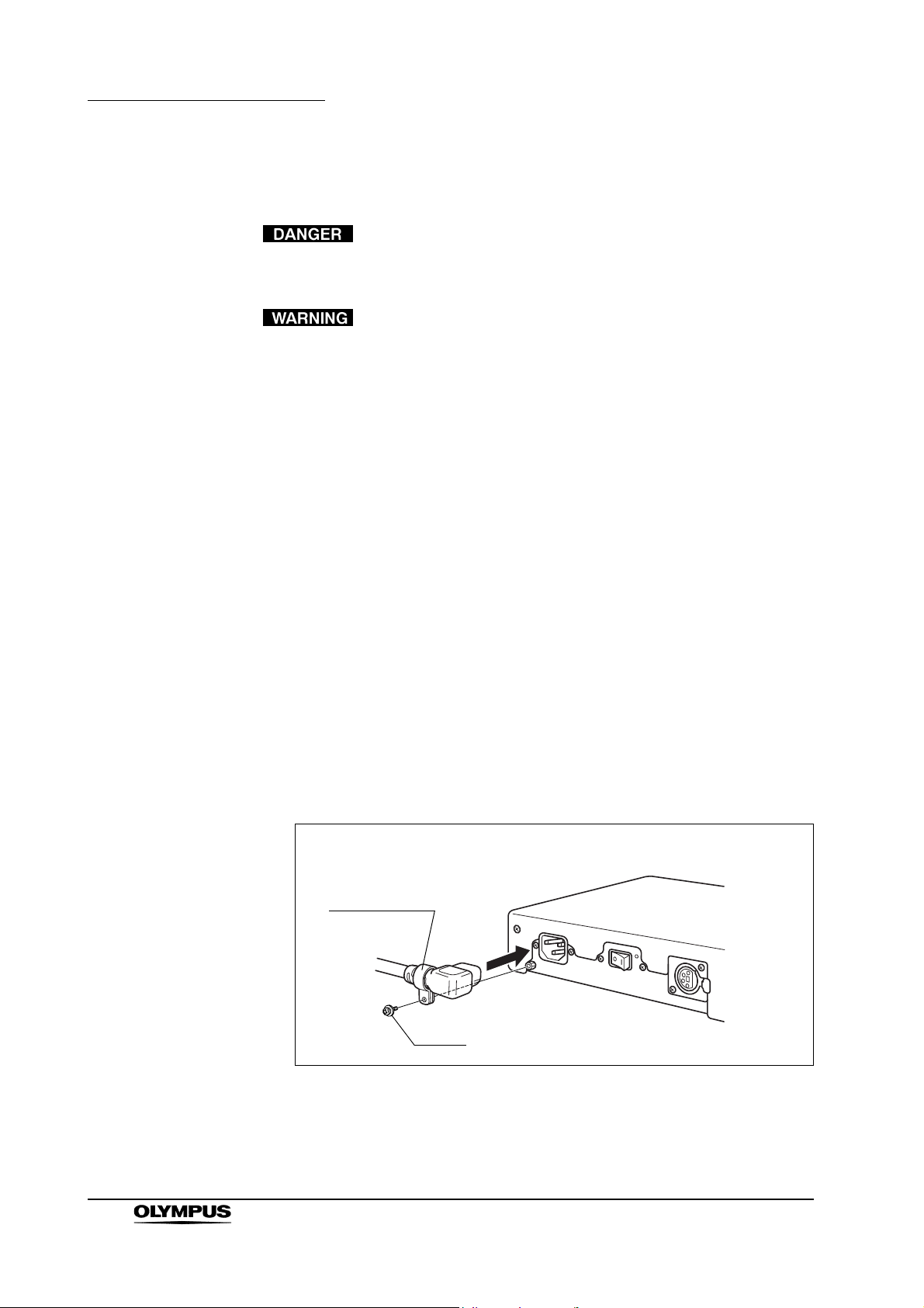
1. Connect the power cord to the AC IN terminal on the AC adapter (see
Figure 3.1).
Use the supplied screw (for securing power cord) and the power cord hook
to secure the power cord to the AC adapter.
Power cord
hook
24
Screw
Figure 3.1
High definition LCD monitor OEV261H
Page 29

Chapter 3 Installation and Connection
2. Slide the supplied DC cord into the DC OUT terminal on the AC adapter until
it is locked in place (see Figure 3.2).
Figure 3.2
3. Slide the DC cord into the DC IN terminal on the monitor until it locks in
place (see Figure 3.3).
Figure 3.3
4. Connect the power cord to the wall mains outlet.
The power cord supplied with this should be connected to the wall mains
outlet or mobile workstation.
High definition LCD monitor OEV261H
25
Page 30

Chapter 4 Inspection and Setup Before Use
Chapter 4 Inspection and Setup Before
Use
Before using the monitor, be sure to inspect and set it up as
described in this chapter. Also inspect the ancillary
equipment to be used in combination with this monitor as
described in the instruction manuals for the equipment. If any
irregularity is suspected with the monitor, do not use it and
take remedial actions as described in Chapter 10,
“Troubleshooting”. If this cannot restore the normal
operation, contact Olympus. Using the LCD monitor
(OEV261H) while an irregularity is suspected does not only
result in malfunction but may also cause an electric shock,
injury and/or fire.
Inspect the monitor and ancillary equipment according to the purpose of use by
referring to the “System chart” in Appendix. For the inspection, observe the
following sections and also refer to the instruction manuals for the ancillary
equipment.
4.1 Power supply
Inspecting the power supply
Confirm that the monitor can be turned On as described on Section 2.2, “Front
panel” on page 15 and Section 2.4, “AC adapter” on page 19. The POWER LED
should light up in green.
When the monitor does not power On, check the equipment as follows;
• Confirm that the power cord and DC cord are connected as described in
the instructions Section 3.3, “Connection to an AC mains power supply”
on page 24.
26
High definition LCD monitor OEV261H
Page 31

Chapter 4 Inspection and Setup Before Use
4.2 Inspection of the displayed image
Before using high-frequency electrosurgical equipment, be
sure to install and connect the equipment according to its
instruction manual and make sure that the noise does not
affect the observation and surgical procedures. If
high-frequency electrosurgical equipment is used without
such confirmation, patient injury may result.
1. Connect the required ancillary equipment as described in Chapter 3,
“Installation and Connection”, turn all the ancillary equipment On, and
confirm that the monitor displays an image.
2. Observe the palm of a hand, for example, with the endoscope and confirm
that the endoscopic image is normal.
3. Confirm that there are no cracks in the LCD panel.
High definition LCD monitor OEV261H
27
Page 32

Chapter 5 Screen Menu and Operation of Front Panel
Chapter 5 Screen Menu and Operation
of Front Panel
5.1 PRESET button
Previously recorded Olympus settings or user original settings can be loaded,
and user original settings can be saved.
Load of recorded settings
Use to select (LOAD tab) in the tabs and press to open the FILE
LOAD submenu to load the recorded settings.
28
Use to move the cursor up, down, left, and right. Pressing when
the cursor is at the top changes the cursor back to the tab selection.
∗ z: Displays confirmed preset.
∗ White characters: Displays selected preset value.
High definition LCD monitor OEV261H
Page 33

Chapter 5 Screen Menu and Operation of Front Panel
Operation
1. Press [Enter] and a confirmation menu appears on the monitor.
2. Use to move the cursor.
Select [YES] and press [ENTER] to load the selected settings; the FILE
LOAD submenu reappears.
Select [NO] and press [ENTER] or [PRESET] to cancel; the FILE LOAD
submenu reappears.
∗ To exit the PRESET menu, either press the PRESET button again or wait for
10 seconds.
∗ When the control lock is engaged, the key mark appears on the monitor and
operation is disabled.
PRESET settings
Device connected to the monitor Setting value
Video system center CV-180 PRESET F
Video system center CV-260SL, CV-260 (A), CV-260 (B),
CV-165, CV-160, CV-145, Endoscopic ultrasound center
EU-ME1, EU-M2000/M60, EU-C2000/C60, or EU-M30S
Video system center OTV-S7Pro, OTV-S7V
Camera control unit OTV-SP1C∗1, OTV-SP1C-G
Video system OTV-SI∗1, OTV-SC
It does not use PRESET A – E, I, J
∗1
∗1
∗1
∗1: Need to change the setting of input terminal.
PRESET G
PRESET H
High definition LCD monitor OEV261H
29
Page 34

Chapter 5 Screen Menu and Operation of Front Panel
PRESET A PRESET B PRESET C
INPUT CONFIG
Video/Y/C AUTO AUTO AUTO
RGB/YP
BPR
SELECT SYNC AUTO AUTO AUTO
COMP.
RGB SQUARE SQUARE SQUARE
HD15 SQUARE SQUARE SQUARE
DVI-D1 DVI-COMP. DVI-COMP. DVI-COMP.
DVI-D2 DVI-VIDEO DVI-VIDEO DVI-VIDEO
VIDEO CONFIG
BACKLIGHT 50 50 50
COLOR TEMP. D93 D93 D65
COLOR MODE of each
input terminal
VIDEO 1-A 1-B 2-A
Y/C 1-A 1-B 2-A
RGB/YP
BPR
HD15 6-A 6-A 6-A
SDI1 1-A 1-B 2-A
SDI2 1-A 1-B 2-A
DVI-D1 6-A 6-A 6-A
DVI-D2 1-A 1-B 2-A
SYSTEM CONFIG
MENU POSITION
STATUS DISPLAY 3SEC OFF 3SEC OFF 3SEC OFF
POWER ON SETUP LAST LAST LAST
POWER SAVE MODE OFF OFF OFF
LANGUAGE
LOGO ON ON ON
FUNCTION
FUNCTION1 PORT A GAMMA SELECT PORT A GAMMA SELECT PORT A GAMMA SELECT
FUNCTION2 PORT B GAMMA SELECT PORT B GAMMA SELECT PORT B GAMMA SELECT
FUNCTION DISPLAY ON2 ON2 ON2
WINDOW CONFIG
PIP
PORT A DISPLAY
MODE
PORT B DISPLAY
MODE
DISPLAY POSITION
POP
PORT A DISPLAY
MODE
PORT B DISPLAY
MODE
DISPLAY POSITION MODE1 MODE1 MODE1
DISPLAY PATTERN PORT A PORT A PORT A
SQUARE PATTERN MODE1 MODE1 MODE1
REMOTE CONFIG
GPI CONTROL ENABLE ENABLE DISABLE
GPI1 PORT A INPUT VIDEO UNDEF PORT A INPUT SDI1
GPI2 PORT A INPUT Y/C
GPI3
GPI4 UNDEF PORT A INPUT Y/C PORT A INPUT Y/C
GPI5 UNDEF UNDEF UNDEF
GPI6 UNDEF UNDEF UNDEF
GPI7 UNDEF UNDEF UNDEF
GPI8 UNDEF UNDEF UNDEF
CONTROL
CONTROL LOCK ON ON ON
FRONT LOCK MENU MENU MENU
INPUT
PORT A RGB RGB SDI1
PORT B Y/C Y/C RGB
RGB-VIDEO RGB-VIDEO RGB-VIDEO
1-A 1-B 2-A
4:3 4:3 5:4
NORMAL NORMAL 43
4:3 4:3 5:4
NORMAL NORMAL 4:3
PORT A INPUT RGB/YP
BPR
PORT A INPUT RGB/YP
BPR
PORT A INPUT VIDEO PORT A INPUT VIDEO
PORT A INPUT RGB/YPBP
R
30
High definition LCD monitor OEV261H
Page 35

Chapter 5 Screen Menu and Operation of Front Panel
PRESET D PRESET E PRESET F
INPUT CONFIG
Video/Y/C AUTO AUTO AUTO
RGB/YP
BPR
SELECT SYNC AUTO AUTO AUTO
COMP.
RGB SQUARE SQUARE SQUARE
HD15 SQUARE SQUARE SQUARE
DVI-D1 DVI-COMP. DVI-COMP. DVI-COMP.
DVI-D2 DVI-VIDEO DVI-VIDEO DVI-VIDEO
VIDEO CONFIG
BACKLIGHT 50 50 50
COLOR TEMP. D93 D65 D65
COLOR MODE of each
input terminal
VIDEO 8-A 8-A 2-A
Y/C 8-A 8-A 2-A
RGB/YP
BPR
HD15 6-A 6-A 6-A
SDI1 8-A 8-A 2-A
SDI2 8-A 8-A 2-A
DVI-D1 6-A 6-A 6-A
DVI-D2 8-A 8-A 2-A
SYSTEM CONFIG
MENU POSITION
STATUS DISPLAY 3SEC OFF 3SEC OFF 3SEC OFF
POWER ON SETUP LAST LAST LAST
POWER SAVE MODE OFF OFF OFF
LANGUAGE ENGLISH
LOGO ON ON ON
FUNCTION
FUNCTION1 PORT A GAMMA SELECT PORT A GAMMA SELECT PORT A GAMMA SELECT
FUNCTION2 PORT B GAMMA SELECT PORT B GAMMA SELECT PORT B GAMMA SELECT
FUNCTION DISPLAY ON2 ON2 ON2
WINDOW CONFIG
PIP
PORT A DISPLAY
MODE
PORT B DISPLAY
MODE
DISPLAY POSITION
POP
PORT A DISPLAY
MODE
PORT B DISPLAY
MODE
DISPLAY POSITION MODE1 MODE1 MODE1
DISPLAY PATTERN PORT A PORT A PORT A
SQUARE PATTERN MODE1 MODE1 MODE1
REMOTE CONFIG
GPI CONTROL ENABLE DISABLE ENABLE
GPI1 PORT A INPUT VIDEO PORT A INPUT SDI1 PORT A INPUT SDI1
GPI2 PORT A INPUT Y/C
GPI3
GPI4 UNDEF PORT A INPUT Y/C PORT A INPUT Y/C
GPI5 UNDEF UNDEF UNDEF
GPI6 UNDEF UNDEF UNDEF
GPI7 UNDEF UNDEF UNDEF
GPI8 UNDEF UNDEF UNDEF
CONTROL
CONTROL LOCK ON ON ON
FRONT LOCK MENU MENU MENU
INPUT
PORT A SDI1 SDI1 SDI1
PORT B RGB SDI2 DVI-D1
RGB-VIDEO RGB-VIDEO RGB-VIDEO
8-A 8-A 2-A
NORMAL 5:4 5:4
4:3 SQUARE 5:4
NORMAL 5:4 5:4
4:3 SQUARE 5:4
PORT A INPUT RGB/YP
BPR
PORT A INPUT RGB/YP
BPR
PORT A INPUT VIDEO PORT A INPUT VIDEO
PORT A INPUT RGB/YPBP
R
High definition LCD monitor OEV261H
31
Page 36

Chapter 5 Screen Menu and Operation of Front Panel
PRESET G PRESET H PRESET I
INPUT CONFIG
Video/Y/C AUTO AUTO AUTO
RGB/YP
BPR
SELECT SYNC AUTO AUTO AUTO
COMP.
RGB SQUARE SQUARE SQUARE
HD15 SQUARE SQUARE SQUARE
DVI-D1 DVI-COMP. DVI-COMP. DVI-COMP.
DVI-D2 DVI-VIDEO DVI-VIDEO DVI-VIDEO
VIDEO CONFIG
BACKLIGHT 50 50 50
COLOR TEMP. D65 D65 D65
COLOR MODE of each
input terminal
VIDEO 1-A 2-A 8-A
Y/C 1-A 2-A 8-A
RGB/YP
BPR
HD15 6-A 6-A 6-A
SDI1 1-A 2-A 8-A
SDI2 1-A 2-A 8-A
DVI-D1 6-A 6-A 6-A
DVI-D2 1-A 2-A 8-A
SYSTEM CONFIG
MENU POSITION
STATUS DISPLAY 3SEC OFF 3SEC OFF 3SEC OFF
POWER ON SETUP LAST LAST LAST
POWER SAVE MODE OFF OFF OFF
LANGUAGE ENGLISH ENGLISH ENGLISH
LOGO ON ON ON
FUNCTION
FUNCTION1 PORT A GAMMA SELECT PORT A GAMMA SELECT PORT A GAMMA SELECT
FUNCTION2 PORT B GAMMA SELECT PORT B GAMMA SELECT PORT B GAMMA SELECT
FUNCTION DISPLAY ON2 ON2 ON2
WINDOW CONFIG
PIP
PORT A DISPLAY
MODE
PORT B DISPLAY
MODE
DISPLAY POSITION
POP
PORT A DISPLAY
MODE
PORT B DISPLAY
MODE
DISPLAY POSITION MODE1 MODE1 MODE1
DISPLAY PATTERN PORT A PORT A PORT A
SQUARE PATTERN MODE1 MODE1 MODE1
REMOTE CONFIG
GPI CONTROL ENABLE DISABLE DISABLE
GPI1 PORT A INPUT VIDEO PORT A INPUT SDI1 PORT A INPUT VIDEO
GPI2 PORT A INPUT Y/C
GPI3
GPI4 UNDEF PORT A INPUT Y/C UNDEF
GPI5 UNDEF UNDEF UNDEF
GPI6 UNDEF UNDEF UNDEF
GPI7 UNDEF UNDEF UNDEF
GPI8 UNDEF UNDEF UNDEF
CONTROL
CONTROL LOCK ON ON ON
FRONT LOCK MENU MENU MENU
INPUT
PORT A RGB SDI1 SDI1
PORT B DVI-D1 SDI2 DVI-D1
RGB-VIDEO RGB-VIDEO RGB-VIDEO
1-A 2-A 8-A
4:3 5:4 NORMAL
5:4 5:4 5:4
4:3 5:4 NORMAL
5:4 5:4 5:4
PORT A INPUT RGB/YP
BPR
PORT A INPUT RGB/YP
PORT A INPUT VIDEO
BPR
PORT A INPUT Y/C
PORT A INPUT RGB/YP
BPR
32
High definition LCD monitor OEV261H
Page 37

PRESET J
INPUT CONFIG
Video/Y/C AUTO
RGB/YP
COMP.
DVI-D1 DVI-COMP.
DVI-D2 DVI-VIDEO
VIDEO CONFIG
BACKLIGHT 50
COLOR TEMP. D65
COLOR MODE of each
input terminal
SYSTEM CONFIG
MENU POSITION
STATUS DISPLAY 3SEC OFF
POWER ON SETUP LAST
POWER SAVE MODE OFF
LANGUAGE ENGLISH
LOGO ON
FUNCTION
FUNCTION1 PORT A GAMMA SELECT
FUNCTION2 PORT B GAMMA SELECT
FUNCTION DISPLAY ON2
WINDOW CONFIG
PIP
POP
REMOTE CONFIG
GPI CONTROL DISABLE
GPI1 PORT A INPUT SDI1
GPI2
GPI3
GPI4 PORT A INPUT Y/C
GPI5 UNDEF
GPI6 UNDEF
GPI7 UNDEF
GPI8 UNDEF
CONTROL
CONTROL LOCK ON
FRONT LOCK MENU
INPUT
PORT A SDI1
PORT B SDI2
BPR
SELECT SYNC AUTO
RGB SQUARE
HD15 SQUARE
VIDEO 8-A
Y/C 8-A
RGB/YP
HD15 6-A
SDI1 8-A
SDI2 8-A
DVI-D1 6-A
DVI-D2 8-A
PORT A DISPLAY
MODE
PORT B DISPLAY
MODE
DISPLAY POSITION
PORT A DISPLAY
MODE
PORT B DISPLAY
MODE
DISPLAY POSITION MODE1
DISPLAY PATTERN PORT A
SQUARE PATTERN MODE1
BPR
RGB-VIDEO
8-A
5:4
SQUARE
5:4
SQUARE
PORT A INPUT RGB/YP
PORT A INPUT VIDEO
Chapter 5 Screen Menu and Operation of Front Panel
BPR
High definition LCD monitor OEV261H
33
Page 38

Chapter 5 Screen Menu and Operation of Front Panel
Save the user original settings
Use to select (SAVE tab) in the tabs and press to open the FILE
SAVE submenu to save the user original settings.
Use to move the cursor up, down, left, and right. Pressing when
the cursor is at the top changes the cursor back to the tab selection.
∗ z: Displays confirmed preset.
∗ White characters: Displays selected preset value.
Operation
1. Press [Enter] and a confirmation menu appears on the monitor.
2. Use to move the cursor.
Select [YES] and press [ENTER] to save the user original settings; the FILE
SAVE submenu reappears.
Select [NO] and press [ENTER] or [PRESET] to cancel; the FILE SAVE
submenu reappears.
34
High definition LCD monitor OEV261H
Page 39

Chapter 5 Screen Menu and Operation of Front Panel
∗ To exit the PRESET menu, either press the PRESET button again or wait for
10 seconds.
∗ When the control lock is engaged, the key mark appears on the monitor and
operation is disabled.
5.2 INPUT button
The input terminal for PORT A and PORT B signals can be selected.
Use to move the cursor up, down, left, and right.
High definition LCD monitor OEV261H
35
Page 40

Chapter 5 Screen Menu and Operation of Front Panel
Operation
1. Press [INPUT] to select the input terminal, and INPUT menu disappears.
2. Press [MENU] to adjust the value of selected input terminal. Refer to
Section 6.5, “VIDEO INPUT” on page 51.
∗ z: Displays confirmed input signal.
∗ White characters: Displays selected preset value.
∗ As soon as the INPUT button is pressed, the indication for the PORT input
terminal whose video is currently displayed appears in white in single screen
display. In dual screen display, the indication for the PORT A input terminal
appears in white.
∗
Using to switch PORT will display selected input terminal in white.
∗ To exit the INPUT menu, either press the INPUT button again or wait for
10 seconds.
∗ PORT operations are disabled when the input terminal is controlled by GPI.
PORTs controlled by GPI are displayed in gray.
∗ When the control lock is engaged, the key mark appears and operation is
disabled.
5.3 MENU button
Various settings of the monitor can be adjusted.
36
Use to select a tab. Select the tab you want to set, and then press to
move the cursor to the first item in the submenu to set a submenu. Refer to
Chapter 6, “Submenu Operations”.
∗ To exit the MENU, either press the MENU button again or wait for
120 seconds.
High definition LCD monitor OEV261H
Page 41

Chapter 5 Screen Menu and Operation of Front Panel
∗ For a list of the items in the MENU, refer to the following.
High definition LCD monitor OEV261H
37
Page 42

Chapter 5 Screen Menu and Operation of Front Panel
5.4 PIP button
Switches from the normal screen, dual PIP screen and PIP mode.
Example showing operation each time the PIP button is
pressed
The display changes in the following order when the PIP button is pressed.
(1) → (2) → (3) → (4) → (5) → (6 ) → (1) → .....
(1) shows only the PORT A image.
(2) and (3) shows an enlarged view of the PORT A image.
(4) and (5) shows an enlarged view of the PORT B image.
(6) shows only the PORT B image.
∗ The status display can be set to “CONTINUE,” “3SEC OFF,” or “OFF” in PIP
screen mode.
∗ PIP button operation is disabled when PRESET, INPUT, and MENU screens
are displayed.
∗ If the monitor is shut down during PIP operation and the POWER ON SETUP
setting is set to LAST, the status prevailing at shutdown is stored in memory.
∗ PIP button operations are disabled when the FLIP button is used.
∗ When the control lock is engaged, the key mark appears and operation is
disabled.
∗
An example showing the PIP DISPLAY POSITION at (the top right of
the screen).
38
High definition LCD monitor OEV261H
Page 43

5.5 POP button
Switches from the normal display to the dual POP screen and to POP mode.
Example showing operation when the POP button is pressed
The display changes in the following order each time the POP button is pressed.
(1) → (2) → (3) → (4) → (5) → (1) → .....
Chapter 5 Screen Menu and Operation of Front Panel
(1) shows only the PORT A image.
(2) shows an enlarged view of the PORT A image.
(3) shows the PORT A and B images at equal size.
(4) shows an enlarged view of the PORT B image.
(5) shows only the PORT B image.
∗ The status display can be set to “CONTINUE,” “3SEC OFF,” or “OFF” in POP
screen mode.
∗ POP button operation is disabled when PRESET, INPUT, and MENU screens
are displayed.
∗ If the monitor is shut down during POP operation and the POWER ON
SETUP setting is set to LAST, the status prevailing at shutdown is stored in
memory.
∗ POP button operations are disabled when the FLIP button is used.
∗ When the control lock is engaged, the key mark appears and operation is
disabled.
∗ An example of POP DISPLAY POSITION in MODE1.
High definition LCD monitor OEV261H
39
Page 44

Chapter 5 Screen Menu and Operation of Front Panel
5.6 SCAN button
The single screen display and the large screen in PIP mode can be magnified.
Refer to “SCAN SIZE screen mode” on page 61.
∗ The display changes in the following;
SD image: OFF → MODE1 → MODE2 → OFF...
HD image: OFF → MODE3 → MODE4 → MODE5 → MODE6 → MODE7
→ OFF...
5.7 FUNCTION buttons (F1, F2/ENTER)
Items assigned to the FUNCTION buttons appear when these buttons are
pressed. To confirm items assigned to the FUNCTION buttons, press these
buttons again. Refer to Section 6.7, “FUNCTION” on page 64.
40
∗ The screen closes automatically two seconds after the last FUNCTION
operation.
∗ This screen always appears in the same location.
∗ When the control lock is engaged, the key mark appears on the monitor and
operation is disabled.
∗1: Function Name: Indicates the name of a function. Select display or hide.
∗2: Function Status: Shows the status of the selected function.
High definition LCD monitor OEV261H
Page 45

5.8 Status display
This screen appears when the power is turned On, input terminals are changed,
formats are switched, and when the MENU, FUNCTION, PRESET, and INPUT
displays are closed.
Single screen display
The first line displays the name of the input terminal of currently displayed video.
The second line displays signal format. The third line displays FLIP and control
lock status.
Chapter 5 Screen Menu and Operation of Front Panel
Dual screen display
• The first line displays the names of the input terminals for both PORT A
and B. The second line displays signal format. The third line displays
PIP, POP and control lock status.
High definition LCD monitor OEV261H
41
Page 46

Chapter 5 Screen Menu and Operation of Front Panel
• When the right and left images trade places, the input PORT and signal
display follow suit.
• Status display of an enlarged view appears at top left of the
screen during PIP operation.
• Select one of the following display periods.
− CONTINUE
− 3 SEC OFF
− OFF
However, FLIP status is always displayed.
:
Upside-down image
:
Reversed image
Table 5.1 shows the signal format and display on the monitor.
• “UNSUPPOTRT SIGNAL” appears if an unsupported signal
is input. It may also indicate that the format selected in the
“INPUT CONFIG” menu does not match the input signal.
• “NO SIGNAL” appears if no signal is input.
• “UNSUPPORT SIGNAL” and “NO SIGNAL” may not be
properly displayed.
42
High definition LCD monitor OEV261H
Page 47

Chapter 5 Screen Menu and Operation of Front Panel
Input terminal
Display
Signal format
NTSC NTSC {
PAL PAL {
480/59.94i 480/59.94i {{{
480/59.94p 480/59.94p {{ {
576/50i 576/50i {{{
576/50p 576/50p {{ {
720/59.94p 720/59.94p {{{ {
720/60p 720/60p {{{ {
1080/50i 1080/50i {{{ {
1080/50p 1080/50p {{
1080/59.94i 1080/59.94i {{{ {
1080/60i 1080/60i {{{ {
1080/59.94p 1080/59.94p {{
1080/60p 1080/60p {{
VGA: 640 × 480 (60 Hz) 640 × 480 (60 Hz) {{
SVGA: 800 × 600 (60 Hz) 800 × 600 (60 Hz) {{
XGA: 1024 × 768 (60 Hz) 1024 × 768 (60 Hz) {{
WXGA: 1280 × 768 (60 Hz) 1280 × 768 (60 Hz) {{
SXGA: 1280 × 1024 (60 Hz) 1280 × 1024 (60 Hz) {{
UXGA: 1600 × 1200 (60 Hz) 1600 × 1200 (60 Hz) {{
WUXGA: 1920 × 1200
(60 Hz)
1920 × 1200 (60 Hz)
VIDEO/
Y/C
SDI1/SDI
2
YP
BPR
RGB
RGB-CO
MP./HD15
{
DVI-D1/D
VI-D2
(VIDEO
signal)
∗1
DVI-D1/D
VI-D2 (PC
signal)
{
Table 5.1
When signals other than the above mentioned are input, “UNSUPPORT
SIGNAL” is displayed.
∗1: Only compatible with VESA (Video Electronics Standards Association)
Reduced Blanking (Clock: 154 MHz, Hsync: positive logic, Vsync: negative
logic).
High definition LCD monitor OEV261H
43
Page 48

Chapter 6 Submenu Operations
Chapter 6 Submenu Operations
6.1 INPUT CONFIG
Use to select (INPUT tab) in the tabs and press to open the INPUT
CONFIG submenu to make the desired settings.
Use to move the cursor up and down. Pressing when the cursor is at
the top changes the cursor back to the tab selection. Pressing when the
cursor is at the bottom moves the cursor to the top.
Subsequent operations differ, depending on the selected submenu item.
Selecting an item for which a value has been set
1.
Press [ENTER] and the set submenu setting turns green.
2. Use to change the set value.
Use [ENTER] to confirm the change; the submenu selection screen
reappears.
Use [MENU] to cancel the change; the submenu selection screen
reappears.
44
High definition LCD monitor OEV261H
Page 49

Chapter 6 Submenu Operations
Selecting an item where appears in the value field
A list of additional submenus appears.
Submenu Description
VIDEO/ Y/C Selects the format of signals input to the VIDEO, Y and C input terminals.
• AUTO Automatically selects NTSC or PAL.
•NTSC Selects NTSC.
• PAL Selects PAL.
RGB/YP
SELECT SYNC Selects the synchronizing signal when using YP
BPR
Selects RGB or YPBPR input.
•YP
BPR
• RGB-VIDEO Selects the video RGB signal.
• RGB-COMP. Selects the COMP. RGB signal.
• AUTO Automatically detects the synchronizing signal (G-ON has priority)
Selects the YPBPR signal.
and RGB-VIDEO input.
BPR
• INT Selects the synchronizing signal superimposed on the Y signal for YP
and the synchronizing signal superimposed on the G signal for RGB-VIDEO input.
• EXT External synchronization
When GPI of EXT is enabled and the item is assigned, the item appears gray to indicate that
selection is disabled and the set GPI value appears.
COMP. Sets up a connection to a computer (COMP.).
∗ Enabled only for RGB-COMP. and HD15 inputs.
Switches between values set for each input terminal.
∗ Enabled only during one screen display in PC input.
Select and press [ENTER] to open the COMP. submenu (page 46).
RGB Switches between the WIDE and normal screen for RGB-COMP. signal of RGB-input-terminal.
• WIDE Shows the WIDE screen.
• SQUARE Shows the normal screen.
HD15 Switches between the WIDE and normal screen for signal of the HD15-input-terminal.
• WIDE Shows the WIDE screen.
• SQUARE Shows the normal screen.
DVI-D1 Selects the format of signals input to the DVI-D1 input terminal.
• DVI-VIDEO Selects component input.
• DVI-COMP. Selects COMP. input.
BPR
input
DVI-D2 Selects the format of signals input to the DVI-D2 input terminal.
• DVI-VIDEO Selects component input.
• DVI-COMP. Selects COMP. input.
Fiber adapter is connected to this DVI-D2 terminal.
High definition LCD monitor OEV261H
45
Page 50

Chapter 6 Submenu Operations
6.2 COMP.
Selecting COMP. in INPUT CONFIG submenu opens the following menu.
∗ This menu is enabled only in single screen display during COMP. input.
Use to move the cursor up and down. Pressing when the cursor is at
the top changes the cursor back to the tab selection. Pressing when the
cursor is at the bottom moves the cursor to the top.
Operation
1.
Use to select a set item and press or [ENTER].
2. Use to change the set value.
Use [ENTER] to confirm the change; the submenu selection screen
reappears.
Use [MENU] to cancel the change; the submenu selection screen
reappears.
∗ These settings are used for each RGB-COMP. and HD15 input terminal.
46
High definition LCD monitor OEV261H
Page 51

Submenu Description
∗1
AUTOSETUP
H POSITION Adjusts the image display position in the horizontal direction.
V POSITION Adjusts the image display position in the vertical direction.
PHASE Adjusts the clock phase in 1/32 clock-period increments.
CLOCK
∗3
Performs auto screen setup when RGB-COMP. or HD15 is selected.
Select AUTOSETUP and press [ENTER] to open a confirmation screen.
Select YES and press [ENTER] to start AUTOSETUP.
Adjustments can be made to each format compatible with COMP. input.
• 0 – 30 – 60
Adjustments can be made to each format compatible with COMP. input.
• 0 – 30 – 60
Adjustments can be made to each format compatible with COMP. input.
• 0 – 16 – 31
Adjusts the sampling clock in dot units.
Adjustments can be made to each format compatible with COMP. input.
• 700 – 2200
Default value: Depends on signal format
Chapter 6 Submenu Operations
∗2
∗2
∗2
∗2
RESET Returns the H/V POSITION, PHASE and CLOCK to the factory default settings for currently
displayed COMP. input format.
Select RESET and press [ENTER] to open a confirmation screen.
Select YES and press [ENTER] to return currently displayed format adjustments to their default
values.
∗1: [AUTOSETUP] Use this function when the entire screen area is available for display.
“EXECUTING” is displayed during “AUTOSETUP” and “COMPLETE” appears when setup
completes. “INCOMPLETE” is displayed if setup could not be completed.
AUTOSETUP may not provide adequate adjustment in all cases. Use H POSITION, V
POSITION, PHASE and CLOCK to adjust.
∗2: Adjustment is available for compatible input formats, but settings cannot be loaded from and
saved to user files.
∗3: “CLOCK” factory default
Format CLOCK
640
×
480 (60 Hz) 800
×
600 (60 Hz) 1050
800
×
1024
1280
1280
1600
1920
768 (60 Hz) 1344
×
768 (60 Hz) 1680
×
1024 (60 Hz) 1688
×
1200 (60 Hz) 2160
×
1200 (60 Hz) 2080
High definition LCD monitor OEV261H
47
Page 52

Chapter 6 Submenu Operations
6.3 VIDEO CONFIG
Use to select (VIDEO tab) in the tabs and press to open the
VIDEO CONFIG submenu to make the desired settings.
The menu items of BACKLIGHT and COLOR TEMP. are settings shared by all
video signal input terminals. The remaining menu items are names of video input
terminals. Selecting a terminal opens the VIDEO INPUT submenu for that video
input terminal.
Submenu Description
BACKLIGHT Adjusts the brightness of the backlight.
• 0 – 50 (default value: 50)
COLOR TEMP. Sets the color temperature.
• USER∗∗∗1......................................
• D93 ................................................ equivalent to a color temperature of 9300 K
• D65 (default value)......................... equivalent to a color temperature of 6500 K
• VAR1: Opens submenu for adjusting WB adjustment mode 1
• VAR2: Opens submenu for adjusting WB adjustment mode 2
• VAR3: Opens submenu for adjusting WB adjustment mode 3
VIDEO
Y/C
RGB/YP
HD15
SDI1
SDI2
DVI-D1
DVI-D2
BPR
Set the image quality from the each signal input terminal.
See page 51 for a description of a setup procedure.
Adjustable settings 0 – 63 (equivalent to a color
temperature range of 3000 – 9300 K)
48
∗1: To use USER ∗∗ adjustable settings 0 – 63, select USER and press ENTER once so that
USER changes to light blue. Then use and to change ∗∗.
Press ENTER once more to change USER back to white and confirm the setting.
High definition LCD monitor OEV261H
Page 53

6.4 WHITE BALANCE
Selecting VAR1 – 3 under COLOR TEMP. in the VIDEO CONFIG submenu and
pressing ENTER opens the WHITE BALANCE submenu.
Chapter 6 Submenu Operations
Use to move the cursor up and down. Pressing when the cursor is at
the top changes the cursor back to the tab selection. Pressing when the
cursor is at the bottom moves the cursor to the top.
Operation
1.
Use to select a set item and press or [ENTER].
2. Use to change the set value.
Use [ENTER] to confirm the change; the submenu selection screen
reappears.
Use [MENU] to cancel the change; the submenu selection screen
reappears.
High definition LCD monitor OEV261H
49
Page 54

Chapter 6 Submenu Operations
Submenu Description
COLOR TEMP. Sets the color temperature.
The default color temperature values selected here is reflected to each GAIN and BIAS value.
• USER** .......................................... Adjustable settings 0 – 63 (equivalent to a color
temperature range of 3000 – 9300 K) (default value: 63)
• D93 ................................................ equivalent to a color temperature of 9300 K
• D65 (default value)......................... equivalent to a color temperature of 6500 K
GAIN RED Adjusts the GAIN for the red component.
The default value is adjusted using D65 and is unique for each set.
• 0 – 1023
GAIN GREEN Adjusts the GAIN for the green component.
The default value is adjusted using D65 and is unique for each set.
• 0 – 1023
GAIN BLUE Adjusts the GAIN for the blue component.
The default value is adjusted using D65 and is unique for each set.
• 0 – 1023
BIAS RED Adjusts the BIAS for the red component.
• –512 to 0 to 511 (default value: 0)
BIAS GREEN Adjusts the BIAS for the green component.
• –512 to 0 to 511 (default value: 0)
BIAS BLUE Adjusts the BIAS for the blue component.
• –512 to 0 to 511 (default value: 0)
RESET Resets the COLOR TEMP. adjustments to their factory default settings.
Each COLOR TEMP. selected using GAIN and BIAS was restored to its factory default.
50
High definition LCD monitor OEV261H
Page 55

6.5 VIDEO INPUT
Selecting the name of a video input terminal in the VIDEO CONFIG submenu
opens the INPUT submenu.
Chapter 6 Submenu Operations
Use to move the cursor up and down. Pressing when the cursor is at
the top changes the cursor back to the tab selection. Pressing when the
cursor is at the bottom moves the cursor to the top.
Operation
1.
Use to select a set item and press or [ENTER].
2. Use to change the set value.
Use [ENTER] to confirm the change; the submenu selection screen
reappears.
Use [MENU] to cancel the change; the submenu selection screen
reappears.
∗ This menu item is enabled on both screens when video from the same
VIDEO, Y/C, RGB/YP
in split-screen display.
Submenu Description
COLOR MODE Sets (1 – 10) MODE and ITEM (A – J) in COLOR MODE.
See page 54 for a description of a setup procedure.
RED Adjusts RED GAIN
0 – 60 (default value: 30)
, SDI1, SDI2, DVI-D1 and DVI-D2 terminal is used
BPR
GREEN Adjusts GREEN GAIN
0 – 60 (default value: 30)
BLUE Adjusts BLUE GAIN
0 – 60 (default value: 30)
High definition LCD monitor OEV261H
51
Page 56

Chapter 6 Submenu Operations
Submenu Description
GAMMA
SELECT
SCAN SIZE HD SDMagnifies the single screen display and the large screen in PIP mode.
Sets the incline of the gamma curve.
• ENDOSCOPE (default value)
•1.8
•1.95
•2.0
•2.2
•2.4
•2.6
•PACS
When COMP. input is selected, the set value is — (line). This cannot be selected, nor any other
selection can be made.
When GPI is enabled and an item is assigned, the item appears gray to indicate that selection is
disabled and the set GPI value appears.
SCAN SIZE SD
OFF Normal display
MODE1 Magnifies SD signal image to horizontal panel size (1920 pixels)
MODE2 Magnifies SD signal image to vertical panel size (1200 pixels)
SCAN SIZE HD
OFF Normal display
MODE3 Magnifies HD signal image to vertical panel size (1200 pixels)
MODE4 Magnifies special area 1 (1422 × 1064) of an HD signal to horizontal panel size
(1920 pixels).
MODE5 Magnifies special area 1 (1422 × 1064) of an HD signal to vertical panel size
(1200 lines).
MODE6 Magnifies special area 2 (1280 × 1008) of an HD signal to horizontal panel size
(1920 pixels).
MODE7 Magnifies special area 2 (1280 × 1008) of an HD signal to vertical panel size
(1200 lines).
SD Aspect ratio is fixed at 4:3.
SD only input terminals display SD items only (MODE1 and 2).
* HD signal: MODE3 to 7 described above enable only 1080i (60 Hz/59.94 Hz/50 Hz) or 1080p
(60 Hz/59.94 Hz/50 Hz) HD signals, other HD signals are impossible.
target screen target screen
Normal screen PIP screen
See page 61 for a description of a scan size.
52
High definition LCD monitor OEV261H
Page 57

Submenu Description
MONO Enables or disables monochrome display.
When COMP. input is selected, the set value is — (line). This cannot be selected, nor any other
selection can be made.
• OFF (default value) ....................... Color display
• ON ................................................. Monochrome display
PHASE Adjusts phase.
When COMP. input is selected and the MONO function is on, the set value is — (line). This
cannot be selected, nor any other selection can be made.
0 – 60 (default value: 30)
CHROMA Adjusts chroma.
When COMP. input is selected and the MONO function is on, the set value is — (line). This
cannot be selected, nor any other selection can be made.
0 – 60 (default value: 25)
BRIGHT Adjusts brightness.
0 – 60 (default value: 30)
Chapter 6 Submenu Operations
CONTRAST Adjusts contrast.
0 – 60 (default value: 50)
SHARPNESS
MODE
SHARPNESS H Sets horizontal sharpness.
SHARPNESS V Sets vertical sharpness.
Selects the width of outline correction edge.
• HIGH (default value)...................... Thin edge
• LOW .............................................. Wide edge
When COMP. input is selected, the set value is — (line). This cannot be selected, nor any other
selection can be made.
• 0 – 30
When COMP. input is selected, the set value is — (line). This cannot be selected, nor any other
selection can be made.
• 0 – 30
High definition LCD monitor OEV261H
53
Page 58

Chapter 6 Submenu Operations
Setting COLOR MODE
1. Select COLOR MODE in the INPUT submenu screen and press [ENTER].
The screen for selecting COLOR MODE appears.
2. Use to select a COLOR MODE (1 – 10) and press [ENTER].
The ITEM selection screen appears.
54
High definition LCD monitor OEV261H
Page 59

Chapter 6 Submenu Operations
3. Use to select an ITEM (A – J) and press [ENTER].
A screen confirming the selection appears.
4. Unless a mistake was made in any of the screen settings, use to
select [YES] and press [ENTER].
• The settings are now saved and the previous screen reappears.
• To cancel previous settings, select [NO] and press [ENTER]. The
settings are not saved and the previous screen reappears.
High definition LCD monitor OEV261H
55
Page 60

Chapter 6 Submenu Operations
The value of COLOR MODE
COLOR MODE 1
ITEM A B C D E F G H I J
RED 30303030303030303030
GREEN30303030303030303030
BLUE 30 30 30 30 30 30 30 30 30 30
GAMMA
SELECT
SCAN SIZE HD MODE3 MODE3 MODE3 MODE3 MODE3 MODE3 MODE3 MODE3 MODE3 MODE3
SCAN SIZE SD MODE2 MODE2 MODE2 MODE2 MODE2 MODE2 MODE2 MODE2 MODE2 MODE2
MONO OFF OFF OFF OFF OFF OFF OFF OFF OFF OFF
PHASE 30 30 30 30 30 30 30 30 30 30
CHROMA 25 25 25 25 25 25 28 28 22 22
BRIGHT 30 30 30 30 30 30 30 30 30 30
CONTRAST 50 50 50 44 44 44 44 44 50 50
SHARPNESS
MODE
SHARPNESS H 0 7 10 0 7 10 7 10 7 10
SHARPNESS V 0 7 10 0 7 10 7 10 7 10
ENDOSCOPE ENDOSCOPE ENDOSCOPE ENDOSCOPE ENDOSCOPE ENDOSCOPE ENDOSCOPE ENDOSCOPE ENDOSCOPE ENDOSCOPE
HIGH LOW HIGH HIGH LOW HIGH LOW HIGH LOW HIGH
COLOR MODE 2
ITEM A B C D E F G H I J
RED 30303030303030303030
GREEN30303030303030303030
BLUE 30 30 30 30 30 30 30 30 30 30
GAMMA
SELECT
SCAN SIZE HD MODE7 MODE7 MODE7 MODE7 MODE7 MODE7 MODE7 MODE7 MODE7 MODE7
SCAN SIZE SD MODE2 MODE2 MODE2 MODE2 MODE2 MODE2 MODE2 MODE2 MODE2 MODE2
MONO OFF OFF OFF OFF OFF OFF OFF OFF OFF OFF
PHASE 30 30 30 30 30 30 30 30 30 30
CHROMA 25 25 25 25 25 25 28 28 22 22
BRIGHT 30 30 30 30 30 30 30 30 30 30
CONTRAST 50 50 50 44 44 44 44 44 50 50
SHARPNESS
MODE
SHARPNESS H 0 7 10 0 7 10 7 10 7 10
SHARPNESS V 0 7 10 0 7 10 7 10 7 10
ENDOSCOPE ENDOSCOPE ENDOSCOPE ENDOSCOPE ENDOSCOPE ENDOSCOPE ENDOSCOPE ENDOSCOPE ENDOSCOPE ENDOSCOPE
HIGH LOW HIGH HIGH LOW HIGH LOW HIGH LOW HIGH
56
High definition LCD monitor OEV261H
Page 61

Chapter 6 Submenu Operations
COLOR MODE 3
ITEM A B C D E F G H I J
RED 30303030303030303030
GREEN 30 30 30 30 30 30 30 30 30 30
BLUE 30 30 30 30 30 30 30 30 30 30
GAMMA
SELECT
SCAN SIZE HD MODE7 MODE7 MODE7 MODE7 MODE7 MODE7 MODE7 MODE7 MODE7 MODE7
SCAN SIZE SD MODE2 MODE2 MODE2 MODE2 MODE2 MODE2 MODE2 MODE2 MODE2 MODE2
MONO OFFOFFOFFOFFOFFOFFOFFOFFOFFOFF
PHASE 30 30 30 30 30 30 30 30 30 30
CHROMA 25 25 25 25 25 25 28 28 22 22
BRIGHT 30 30 30 30 30 30 30 30 30 30
CONTRAST 50 50 50 44 44 44 44 44 50 50
SHARPNESS
MODE
SHARPNESS H 0 7 10 0 7 10 7 10 7 10
SHARPNESS V 0 7 10 0 7 10 7 10 7 10
1.95 1.95 1.95 1.95 1.95 1.95 1.95 1.95 1.95 1.95
HIGH LOW HIGH HIGH LOW HIGH LOW HIGH LOW HIGH
COLOR MODE 4
ITEM A B C D E F G H I J
RED 30303030303030303030
GREEN 30 30 30 30 30 30 30 30 30 30
BLUE 30 30 30 30 30 30 30 30 30 30
GAMMA
SELECT
SCAN SIZE HD MODE7 MODE7 MODE7 MODE7 MODE7 MODE7 MODE7 MODE7 MODE7 MODE7
SCAN SIZE SD MODE2 MODE2 MODE2 MODE2 MODE2 MODE2 MODE2 MODE2 MODE2 MODE2
MONO OFFOFFOFFOFFOFFOFFOFFOFFOFFOFF
PHASE 30 30 30 30 30 30 30 30 30 30
CHROMA 25 25 25 25 25 25 28 28 22 22
BRIGHT 30 30 30 30 30 30 30 30 30 30
CONTRAST 50 50 50 44 44 44 44 44 50 50
SHARPNESS
MODE
SHARPNESS H 0 7 10 0 7 10 7 10 7 10
SHARPNESS V 0 7 10 0 7 10 7 10 7 10
2.4 2.4 2.4 2.4 2.4 2.4 2.4 2.4 2.4 2.4
HIGH LOW HIGH HIGH LOW HIGH LOW HIGH LOW HIGH
High definition LCD monitor OEV261H
57
Page 62

Chapter 6 Submenu Operations
COLOR MODE 5
ITEM A B C D E F G H I J
RED 30303030303030303030
GREEN30303030303030303030
BLUE 30 30 30 30 30 30 30 30 30 30
GAMMA
SELECT
SCAN SIZE HD MODE6 MODE6 MODE6 MODE6 MODE6 MODE6 MODE6 MODE6 MODE6 MODE6
SCAN SIZE SD MODE2 MODE2 MODE2 MODE2 MODE2 MODE2 MODE2 MODE2 MODE2 MODE2
MONO OFF OFF OFF OFF OFF OFF OFF OFF OFF OFF
PHASE 30 30 30 30 30 30 30 30 30 30
CHROMA 25 25 25 25 25 25 28 28 22 22
BRIGHT 30 30 30 30 30 30 30 30 30 30
CONTRAST 50 50 50 44 44 44 44 44 50 50
SHARPNESS
MODE
SHARPNESS H 0 7 10 0 7 10 7 10 7 10
SHARPNESS V 0 7 10 0 7 10 7 10 7 10
ENDOSCOPE ENDOSCOPE ENDOSCOPE ENDOSCOPE ENDOSCOPE ENDOSCOPE ENDOSCOPE ENDOSCOPE ENDOSCOPE ENDOSCOPE
HIGH LOW HIGH HIGH LOW HIGH LOW HIGH LOW HIGH
COLOR MODE 6
ITEM A B C D E F G H I J
RED 30303030303030303030
GREEN30303030303030303030
BLUE 30 30 30 30 30 30 30 30 30 30
GAMMA
SELECT
SCAN SIZE HD MODE3 MODE3 MODE3 MODE3 MODE3 MODE3 MODE3 MODE3 MODE3 MODE3
SCAN SIZE SD MODE2 MODE2 MODE2 MODE2 MODE2 MODE2 MODE2 MODE2 MODE2 MODE2
MONO OFF OFF OFF OFF OFF OFF OFF OFF OFF OFF
PHASE 30 30 30 30 30 30 30 30 30 30
CHROMA 25 25 25 25 25 25 28 28 22 22
BRIGHT 30 30 30 30 30 30 30 30 30 30
CONTRAST 50 50 50 44 44 44 44 44 50 50
SHARPNESS
MODE
SHARPNESS H 0 7 10 0 7 10 7 10 7 10
SHARPNESS V 0 7 10 0 7 10 7 10 7 10
2.2 2.2 2.2 2.2 2.2 2.2 2.2 2.2 2.2 2.2
HIGH LOW HIGH HIGH LOW HIGH LOW HIGH LOW HIGH
58
High definition LCD monitor OEV261H
Page 63

Chapter 6 Submenu Operations
COLOR MODE 7
ITEM A B C D E F G H I J
RED 30303030303030303030
GREEN 30 30 30 30 30 30 30 30 30 30
BLUE 30 30 30 30 30 30 30 30 30 30
GAMMA
SELECT
SCAN SIZE HD MODE7 MODE7 MODE7 MODE7 MODE7 MODE7 MODE7 MODE7 MODE7 MODE7
SCAN SIZE SD MODE2 MODE2 MODE2 MODE2 MODE2 MODE2 MODE2 MODE2 MODE2 MODE2
MONO OFFOFFOFFOFFOFFOFFOFFOFFOFFOFF
PHASE 30 30 30 30 30 30 30 30 30 30
CHROMA 25 25 25 25 25 25 28 28 22 22
BRIGHT 30 30 30 30 30 30 30 30 30 30
CONTRAST 50 50 50 44 44 44 44 44 50 50
SHARPNESS
MODE
SHARPNESS H 0 7 10 0 7 10 7 10 7 10
SHARPNESS V 0 7 10 0 7 10 7 10 7 10
2.2 2.2 2.2 2.2 2.2 2.2 2.2 2.2 2.2 2.2
HIGH LOW HIGH HIGH LOW HIGH LOW HIGH LOW HIGH
COLOR MODE 8
ITEM A B C D E F G H I J
RED 30303030303030303030
GREEN 30 30 30 30 30 30 30 30 30 30
BLUE 30 30 30 30 30 30 30 30 30 30
GAMMA
SELECT
SCAN SIZE HD OFF OFF OFF OFF OFF OFF OFF OFF OFF OFF
SCAN SIZE SD MODE2 MODE2 MODE2 MODE2 MODE2 MODE2 MODE2 MODE2 MODE2 MODE2
MONO OFFOFFOFFOFFOFFOFFOFFOFFOFFOFF
PHASE 30 30 30 30 30 30 30 30 30 30
CHROMA 25 25 25 25 25 25 28 28 22 22
BRIGHT 30 30 30 30 30 30 30 30 30 30
CONTRAST 50 50 50 44 44 44 44 44 50 50
SHARPNESS
MODE
SHARPNESS H 0 7 10 0 7 10 7 10 7 10
SHARPNESS V 0 7 10 0 7 10 7 10 7 10
ENDOSCOPE ENDOSCOPE ENDOSCOPE ENDOSCOPE ENDOSCOPE ENDOSCOPE ENDOSCOPE ENDOSCOPE ENDOSCOPE ENDOSCOPE
HIGH LOW HIGH HIGH LOW HIGH LOW HIGH LOW HIGH
High definition LCD monitor OEV261H
59
Page 64

Chapter 6 Submenu Operations
COLOR MODE 9
ITEM A B C D E F G H I J
RED 30303030303030303030
GREEN30303030303030303030
BLUE 30 30 30 30 30 30 30 30 30 30
GAMMA
SELECT
SCAN SIZE HD OFF OFF OFF OFF OFF OFF OFF OFF OFF OFF
SCAN SIZE SD MODE2 MODE2 MODE2 MODE2 MODE2 MODE2 MODE2 MODE2 MODE2 MODE2
MONO OFF OFF OFF OFF OFF OFF OFF OFF OFF OFF
PHASE 30 30 30 30 30 30 30 30 30 30
CHROMA 25 25 25 25 25 25 28 28 22 22
BRIGHT 30 30 30 30 30 30 30 30 30 30
CONTRAST 50 50 50 44 44 44 44 44 50 50
SHARPNESS
MODE
SHARPNESS H 0 7 10 0 7 10 7 10 7 10
SHARPNESS V 0 7 10 0 7 10 7 10 7 10
1.95 1.95 1.95 1.95 1.95 1.95 1.95 1.95 1.95 1.95
HIGH LOW HIGH HIGH LOW HIGH LOW HIGH LOW HIGH
COLOR MODE 10
ITEM A B C D E F G H I J
RED 30303030303030303030
GREEN30303030303030303030
BLUE 30 30 30 30 30 30 30 30 30 30
GAMMA
SELECT
SCAN SIZE HD MODE7 MODE7 MODE7 MODE7 MODE7 MODE7 MODE7 MODE7 MODE7 MODE7
SCAN SIZE SD MODE2 MODE2 MODE2 MODE2 MODE2 MODE2 MODE2 MODE2 MODE2 MODE2
MONO OFF OFF OFF OFF OFF OFF OFF OFF OFF OFF
PHASE 30 30 30 30 30 30 30 30 30 30
CHROMA 30 30 30 30 30 30 33 33 27 27
BRIGHT 30 30 30 30 30 30 30 30 30 30
CONTRAST 50 50 50 44 44 44 44 44 50 50
SHARPNESS
MODE
SHARPNESS H 0 7 10 0 7 10 7 10 7 10
SHARPNESS V 0 7 10 0 7 10 7 10 7 10
WIDE WIDE WIDE WIDE WIDE WIDE WIDE WIDE WIDE WIDE
HIGH LOW HIGH HIGH LOW HIGH LOW HIGH LOW HIGH
60
High definition LCD monitor OEV261H
Page 65

SCAN SIZE screen mode
MODE1 Magnifies SD signal image to horizontal panel size (1920 pixels)
MODE2 Magnifies SD signal image to vertical panel size (1200 pixels)
MODE3 Magnifies HD signal image to vertical panel size (1200 pixels)
Chapter 6 Submenu Operations
MODE4 Magnifies special area 1 (1422 × 1064) of an HD signal to horizontal panel size (1920).
MODE5 Magnifies special area 1 (1422 × 1064) of an HD signal to vertical panel size (1200).
MODE6 Magnifies special area 2 (1280 × 1008) of an HD signal to horizontal panel size (1920).
High definition LCD monitor OEV261H
61
Page 66

Chapter 6 Submenu Operations
MODE7 Magnifies special area 2 (1280 × 1008) of an HD signal to vertical panel size (1200).
6.6 SYSTEM CONFIG
Use to select (SYSTEM tab) in the tabs and press to open the
SYSTEM CONFIG submenu and make the desired settings.
Use to move the cursor up and down. Pressing when the cursor is at
the top changes the cursor back to the tab selection. Pressing when the
cursor is at the bottom moves the cursor to the top.
Operation
1.
Press [ENTER] and the set submenu setting turns green.
2. Use to change the set value.
Use [ENTER] to confirm the change; the submenu selection screen
reappears.
Use [MENU] to cancel the change; the submenu selection screen
reappears.
62
High definition LCD monitor OEV261H
Page 67

Chapter 6 Submenu Operations
Submenu Description
MENU POSITION Positions the menu.
Menu position can be changed to one of the following positions.
• (default value)..................... Center of the screen
• ............................................ Top left of the screen
• ............................................ Top right of the screen
• ............................................ Bottom right of the screen
• ............................................ Bottom left of the screen
STATUS DISPLAY Determines the time that information on input changes and signal input format information
is displayed.
• CONTINUE.................................... Always on
• 3SEC OFF (default value) ............. A status change is displayed for about 3 seconds
and then goes off.
• OFF ............................................... Not displayed
∗
The status display ( , ) is always on in FLIP mode also when 3SEC OFF is set.
∗ The status display is always on when no input (NO SIGNAL) and input of an
unsupported signal format (UNSUPPORT SIGNAL) in PIP or POP mode even when
3SEC or OFF is selected.
POWER ON SETUP Selects the settings used when the monitor is turned on.
• LAST (default value)...................... Starts up in the settings used before the power was
last turned off.
• FACTORY...................................... Starts up in the factory default settings.
• PRESET A – J ............................... Starts up using one of the preset A to J values.
• USER 1 – 20 ................................. Starts up in one of the recorded USER 1 – 20
values.
This menu does not change when the power is turned on.
POWER SAVE MODE Sets the power save mode.
• OFF (default value) ....................... Power save operation is not activated.
• ON ................................................. The backlight dims when no signal (NO SIGNAL)
lasts 60 seconds or longer. Signal input or front
panel operation will restore the backlight to its
normal brightness.
High definition LCD monitor OEV261H
63
Page 68

Chapter 6 Submenu Operations
Submenu Description
LANGUAGE Sets menu language.
• ENGLISH (default value)............... English
• DEUTSCH..................................... German
• FRANÇAIS .................................... French
• ..........................................
• ITALIANO...................................... Italian
• ESPAÑOL ..................................... Spanish
LOGO Displays the logo at startup.
• OFF ............................................... Does not display
• ON (default value) ......................... Displays logo
6.7 FUNCTION
Japanese
Use to select (FUNCTION tab) in the tabs and press to open the
FUNCTION submenu and make the desired settings.
Use to move the cursor up and down. Pressing when the cursor is at
the top changes the cursor back to the tab selection. Pressing when the
cursor is at the bottom moves the cursor to the top.
Operation
[
FUNCTION
FUNCTION1
FUNCTION2
FUNCTION DISPLAY
MENU
EXIT
]
SEL.
PORT A SCAN SIZE
PORT A GAMMA SELECT
OFF
64
1.
Press [ENTER] and the set submenu setting turns green.
2. Use to change the set value.
Use [ENTER] to confirm the change; the submenu selection screen
reappears.
Use [MENU] to cancel the change; the submenu selection screen
reappears.
High definition LCD monitor OEV261H
Page 69

Submenu Description
FUNCTION1 Selects a function to assign to the FUNCTION1 button.
• AUTOSETUP...Performs auto setup of a PC display.
• PORT A MONO...Selects monochrome for the PORT A screen.
OFF → ON → OFF...
• PORT B MONO...Selects monochrome for the PORT B screen.
OFF → ON → OFF...
• FLIP...Switches the display.
*1 *2 *3
Original image → Upside-down image → Reversed image...
• PORT A GAMMA SELECT...Switches the gamma mode of the PORT A screen
ENDOSCOPE → 1.8 → 1.95 → 2.0 → ...
• PORT B GAMMA SELECT...Switches the gamma mode of the PORT B screen
ENDOSCOPE → 1.8 → 1.95 → 2.0 → ...
• POP DISPLAY POSITION...Selects the position of PORT A/B display in the POP mode.
MODE1 → MODE2 → MODE1...
• UNDEF...Indicates no function has been assigned.
Default value: PORT A GAMMA SELECT
FUNCTION2 Selects a function to assign to the FUNCTION2 button.
FUNCTION2 allows you to assign the same functions as FUNCTION1.
Default value: PORT B GAMMA SELECT
Chapter 6 Submenu Operations
*3
*1 *3 *4
*1 *3 *4
*1 *3
*1 *3
*1 *3 *5
FUNCTION
DISPLAY
Sets the information displayed when the FUNCTION1 – 2 buttons are pressed.
Settings that are being changed appear in green.
• OFF ............................................... Does not display assigned function. (Displays operating
status.)
• ON1 ............................................... Displays the assigned function when the FUNCTION
button is pressed, executes this function and displays
the operating status of this function.
• ON2 (default value) ....................... Displays the assigned function and its operating status
when the FUNCTION button is pressed.
Pressing the FUNCTION button again when the assigned function is displayed executes the
assigned function.
∗1: Changes in settings change menu settings.
∗2: These functions are disabled when the control settings are in GPI mode.
∗3: When the same INPUT is selected for both PORT A/B, both PORT A/B comes available.
∗4: When signals input via RGB-COMP or HD15 is selected, “INVALID FUNCTION” appears to
indicate that operation is disabled.
∗5: When POP is not selected, “INVALID FUNCTION” appears to indicate that operation is
disabled.
High definition LCD monitor OEV261H
65
Page 70

Chapter 6 Submenu Operations
Showing operation when the FUNCTION button (FLIP) is
pressed
The display changes in the following order each time the FUNCTION button
assigned the FLIP function is pressed.
(1) Original image → (2) Upside-down image → (3) Reversed image → (1) Original image → .....
(1) (2) (3)
Original image Upside-down image Reversed image
∗ The status display is always on when using the FLIP function.
∗ FLIP operations are disabled during dual-screen display.
∗ If the monitor is shut down during FLIP operation and the POWER ON SETUP setting is set to
LAST, the status prevailing at shutdown is stored in memory.
∗ When the control lock is engaged, the key mark appears and operation is disabled.
6.8 WINDOW CONFIG
Use to select (WINDOW tab) in the tabs and press to open the
WINDOW CONFIG submenu and make the desired settings.
Use to move the cursor up and down. Pressing when the cursor is at
the top changes the cursor back to the tab selection. Pressing when the
cursor is at the bottom moves the cursor to the top.
66
High definition LCD monitor OEV261H
Page 71

Operation
1.
2. Use to change the set value.
Submenu Description
Chapter 6 Submenu Operations
Press [ENTER] and the set submenu setting turns green.
Use [ENTER] to confirm the change; the submenu selection screen
reappears.
Use [MENU] to cancel the change; the submenu selection screen
reappears.
PIP (Picture in
Picture)
PORT A
DISPLAY MODE
PORT B
DISPLAY MODE
DISPLAY
POSITION
In dual screen display, the PORT B screen appears in the
PORT A screen.
Sets the PORT A small screen mode in PIP mode.
• NORMAL (default value)...Normal screen display
• 4:3...Video reproduced from the input signal
(aspect ratio 4:3)
• 5:4...Video reproduced from the input signal
(aspect ratio 5:4)
Sets the PORT B small screen mode in PIP mode.
• NORMAL (default value)...Normal screen display
• 4:3...Video reproduced from the input signal
(aspect ratio 4:3)
• 5:4...Video reproduced from the input signal
(aspect ratio 5:4)
• SQUARE...Video reproduced from the input signal.∗3
Enabled when square pattern is selected.
Sets the PORT B screen display position in PIP mode.
• (default value)..... Bottom left of the screen
∗1
∗2
∗3
∗3
∗2
∗3
∗3
PIP screen
PIP screen
POP (Picture out
Picture)
• ............................ Top left of the screen
• ............................ Top right of the screen
• ............................ Bottom right of the screen
In dual screen display, the PORT A screen appears to the
left of the PORT B screen.
High definition LCD monitor OEV261H
67
Page 72

Chapter 6 Submenu Operations
Submenu Description
PORT A
DISPLAY MODE
PORT B
DISPLAY MODE
DISPLAY
POSITION
Sets the PORT A screen mode in POP mode.
• NORMAL...Normal screen display
∗4
• 4:3 (default value)...Video reproduced from the input
signal (aspect ratio 4:3)
∗3
• 5:4...Video reproduced from the input signal
(aspect ratio 5:4)
∗3
Sets the PORT B screen mode in POP mode.
• NORMAL (default value)...Normal screen display
∗4
• 4:3...Video reproduced from the input signal
(aspect ratio 4:3)
∗3
• 5:4...Video reproduced from the input signal
(aspect ratio 5:4)
∗3
• SQUARE...Video reproduced from the input signal (The
∗3
screen is almost square in this aspect ratio)
Enabled
when square pattern is selected.
Sets the PORT A and B screen display position in POP
mode.
• MODE1 (default value)
...
PORT A video appears on the
left screen and the PORT B video on the right screen.
•MODE2
...
PORT B video appears on the left screen and
the PORT A video on the right screen.
An example showing POP
DISPLAY position in MODE1.
68
An example showing POP
DISPLAY position in MODE2.
High definition LCD monitor OEV261H
Page 73

Submenu Description
Chapter 6 Submenu Operations
DISPLAY
PATTERN
Selects the pattern that appears on the panel when a
USER file is loaded.
∗ The FLIP mode is not available when a PRESET file or
USER file is loaded.
∗ The value of PRESET files cannot be changed.
∗ When change the value of USER files, save by the
user in the SYSTEM CONFIG menu previously.
PORT A (default value)
PORT B
PIP1
PIP2
PIP3
PIP4
∗4
POP1
∗4
POP2
∗4
POP3
SQUARE
PATTERN
This function sets the display pattern when PORT B is set
to SQUARE in PIP/POP mode.
•MODE1
•MODE2
•MODE3
•MODE4
•MODE5
For details on patterns, see
“SQUARE PATTERN”.
∗1: Each press of the PIP button switches the size of PORT A and PORT B screens (page 38).
∗2: The SCAN SIZE of the INPUT submenu for VIDEO CONFIG submenu input terminals is
reflected.
∗3: This is limited to an 1080i (60 Hz/59.94 Hz/50 Hz) input signal or an 1080p
(60 Hz/59.94 Hz/50 Hz) HD signal. Other input signals cannot reproduce this feature and
results in a normal screen display.
∗4: In POP mode, the POP DISPLAY POSITION setting is also reflected.
∗5:
An example showing PIP DISPLAY POSITION at (the top right of the screen).
∗6: An example of POP DISPLAY POSITION in MODE1.
High definition LCD monitor OEV261H
69
Page 74

Chapter 6 Submenu Operations
SQUARE PATTERN
The first signal is displayed at (pixel 1, line 1) in the active area used by input
signals. Thus (1, 1) and (1920, 1080) respectively indicate the top left corner and
lower right corner of the monitor screen.
MODE1
MODE2
• Top left (544, 1)
• Bottom left (544, 1080)
• Top right (1920, 1)
• Bottom right (1920, 1080)
• Top left (320, 1)
• Bottom left (320, 1080)
MODE3
MODE4
MODE5
• Top right (1682, 1)
• Bottom right (1682, 1080)
• Top left (521, 38)
• Bottom left (521, 1042)
• Top right (1819, 38)
• Bottom right (1819, 1042)
• Top left (600, 98)
• Bottom left (600, 982)
• Top right (1780, 98)
• Bottom right (1780, 982)
70
• Top left (865, 177)
• Bottom left (865, 902)
• Top right (1643, 177)
• Bottom right (1643, 902)
High definition LCD monitor OEV261H
Page 75

6.9 REMOTE CONFIG
Use to select (REMOTE tab) in the tabs and press to open the
REMOTE CONFIG submenu to make the desired settings.
Chapter 6 Submenu Operations
Use to move the cursor up and down. Pressing when the cursor is at
the top changes the cursor back to main menu tab selection. Pressing when
the cursor is at the bottom moves the cursor to the top.
Operation
1.
Press [ENTER] and the set submenu setting turns green.
2. Use to change the set value.
Use [ENTER] to confirm the change; the submenu selection screen
reappears.
Use [MENU] to cancel the change; the submenu selection screen
reappears.
Submenu Description
GPI CONTROL Enables and disables GPI functions.
• DISABLE...Disabled (default value)
• ENABLE...Enabled
GPI function operation: Enables and disables all GPI functions enabled by GPI ENABLE.
Assigning a function to a Pin allows you to enable separate GPI
control for each item.
MENU operations are not available when this function is enabled.
Operation is interlocked with GPI status.
High definition LCD monitor OEV261H
71
Page 76

Chapter 6 Submenu Operations
Submenu Description
GPI1-8 Assigns REMOTE control terminal pins. The same item can be set to each of the GPI terminals.
For details, refer to the REMOTE specifications of the GPI terminal on page 75.
• UNDEF (default value)
• PORT A SCAN SIZE MODE3
• PORT A SCAN SIZE MODE5
• PORT A SCAN SIZE MODE7
• PORT B SCAN SIZE MODE3
• PORT B SCAN SIZE MODE5
• PORT B SCAN SIZE MODE7
*1
*1
*1
*1
*1
*1
•PIP
•POP
•FLIP
• SELECT SYNC
*1
•RED TALLY
•GREEN TALLY
• PORT A INPUT VIDEO
• PORT A INPUT Y/C
• PORT A INPUT RGB/YP
BPR
• PORT A INPUT HD15
• PORT A INPUT SDI1
• PORT A INPUT SDI2
• PORT A INPUT DVI-D1
• PORT A INPUT DVI-D2
• PORT B INPUT VIDEO
• PORT B INPUT Y/C
• PORT B INPUT RGB/YP
BPR
• PORT B INPUT HD15
• PORT B INPUT SDI1
• PORT B INPUT SDI2
• PORT B INPUT DVI-D1
• PORT B INPUT DVI-D2
72
∗1: When the same INPUT is selected for both PORT A and B, both PORT A and B comes
available.
High definition LCD monitor OEV261H
Page 77

6.10 CONTROL
Use to select (CONTROL tab) in the tabs and press to open the
CONTROL submenu and make the desired settings.
Chapter 6 Submenu Operations
Use to move the cursor up and down. Pressing when the cursor is at
the top changes the cursor back to main menu tab selection. Pressing when
the cursor is at the bottom moves the cursor to the top.
Operation
1.
Press [ENTER] and the set submenu setting turns green.
2. Press to select and then use to change the set value.
Use [ENTER] to confirm the change; the submenu selection screen
reappears.
Use [MENU] to cancel the change; the submenu selection screen
reappears.
High definition LCD monitor OEV261H
73
Page 78

Chapter 6 Submenu Operations
Submenu Description
CONTROL
LOCK
FRONT LOCK
Determines operation.
• ON (default value).......................... Front panel operation is locked (selects the locked
• OFF................................................ Front panel operation enabled
Selects the locked operation of front panel.
• MENU (default value)..................... Operation of MENU button is locked. The menu can be
• ALL................................................. Operation of all front panel button is locked, except
∗1: The menu can be displayed when the control lock is engaged.
∗2: Selecting MENU, the key mark is displayed in each submenu. Selecting ALL, the key mark is
displayed for STATUS, FUNCTION, MENU, INPUT and PRESET.
∗1
operation in FRONT LOCK)
∗2
displayed, but the value cannot be changed except
CONTROL.
CONTROL.
74
High definition LCD monitor OEV261H
Page 79

Chapter 7 REMOTE Specifications
Chapter 7 REMOTE Specifications
This monitor permits REMOTE operation via GPI input terminal.
7.1 GPI terminals
GPI screen items correspond to the following terminals. Use the REMOTE
CONFIG submenu to assign functions to each terminal (page 71).
The functions assigned to each terminal operate when GND (pin 5) is connected
(ON) or open (OFF).
Pin number Signal
1GPI1
2GPI2
3GPI3
4GPI4
5GND
GPI input terminal (9P)
6GPI5
7GPI6
8GPI7
9GPI8
Operating conditions
Level operation: Operates when GND is connected.
Edge operation: Operates when GND changes from open to connected or
from connected to open.
∗ If you have assigned a level operation function to more than one terminal,
the function operates as long as one of the terminals is connected. The
period between open and connected for edge operation should last longer
than 200 ms.
Assigned item Function Operating conditions
UNDEF No setting (no function assigned) –
PORT A SCAN SIZE MODE3 Switches PORT A scan size.
PORT A SCAN SIZE MODE5 Switches PORT A scan size.
PORT A SCAN SIZE MODE7 Switches PORT A scan size.
Level operation:
Connected: MODE3, Open: OFF
Level operation:
Connected: MODE5, Open: OFF
Level operation:
Connected: MODE7, Open: OFF
∗4
∗4
∗4
High definition LCD monitor OEV261H
75
Page 80

Chapter 7 REMOTE Specifications
Assigned item Function Operating conditions
PORT B SCAN SIZE MODE3 Switches PORT B scan size.
Level operation:
∗4
Connected: MODE3, Open: OFF
PORT B SCAN SIZE MODE5 Switches PORT B scan size.
Level operation:
∗4
Connected: MODE5, Open: OFF
PORT B SCAN SIZE MODE7 Switches PORT B scan size.
Level operation:
∗4
Connected: MODE7, Open: OFF
PIP Switches the PIP mode.
Edge operation:
∗3
Switches screen modes:
PORT A → PIP1 → PIP2 → ...
POP Switches the POP mode.
Edge operation:
∗3
Switches screen modes:
PORT A → POP1 → POP2 → ...
FLIP Switches the FLIP mode.
Edge operation:
∗3
Switches screen modes:
Normal → Upside-down → Reverse
→ ...
SELECT SYNC Switches synch signals. Level operation:
Connected: EXT, Open: G-ON
RED TALLY Lights the red tally. Level operation:
Connected: ON, Open: OFF
GREEN TALLY Lights the green tally. Level operation:
Connected: ON, Open: OFF
PORT A INPUT VIDEO Switches PORT A input system to
VIDEO.
Level operation:
Connected: ON, Open: OFF
PORT A INPUT Y/C Switches PORT A input system to Y/C. Level operation:
Connected: ON, Open: OFF
PORT A INPUT RGB/YPBP
Switches PORT A input system to
R
RGB/YPBPR.
Level operation:
Connected: ON, Open: OFF
PORT A INPUT HD15 Switches PORT A input system to HD15. Level operation:
Connected: ON, Open: OFF
PORT A INPUT SDI1 Switches PORT A input system to SDI1. Level operation:
Connected: ON, Open: OFF
PORT A INPUT SDI2 Switches PORT A input system to SDI2. Level operation:
Connected: ON, Open: OFF
PORT A INPUT DVI-D1 Switches PORT A input system to
DVI-D1.
Level operation:
Connected: ON, Open: OFF
∗1
∗1
∗2
∗2
∗2
∗2
∗2
∗2
∗2
76
High definition LCD monitor OEV261H
Page 81

Chapter 7 REMOTE Specifications
Assigned item Function Operating conditions
PORT A INPUT DVI-D2 Switches PORT A input system to
DVI-D2.
PORT B INPUT VIDEO Switches PORT B input system to
VIDEO.
PORT B INPUT Y/C Switches PORT B input system to Y/C. Level operation:
PORT B INPUT RGB/YPBP
PORT B INPUT HD15 Switches PORT B input system to HD15. Level operation:
PORT B INPUT SDI1 Switches PORT B input system to SDI1. Level operation:
PORT B INPUT SDI2 Switches PORT B input system to SDI2. Level operation:
PORT B INPUT DVI-D1 Switches PORT B input system to
PORT B INPUT DVI-D2 Switches PORT B input system to
Switches PORT B input system to
R
RGB/YPBPR.
DVI-D1.
DVI-D2.
Level operation:
Connected: ON, Open: OFF
Level operation:
Connected: ON, Open: OFF
Connected: ON, Open: OFF
Level operation:
Connected: ON, Open: OFF
Connected: ON, Open: OFF
Connected: ON, Open: OFF
Connected: ON, Open: OFF
Level operation:
Connected: ON, Open: OFF
Level operation:
Connected: ON, Open: OFF
∗2
∗2
∗2
∗2
∗2
∗2
∗2
∗2
∗2
∗1: When the “RED TALLY” and “GREEN TALLY” simultaneously go on, the tally color changes to
orange.
∗2: Priority of assigned functions:
When multiple items go on simultaneously during level operation in GPI MODE, items higher
up on the above list have priority.
For example, input systems are switched in the following order.
VIDEO → Y/C → RGB/YP
→ HD15 → SDI1 → SDI2 → DVI-D1 → DVI-D2 →
BPR
VIDEO → ...
∗3: When the operating condition is an edge operation, the order the equipment is started up may
sometimes make startup values unstable.
∗4: These modes have the following priority: MODE3 > MODE7 > MODE5.
Operating conditions
For information on the operating conditions of PIP, POP and FLIP control, see
the operating conditions for each respective item.
High definition LCD monitor OEV261H
77
Page 82

Chapter 8 Care, Storage, and Disposal
Chapter 8 Care, Storage, and Disposal
8.1 Care
• After wiping with a piece of moistened gauze, dry the monitor
before using it again. If it is used while still wet, there is the
risk of an electric shock.
• When cleaning the monitor, always wear appropriate
personal protection equipment. Blood, mucus and other
potentially infectious material adhering to the monitor could
pose an infection control risk.
• Do not clean terminals and AC inlets. Contact with cleaning
liquid may result in deformation or corrosion leading to
contact failure or equipment breakdown.
• Do not autoclave or gas sterilize the monitor. These methods
will damage it.
• Do not wipe the external surface with hard or abrasive wiping
material. The screen and the panels will be scratched.
If the monitor is soiled, perform the following cleaning procedure immediately
after use. If cleaning is delayed, residual organic debris will begin to solidify, and
it may be difficult to effectively clean the monitor. The monitor should also be
cleaned routinely.
1. Turn the monitor Off and disconnect the power cord from the wall mains
outlet or from a power connector on a mobile workstation.
2. Should the equipment become soiled with blood or other potentially
infectious materials, first wipe off all gross debris using a neutral detergent,
then wipe with a lint-free cloth moistened with a surface disinfectant.
3. Wipe the surface of the monitor using a soft, lint-free cloth moistened with
70% ethyl or isopropyl alcohol to remove dust, dirt, etc.
78
4. Dry the monitor with a clean, lint-free cloth.
High definition LCD monitor OEV261H
Page 83

8.2 Storage
Chapter 8 Care, Storage, and Disposal
Do not store the monitor in a location exposed to direct
sunlight, X-rays, radioactivity or strong electromagnetic
radiation (e.g., near microwave medical treatment
equipment, short-wave medical treatment equipment, MRI
equipment, radio or mobile phones). Damage to the monitor
may result.
1. Turn the monitor OFF and disconnect the power cord.
2. Disconnect all cables connected to the monitor.
3. Store the monitor at room temperature in the horizontal in a clean, dry and
stable location.
8.3 Disposal
When disposing of this monitor or any of its components, follow all applicable
national and local laws and guidelines.
High definition LCD monitor OEV261H
79
Page 84

Chapter 9 Inspections
Chapter 9 Inspections
Periodic maintenance inspections are essential to keep the monitor in optimum
condition and ensure safe operation. Be sure to conduct periodic maintenance
inspections to enable long-term, full use of all of its functions.
Necessity of periodic maintenance service
The backlight in the LCD panel is a consumable component that deteriorates
over time, leading to gradual loss of performance that could eventually result in a
malfunction. Conventional after-sales service that replaces parts when they
malfunction should therefore be combined with a regularly conducted
comprehensive service plan to maintain normal operation and prevent
unforeseen problems with the equipment.
80
High definition LCD monitor OEV261H
Page 85

Chapter 10 Troubleshooting
If the monitor is visibly damaged, does not function as expected or is found to
have irregularities during the inspection described in Chapter 4, “Inspection and
Setup Before Use” and Chapter 3, “Installation and Connection”, do not use the
monitor and contact Olympus. Some problems that appear to be malfunctions
may be correctable by referring to Section 10.1, “Troubleshooting guide”. If the
problem cannot be resolved by the described remedial action, stop using the
monitor and contact Olympus.
Never use the monitor if an abnormality is suspected.
Damage or irregularity in the instrument may compromise
patient or user safety and may result in more severe
equipment damage.
Chapter 10 Troubleshooting
10.1 Troubleshooting guide
The following table shows the possible causes of and countermeasures against
troubles that may occur due to equipment setting errors or deterioration of
consumables.
Troubles or failures other than those listed in the following table need repair. As
repair performed by persons who are not qualified by Olympus could cause
patient or user injury and/or equipment damage, be sure to contact Olympus for
repair.
If an abnormality is suspected, turn the monitor Off once and
turn it On again. If the abnormality cannot be solved, turn the
monitor Off and disconnect the power cord to stop the flow of
electricity completely.
High definition LCD monitor OEV261H
81
Page 86

Chapter 10 Troubleshooting
Malfunction Cause Remedy
The monitor does not
power up.
No image The video system center has not been
Monitor settings cannot be
changed.
The monitor cannot be
remote controlled.
“NO SIGNAL” appears at
the top left of the screen.
The power cord is not connected. Connect the power cord as described in
The DC cord is not connected. Connect the DC cord as described in the
The AC adapter has not been powered up. Power up the AC adapter.
The mobile workstation has not been
powered up.
powered up.
The button for switching input signals has
been incorrectly set.
The monitor cable has not been
connected.
The monitor cable is damaged. Replace the broken monitor cable with a
CONTROL LOCK is set to ON. Cancel the lock according to the
The monitor remote cable has not been
connected.
The monitor remote cable is damaged. Replace the broken monitor remote cable
The video system center has not been
powered up.
the instructions page 24.
instructions on page 24.
Power up the mobile workstation.
Power up the video system center.
Use the INPUT button on the front panel to
select an appropriate terminal.
Connect the monitor cable.
new cable and connect it.
instructions on page 73.
Connect the remote cable.
with a new cable and connect it.
Power up the video system center.
The button for switching input signals has
been incorrectly set.
The monitor cable has not been
connected.
The monitor cable is damaged. Replace the broken monitor cable with a
“UNSUPPORT SIGNAL”
appears at the top left of
the screen.
No SDI image The button for switching input signals has
No image and the tally
flashes orange.
The button for switching input signals has
been incorrectly set.
been incorrectly set.
The cable has not been connected. Connect a cable to the SDI input terminal.
This symptom may be caused by a
malfunctioning LCD panel backlight or
inverter circuit.
Use the INPUT button on the front panel to
select an appropriate terminal.
Connect the monitor cable.
new cable and connect it.
Use the INPUT button on the front panel to
select an appropriate terminal.
Use the INPUT button on the front panel to
select “SDI1” or “SDI2”.
Turn the power monitor off, wait
10 seconds or more and turn the power on
again. If the abnormality cannot be solved,
contact Olympus.
82
High definition LCD monitor OEV261H
Page 87

10.2 Returning the monitor for repair
Olympus is not liable for any injury or damage that occurs as
a result of repairs attempted by non-Olympus personnel.
When returning the monitor for repair, contact Olympus. With the monitor,
include a description of the malfunction or damage and the name and telephone
number of the individual at your location who is most familiar with the problem.
Include a repair purchase order.
Chapter 10 Troubleshooting
High definition LCD monitor OEV261H
83
Page 88

Appendix
Appendix
System chart
The recommended combinations of equipment that can be used with this
monitor are listed below. New products released after the introduction of this
monitor may also be compatible for use in combination with it. For further details,
contact Olympus.
If combinations of equipment other than those shown below
are used, the full responsibility is assumed by the medical
treatment facility.
84
High definition LCD monitor OEV261H
Page 89

EVIS video system chart
Appendix
Combination of connection cables
(see Tables 1 and 2)
LCD monitor mount
(see Table 3)
Mobile workstation
(WM-NP1, WM-WP1, WM-DP1,
WM-260, WM-W260)
Universal endoscopic ultrasound center (EU-ME1)
∗1
∗1
EndoEcho endoscopic ultrasound center (EU-M2000)
EUS EXERA endoscopic ultrasound center (EU-M60)
Endoscopic ultrasound center (EU-M30S)
∗1
EndoEcho compact endoscopic ultrasound center (EU-C2000)
EUS EXERA compact endoscopic ultrasound center (EU-C60)
High definition LCD
monitor (OEV261H)
∗1
∗1
∗1
∗1
Combination of connection
cables (see Tables 1 and 2)
∗2
OES video converter
Scope cable
High definition LCD monitor OEV261H
EVIS LUCERA video system center
(CV-260SL, CV-260)
EVIS EXERA II video system center
(CV-180, CV-165)
EVIS EXERA video system center
(CV-160, CV-145)
∗1
∗1
∗1
Fiberscope
Videoscope
EVIS LUCERA xenon light source
(CLV-260SL, CLV-260NBI, CLV-260)
∗1
EVIS EXERA II xenon light source (CLV-180)
EVIS EXERA xenon light source (CLV-160)
∗1 These equipment may not be available in some areas.
∗2 This product enclosed with the dotted line conforms to EMC (Ed.3).
∗1
∗1
85
Page 90

Appendix
Camera control unit system chart
High definition LCD monitor
(OEV261H)
Camera head
∗2
Combination of
connection cables
(see Table 3)
VISERA Pro video system center
(OTV-S7Pro)
VISERA video system center
(OTV-S7V)
3CCD camera control unit
(OTV-SP1C, OTV-SP1C-G)
Video system
(OTV-SI, OTV-SC)
∗1
86
Videoscope
∗1 These equipment may not be available in some areas.
∗2 This product enclosed with the dotted line conforms to EMC (Ed.3).
High definition LCD monitor OEV261H
VISERA Pro Xenon light source
(CLV-S40Pro)
VISERA Xenon light source
(CLV-S45)
Xenon light source
(CLV-S40)
Halogen light source
(CLH-SC)
Page 91

Connection cables for OEV261H (Video system centers
CV-260SL, CV-260, CV-180, CV-165, CV-160, CV-145,
endoscopic ultrasound centers EU-ME1, EU-M2000, EU-M60,
EU-M30S, EU-C2000 and EU-C60)
EVIS video
system center
CV-260SL,
CV-260 (A)
EVIS video
system center
CV-260 (B),
CV-160, CV-145
Appendix
Video cables
HDTV
monitor
cable
MAJ-1160
(4 m),
MAJ-1228
(1.5 m),
MAJ-1229
(7 m),
MAJ-1587
(2 m)
Monitor
cable
MAJ-846
(7 m),
MAJ-971
(15 m)
Monitor
cable
MAJ-921
(1.5 m),
MAJ-970
(4 m)
Monitor
cable
MAJ-1462
(7 m),
MAJ-1584
(15 m),
MAJ-1586
(2 m)
RGB
cable
MAJ-686
(1.5 m)
Y/C
cable
MH-985
(3 m)
BNC
video
cable
MB-677
(1.5 m),
MB-672
(1 m)
SDI cable
MAJ-1464
(22 m)
{{{ – ––– –
– {{ – ––– –
EVIS video
system center
CV-180
EVIS video
system center
CV-165
Endoscopic
ultrasound center
EU-ME1
Endoscopic
ultrasound center
EU-M2000,
EU-M60
Endoscopic
ultrasound center
EU-M30S
Compact
endoscopic
ultrasound center
EU-C2000,
EU-C60
––{{––– {
– {{ { ––– –
– {{ { ––– –
– {{ – ––– –
––––{{{ –
––––––{ –
{ compatible – not compatible
Tab le 1
High definition LCD monitor OEV261H
87
Page 92

Appendix
Connection cable for OEV261H (Video system centers
CV-260SL, CV-260, CV-180, CV-165, CV-160, CV-145,
endoscopic ultrasound centers EU-M2000, EU-M60, EU-M30S,
EU-C2000 and EU-C60)
Remote cable
HDTV monitor remote
cable MAJ-1161 (4 m),
MAJ-1230 (7 m)
HDTV monitor remote
cable MAJ-1465 (15 m)
EVIS video system center
CV-260SL, CV-260 (A)
EVIS video system center
CV-260 (B), CV-160, CV-145
EVIS video system center
CV-180
EVIS video system center
CV-165
Endoscopic ultrasound center
EU-ME1
Endoscopic ultrasound center
EU-M2000, EU-M60
Endoscopic ultrasound center
EU-M30S
Compact endoscopic
ultrasound center EU-C2000,
EU-C60
{ –
{ –
{{
{ –
––
––
––
––
{ compatible – not compatible
Table 2
LCD monitor mount (Mobile workstations WM-NP1, WM-WP1,
WM-DP1, WM-260 and WM-W260)
Mobile workstation WM-NP1,
WM-WP1, WM-DP1
Mobile workstation WM-260,
WM-W260
88
High definition LCD monitor OEV261H
LCD monitor mount
MAJ-136 MAJ-181 MAJ-1604
– { –
{ – {
{ compatible – not compatible
Table 3
Page 93

Appendix
Connection cables for OEV261H (Video system centers
OTV-S7Pro, OTV-S7V, camera control units OTV-SPIC and
OTV-SPIC-G, video system OTV-SI, OTV-SC)
Video cables
VISERA Pro video
system center
OTV-S7Pro
VISERA video
system center
OTV-S7V
3CCD camera
control unit
OTV-SPIC,
OTV-SPIC-G
Video system
OTV-SI, OTV-SC
Monitor
cable
MAJ-1462
(7 m),
MAJ-1584
(15 m),
MAJ-1586
(2 m)
Monitor
cable
MAJ-921
(1.5 m),
MAJ-970
(4 m)
RGB cable
MH-984
(3 m),
MAJ-1592
(1.5 m)
Y/C cable
MH-985
(3 m)
BNC cable
MB-677
(1.5 m)
{{ –––{
––{{{ –
––{{{ –
–––{{ –
{ compatible – not compatible
Tab le 4
SDI cable
MAJ-1464
(22 m)
High definition LCD monitor OEV261H
89
Page 94

Appendix
Transportation, storage, and operation
environment/specifications
General
Dimensions (W × H × D):
LCD monitor 599 × 410 × 100 mm
AC adapter 232 × 50.5 × 177 mm (standard)
232 × 50.5 × 183 mm (maximum)
Weight: LCD monitor approx. 8.9 kg (19.6 lb)
AC adapter approx. 1.7 kg (3.7 lb)
Operating temperature: +10 to +40 °C (+50 to +104°F)
Operating humidity: 30 – 85% (without condensation)
Atmospheric pressure: 700 – 1060 hPa
Operating Maximum
altitude
Overvoltage category II (IEC 60664-1)
Pollution degree 2 (IEC 60664-1)
Storage temperature: –20 to +60°C (–4 to +140°F)
Storage humidity: 10 – 90%
Storage pressure: 700 – 1060 hPa
LCD monitor (OEV261H)
Power supply: 24 V DC, 5A
AC adapter
AC IN:
DC OUT:
2000 m (6562 ft)
5 V DC, 0.03A
100 – 240 V, 50/60 Hz,
1.6 – 0.6 A
24 V 5.0 A, 5 V 0.03 A
90
High definition LCD monitor OEV261H
Page 95

Display panel
LCD panel: a-Si TFT active matrix
Size: 26 inches
Aspect ratio: 16:10
Number of pixels: 1920 × 1200 (WUXGA)
Display colors: Approx. 1,677 million colors
View angle: 178° both vertically and horizontally
(Contrast ratio 10:1 or better)
Input/output connectors
Input
Video signal input:
VIDEO input terminal BNC (×1)
Appendix
Y/C input terminal
signal format
Analog RGB + SYNC/HD + VD/YP
Input terminal BNC (×5)
SDI1, 2 input
terminal
HD15 input terminal D-SUB 15-pin (×1)
DVI-D1, 2 input
terminal
4-pin mini-DIN (×1)
BPR
RGB
SYNC signal level: 0.3 – 4.0 Vp-p
HD VD signal level: TTL level
YP
BPR
BNC (×2)
HD SDI
SD SDI
TMDS single link
HDCP compatible
Vertical frequency: 50.0 – 60.0 Hz
Horizontal frequency: 31.5 – 67.5 kHz
Control signal input:
GPI input D-SUB 9-pin × 1
RS-232C input D-SUB 9-pin × 1
High definition LCD monitor OEV261H
Dot clock: 25 – 165 MHz
91
Page 96

Appendix
Output
Video signal output:
VIDEO output
terminal
BNC (×1) loop through, with automatic 75 Ω
termination
Y/C output terminal 4-pin mini-DIN (×1) active through out
YP
terminal
SYNC/HD output
terminal
/RGB output
BPR
BNC (×3) loop through, with automatic 75 Ω
termination
BNC (×1) loop through, with automatic 1 kΩ
termination
VD output terminal BNC (×1) loop through, with automatic 1 kΩ
termination
SDI1, 2 output
terminal
HD15 output
terminal
DVI-D1, 2 output
terminal
DC power supply
output:
Storage of settings
BNC (×2) active through out
D-SUB 15-pin (×1) switched out
DVI-D (×2) switched out
DC OUT 5V, 1A
Settings are stored if LAST is selected as the
value of [POWER ON SETUP] in SYSTEM
CONFIG submenu when the power switch is
turned off.
92
High definition LCD monitor OEV261H
Page 97

Appendix
Year of
manufacture
Medical
Devices
Directive
WEEE
Directive
EMC Applied standards;
7501234
IEC 60601-1-2: 2001
IEC 60601-1-2: 2007
The year of manufacture is the second digit
of the serial number.
This device complies with the requirements
of Directive 93/42/EEC concerning medical
devices.
Classification: Class I
In accordance with European Directive
2002/96/EC on Waste Electrical and
Electronic Equipment, this symbol indicates
that the product must not be disposed of as
unsorted municipal waste, but should be
collected separately.
Refer to your local Olympus distributor for
return and/or collection systems available in
your country
This instrument complies with the standards
listed in the left column.
CISPR 11 of emission:
Group 1, Class B
This instrument complies with the EMC
standard for medical electrical equipment;
edition 2 (IEC 60601-1-2: 2001) and edition
3 (IEC 60601-1-2: 2007). However, when
connecting to an instrument that complies
with the EMC standard for medical electrical
equipment; edition 1 (IEC 60601-1-2: 1993),
the whole system complies with edition 1.
High definition LCD monitor OEV261H
93
Page 98

Appendix
EMC information
This model is intended for use in the electromagnetic environments specified
below. The user and the medical staff should ensure that it is used only in these
environments.
Magnetic emission compliance information and
recommended electromagnetic environments
Emission standard Compliance Guidance
RF emissions
CISPR 11
Group 1 This instrument uses RF (Radio Frequency) energy only for its
internal function. Therefore, its RF emissions are very low and are not
likely to cause any interference in nearby electronic equipment.
Radiated emissions
CISPR 11
Main terminal
conducted emissions
CISPR 11
Harmonic emissions
IEC 61000-3-2
Voltage
fluctuations/flicker
emissions
IEC 61000-3-3
Class B This instrument’s RF emissions are very low and are not likely to
cause any interference in nearby electronic equipment.
Class A This instrument’s harmonic emissions are low and are not likely to
cause any problem in the typical commercial power supply connected
to this instrument.
Complies This instrument stabilizes its own radio variability and has no effect
such as flicker in lighting apparatus.
94
High definition LCD monitor OEV261H
Page 99

Appendix
Electromagnetic immunity compliance information and
recommended electromagnetic environments
Immunity test
Electrostatic
discharge (ESD)
IEC 61000-4-2
Electrical fast
transient/burst
IEC 61000-4-4
Surge
IEC 61000-4-5
Voltage dips, short
interruptions, and
voltage variations
on power supply
input lines
IEC 61000-4-11
IEC 60601-1-2
test level
Contact:
±2, ±4, ±6kV
Air:
±2, ±4, ±8kV
±2kV
for power supply lines
±1kV
for input/output lines
Differential mode:
±0.5, ±1kV
Common mode:
±0.5, ±1, ±2kV
< 5% U
T
(> 95% dip in UT)
for 0.5 cycle
40% U
T
(60% dip in UT)
for 5 cycle
70% U
T
(30% dip in UT)
for 25 cycle
Compliance level Guidance
Same as left Floors should be made of wood, concrete, or
ceramic tile that hardly produces static. If
floors are covered with synthetic material that
tends to produce static, the relative humidity
should be at least 30%.
Same as left Mains power quality should be that of a typical
commercial (original condition feeding the
facilities) or hospital environment.
Same as left Mains power quality should be that of a typical
commercial or hospital environment.
Same as left Mains power quality should be that of a typical
commercial or hospital environment. If the
user of this instrument requires continued
operation during power mains interruptions, it
is recommended that this instrument be
powered from an uninterruptible power supply
or a battery.
Power frequency
(50/60 Hz)
magnetic field
IEC 61000-4-8
< 5% U
T
(> 95% dip in UT)
for 5 seconds
3 A/m Same as left It is recommended to use this instrument by
maintaining enough distance from any
equipment that operates with high current.
UT is the AC mains power supply prior to application of the
test level.
High definition LCD monitor OEV261H
95
Page 100

Appendix
Cautions and recommended electromagnetic environment
regarding portable and mobile RF communications
equipment, such as cellular phones
Immunity test
Conducted RF
IEC 61000-4-6
Radiated RF
IEC 61000-4-3
IEC 60601-1-2
test level
3 Vrms
(150 kHz – 80 MHz)
3V/m
(80 MHz – 2.5 GHz)
Compliance
level
3V (V1) Formula for recommended separation distance
(V1=3 according to the compliance level)
3,5
d
3V/m (E
) Formula for recommended separation distance
1
(E1=3 according to the compliance level)
d
• Where “P” is the maximum output power rating of the
transmitter in watts (W) according to the transmitter
manufacturer, and “d” is the recommended separation
distance in meters (m).
-------
V
1
3,5
-------
E
1
7
------
d
E
1
Guidance
P=
P=
80 MHz – 800 MHz
P=
800 MHz – 2.5 GHz
• This instrument complies with the requirements of
IEC 60601-1-2: 2001 and IEC 60601-1-2: 2007. However,
under an electromagnetic environment that exceeds its noise
level, electromagnetic interference may occur on this
instrument.
• Electromagnetic interference may occur on this instrument
near a high-frequency electrosurgical equipment and/or other
equipment marked with the following symbol:
96
High definition LCD monitor OEV261H
 Loading...