

Page 1

Table of Contents
Labels and Symbols
Important Information –
Please Read Before Use
INSTRUCTIONS
BASIC
COLOR VIDEO PRINTER
OEP-4
Package Contents
Installation and
Connection
Inspection Before Use
Operation
Appendix
1
2
3
4
USA: CAUTION: Federal law restricts this device to sale by or on the order of a physician.
Page 2

2
Page 3

Table of Contents
Labels and Symbols
Important Information – Please
Read Before Use
Intended Use ......................................................... 5
Instruction Manual ............................................... 5
Instrument Compatibility .................................... 5
Repair and Modification ...................................... 6
Signal Words .........................................................6
Dangers, Warnings and Cautions ....................... 6
Chapter 1 Package Contents
1.1 Checking the Package Contents .................... 8
Chapter 2 Installation and
Connection
2.1 Installation of the Color Video Printer
(OEP-4) ............................................................ 9
2.2 Connection of the EVIS EXERA Video
System Center (CV-160) ..............................11
2.3 Connection of the VISERA Video System
Center (OTV-S7V) ........................................12
2.4 Connection to the AC Mains Power
Supply ............................................................ 13
4.3 In the Case of a Paper Jam ..........................26
Removing the Jammed Paper Sheet ..................26
Restart Printing .................................................27
4.4 Exiting from Examination ............................28
Appendix
System Chart ........................................................29
Operating and Storage Environment .................31
Specifications ........................................................31
EMC Information ................................................33
FCC .......................................................................35
FCC WARNING ...............................................35
Index ......................................................................36
Chapter 3 Inspection Before Use
3.1 Inspection of the Power Supply ................... 14
3.2 Installation of the Color Printing Pack
(UPC-55) ........................................................ 15
Installation of the Ink Ribbon ........................... 15
Installation of the Print Sheets ......................... 17
3.3 Setup of the Connected Equipment ............ 19
3.4 Setting of the Rear Panel ............................. 20
3.5 Inspection of the LCD Panel Display ......... 20
3.6 Setup of This Instrument .............................21
3.7 Inspection of the Monitor Display .............. 22
3.8 Check of the Printed Picture ....................... 23
Chapter 4 Operation
4.1 Turning the Power ON ................................. 24
4.2 Control from the Connected Equipment ... 25
Table of Contents
3
Page 4
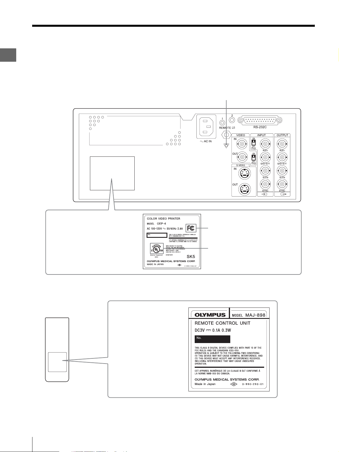
Labels and Symbols
Safety-related labels and symbols are attached to this
instrument (OEP-4 color video printer) at the locations
shown below.
Color video printer (OEP-4)
If labels or symbols are missing or illegible, contact
Olympus.
Equipotential terminal
Electrical rating
The product name, rated voltage and
frequency are shown.
Remote control unit (MAJ-898)
Electrical rating
The product name,
rated voltage and
product number are
shown.
FCC mark
C-UL mark
4
Labels and Symbols
Page 5

Important Information –
Please Read Before Use
Intended Use
This instrument, that is, OEP-4 color video printer, has
been designed to be used with Olympus endoscopes,
video system centers, camera control units and
endoscopic ultrasound centers for endoscopic diagnosis
and printing for endoscopic images.
Do not use this instrument for any purpose other than its
intended use.
Ultrasound center
The ultrasound center converts the ultrasonic signals
from an ultrasonic endoscope or probe into monitor
images.
SDTV
Standard Definition Television. It is the format used by
ordinary television systems.
HDTV
High Definition Television. It is a format featuring
higher image definition than the SDTV format.
Color printing pack
Set of ink ribbon and print sheets used to print pictures
on this instrument.
Instruction Manual
This instruction manual contains essential information
on using this instrument safely and effectively. Before
use, thoroughly review this manual and the manuals of
all equipment which will be used during the procedure
and use the equipment as instructed.
In addition, the “INSTRUCTIONS” for this instrument
are incorporated by “BASIC” and “ADVANCED.”
This “INSTRUCTIONS” is “BASIC,” and provides the
most basic information about this instrument.
More detailed information is described in
“ADVANCED.” Refer to “ADVANCED” if necessary.
Keep this and all related instruction manuals in a safe,
accessible location. If you have any questions or
comments about any information in this manual, please
contact Olympus.
Terms used in this manual
Wall mains socket outlet
An electrical outlet that has a terminal used exclusively
for grounding.
Isolation transformer
The isolation transformer is a safety device that is used
to isolate non-insulated equipment with potentially high
leakage currents to decrease the possibility of electric
shock.
Freeze
The freeze function creates a stationary view of the
moving image.
Source image
Live image being input from the video signal input
source.
Memory image
Image stored in the memory of this instrument.
Capture
Stores the image, sent from connected equipment, in the
memory of this instrument for printing.
Wireless remote control
Remote control which operates this instrument by radio
communications.
Wired remote control
Remote control which operates this instrument by cable
connecting.
Instrument Compatibility
Refer to the “System Chart” on page 29 in the
“Appendix” to confirm that this instrument is
compatible with the ancillary equipment being used.
Using incompatible equipment can result in patient or
operator injury and/or equipment damage. It may also
impair the functionality of the instrument.
This instrument complies medical electrical equipment
edition 2 (IEC 60601-1-2 : 2001). However when
connecting with a instrument complies with medical
electrical equipment edition 1 (IEC 60601-1-2 : 1993),
the whole system complies edition 1. (See, “EMC
Information” on page 33 for EMC compliance level.)
Video system center/Video system/Camera
control unit
These are the devices used to convert the endoscopic
image captured using a videoscope, fiberscope or rigid
scope into the signal to be output to the monitor device.
Important Information – Please Read Before Use
5
Page 6

Repair and Modification
Dangers, Warnings and Cautions
This instrument does not contain any user-serviceable
parts. Do not disassemble, modify or attempt to repair it;
patient or operator injury and/or equipment damage can
result.
Some problems that appear to be malfunctions may be
correctable by referring to “Chapter 7 Troubleshooting”
in “INSTRUCTIONS (ADVANCED).” If the problem
cannot be resolved using the information in Chapter 7 in
“INSTRUCTIONS (ADVANCED),” contact Olympus.
Signal Words
The following signal words are used throughout this
manual:
DANGER
Indicates an imminently hazardous situation which, if
not avoided, will result in death or serious injury.
WAR NING
Indicates a potentially hazardous situation which, if not
avoided, could result in death or serious injury.
CAUTION
Follow the dangers, warnings and cautions given below
when handling this instrument. This information is to be
supplemented by the dangers, warnings and cautions
given in each chapter.
Especially, about a power supply, refer to “2.4
Connection to the AC Mains Power Supply” on page 13.
DANGER
• Strictly observe the following precautions. Failure to
do so may place the patient and medical personnel in
danger of an electric shock:
– Keep fluids away from all electrical equipment. If
fluids are spilled on or into this instrument,
immediately stop operating it and contact Olympus.
– Do not prepare, inspect or use this instrument with
wet hands.
• Never install and operate this instrument in locations
where:
– The concentration of oxygen is high.
– Oxidizing agents (such as nitrous oxide (N
2O)) are
present in the atmosphere.
– Flammable anesthetics are present in the
atmosphere.
Otherwise, explosion or fire may result because this
color video printer is not explosion-proof.
Indicates a potentially hazardous situation which, if not
avoided, may result in minor or moderate injury. It may
also be used to alert against unsafe practices or potential
equipment damage.
NOTE
Indicates additional helpful information.
WARNING
• Be sure to turn this instrument OFF and unplug the
power cord before proceeding to care and
maintenance of this instrument. If the power cord is
left plugged in, an electric shock may result.
• Never insert metal and/or thing which are easy to burn,
or do not drop it into this instrument inside from the
ventilation grills. Electric shock and/or fire may result.
Moreover, if something go into the inside of this
instrument, turn OFF the power immediately and stop
use, then disconnect the power cord and connecting
cables. Contact Olympus.
• When there are abnormally sound, smell and/or heat
from this instrument, stop use immediately and
contact Olympus.
CAUTION
• Do not use a pointed or hard object to press the
switches on the front panel and/or remote control unit
(MAJ-898). This may damage the switches.
• Do not use this instrument roughly. Otherwise,
equipment damage, patient and operator injury can
occur.
• Strictly observe the following precautions. Otherwise,
damage and/or malfunction can occur.
– Do not touch the electrical contacts inside this
instrument’s terminals.
6
Important Information – Please Read Before Use
Page 7

– Do not apply excessive force to the terminals of this
instrument.
• When using spray-type medical agents such as
lubricate, anesthetic, or alcohol, use them away from
this instrument so that the medical agents will not fall
on this instrument. The medical agents possibly may
come into this instrument from its ventilation grills
and cause the failure.
• Do not use a humidifier by this instrument as dew
condensation possibly might occur and it may cause
the failure.
• Be sure that this instrument is not used adjacent to or
stacked with other equipment (other than the
components of this instrument or system) to avoid
electromagnetic interference.
• Electromagnetic interference may occur to this
instrument near equipment marked with the following
symbol or other portable and mobile radio
telecommunications equipment such as cellular
phones. If radio interference occurs, mitigation
measures may be necessary, such as reorienting or
relocating this instrument or shielding the location.
Important Information – Please Read Before Use
7
Page 8
1
Chapter 1 Package Contents
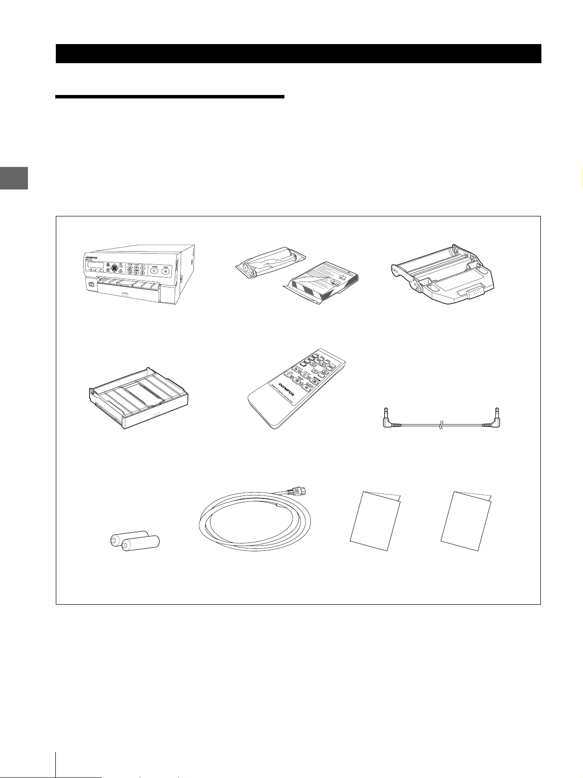
1.1 Checking the
Package Contents
Match all items in the package with the components
shown below. Inspect each item for damage. If this
instrument is damaged, a component is missing or you
Package Contents
have any questions, do not use this instrument;
immediately contact Olympus.
Color video printer
(OEP-4)
Paper tray Remote control unit
“AA”-size battery
(×2)
Trial pack (100 sheets) Ink ribbon holder
(MAJ-898)
Power cord INSTRUCTIONS
(BASIC)
Remote cable
INSTRUCTIONS
(ADVANCED)
8
1.1 Checking the Package Contents
Page 9

Chapter 2 Installation and Connection
Prepare this instrument and compatible equipment
(shown in the “System Chart” on page 29 in
“Appendix”) before each use, and refer to the instruction
manuals of each system component. Install and connect
the equipment as follows:
In addition, this “INSTRUCTIONS (BASIC)” explains
the EVIS EXERA video system center (CV-160) and the
VISERA video system center (OTV-S7V). For other
equipment, refer to “Chapter 2 Installation and
Connection” in “INSTRUCTIONS (ADVANCED).”
WARNING
• Review this chapter thoroughly before each use. If the
equipment is not properly prepared before each use,
equipment damage, patient and operator injury and/or
fire can occur.
• When non-medical electrical ancillary equipment is
used, connect its power cord via an isolation
transformer prior to connecting it to this video system
center. Failure to do so can cause electric shock, burns
and/or fire.
• Use this instrument and the color printing pack (UPC-
55) under the conditions described in “Operating and
Storage Environment” on page 31 and
“Specifications” on page 31 in “Appendix”.
Otherwise, improper performance, compromised
safety and/or equipment damage may result.
• Connect the power cord to a wall mains socket outlet
and connecting cables to each equipment firmly. If do
not connect correctly, fire or electric shock may result.
2.1 Installation of the
Color Video Printer
(OEP-4)
CAUTION
• Do not place any object on the top of this instrument.
Otherwise, equipment damage may result.
• Keep the ventilation grilles of this instrument clear.
Blockage may cause overheating and equipment
damage.
• Place this instrument on a stable and level surface.
Otherwise, this instrument topple down or drop.
• If a trolley other than the mobile workstation (WMN60) is used, confirm that the trolley can withstand the
weight of the equipment installed on it.
• This instrument cannot be used in every length.
Unstable operation, damage and/or abnormal printing
may result.
• Do not install this instrument near a source of strong
magnetic wave (microwave treatment device, short
wave treatment device, MRI, radio equipment, etc.).
Otherwise, this instrument may cause malfunction.
2
Installation and Connection
CAUTION
• Turn OFF all equipments before connecting them.
Otherwise, equipment damage or malfunction may
result.
• Use appropriate cables. Otherwise, equipment
damage or malfunction may result.
• The cables should not be sharply bent, pulled, twisted
or crushed.
• When you connect another piece of video equipment
between this instrument and the video system center,
be sure not to turn off the power of the video
equipment while this instrument is being used. If you
turn off the power of the video equipment, the video
signal may not be input to this instrument properly,
and this instrument may not work correctly, depending
on the video equipment connected.
2.1 Installation of the Color Video Printer (OEP-4)
9
Page 10
2
Installation and Connection
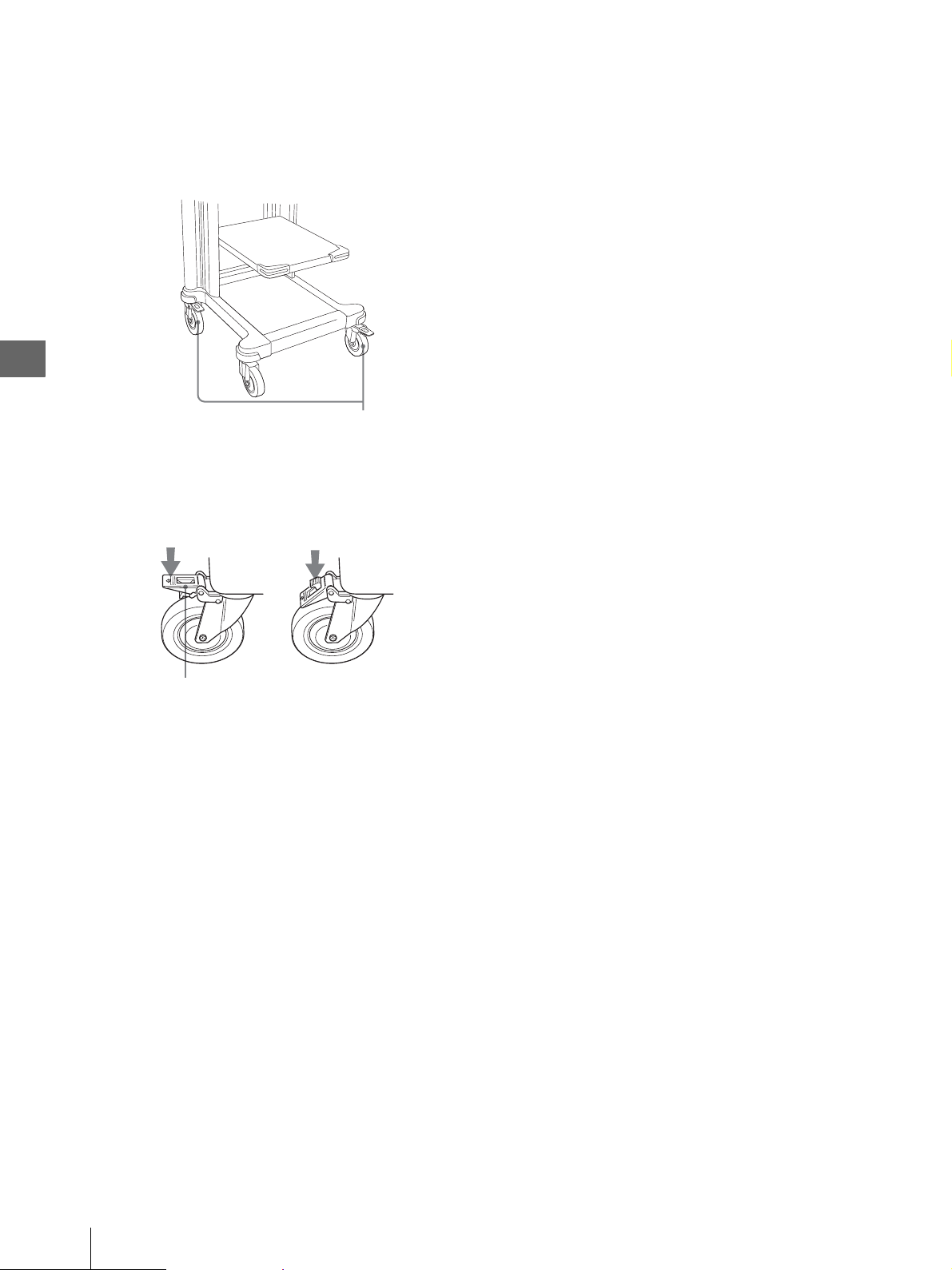
Installation on the mobile workstation
(WM-N60)
1
Place the mobile workstation on a level surface.
Lock the caster brakes by pushing them down (see
Figure 2.1).
Caster
m
Engaging the caster
brakes
Caster brake
Figure 2.1
2
Install the mobile shelf of the mobile workstation
according to the configuration of the equipment
installed on it as described in the mobile
workstation’s instruction manual.
3
Place the color video printer (OEP-4) on the mobile
shelf of the mobile workstation.
4
Be sure the portion of the color video printer (OEP-
4) does not contact with the mobile workstation,
etc., when you attach or remove the paper tray, or
open the front door.
If the color video printer (OEP-4) comes into
physical contact with the mobile workstation, etc.,
move the color video printer (OEP-4) to a location
where it will not contact with the mobile
workstation.
Releasing the
caster brakes
10
2.1 Installation of the Color Video Printer (OEP-4)
Page 11
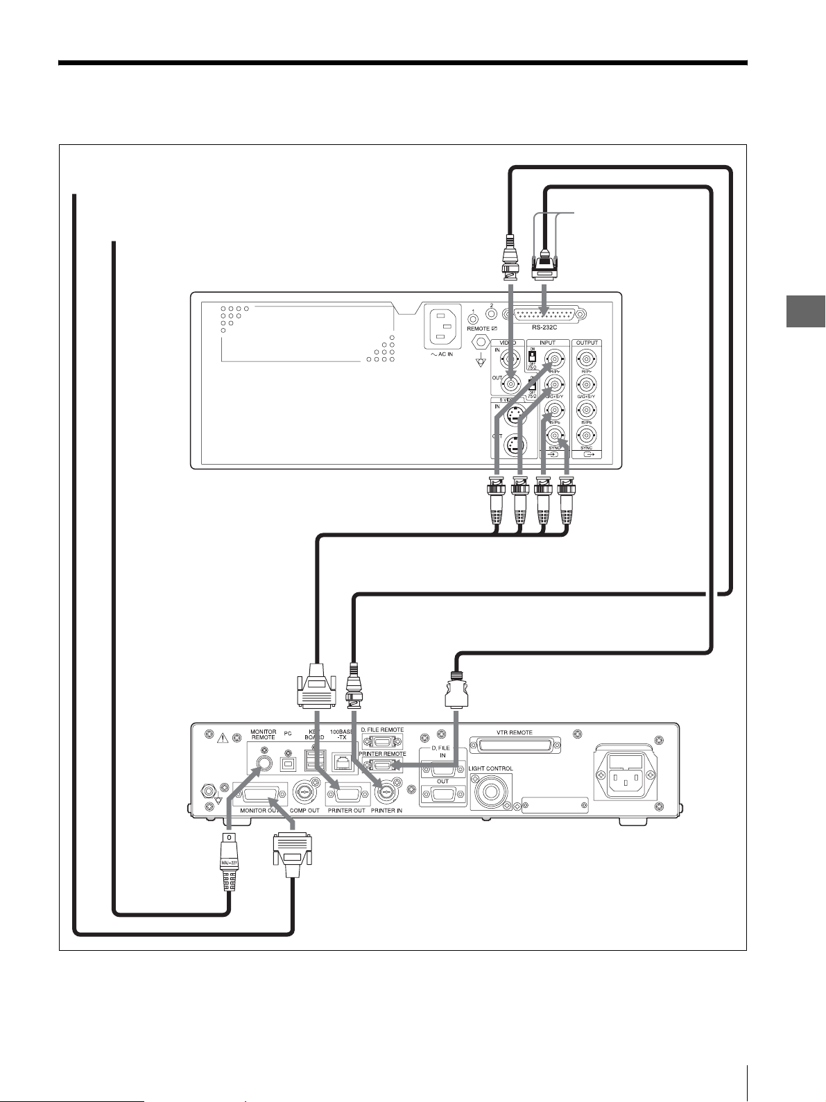
2.2 Connection of the EVIS EXERA Video System
Center (CV-160)
To RGB, Y/C, or VIDEO input terminal of a monitor
Attach the two black
To Remote terminal of a monitor
screws, provided with the
remote cable (MH-995).
Color video printer (OEP-4)
RGB cable (MH-984)
PRINTER
OUT
terminal
INPUT terminals
PRINTER IN
terminal
VIDEO OUT
terminal
PRINTER
REMOTE
terminal
RS-232C terminal
2
Installation and Connection
RGBS
BNC cable (MB-677)
Remote cable (MH-995)
Monitor
remote cable
Monitor Cable
MONITOR
REMOTE
terminal
MONITOR OUT
terminal
Figure 2.2
EVIS EXERA video system center (CV-160)
2.2 Connection of the EVIS EXERA Video System Center (CV-160)
11
Page 12
2
Installation and Connection
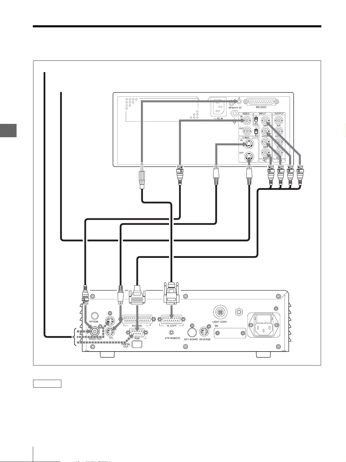
2.3 Connection of the VISERA Video System Center
(OTV-S7V)
To a monitor
To Y/C input terminal of
a monitor
Color video printer (OEP-4)
INPUT
terminal
VIDEO OUT
terminal
REMOTE 2
terminal
OEP cable (MH-987)
BNC cable (MB-677)
Y/C
terminal
VIDEO IN
terminal
RGB OUT
terminal
S VIDEO
IN
terminal
Y/C cable (MH-985)
RGB cable (MH-984)
H.COPY
terminal
S VIDEO
OUT
terminal
SBGR
Y/C cable
VISERA Video System Center (OTV-S7V)
NOTE
• It can be used if any one of an RGB cable, a Y/C cable,
and the BNC cable is connected between this
instrument and VISERA video system center (OTVS7V).
12
2.3 Connection of the VISERA Video System Center (OTV-S7V)
Figure 2.3
• Refer to the instruction manual of VISERA video
system center (OTV-S7V) for connection of VISERA
video system center (OTV-S7V) and the monitor.
Page 13

2.4 Connection to the
AC Mains Power
Supply
DANGER
Always power this instrument from a wall mains socket
outlet that has an exclusive terminal for grounding this
instrument. Otherwise, fire or electric shock may result.
WARNING
• Strictly observe the following precautions for the
power cord. Damaging the power cord may result in
fire or an electric shock:
Moreover, if power cord is damaged, turn OFF the
power and stop using this instrument immediately and
contact Olympus.
– When placing the power cord, take care that it is not
crushed in the space between this instrument and a
wall, mobile workstation or a shelf.
– Do not modify or damage the power cord.
– Do not use damaged power cord.
– Do not stretch or place a heavy object on the power
cord.
– Do not place the power cord near heating equipment
or expose it to excessive heat.
– Always grasp and pull the plug when unplugging the
power cord. Do not pull on the cord itself.
• Always use this instrument with the voltage specified
in “Specifications” on page 31 in “Appendix”.
Supplying a non-specified voltage, fire and/or electric
shock may result.
• When there are metal and/or dust on power cord plug
or near the plug of the power cord, disconnect the
power cord and remove them with the dry cloth. If it is
then used, fire and/or electric shock may result.
• Always use the power cord and connection cables that
were shipped with this instrument or mobile
workstation. Using other power cords or connection
cables, electric shock and/or malfunction may result.
• Do not allow the power plug to become wet. Also do
not hold the power cord with a wet hand. A wet power
plug may cause electric shock.
• Confirm that the wall mains socket outlet has adequate
electrical capacities. Failure to do so may cause fire or
a power failure to all of the equipment connected to
the same power circuit.
• Do not bend, pull or twist the power cord. Equipment
damage including separation of the power plug and
disconnection of the cord wire as well as fire or
electric shock can result.
• Do not use the adapter which power cord plug
changed into 3-pin to 2-pin. Electric shock may result.
CAUTION
• Use the power supply which suits the specification in
“Specifications” on page 31 in “Appendix”.
Otherwise, malfunction may result.
• Be sure to connect the power plug securely.
Otherwise, the equipment will not function.
• Do not use of a power supply with insufficient
electrical capacities. Otherwise, malfunction may
result.
• Be fully careful for the power cord not to disconnect.
If the power cord disconnects while in use, the picture
under printing disappears or it may not be printed
correctly.
• Do not connect or disconnect the power cord while
power ON. Otherwise, malfunction may result.
To connect to the AC mains power supply
1
Confirm that the color video printer (OEP-4) is
turned OFF.
2
Connect the power cord provided with the mobile
workstation to the AC mains power inlet of the
color video printer (OEP-4) (see Figure 2.4).
AC mains power inlet
Power cord
Figure 2.4
3
Connect the power cords of the ancillary equipment
to the mobile workstation by referring to its
instruction manual.
4
Connect the power cord of the mobile workstation
to a wall mains socket outlet.
2
Installation and Connection
2.4 Connection to the AC Mains Power Supply
13
Page 14

3
Chapter 3 Inspection Before Use
WAR NING
Before each case, inspect this instrument as instructed
below. Inspect other equipment to be used with this
instrument as instructed in their respective instruction
manuals. Should the slightest irregularity be suspected,
do not use this instrument and see “Chapter 7
Troubleshooting” in “INSTRUCTIONS
(ADVANCED).” If the irregularity is still suspected
after consulting Chapter 7 in “INSTRUCTIONS
(ADVANCED),” contact Olympus.
Damage or irregularity may compromise patient or user
safety and may result in more severe equipment damage.
Prepare this instrument and other equipment (shown in
Inspection Before Use
“System Chart” on page 29 in the “Appendix”) to be
used with this instrument for each particular case. Refer
to the respective instruction manual for each piece of
ancillary equipment.
3.1 Inspection of the
Power Supply
1
Press the power switch to turn ON the color video
printer (OEP-4) (see Figure 3.1).
2
Confirm that the PRINT lamp is lit and then turns
off (see Figure 3.1).
3
Press the power switch again.
4
Confirm that the LCD panel turns off.
PRINT lamp
LCD panel
Power switch
Figure 3.1
If the power fails to come on
If the power fails to come on, inspect according to
“Chapter 7 Troubleshooting” in “INSTRUCTIONS
(ADVANCED).”
When a power supply still is not tuned ON, contact
Olympus.
14
3.1 Inspection of the Power Supply
Page 15

3.2 Installation of the
Color Printing Pack
(UPC-55)
Install the separately available color printing pack
(UPC-55) on this instrument. In addition, never use the
other printing packs except UPC-55. For the first time
using this instrument, supplied trial pack can be used for
an operation check.
CAUTION
The color printing pack (UPC-55) is a set of an ink
ribbon and print sheets. Be sure to use the ink ribbon and
print sheets provided in the same set. Otherwise, the
color tones in the printed pictures may be abnormal.
Always replace the ink ribbon and print sheets
simultaneously, even if either of them is remaining.
Otherwise, the color tones in the printed pictures may be
abnormal.
Installation of the Ink Ribbon
Install the ink ribbon on the provided ink ribbon holder.
1
Open the front door by flipping it downward from
the top edge (see Figure 3.2).
Front door
2
Take out the ink ribbon holder (see Figure 3.3).
Ink ribbon holder
Figure 3.3
CAUTION
• Do not apply an excessive force to the ink ribbon
holder. Otherwise, damage may result.
• Remove the ink ribbon holder straight and level
from this instrument. If you take out the ink
ribbon holder at a slant, this instrument and/or the
ink ribbon holder may cause damage.
3
Remove the used ink ribbon from the ink ribbon
holder.
While pushing the take-up side gear (gray ink
ribbon gear) in the direction of the arrow, remove
the ink ribbon from the take-up side gear shaft. Also
remove it from the feed side gear shaft by pushing
the feed side gear (white ink ribbon gear) in the
direction of the arrow (see Figure 3.4).
Gear (Gray)
3
Inspection Before Use
Figure 3.2
CAUTION
• Be careful not to have your hand caught by the
front door. Otherwise, injury may result.
• Do not apply an excessive force to the front door.
Otherwise, damage may result.
Gear (White)
Caution label
Figure 3.4
CAUTION
Do not attempt to reuse a used ink ribbon. Also do
not attempt rewind and reuse an ink ribbon.
Otherwise, the printing will not only be incorrect
but damage to this instrument may also occur.
NOTE
Also refer to the caution label on the ink ribbon
holder.
3.2 Installation of the Color Printing Pack (UPC-55)
15
Page 16

3
4
Set a new ink ribbon on the ink ribbon holder.
Hold the ink ribbon right and remove the gear cover
(see Figure 3.5).
Gear cover
6
Figure 3.5
CAUTION
Inspection Before Use
Do not touch the surface of the ink ribbon for longer
than is necessary. Do not leave it in a dusty
environment. If smudges or dust attach to the ink
ribbon, printing will not only be incorrect but also
damage to this instrument may occur.
NOTE
Also refer to the caution label on the ink ribbon
holder.
Turn the gears in the arrow direction until the
magenta section of the ink ribbon appears all over
to remove slack from the ink ribbon (see Figure
3.7).
Gears
Magenta section
Caution label
Figure 3.7
5
In first, fit the white gear into the ink ribbon, next
fit the gray gear into the ink ribbon (see Figure 3.6).
Gear (White)
Caution label
m
Gear (Gray)
NOTE
Also refer to the caution label on the ink ribbon
holder.
7
Push the ink ribbon holder all the way into the color
video printer (OEP-4) (see Figure 3.8).
Figure 3.8
WARNING
Do not insert or put something except ink ribbon
holder into the paper exit. Otherwise, damage may
result, furthermore fire and/or electric shock may
result.
Figure 3.6
16
3.2 Installation of the Color Printing Pack (UPC-55)
Caution label
CAUTION
Push the ink ribbon holder into this instrument
straight and level. If you push the ink ribbon holder
in at a slant, the ink ribbon may be torn, or this
instrument and/or the ink ribbon holder may cause
damage.
Page 17

8
Close the front door of the color video printer
(OEP-4) (see Figure 3.9).
Front door
1
Press the PUSH EJECT area of the paper tray and
take out the paper tray from the color video printer
(OEP-4) (see Figure 3.11).
Figure 3.9
CAUTION
• Be careful not to have your hand caught by the
front door. Otherwise, injury may result.
• Do not apply an excessive force to the front door.
Otherwise, damage may result.
If the ink ribbon is torn in the middle
1
Connect the torn sections with transparent plastic
tape (see Figure 3.10).
2
Turn the gray gear on the take-up side in the
direction of the arrow direction to take up the ink
ribbon until the plastic tape is invisible (see Figure
3.10). Be sure to remove slack from the ink ribbon.
Gear (Gray)
Figure 3.11
CAUTION
• When attaching or detaching the paper tray, be
careful not to move this instrument together.
Otherwise, this instrument may drop and cause
injury or may malfunction.
• Do not apply an excessive force to the paper tray.
Otherwise, damage may result.
• Remove the paper tray straight and level from this
instrument. If you take out the paper tray at a
slant, it may result in damage to the paper tray or
to this instrument.
2
Flip through the print sheets together with the
protective sheet (see Figure 3.12).
3
Inspection Before Use
Plastic tape
Figure 3.10
Installation of the Print Sheets
NOTE
When storing the print sheets by removing them from
this instrument, put the print sheets in its original
package bag or a similar bag according to the instruction
manuals supplied with the color printing pack (UPC-
55).
Figure 3.12
CAUTION
• Do not touch the print surface of print sheet with
a hand. Always handle the print sheets without
removing the print surface protective sheet. If
smudges or dust attach to the print surface,
printing will not only be incorrect but also
damage to this instrument may occur.
• If you use print sheets that have stuck to each
other, these stuck print sheets will be double-fed
into this instrument and may cause frequent paper
jamming.
• Do not bend and/or fold print sheets when you
flip print sheets. Also, do not use extremely
warped print sheets. Otherwise, paper jam may
result.
3.2 Installation of the Color Printing Pack (UPC-55)
17
Page 18

3
Open the cover of the paper tray.
If print sheets remain in the paper tray, remove
them.
Align the direction of the arrow of the positioning
mark on the protective sheet with that of the arrow
of the positioning mark on the paper tray, and place
the print sheets in the paper tray together with the
protective sheet, so that the print surfaces face
upward (see Figure 3.13).
Positioning mark
5
Insert the paper tray into the color video printer
(OEP-4) until it clicks (see Figure 3.15).
3
Protective sheet
CAUTION
• When attaching or detaching the paper tray, be
Inspection Before Use
Positioning mark
Figure 3.13
CAUTION
• Set print sheets so that they accurately fit the
paper tray. Otherwise, paper jam may result.
• Do not add additional print sheets to the paper
tray while paper sheets remain. If you add
additional print sheets, this may cause paper
jamming.
• Do not reuse the print sheets left in the paper tray.
NOTE
Also refer to the indications on the paper tray and
the protective sheet.
careful not to move this instrument together.
Otherwise, this instrument may drop and cause
injury or may malfunction.
• If the paper tray cannot be inserted all the way,
check if print sheet is remaining in the paper tray
slot. If any is remaining, remove it and do not
attempt to reuse it.
• Do not enter your hand into the paper exit.
Otherwise, injury may result by involving in the
internal roller.
• Insert the paper tray into this instrument straight
and level. If you insert the paper tray at a slant, it
may result in damage to the paper tray or to this
instrument. Also, abnormal noise or paper
jamming may occur during printing.
6
Pull out the stopper of the paper tray until it clicks
(see Figure 3.16).
Figure 3.15
4
Remove the protective sheet (see Figure 3.14).
Figure 3.14
18
3.2 Installation of the Color Printing Pack (UPC-55)
Stopper
Figure 3.16
Page 19

3.3 Setup of the Connected Equipment
This document, “INSTRUCTIONS (BASIC),” explains
the EVIS EXERA video system center (CV-160) and the
VISERA video system center (OTV-S7V).
Refer to the instruction manuals of the connected
equipment and set them up as required for use with this
instrument.
Refer to “INSTRUCTIONS (ADVANCED)” when you
use equipment other than the equipment introduced in
“INSTRUCTIONS (BASIC).”
Ta b l e 3 . 1
Connected Device Instruction Manual
References
CV-160 “6.9 Image recording and
playback”
“Using a video printer”
“Operation from the
keyboard”
“5.3 System setup”
“Printer settings”
“5.4 User presets”
“Setting [User Preset –
Edit Data] menu”
“Setting endoscope
remote switch functions”
OTV-S7V “5.12 Remote control
switches”
“5.13 Setting a function
to the keyboard”
Setup Item Setup Note
“#PER PAGE” switch on
the keyboard.
“PRINT QTY.” switch on
the keyboard.
“Type” “OEP3” Select the printer type. Be sure to
“Qty. “N”” “4” – “ 9” Select the print quantity when the
“Caption” Max. 40 characters. Input the characters to be printed
“Scope remote switches”
“Switch 1”
“Switch 2”
“Switch 3”
“Switch 4”
Remote control switch on
the videoscope or camera
head
“F4” key “REL.+DIG. CAP.”
From “1,” “2,” “4”,
“N”
From “1,” “2,” “3”,
“N”
“Printer”
“P.Back”
“REL.+DIG. CAP.”
“RELEASE”
“RELEASE”
Select the number of multipicture images. Select any one
except “16.”
Set the number of print quantity.
Print quantity is set up from a
menu when it is set as “N,”
according to “Printer settings” in
“5.3 System setup.” Select any
setting.
set “Type” to “OEP3” when using
this instrument.
“Print quantity indicator” on the
keyboard is set to “N.” Select any
setting, as required.
in the margin of print sheet.
Select the functions to be
controlled from the scope
switches on the videoscope or
OES video converter. Select any
setting, as required.
Select the function to be
controlled from the remote
control switch on the videoscope
or camera head. Select any
setting, as required.
Select the function to be activated
with the “F4” key on the
keyboard. Select any setting.
Input them, as required.
3
Inspection Before Use
3.3 Setup of the Connected Equipment
19
Page 20

3.4 Setting of the Rear
3.5 Inspection of the
3
Panel
Set the composite 75 Ω termination switch and RGB
75 Ω termination switch on the rear panel to ON (see
The LCD panel displays the information and messages
according to the conditions of this instrument.
LCD Panel Display
Figure 3.17).
CAUTION
When an error or warning message is displayed, take
Set to ON
proper measures refer to “Countermeasures Against
Messages” in “7.1 Troubleshooting Guide” in
“INSTRUCTIONS (ADVANCED).”
1
Turn the color video printer (OEP-4) ON as
described in “3.1 Inspection of the Power Supply”
on page 14.
2
Confirm that the LCD panel displays the startup
Inspection Before Use
message and that the display then changes as shown
in Figure 3.18.
For details of each item, refer to “INSTRUCTIONS
RGB 75 Ω termination switch
Composite 75 Ω termination switch
Figure 3.17
(ADVANCED).”
Startup message
Caption display
This field shows “C” when the printed picture is
set to contain a comment (caption).
Input signal display
This field shows the input
signal format being
selected (see Table 3.2).
Print quantity display
This field shows the
number of prints.
Memory page display
This field shows the
number of memory page
being selected.
Operation mode display
This field shows the operation mode of this
instrument.The number on the left is the number of
images used in multi-picture printing. Also, in case of
printed image with white frame, “F” is displayed on the
right side of the number of images. The number on the
right indicates the current position of the pointer. It is the
location where the image is stored next.
Remaining ink ribbon
display
This field shows the
remaining ink ribbon quantity.
Source/Memory display
This field shows “S”
when the source image
is displayed on the
monitor, and shows “M”
when the memory image
is displayed on the
monitor.
20
3.4 Setting of the Rear Panel / 3.5 Inspection of the LCD Panel Display
Figure 3.18
Page 21

Ta b l e 3 . 2
Display Input signal format
VIDEO VBS composite video
SVIDEO Y/C signals
SD RGB signals (SDTV)
HD RGB signals (HDTV)
SDAUTO Auto input detection (for SDTV input)
HDAUTO Auto input detection (for HDTV input)
3.6 Setup of This
Instrument
The procedures in this section describe the minimum
operations in case using with the EVIS EXERA video
system center (CV-160) or VISERA video system center
(OTV-S7V).
For other setups of this instrument, set them as desired
by “Chapter 5 System Setup” in “INSTRUCTIONS
(ADVANCED).”
Cursor keys “v” “V”
MENU button
LCD panel
“b” “B”
3
Inspection Before Use
Figure 3.19
1
Press the MENU button.
2
Perform setup of the color video printer (OEP-4)
and confirm in the following procedures according
to the connected equipment.
Ta b l e 3 . 3
Connecting Procedure
CV-160 1 Press “B” until the LCD panel
shows “BASIC SETUP.”
2 Press “V” until the LCD panel
shows “INPUT SEL.”
3 Confirm that uppercase letters
“COMPONENT” are displayed
below “INPUT SEL.”
OTV-S7 V 1 Press “B” until the LCD panel
shows “BASIC SETUP.”
2 Press “V” until the LCD panel
shows “INPUT SEL.”
3 Press “B” until the input signal
format is displayed in uppercase
letters below “INPUT SEL.”
VIDEO: Inputs the signal in the
composite signal format.
S-VIDEO: Inputs the signal in the
Y/C signal format.
COMPONENT: Inputs the signal in
the component signal format.
3
Press the MENU button.
The LCD panel should return to the previous
display.
3.6 Setup of This Instrument
21
Page 22

3.7 Inspection of the Monitor Display
3
The monitor displays information and messages
according to the conditions of this instrument.
3
When the color video printer (OEP-4) is connected
to a video system center, display the image from the
color video printer (OEP-4) on the monitor by
Inspection of the output image
referring to the instruction manuals for the video
system center and monitor.
1
Turn the color video printer (OEP-4) ON as
described in “3.1 Inspection of the Power Supply”
on page 14.
2
Display the output image from the color video
4
Confirm that the monitor first displays the startup
message, and then shows the display as shown in
Figure 3.20. For details of each item, refer to
“INSTRUCTIONS (ADVANCED).”
printer (OEP-4) on the monitor.
Message display 1
This field shows less urgent
messages that may be
displayed during normal use.
Inspection Before Use
Caption display
This field shows “C” when the
printed picture is set to contain a
comment (caption).
White frame display
It is displayed in case of printed
picture with white frame.
Print quantity display
This field shows the number of
prints. It blinks during printing.
Message display 2
This field shows more urgent
message.
Remaining ink ribbon display
This field shows the remaining
ink ribbon quantity.
Pointers
These indicate the locations
where the images are stored.
They can be moved using the
cursor keys (“v” “V” “b” “B”).
The green blinking pointer
indicates the location where the
image is stored next. The
pointers are not displayed on the
monitor when number of multipicture images is set to “1.”
Memory page display
This field shows the number of
memory page being selected.
The memory page number
blinks during printing or when it
is reserved for printing.
CAUTION
Operation mode display
This field shows the operation mode of this
instrument. The symbol on the left shows how the
screen is split for displaying the multi-picture images
to be printed.
Display Number of multi-picture images
1
2
4
8
Figure 3.20
When messages are displayed on the message display 1
or the message display 2, inspect refer to
“Countermeasures Against Messages” in “7.1
Troubleshooting Guide” in “INSTRUCTIONS
(ADVANCED).”
Source/Memory display
This field shows “S” when the
source image is displayed on the
monitor, and shows “M” when
the memory image is displayed
on the monitor.
22
3.7 Inspection of the Monitor Display
Page 23

Inspection of the CVP counter
When this instrument is connected to the following
equipment, perform the inspection of the CVP counter.
– EVIS EXERA video system center (CV-160)
– EVIS video system center (CV-240, CV-140)
1
Display the output image from the video system
center on the monitor by referring to the instruction
manuals for the video system center and the
monitor.
2
Confirm that the monitor screen displays the “CVP
counter” (see Figure 3.21).
CVP counter
Figure 3.21
3
If the “CVP counter” is not displayed on the
monitor screen, refer to “Irregularity: The CVP
counter is not displayed” in “7.1 Troubleshooting
Guide” in “INSTRUCTIONS (ADVANCED).”
3.8 Check of the Printed
Picture
Check whether the printed picture is desired.
1
Observe, for example, the palm of your hand using
the endoscope, while referring to the instruction
manual of any connected equipment.
2
Capture a picture, while referring to the instruction
manual of any connected equipment.
Confirm that the number displayed on the “CVP
counter” is increased by one. If the number is not
increased, refer to “Irregularity: The number
displayed on the CVP counter does not increase
even if an image has been captured” in “7.1
Troubleshooting Guide” in “INSTRUCTIONS
(ADVANCED).”
3
Print.
4
Check that the printed picture is desired picture
quality.
When it is not desired picture quality, adjust the
picture quality, referring to “Chapter 5 System
Setup” in “INSTRUCTIONS (ADVANCED).”
After adjustment, print and check again.
3
Inspection Before Use
3.8 Check of the Printed Picture
23
Page 24

4
Operation
Chapter 4 Operation
WAR NING
• Do not use this instrument in a location exposed to
direct strong electromagnetic radiations (for example,
microwave treatment device, short wave treatment
device, MRI or radio equipment). Electromagnetic
radiation can interfere with the monitor display.
• It is recommended to use only Olympus highfrequency electrosurgical equipment with this
instrument. Non-Olympus equipment can cause
interference on the monitor display or a loss of the
endoscopic image.
NOTE
• Prepare the spare color printing pack (UPC-55), just in
case it is finished.
• The illustration of the monitor has not indicated the
endoscopic image for legibility.
4.1 Turning the Power
ON
Press the power switch (see Figure 4.1).
Power switch
Figure 4.1
CAUTION
When an error or warning message is displayed, take
proper measures, referring to “Countermeasures
Against Messages” in “7.1 Troubleshooting Guide” in
“INSTRUCTIONS (ADVANCED).”
NOTE
For information and messages displayed on the monitor
and the LCD panel, see “3.5 Inspection of the LCD
Panel Display” on page 20 and “3.7 Inspection of the
Monitor Display” on page 22.
24
4.1 Turning the Power ON
Page 25

4.2 Control from the
Connected
Equipment
This document, “INSTRUCTIONS (BASIC),” explains
the use of the EVIS EXERA video system center (CV-
160) and the VISERA video system center (OTV-SV7)
with this instrument.
Refer to “INSTRUCTIONS (ADVANCED)” when you
use equipment other than the equipment introduced in
“INSTRUCTIONS (BASIC)” or when you attempt to
control this instrument from the panel or the remote
control unit (MAJ-898).
CAUTION
• When this instrument is controlled from the EVIS
EXERA video system center (CV-160), do not operate
following tasks from this instrument and the remote
control unit (MAJ-898).
– Setting up the print quantity
– Setting up the number of multi-picture
– Clearing the captured image
– Changing memory page
– Moving the pointer
Cause the difference between settings of the EVIS
EXERA video system center (CV-160) and settings of
this instrument, desired operation may not be carried
out or image data may disappear.
• Do not set the number of multi-picture images to “16”
from the EVIS EXERA video system center (CV-
160). If it is set as “16,” it will be set as “1.”
• If the EVIS EXERA video system center (CV-160) is
set as “8,” the image cannot be captured during
printing, because the memory page is not switched.
• Do not turn OFF while printing is in progress.
Otherwise, paper jam and/or malfunction may result.
• Do not open the front door or take out the paper tray
while printing is in progress. Otherwise, paper jam
and/or malfunction may result.
• Do not leave 10 or more print sheets on the paper exit.
Otherwise, paper jam may result. Also, even when the
number of print sheets is less than 10, message
“REMOVE PRINTS” may be displayed on the
monitor and LCD panel and printing is interrupted
depending on the print sheet conditions. If this occurs,
remove the print sheets from the paper exit. Printing
will resume automatically.
• If you turn this instrument OFF while the PRINT lamp
is lit, the ink ribbon quantity displayed on the
remaining ink ribbon display on the LCD panel and/or
the monitor may not match the actual ink ribbon
quantity remaining.
Be sure to turn this instrument OFF after the printing
is completed and the PRINT lamp turns off.
NOTE
• Refer to the instruction manuals supplied with
connected equipment.
• If print sheets jam during printing, take the
measures recommended in to “4.3 In the Case of
a Paper Jam” on page 26.
• Cannot store an image in the memory page that is
printing in progress or reserved for printing. Wait
until the printing completes.
• If you open the front door during printing,
printing is interrupted. If you close the front door,
the print sheet being printed is ejected. To print
again, press the PRINT button.
• When the remaining print sheets in the paper tray
decreases, a rattling sound may be heard during
printing. This is not a malfunction.
• Depending on the environment in which this
instrument is used, or on the condition of the print
sheets, the printed sheets output on the paper exit
may go over the stopper and drop from the paper
exit. Printed sheets may slide between previously
ejected print sheets, and may not stack up in
printed order.
1
Set up the connected equipment as shown in Table
3.1 in “3.3 Setup of the Connected Equipment” on
page 19.
2
Set up the color video printer (OEP-4) according to
the connected equipment as described in “3.6 Setup
of This Instrument” on page 21.
3
Control as described in the instruction manuals for
the connected equipment (see Table 4.1).
Ta b l e 4 . 1
connected
equipment
CV-160 “6.9 Image recording and playback”
OTV-S7V “5.21 Photography and display with
The part indicated to the
instructions manual
“Using a video printer”
color video printer OEP-3/OEP (not
available in some countries)”
4
Operation
4.2 Control from the Connected Equipment
25
Page 26

4
Operation
4.3 In the Case of a
Paper Jam
If paper jam occurs in the middle of printing, correct it
as described below.
The flash memory is built into this instrument to store all
of the image data stored in the memory pages and all of
the current settings of this instrument, in case the print
sheet jams unexpectedly. When the power of this
instrument is turned OFF, image data stored in the
memory pages is cleared. However, data stored in the
flash memory will not be cleared even if the power is
turned OFF.
Removing the Jammed Paper Sheet
When paper jam occurs, message “SAVING IMAGES..”
is displayed together with the error message, and the
images captured in this instrument are stored together
with the menu setups in the flash memory. When these
message have disappeared, remove the jammed paper in
the following steps.
2
Push the PUSH EJECT area on the paper tray and
take out the paper tray (see Figure 4.3).
Figure 4.3
3
Remove the jammed paper sheet (see Figure 4.4).
CAUTION
Do not turn OFF this instrument during the message is
displayed. If the power is turned OFF, a image data is not
only saved in the flash memory, but damage may result.
1
Press the power switch to turn OFF (see Figure 4.2).
Power switch
Figure 4.2
Figure 4.4
CAUTION
Do not reuse the removed print sheet. Paper jam
may occur.
4
Confirm that the print sheets correctly on the paper
tray.
If not, place the print sheets correctly on the paper
tray.
5
Install the paper tray.
If the jammed paper is not removed in the
above-mentioned procedure
1
Besure to turn OFF the power, and disconnect the
power cord and other connecting cables.
2
Remove the ink ribbon cartridge and the paper tray
from the color video printer (OEP-4) and then turn
the color video printer (OEP-4) upside down.
26
4.3 In the Case of a Paper Jam
Page 27

3
Remove the one screw with which the back cover
plate is secured, using a coin and so on (see Figure
4.5).
6
Replace the back cover plate (see Figure 4.8).
Figure 4.8
Figure 4.5
4
Pull the back cover plate up and remove it from the
main body (see Figure 4.6).
Figure 4.6
5
Remove the jammed paper slowly (see Figure 4.7).
7
Secure the back cover plate by the screw removed,
using a coin (see Figure 4.9).
Confirm that the screw holes of back side of the
main body and the back cover plate match before
securing them.
Figure 4.9
8
Reset the paper tray and ink ribbon holder into the
color video printer (OEP-4).
Reconnect the power cord and other connecting
cables as they were.
Confirm that any connecting cables and the power
cord are securely connected.
4
Operation
Figure 4.7
NOTE
If jammed paper cannot be not removed or error
message is displayed even after taking the above
procedure, stop using this instrument and contact
Olympus.
Restart Printing
Even when paper jam occurs in the middle of printing,
the image of the print is held in the flash memory of this
instrument so it can be re-printed.
4.3 In the Case of a Paper Jam
27
Page 28

4
Operation
CAUTION
The image of the print stored in the flash memory is
overwritten each time paper jam occurs. If image data is
overwritten, you cannot print the image data stored
before the paper jam occurred.
1
Press the power switch to turn ON.
2
When message “RESTORE IMAGES? YES/NO”
is displayed on the monitor and the LCD panel,
press the “b” or “B” button to select “YES” and
press the EXEC button.
NOTE
If “NO” is selected in step 2, refer to “Setting
“STORE IMAGE”” in “5.15 Setup of the
FUNCTION SETUP Menu” in “INSTRUCTIONS
(ADVANCED)” to restore and print the image
manually.
3
Message “READING IMAGES” is displayed on
the monitor and the LCD panel. And then the
display returns to the normal display.
4.4 Exiting from
Examination
CAUTION
When this instrument is controlled from connected
equipment, the captured images will not be printed
automatically until their number reaches the set number
of multi-picture images. Confirm that there are no
unprinted images in the memory pages before turning
this instrument OFF. Once this instrument is turned
OFF, all of the images captured in the memory pages are
cleared and cannot be printed.
1
Display the memory image on the monitor, and
confirm that there are no images left unprinted in
memory page.
If there is any, print them.
2
After printing is completed, turn the color video
printer (OEP-4) OFF.
4
When image readout completes, message
“RESTORE FINISHED” is displayed on the
monitor and the LCD panel.
5
Select the memory page where images that you
want to print are stored.
6
Press the PRINT button to start printing.
NOTE
When you control the printer from the EVIS EXERA
video system center (CV-160) or the EVIS video system
center (CV-240 or CV-140), change the memory page or
print images using the keyboard of the connected
equipment.
For details, refer to the instruction manuals of the
connected equipment.
In only case other than the cases above, see “Selecting
the Memory Page” and “Printing” in “4.2 Control From
the Front Panel” in “INSTRUCTIONS (ADVANCED).”
28
4.4 Exiting from Examination
Page 29

Appendix
System Chart
The recommended combinations of equipment that can
be used with this instrument are listed below. New
products released after the introduction of this
instrument may also be compatible for use in
combination with it. For further details, contact
Olympus.
WARNING
If combinations of equipment other than those shown in
the following chart are used, the full responsibility is
assumed by the medical treatment facility.
Appendix
System Chart
29
Page 30

Mobile workstation (WM-N60)
High Definition Monitor
(OEV181H)
Color video monitor
(OEV143, OEV203)
EVIS EXERA Video System Center
(CV-160)
EVIS Video System Center
(CV-240, CV-140)
VISERA Video System Center (OTV-S7V)
3CCD Camera Control Unit
(OTV-SP1C, OTV-SP1C-G)
Camera Control Unit (OTV-SX2)
Appendix
Color video printer (OEP-4)
Remote control unit (MAJ-898)
High Definition LCD Monitor (OEV191H)
LCD Monitor (OEV191)
Video System (OTV-SI)
EUS EXERA Compact Enoscopic
Ultrasound Center (EU-C60)
30
System Chart
Products enclosed with the dotted
line conform to EMC (Ed.2).
EUS EXERA Enoscopic
Ultrasound Center (EU-M60)
Page 31

Operating and Storage Environment
Color video printer (OEP-4)
Operating
environment
Transport and
storage
environment
NOTE: Except the “trial pack.”
Color printing pack (UPC-55)
Operating
environment
Storage
environment
Ambient temperature 10 – 35°C (50 to
95°F)
Relative humidity 30 – 80% (without
condensation)
Atmospheric pressure 700 – 1060 hPa
(0.7 – 1.1 kgf/cm2)
(10.2 – 15.4 psia)
Ambient temperature –20 to +60°C (-4 to
140°F)
Relative humidity 20 – 90% (without
condensation)
Atmospheric pressure 700 – 1060 hPa
Ambient temperature 10 – 35°C (50 to
95°F)
Relative humidity 30 – 80% (without
condensation)
Atmospheric pressure 700 – 1060 hPa
Ambient temperature –20 to +30°C (-4 to
86°F)
Relative humidity 30 – 80% (without
condensation)
Atmospheric pressure 700 – 1060 hPa
Specifications
Item Specifications
Power supply Supply voltage 100 – 120 V AC
Voltage fluctuation ±10%
Supply frequency 50/60 Hz
Dimensions and
weight
Classification
(Electromedical
equipment)
Storage and
printing
Storage and
printing
Frequency
fluctuation
Input current 2.8 A
Dimensions 280(W) × 125(H) ×
Weight 9 kg
Type of protection
against electric
shock
Degree of
protection against
explosion
Printer pack UPC-55 only.
Printing method Dye sublimation
Paper size 178 x 152 mm (Special
Print area 2528H × 1920V dots
Resolution 379 dpi
Print speed Normal: Approx. 29
Multi-picture
splitting
Print quantity 1 to 10 copies
Image capturing
instruction
±1 Hz
398(D) mm
Class 1
Use prohibited in
flammable
environment.
“A5” size)
(169.4 × 128.6 mm)
sec.
High : Approx. 21 sec.
1, 2, 4 or 8
Image storage in
synchronism with the
capture signal from the
connected equipment.
Image storage in
synchronism with the
CAPTURE key on the
front panel.
Image storage in
synchronism with the
CAPTURE key on the
remote control unit
(MAJ-898).
Appendix
Operating and Storage Environment / Specifications
31
Page 32

Item Specifications
Input signal HDTV signal (1080/
59.94i):
RGB/YPbPr video
signal.
Y/C video signals
Composite video signal
Tolerance (75 Ω
termination)
RGB (HDTV) video
signals:
0 to 0.7 Vp-p (Video)
±0.3 Vp-p (Sync).
RGB video signals:
0 to 0.785 Vp-p.
Composite sync:
1.0 to 4.0 Vp-p.
Y/C video signals:
0 to 0.714 Vp-p.
Composite video:
0 to 0.714 Vp-p
Output signal (75 Ω termination)
Appendix
Memory save
after setup
Ye a r of
production
EMC Applicable
Setups are held in memory even after the
power switch is set to OFF.
7501234
standard:
IEC60601-1-2:
2001
RGB (HDTV) video
signals:
0 to 0.7 Vp-p (Video)
±0.3 Vp-p (Sync).
RGB video signals:
0 to 0.785 Vp-p.
Composite sync:
4.0 ±0.5 Vp-p.
Other: In compliance
with NTSC format.
Last digit of the year of
production.
In this example, this
instrument was
produced in 2005.
This instrument
complies with the
standard listed in the
left column.
CISPR 11 of emission:
32
Group 1, Class B
This instrument
complies with the EMC
standard for medical
electrical equipment;
edition 2 (IEC 60601-12: 2001). However,
when connected with an
instrument that
complies with the EMC
standard for medical
electrical equipment;
edition 1 (IEC 60601-12: 1993), the whole
system complies with
edition 1.
Specifications
Page 33

EMC Information
This model is intended for use in the electromagnetic
environments specified below. The user and the medical
staff should ensure that it is used only in these
environments.
Magnetic emission compliance information and recommended electromagnetic
environments
Emission standard Compliance Guidance
RF emissions
CISPR 11
Radiated emissions
CISPR 11
Main terminal conducted emissions
CISPR 11
Harmonic emissions
IEC 61000-3-2
Voltage fluctuations/flicker emissions
IEC 61000-3-3
Group 1 This instrument uses RF energy only for its internal function.
Therefore, its RF emissions are very low and are not likely to cause any
interference in nearby electronic equipment.
Class B This instrument’s RF emissions are very low and are not likely to cause any
interference in nearby electronic equipment.
Class A This instrument’s harmonic emissions are low and are not likely to cause any
problem in the typical commercial power supply connected to this
instrument.
Complies This instrument stabilizes its own radio variability and has no affect such as
flicker in lighting apparatus.
Electromagnetic immunity compliance information and recommended electromagnetic
environments
Immunity test IEC 60601-1-2
test level
Electrostatic
discharge (ESD)
IEC 61000-4-2
Electrical fast
transient/burst
IEC 61000-4-4
Surge
IEC 61000-4-5
Voltage dips, short
interruptions and
voltage variations on
power supply input
lines
IEC 61000-4-11
Power frequency (50/
60 Hz) magnetic field
IEC 61000-4-8
Contact: ±2, ±4, ±6 kV
Air: ±2, ±4, ±8 kV
±2 kV for power supply lines
±1 kV for input/output lines
Differential mode:
±0.5, ±1 kV
Common mode:
±0.5, ±1, ±2 kV
< 5% U
for 0.5 cycle
40% U
5 cycle
70% U
25 cycle
< 5% U
for 5 seconds
3 A/m Same as left It is recommended to use this instrument by maintaining
(> 95% dip in UT)
T
(60% dip in UT) for
T
(30% dip in UT) for
T
(> 95% dip in UT)
T
Compliance level Guidance
Same as left Floors should by be made of wood, concrete, or ceramic
tile that hardly produces static. If floors are covered with
synthetic material that tends to produce static, the relative
humidity should be at least 30%.
Same as left Mains power quality should be that of a typical
commercial (original condition feeding the facilities) or
hospital environment.
Same as left Mains power quality should be that of a typical
commercial or hospital environment.
Same as left Mains power quality should be that of a typical
commercial or hospital environment. If the user of this
instrument required continued operation during power
mains interruptions, it is recommended that this
instrument be powered from an uninterruptible power
supply or a battery.
enough distance from any equipment that operates with
high current.
Appendix
EMC Information
33
Page 34

Cautions and recommended electromagnetic environment regarding portable and
3.5
3.5
mobile RF communications equipment such as a cellular phones
Immunity test IEC 60601-1-2
Conducted RF
IEC 61000-4-6
Radiated RF
IEC 61000-4-3
NOTE
test level
3 Vrms
(150 kHz to 80 MHz)
3 V/m
(80 MHz to 2.5 GHz)
• Where “P” is the maximum output power rating of the
transmitter in watts (W) according to the transmitter
manufacturer and “d” is the recommended separation
Compliance level Guidance
Formula for recommended separation distance
(V
=3 according to the compliance level)
1=E1
)
3 V (V
1
3 V/m (E
)
1
d=[ ]
V
1
d=[ ] 80 MHz – 800 MHz
E
1
7
d=[ ] 800 MHz – 2.5 GHz
E
1
• Electromagnetic interference may occur to this
instrument near a high-frequency electrosurgical
equipment and/or other equipment marked with the
following symbol:
distance in meters (m).
• This instrument complies with the requirements of
IEC 60601-1-2: 2001. However, under
electromagnetic environment that exceeds its noise
level, electromagnetic interference may occur to this
instrument.
Appendix
Recommended separation distance between portable and mobile RF communications
equipment and this instrument
Table 1.1
Rated maximum output
power of transmitter
P (W)
0.01 0.12 0.12 0.23
0.1 0.38 0.38 0.73
11.21.22.3
10 3.8 3.8 7.3
100 12 12 23
NOTE
Separation distance according to frequency of transmitter (m)
(calculated as V
150 kHz to 80 MHz
d=1.2
=3 and E1=3)
1
80 MHz to 800 MHz
d=1.2
800 MHz to 2.5 GHz
d=2.3
The guidance may not apply in some situations.
Electromagnetic propagation is affected by absorption
and reflection from structures, objects and people.
Portable and mobile RF communications equipment
such as cellular phones should be used no closer to any
part of this instrument, including cables than the
recommended separation distance calculated from the
equation applicable to the frequency of the transmitter.
34
EMC Information
Page 35

FCC
This equipment has been tested and found to comply
with the limits for a class B digital device, pursuant to
part 15 of the FCC Rules. These limits are designed to
provide reasonable protection against harmful
interference in a residential installation. This equipment
generates, uses and can radiate radio frequency energy
and, if not installed and used in accordance with the
instructions, may cause harmful interference to radio
communications. However, there is no guarantee that
interference will not occur in a particular installation. If
this equipment does cause harmful interference to radio
or television reception, which can be determined by
turning the equipment off and on, the user is encouraged
to try to correct the interference by one or more of the
following measures:
– Reorient or relocate the receiving antenna.
– Increase the separation between the equipment and
receiver.
– Connect the equipment into an outlet on a circuit
different from that to which the receiver is connected.
– Consult the dealer or an experienced radio/TV
technician for help.
FCC WARNING
Change or modifications not expressly approved by the
party responsible for compliance could void the user’s
authority to operate the equipment.
The shielded interface cable recommended in this
manual must be used with this equipment in order to
comply with the limits for a digital device pursuant to
Subpart B of Part 15 of FCC Rules.
Declaration of Conformity
Trade Name : OLYMPUS MEDICAL SYSTEMS
Model : OEP-4
Responsible Party : OLYMPUS AMERICA INC.
Address :Two Corporate Center Drive, Melville,
N.Y. 11747-3157, U.S.A.
Telephone Number : (631)844-5000
Appendix
FCC
35
Page 36

Index
A
“AA”-size battery 8
L
Labels and symbols related to safety
4
M
Memory image 5
Rear panel 20
This instrument (OEP-4) 21
Signal words 6
Source image 5
Specifications 31
Startup message 20
System chart 29
C
Camera control unit 5
Capture 5
Check of the printed picture 23
Color printing pack 5, 15
Color video printer 4, 8
Composite 75 Ω termination switch
20
Connection
AC mains power supply 13
EVIS EXERA video system center
11
VISERA video system center 12
CVP counter 23
E
EMC information 33
EVIS EXERA video system center
Appendix
11, 19, 21, 25
F
Fash memory 27
Freeze 5
H
HDTV 5
I
Ink ribbon
If the ink ribbon is torn in the
middle 17
Installation 15
Ink ribbon holder 8, 15
Inspection
CVP counter 23
LCD panel display 20
Monitor display 22
Power supply 14
Installation of the OEP-4
Cautions 9
On the mobile workstation (WM-
N60) 10
Instruction manual 5
INSTRUCTIONS (ADVANCED) 8
INSTRUCTIONS (BASIC) 8
Isolation transformer 5
N
Notice for use 6
O
Operating and storage environment
Color printing pack 31
Color video printer 31
P
Package contents
“AA”-size battery 8
Color video printer 8
Ink ribbon holder 8
INSTRUCTIONS (ADVANCED)
8
INSTRUCTIONS (BASIC) 8
Paper tray 8
Power cord 8
Remote cable 8
Remote control unit 8
Trial pack 8
Paper tray 8, 17
Power cord 8, 13
Power supply
Connection 13
Inspection before use 14
Turning on 24
Power switch 14, 24
PRINT lamp 14
Print sheets
Installation 17
Removing jammed paper sheets
26
Protective sheet 18
R
Remote cable 8
Remote control unit 4, 8
Wired remote control 5
Wireless remote control 5
RGB 75 Ω termination switch 20
S
SDTV 5
Setup
Connected equipment 19
T
Terms used in this manual 5
Trial pack 8
U
Ultrasound center 5
V
Video system 5
Video system center 5
VISERA video system center 12, 19,
21, 25
W
Wall mains socket outlet 5
Wired remote control 5
Wireless remote control 5
36
Index
Page 37

Appendix
Index
37
Page 38

Appendix
38
Index
Page 39

©2005 OLYMPUS MEDICAL SYSTEMS CORP. All rights reserved.
No part of this publication may be reproduced or distributed without the
express written permission of OLYMPUS MEDICAL SYSTEMS
CORP.
OLYMPUS is a registered trademark of OLYMPUS CORPORATION.
Page 40

Manufactured for
2951 Ishikawa-cho, Hachioji-shi, Tokyo 192-8507, Japan
Fax: (0426)46-2429 Telephone: (0426)42-2111
Distributed by
Two Corporate Center Drive, PO Box 9058 Melville, N.Y.
Fax: (631)844-5442 Telephone: (631)844-5000
One Corporate Drive, Orangeburg, N.Y. 10962, U.S.A.
Fax: (845)398-9444 Telephone: (845)398-9400
11747-9058, U.S.A.
2-667-560-11 (1)Printed in JapanGT2250 01
 Loading...