

Page 1

NORTEC 600
Eddy Current Flaw Detector
User’s Manual
DMTA-10040-01EN — Rev. E
February 2018
This instruction manual contains essential information on how to use this Olympus product safely and effectively.
Before using this product, thoroughly review this instruction manual. Use the product as instructed.
Keep this instruction manual in a safe, accessible location.
Page 2

Olympus Scientific Solutions Americas, 48 Woerd Avenue, Waltham, MA 02453, USA
Copyright © 2014, 2015, 2017, 2018 by Olympus. All rights reserved. No part of this
publication may be reproduced, translated, or distributed without the express written
permission of Olympus.
This document was prepared with particular attention to usage to ensure the accuracy of the
information contained therein, and corresponds to the version of the product manufactured
prior to the date appearing on the title page. There could, however, be some differences
between the manual and the product if the product was modified thereafter.
The information contained in this document is subject to change without notice.
Part number: DMTA-10040-01EN
Rev. E
February 2018
Printed in the United States of America
The microSD logo is a trademark of SD-3D, LLC.
All brands are trademarks or registered trademarks of their respective owners and third
party entities.
Page 3

DMTA-10040-01EN, Rev. E, February 2018
Table of Contents
List of Abbreviations ....................................................................................... ix
Labels and Symbols ........................................................................................... 1
Important Information — Please Read Before Use ..................................... 7
Intended Use .......................................................................................................................... 7
Instruction Manual ................................................................................................................ 7
Instrument Compatibility ..................................................................................................... 8
Repair and Modification ....................................................................................................... 9
Patent Rights Protection ....................................................................................................... 9
Safety Symbols ..................................................................................................................... 10
Safety Signal Words ............................................................................................................. 10
Note Signal Words ............................................................................................................... 11
Safety ..................................................................................................................................... 11
Warnings ............................................................................................................................... 12
Battery Precautions .............................................................................................................. 13
Equipment Disposal ............................................................................................................ 14
CE (European Community) ............................................................................................... 14
WEEE Directive .................................................................................................................... 14
China RoHS .......................................................................................................................... 15
Korea Communications Commission (KCC) ................................................................... 16
EMC Directive Compliance ................................................................................................ 16
FCC (USA) Compliance ...................................................................................................... 16
ICES-001 (Canada) Compliance ........................................................................................ 17
Warranty Information ......................................................................................................... 17
Technical Support ................................................................................................................ 18
Introduction ...................................................................................................... 19
Table of Contents iii
Page 4

DMTA-10040-01EN, Rev. E, February 2018
1. Instrument Overview ................................................................................ 21
1.1 Operating Principle ................................................................................................... 21
1.2 Contents of the Case ................................................................................................. 22
1.3 Connectors ................................................................................................................. 23
1.4 Power Requirements ................................................................................................. 26
1.4.1 Charger/Adaptor ............................................................................................ 27
1.4.2 Battery Compartment .................................................................................... 30
1.4.3 Lithium-Ion Battery ....................................................................................... 31
1.4.4 Alkaline Batteries ........................................................................................... 32
1.5 Optional microSD Card Installation ....................................................................... 33
1.6 NORTEC 600 Hardware Features .......................................................................... 34
1.6.1 Hardware Overview ...................................................................................... 35
1.6.1.1 Front Panel and SmartKnob ............................................................... 36
1.6.1.2 Keypad .................................................................................................. 37
1.6.2 Connectors ....................................................................................................... 42
1.6.2.1 Probe and BNC Connectors ............................................................... 42
1.6.2.2 Input/Output (I/O) and VGA OUT Connectors .............................. 42
1.6.2.3 microSD and USB Port ........................................................................ 44
1.6.3 Various Hardware Features .......................................................................... 45
1.6.3.1 Instrument Stand ................................................................................. 45
1.6.3.2 O-Ring Gasket and Membrane Seals ................................................ 46
1.6.3.3 Display Protection ............................................................................... 46
1.6.4 Environmental Ratings .................................................................................. 46
2. Software User Interface ............................................................................ 49
2.1 Starting Up the Instrument ...................................................................................... 49
2.1.1 Navigating the Application Menu ............................................................... 50
2.1.2 Main Inspection Screen ................................................................................. 51
2.2 Selecting from the Menus ........................................................................................ 54
2.3 Displaying All Functions Simultaneously — ALL SETTINGS Menu ............... 54
2.3.1 Using the ALL SETTINGS Menu ................................................................. 55
2.3.2 Special Functions in the ALL SETTINGS Menu ........................................ 56
2.4 Displaying Real-Time Readings ............................................................................. 56
2.4.1 Enabling Real-Time Readings on the Main Inspection Screen ................ 59
2.4.2 Enabling the Real-Time Readings in Full-Screen Mode — FULL NEXT
key .................................................................................................................... 60
3. Initial Setup ................................................................................................ 63
3.1 Setting the User Interface Language and the Decimal Symbol .......................... 63
3.2 Setting the Clock ....................................................................................................... 64
3.3 Changing the Location of Saved Files .................................................................... 64
Table of Contentsiv
Page 5

DMTA-10040-01EN, Rev. E, February 2018
3.4 Changing the Display Settings ................................................................................ 65
3.5 Changing the Display Brightness ........................................................................... 66
3.6 Adjusting Auto Erase ............................................................................................... 67
3.7 Selecting the Startup Screen .................................................................................... 67
3.8 Enabling Knobless Entry for Harsh Environments ............................................. 68
4. Control Functions ...................................................................................... 69
4.1 PowerLink .................................................................................................................. 69
4.2 Instrument Controls ................................................................................................. 70
4.2.1 Display ............................................................................................................. 71
4.2.2 Power and Lock Buttons ............................................................................... 71
4.2.3 Direct-Function Keys ..................................................................................... 71
4.2.4 Menu Keys ...................................................................................................... 77
4.2.5 Knob ................................................................................................................. 78
4.2.6 Hidden Function — Screen Capture ........................................................... 78
4.2.7 Knobless Entry ............................................................................................... 78
4.2.8 Ambidextrous Controls ................................................................................. 79
4.2.9 FULL NEXT key ............................................................................................. 80
4.3 Menus ......................................................................................................................... 82
4.3.1 Frequency (FREQ 1) Menu — MAIN FILTER Key ................................... 82
4.3.2 Filter Menu — MAIN FILTER Key .............................................................. 84
4.3.3 Special Menu — MAIN FILTER Key ........................................................... 85
4.3.4 Display Menu — DISP Key .......................................................................... 87
4.3.5 Alarm Menu — ALARM Key ...................................................................... 91
4.3.6 Memory Menu — MEM Key ........................................................................ 92
4.3.7 Memory Text Editor ....................................................................................... 96
4.3.8 Advanced Setup Menu — ADV SETUP Menu Key .................................. 99
4.4 Dual Frequency Menus .......................................................................................... 109
4.4.1 Frequency (FREQ 1) Menu — MAIN FILTER Key ................................. 109
4.4.2 Frequency (FREQ 2) Menu — MAIN FILTER Key ................................. 111
4.4.3 MIX Menu in Dual Frequency — MAIN FILTER Key ........................... 113
4.4.4 Filter Menu in Dual Frequency — MAIN FILTER Key .......................... 114
4.4.5 Special Menu in Dual Frequency — MAIN FILTER Key ....................... 114
4.4.6 Display Menu in Dual Frequency — DISP Key ...................................... 116
4.4.7 ALARM Menu in Dual Frequency — ALARM Key ............................... 118
5. Using the Instrument .............................................................................. 119
5.1 Common NORTEC 600 Applications .................................................................. 120
5.1.1 Detecting Surface-Breaking Cracks — General Purpose Procedure for All
NORTEC 600 Models .................................................................................. 120
Table of Contents v
Page 6

DMTA-10040-01EN, Rev. E, February 2018
5.1.2 Inspecting Fastener Holes with a Rotating Scanner — NORTEC 600S and
NORTEC 600D Models ................................................................................ 126
5.1.3 Detecting Sub-Surface Cracks at Very Low Frequency — All
NORTEC 600 Models ................................................................................... 135
5.1.4 Inspecting Welds on Ferromagnetic Materials — All NORTEC 600
Models ........................................................................................................... 141
5.1.5 Evaluating Paint Thickness on Ferromagnetic Material — All
NORTEC 600 Models ................................................................................... 148
5.1.6 Measuring Conductivity and Nonconductive Coating Thickness —
NORTEC 600C, NORTEC 600S, and NORTEC 600D Models ............... 154
5.1.7 Inspecting Aircraft Wheels — All NORTEC 600 Models ....................... 160
5.1.8 Inspecting Critical Fastener Holes with a Controlled Translation
(Indexing) Scanner — NORTEC 600S and NORTEC 600D Models ..... 166
5.2 Special and Educational Applications ................................................................. 173
5.2.1 Using the Impedance Plane Theory and Display — All NORTEC 600
Models ........................................................................................................... 174
5.2.2 Sorting Metals by Evaluating Conductivity — All NORTEC 600
Models ........................................................................................................... 177
5.2.3 Evaluating Nonconductive Coating (Paint) Thickness — All NORTEC 600
Models ........................................................................................................... 181
5.2.4 Evaluating Metal Thickness and Using Thickness Curve Theory — All
NORTEC 600 Models ................................................................................... 185
5.3 Advanced Dual Frequency Applications ............................................................ 189
5.3.1 Detecting Corrosion Using Dual Frequency to Reduce the Pillowing
Effect — NORTEC 600D Model ................................................................. 190
5.3.2 Detecting Sub-Surface Cracks Using Dual Frequency in a Lap Splice with
Anodized and Alodine Rivets — NORTEC 600D Model ....................... 201
5.3.3 Inspecting Heat Exchanger Tubing Using Dual Frequency —
NORTEC 600D Model ................................................................................. 215
5.4 Heat Exchanger Tubing Applications .................................................................. 228
5.4.1 ECT Pitting, Wear, and Cracks — NORTEC 600D Model ...................... 230
5.4.1.1 Using the Application ....................................................................... 233
5.4.1.2 Displaying Reference Signals .......................................................... 248
5.4.1.3 Using the ALL-IN-1 (Strip Chart) Display .................................... 249
5.4.2 ECT Erosion and Corrosion — NORTEC 600D Model .......................... 251
5.4.3 RFT Pitting and Wear — NORTEC 600D Model ..................................... 256
5.4.3.1 Using the Application ....................................................................... 259
5.4.3.2 Enhancing the Signal with the LO PASS Filter ............................. 268
5.4.3.3 Using the ALL-IN-1 Display ............................................................ 269
5.4.4 RFT Erosion and Corrosion — NORTEC 600D Model ........................... 271
5.4.4.1 Using the Application ....................................................................... 272
5.4.4.2 Using the Overlay Display ............................................................... 277
Table of Contentsvi
Page 7

DMTA-10040-01EN, Rev. E, February 2018
5.4.4.3 Optimizing the Frequency ............................................................... 278
5.4.5 NFT Pitting (Differential) — NORTEC 600D Model .............................. 279
5.4.6 NFT Erosion and Corrosion (Absolute) — NORTEC 600D Model ...... 286
5.5 Alarm Menus ........................................................................................................... 292
5.5.1 Alarm DEFINE Menu .................................................................................. 292
5.5.2 Selecting the Alarm Shape and Position — Alarm 1, 2, and 3 Menus .. 294
5.5.3 SWEEP alarm ................................................................................................ 295
6. NORTEC PC Software ............................................................................ 297
6.1 Importing Files ........................................................................................................ 297
6.2 Capturing a Screen Image Using NORTEC PC .................................................. 300
6.3 Upgrading the Instrument Software Using NORTEC PC ................................ 302
6.4 Upgrading the Instrument Software without NORTEC PC ............................. 305
6.5 Creating a PDF ........................................................................................................ 307
6.6 Issuing Remote Commands to the NORTEC 600 from a PC ............................ 308
6.7 Remotely Controlling the NORTEC 600 from a PC ........................................... 318
6.8 Managing Files on the NORTEC 600 from your PC .......................................... 320
6.9 Unlocking NORTEC 600 Upgrade Options with your PC ............................... 323
6.10 Backing Up the NORTEC 600 Files ...................................................................... 325
6.11 Restoring or Cloning the NORTEC 600 Files ...................................................... 327
7. Maintenance and Troubleshooting ...................................................... 329
7.1 Lithium-Ion Battery ................................................................................................ 329
7.2 Error Messages ........................................................................................................ 330
7.3 Probe Care and Diagnostics .................................................................................. 331
Appendix A: Specifications ......................................................................... 333
A.1 General and Environmental Specifications ......................................................... 333
A.2 Input/Output Specifications .................................................................................. 338
Appendix B: Accessories, Replacement Parts, and Upgrades ............... 341
List of Figures ................................................................................................. 347
List of Tables ................................................................................................... 357
Index ................................................................................................................. 359
Table of Contents vii
Page 8

DMTA-10040-01EN, Rev. E, February 2018
Table of Contentsviii
Page 9

List of Abbreviations
A/C air conditioner
AC alternating current
CD-ROM compact disc read-only memory
DC direct current
ECT eddy current testing
EFUP environment-friendly use period
GB gigabyte
I/O input-output
ID identification
ID internal diameter
IP ingress protection
LCD liquid crystal display
LED light-emitting diode
Li-ion lithium-ion
MIL military
mil one-thousandths of one inch (0.0254 mm)
N/A not applicable
NFT near-field testing
OD outside diameter
OEM original equipment manufacturer
P/N part number
PC personal computer
RFT remote-field testing
SD secure digital (card)
DMTA-10040-01EN, Rev. E, February 2018
List of Abbreviations ix
Page 10

DMTA-10040-01EN, Rev. E, February 2018
SPC statistical process control
USB universal serial bus
VGA video graphics array
WEEE waste electrical and electronic equipment
WT wall thickness
List of Abbreviationsx
Page 11

DMTA-10040-01EN, Rev. E, February 2018
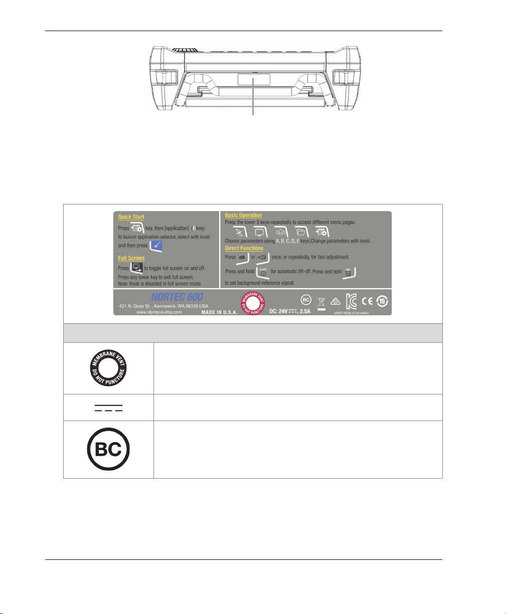
Instruction and rating label (see Table 1 on page 2)
Labels and Symbols
Safety-related labels and symbols are attached to the instrument at the locations
shown in Figure i-1 on page 1. If any or all of the labels or symbols are missing or
illegible, please contact Olympus.
Figure i‑1 Label attached to the back of the instrument
Labels and Symbols 1
Page 12
DMTA-10040-01EN, Rev. E, February 2018
Serial number location (see Table 1 on page 2)
Figure i‑2 Location of the serial number
Table 1 Content of the rating label
This symbol indicates the location of the membrane vent.
The direct current symbol.
Efficiency of battery chargers specific to California, USA.
Labels and Symbols2
Content
Page 13
DMTA-10040-01EN, Rev. E, February 2018
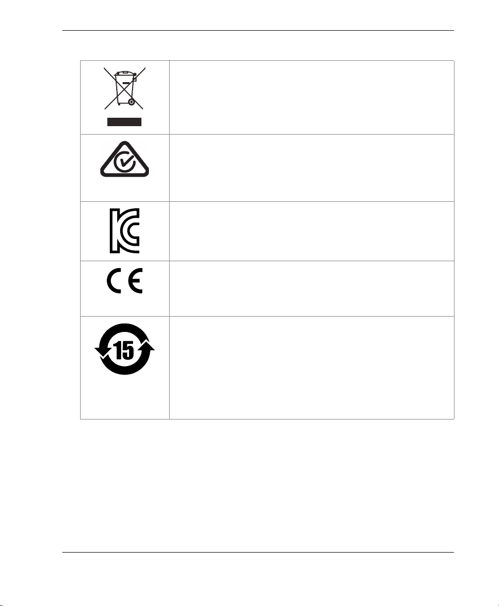
Table 1 Content of the rating label (continued)
The WEEE symbol indicates that the product must not be
disposed of as unsorted municipal waste, but should be
collected separately.
The regulatory compliance mark (RCM) label indicates that
the product complies with all applicable standards, and has
been registered with the Australian Communications and
Media Authority (ACMA) for placement on the Australian
market.
Seller and user shall be noticed that this equipment is suitable
for electromagnetic equipment for office work (class A) and it
can be used outside home. The MSIP code for the
NORTEC 600 is the following: MSIP-REM-OYN-N600.
The CE marking is a declaration that this product conforms to
all the applicable directives of the European Community. See
the Declaration of Conformity for details. Contact your Olympus
representative for more information.
The China RoHS mark indicates the product’s EnvironmentFriendly Use Period (EFUP). The EFUP is defined as the
number of years for which listed controlled substances will not
leak or chemically deteriorate while in the product. The EFUP
for the NORTEC 600 has been determined to be 15 years. Note:
The Environment-Friendly Use Period (EFUP) is not meant to
be interpreted as the period assuring functionality and
product performance.
Labels and Symbols 3
Page 14
DMTA-10040-01EN, Rev. E, February 2018
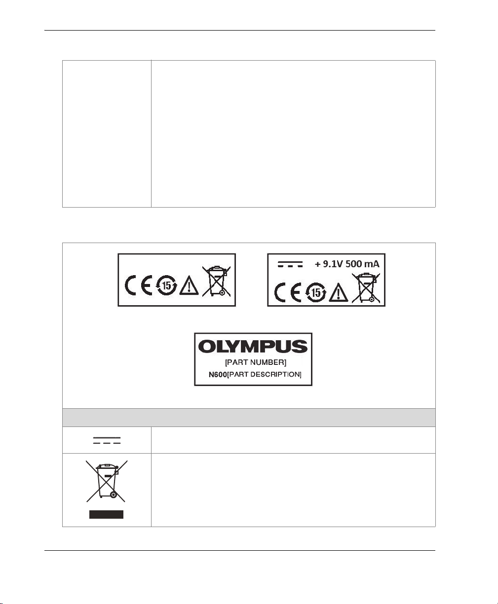
RFT adaptor label
ECT and NFT adaptor label
Part identification label
Table 1 Content of the rating label (continued)
SERIAL The serial number is a nine (9) digit number in the following
format:
yynnnddmm
where:
yy Production year
nnn Unit number manufactured that day
dd Production day
mm Production month
For example, the 130050609 serial number indicates that the
fifth unit (005) was produced on 6 September 2013.
Table 2 Content of the probe adaptor labels
Labels and Symbols4
Content
The direct current symbol.
The WEEE symbol indicates that the product must not be
disposed of as unsorted municipal waste, but should be
collected separately.
Page 15
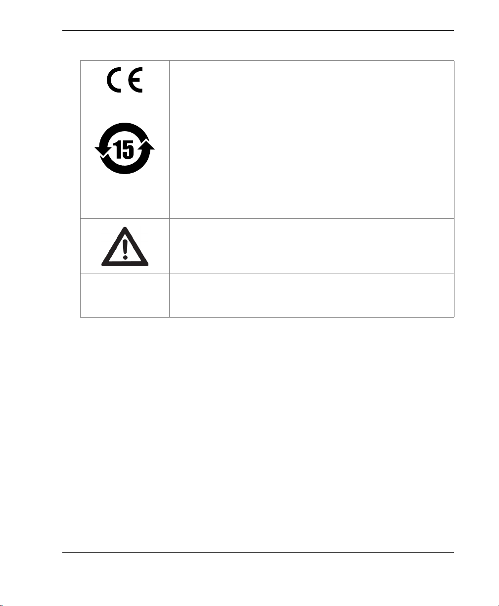
Table 2 Content of the probe adaptor labels (continued)
Part
identification
information
DMTA-10040-01EN, Rev. E, February 2018
The CE marking is a declaration that this product conforms to
all the applicable directives of the European Community. See
the Declaration of Conformity for details. Contact your Olympus
representative for more information.
The China RoHS mark indicates the product’s EnvironmentFriendly Use Period (EFUP). The EFUP is defined as the
number of years for which listed controlled substances will not
leak or chemically deteriorate while in the product. The EFUP
for the NORTEC 600 probe cable has been determined to be
15 years. Note: The Environment-Friendly Use Period (EFUP)
is not meant to be interpreted as the period assuring
functionality and product performance.
The warning symbol indicates that the user must read the
user’s manual in order to find out the nature of the potential
hazards and any actions to avoid them.
The product’s part number and description.
Labels and Symbols 5
Page 16

DMTA-10040-01EN, Rev. E, February 2018
Labels and Symbols6
Page 17
DMTA-10040-01EN, Rev. E, February 2018
WARNING
Important Information — Please Read Before Use
Intended Use
The NORTEC 600 is designed to perform nondestructive inspections on industrial
and commercial materials.
Do not use the NORTEC 600 for any purpose other than its intended use. It must
never be used to inspect or examine human or animal body parts.
Instruction Manual
This instruction manual contains essential information on how to use this Olympus
product safely and effectively. Before using this product, thoroughly review this
instruction manual. Use the product as instructed.
Keep this instruction manual in a safe, accessible location.
Important Information — Please Read Before Use 7
Page 18
DMTA-10040-01EN, Rev. E, February 2018
IMPORTANT
NOTE
CAUTION
Some of the details of components illustrated in this manual may differ from the
components installed on your instrument. However, the operating principles remain
the same.
Instrument Compatibility
Only use the NORTEC 600 instrument with the following ancillary equipment:
• Rechargeable lithium-ion (Li-ion) battery pack (Olympus P/N: 600-BAT-L-2
[U8760058])
• Optional stand-alone external battery charger (Olympus P/N: EPXT-EC-X
[U8767043]), where “X” denotes the power cord type (see Table 12 on page 342).
• Charger/adaptor (Olympus P/N: EP-MCA-X), where “X” denotes the power cord
type (see Table 14 on page 343).
See “Accessories, Replacement Parts, and Upgrades” on page 341 for more details
about accessories.
Always use equipment and accessories that meet Olympus specifications. Using
incompatible equipment could cause equipment malfunction and/or damage, or
human injury.
The following rotating scanners are compatible with the NORTEC 600S and
NORTEC 600D instrument models:
• MiniMite
•Spitfire
Important Information — Please Read Before Use8
Page 19
DMTA-10040-01EN, Rev. E, February 2018
IMPORTANT
CAUTION
• RA-2000 (replaces the RA-19 scanner, which became obsoleted in 2002. The RA-19
scanner is NOT
series)
•PS5
• GE Hocking MiniDrive
• Rohmann Elotest MR3 scanner
ANY other scanner not listed here has not been tested and is NOT supported at the
time of publication of this manual.
compatible with the NORTEC 500 or NORTEC 600 instrument
Repair and Modification
The NORTEC 600 does not contain any user-serviceable parts. Opening the
instrument might void the warranty.
In order to prevent human injury and/or equipment damage, do not disassemble,
modify, or attempt to repair the instrument.
Patent Rights Protection
Certain components of Olympus products are patented. For more details, see the
About > Legal Info menu on the NORTEC 600 instrument display.
Important Information — Please Read Before Use 9
Page 20
DMTA-10040-01EN, Rev. E, February 2018
DANGER
WARNING
Safety Symbols
The following safety symbols might appear on the instrument and in the instruction
manual:
General warning symbol
This symbol is used to alert the user to potential hazards. All safety messages that
follow this symbol shall be obeyed to avoid possible harm or material damage.
Shock hazard caution symbol
This symbol is used to alert the user to potential laser hazards. All safety
messages that follow this symbol shall be obeyed to avoid possible harm or
material damage.
Safety Signal Words
The following safety signal words might appear in the documentation of the
instrument:
The DANGER signal word indicates an imminently hazardous situation. It calls
attention to a procedure, practice, or the like that if not correctly performed or
adhered to will result in death or serious personal injury. Do not proceed beyond a
DANGER signal word until the indicated conditions are fully understood and met.
The WARNING signal word indicates a potentially hazardous situation. It calls
attention to a procedure, practice, or the like that if not correctly performed or
adhered to could result in death or serious personal injury. Do not proceed beyond a
WARNING signal word until the indicated conditions are fully understood and met.
Important Information — Please Read Before Use10
Page 21
DMTA-10040-01EN, Rev. E, February 2018
CAUTION
IMPORTANT
NOTE
TIP
The CAUTION signal word indicates a potentially hazardous situation. It calls
attention to a procedure, practice, or the like that if not correctly performed or
adhered to may result in minor or moderate personal injury, material damage,
particularly to the product, destruction of part or all of the product, or loss of data. Do
not proceed beyond a CAUTION signal word until the indicated conditions are fully
understood and met.
Note Signal Words
The following note signal words could appear in the documentation of the
instrument:
The IMPORTANT signal word calls attention to a note that provides important
information, or information essential to the completion of a task.
The NOTE signal word calls attention to an operating procedure, practice, or the like,
which requires special attention. A note also denotes related parenthetical
information that is useful, but not imperative.
The TIP signal word calls attention to a type of note that helps you apply the
techniques and procedures described in the manual to your specific needs, or
provides hints on how to effectively use the capabilities of the product.
Safety
Before turning on the instrument, verify that the correct safety precautions have been
taken (see the following warnings). In addition, note the external markings on the
instrument, which are described under “Safety Symbols.”
Important Information — Please Read Before Use 11
Page 22
DMTA-10040-01EN, Rev. E, February 2018
WARNING
WARNING
Warnings
General Warnings
• Carefully read the instructions contained in this instruction manual prior to
turning on the instrument.
• Keep this instruction manual in a safe place for further reference.
• Follow the installation and operation procedures.
• It is imperative to respect the safety warnings on the instrument and in this
instruction manual.
• If the equipment is used in a manner not specified by the manufacturer, the
protection provided by the equipment could be impaired.
• Do not install substitute parts or perform any unauthorized modification to the
instrument.
• Service instructions, when applicable, are for trained service personnel. To avoid
the risk of electric shock, do not perform any work on the instrument unless
qualified to do so. For any problem or question regarding this instrument, contact
Olympus or an authorized Olympus representative.
• Do not touch the connectors directly by hand. Otherwise, a malfunction or electric
shock may result.
• Do not allow metallic or foreign objects to enter the device through connectors or
any other openings. Otherwise, a malfunction or electric shock may result.
Electrical Warning
The instrument must only be connected to a power source corresponding to the type
indicated on the rating label.
Important Information — Please Read Before Use12
Page 23
DMTA-10040-01EN, Rev. E, February 2018
CAUTION
CAUTION
If a nonapproved power supply cord not dedicated to Olympus products is used,
Olympus will not be able to ensure the electrical safety of the equipment.
Battery Precautions
• Before disposing of a battery, check your local laws, rules, and regulations, and
follow them accordingly.
• Transportation of lithium-ion batteries is regulated by the United Nations under
the United Nations Recommendations on the Transport of Dangerous Goods. It is
expected that governments, intergovernmental organizations, and other
international organizations shall conform to the principles laid down in these
regulations, thus contributing to worldwide harmonization in this field. These
international organizations include the International Civil Aviation organization
(ICAO), the International Air Transport Association (IATA), the International
Maritime Organization (IMO), the US Department of Transportation (USDOT),
Transport Canada (TC), and others. Please contact the transporter and confirm
current regulations before transportation of lithium-ion batteries.
• Do not open, crush, or perforate batteries; doing so could cause injury.
• Do not incinerate batteries. Keep batteries away from fire and other sources of
extreme heat. Exposing batteries to extreme heat (over 80 °C) could result in an
explosion or personal injury.
• Do not drop, hit, or otherwise abuse a battery, as doing so could expose the cell
contents, which are corrosive and explosive.
• Do not short-circuit the battery terminals. A short circuit could cause injury and
severe damage to a battery making it unusable.
• Do not expose a battery to moisture or rain; doing so could cause an electric
shock.
• Only use the NORTEC 600 unit or an external charger approved by Olympus to
charge the batteries.
• Only use batteries supplied by Olympus.
• Do not store batteries that have less than 40 % remaining charge. Recharge
batteries to between 40 % and 80 % capacity before storing them.
Important Information — Please Read Before Use 13
Page 24
DMTA-10040-01EN, Rev. E, February 2018
IMPORTANT
• During storage, keep the battery charge between 40 % and 80 %.
• Do not leave batteries in the NORTEC 600 unit during instrument storage.
Equipment Disposal
Before disposing of the NORTEC 600, check your local laws, rules, and regulations,
and follow them accordingly.
CE (European Community)
This device complies with the requirements of directive 2014/30/EU
concerning electromagnetic compatibility, directive 2014/35/EU
concerning low voltage, and directive 2011/65/EU concerning
restriction of hazardous substances (RoHS). The CE marking indicates
compliance with the above directives.
Tubing probes (with cables) that are 25 m (82 ft) in length or under are CE compliant
when used with the NORTEC 600 instrument. Probes (with cables) over 25 m (82 ft) in
length are not CE compliant.
WEEE Directive
Important Information — Please Read Before Use14
In accordance with European Directive 2012/19/EU on Waste Electrical
and Electronic Equipment (WEEE), this symbol indicates that the
product must not be disposed of as unsorted municipal waste, but
should be collected separately. Refer to your local Olympus distributor
for return and/or collection systems available in your country.
Page 25
DMTA-10040-01EN, Rev. E, February 2018
China RoHS
China RoHS is the term used by industry generally to describe legislation
implemented by the Ministry of Information Industry (MII) in the People’s Republic
of China for the control of pollution by electronic information products (EIP).
The China RoHS mark indicates the product’s EnvironmentFriendly Use Period (EFUP). The EFUP is defined as the number of
years for which listed controlled substances will not leak or
chemically deteriorate while in the product. The EFUP for the
NORTEC 600 has been determined to be 15 years.
Note: The Environment-Friendly Use Period (EFUP) is not meant
to be interpreted as the period assuring functionality and product
performance.
“ 中国 RoHS” 是一个工业术语,一般用于描述中华人民共和国信息工业部 (MII)针
对控制电子信息产品 (EIP)的污染所实行的法令。
中国 RoHS 标识是根据 “ 电器电子产品有害物质限制使用管理办
法 ” 以及 “ 电子电气产品有害物质限制使用标识要求 ” 的规定,适
用于在中国销售的电气电子产品上的电气电子产品有害物质限制使
用标识。
电气电子产品
有害物质
限制使用标识
注意:电气电子产品有害物质限制使用标识内的数字为在正常的使
用条件下有害物质不会泄漏的年限,不是保证产品功能性的年限。
部件名称 铅及其
机构部件
主体 光学部件
电气部件
产品中有害物质的名称及含量
有害物质
汞及其
化合物
(Pb) (Hg) (Cd)
× ○○○○○
× ○○○○○
× ○○○○○
化合物
镉及其
化合物
六价铬及
其化合物
(Cr( Ⅵ ))
多溴联苯 多溴
二苯醚
(PBB) (PBDE)
Important Information — Please Read Before Use 15
Page 26

DMTA-10040-01EN, Rev. E, February 2018
产品中有害物质的名称及含量
有害物质
部件名称 铅及其
化合物
(Pb) (Hg) (Cd)
附件
本表格依据 SJ/T 11364 的规定编制。
○:表示该有害物质在该部件所有均质材料中的含量均在 GB/T26572 规定的限量要求以下。
×:表示该有害物质至少在该部件的某一均质材料中的含量超出 GB/T26572 规定的限量要求。
× ○○○○○
汞及其
化合物
镉及其
化合物
六价铬及
其化合物
(Cr( Ⅵ ))
多溴联苯 多溴
(PBB) (PBDE)
Korea Communications Commission (KCC)
이 기기는 업무용 환경에서 사용할 목적으로 적합성평가를 받은 기기로서 가정용 환
경에서 사용하는 경우 전파간섭의 우려가 있습니다 .
EMC Directive Compliance
This equipment generates and uses radio-frequency energy and, if not installed and
used properly (that is, in strict accordance with the manufacturer’s instructions), may
cause interference. The NORTEC 600 has been tested and found to comply with the
limits for an industrial device in accordance with the specifications of the EMC
directive.
二苯醚
FCC (USA) Compliance
This device complies with Part 15 of the FCC Rules. Operation is subject to the
following two conditions:
1. This device may not cause harmful interference.
2. This device must accept any interference received, including interference that
may cause undesired operation.
Changes or modifications not expressly approved by the party responsible for
compliance could void the user’s authority to operate the equipment.
Important Information — Please Read Before Use16
Page 27

DMTA-10040-01EN, Rev. E, February 2018
This equipment has been tested and found to comply with the limits for a Class A
digital device, pursuant to Part 15 of the FCC Rules. These limits are designed to
provide reasonable protection against harmful interference when the equipment is
operated in a commercial environment. This equipment generates, uses, and can
radiate radio frequency energy, and if not installed and used in accordance with the
instruction manual, might cause harmful interference to radio communications.
Operation of this equipment in a residential area is likely to cause harmful
interference, in which case you will be required to correct the interference at your own
expense.
ICES-001 (Canada) Compliance
This Class A digital apparatus complies with Canadian ICES-001.
Cet appareil numérique de la classe A est conforme à la norme NMB-001 du Canada.
Warranty Information
Olympus guarantees your Olympus product to be free from defects in materials and
workmanship for a specific period, and in accordance with conditions specified in the
Olympus Scientific Solutions Americas Inc. Terms and Conditions available at
http://www.olympus-ims.com/en/terms/.
The Olympus warranty only covers equipment that has been used in a proper
manner, as described in this instruction manual, and that has not been subjected to
excessive abuse, attempted unauthorized repair, or modification.
Inspect materials thoroughly on receipt for evidence of external or internal damage
that might have occurred during shipment. Immediately notify the carrier making the
delivery of any damage, because the carrier is normally liable for damage during
shipment. Retain packing materials, waybills, and other shipping documentation
needed in order to file a damage claim. After notifying the carrier, contact Olympus
for assistance with the damage claim and equipment replacement, if necessary.
This instruction manual explains the proper operation of your Olympus product. The
information contained herein is intended solely as a teaching aid, and shall not be
used in any particular application without independent testing and/or verification by
the operator or the supervisor. Such independent verification of procedures becomes
increasingly important as the criticality of the application increases. For this reason,
Important Information — Please Read Before Use 17
Page 28

DMTA-10040-01EN, Rev. E, February 2018
Olympus makes no warranty, expressed or implied, that the techniques, examples, or
procedures described herein are consistent with industry standards, nor that they
meet the requirements of any particular application.
Olympus reserves the right to modify any product without incurring the
responsibility for modifying previously manufactured products.
Technical Support
Olympus is firmly committed to providing the highest level of customer service and
product support. If you experience any difficulties when using our product, or if it
fails to operate as described in the documentation, first consult the user’s manual, and
then, if you are still in need of assistance, contact our After-Sales Service. To locate the
nearest service center, visit the Service Centers page at: http://www.olympusims.com.
Important Information — Please Read Before Use18
Page 29
DMTA-10040-01EN, Rev. E, February 2018
Introduction
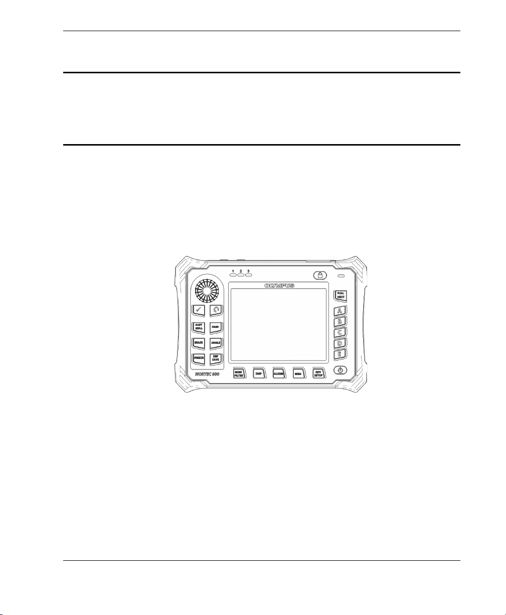
This user’s manual provides operating instructions for the Olympus NORTEC 600
instrument, which uses eddy currents to detect surface flaws in various types of
metals (see Figure i-3 on page 19). The information in this manual is organized to
explain the technology, safety details, hardware, and software. Practical inspection
examples help the user become familiar with the instrument’s capabilities.
Figure i‑3 The NORTEC 600 instrument
Introduction 19
Page 30

DMTA-10040-01EN, Rev. E, February 2018
Introduction20
Page 31

DMTA-10040-01EN, Rev. E, February 2018
1. Instrument Overview
This chapter provides a brief overview of the Olympus NORTEC 600 eddy current
flaw detector, and includes the principle of operation, accessories, and all common
operational requirements.
1.1 Operating Principle
The NORTEC 600 is a small, lightweight flaw detector designed to make fast,
accurate, and repeatable measurements on conductive materials such as aluminum,
copper, stainless steel, steel, and titanium.
The NORTEC 600 uses electromagnetic induction to detect flaws in conductive
materials. Electromagnetic induction is achieved with a coil that carries a current and
that is placed in proximity to the test material. The alternating current in the coil
generates a changing magnetic field that interacts with the test material and causes
eddy currents. Variations in the phase and magnitude of these eddy currents are
monitored. Variations in the electrical conductivity or magnetic permeability of the
test object, or the presence of any flaws, will cause a change in eddy current and a
corresponding change in the phase and amplitude of the measured current.
Eddy current testing can detect very small cracks in or near the surface of non-ferrous
material, and it is also useful for making electrical conductivity and coating thickness
measurements. The surfaces being tested need minimal preparation.
Instrument Overview 21
Page 32

DMTA-10040-01EN, Rev. E, February 2018
1.2 Contents of the Case
The NORTEC 600 comes with several key accessories (see Figure 1-1 on page 23):
• ISO-15548 certificate or calibration certificate (short form of the ISO-15548)
(Olympus P/N: 7922035 [U8030145]).
• Charger/adaptor (Olympus P/N: EP-MCA-X), where “X” denotes the AC power
cord type (see Table 14 on page 343).
• AC power cord
• Getting Started leaflet (Olympus P/N: DMTA-10039-01YY), where “YY” denotes
the language (see Table 17 on page 344 for order numbers).
•NORTEC600 User’s Manual and PC interface program on CD-ROM (Olympus
P/N: N600-CD [U8030151])
• Instrument transport case (P/N: 600-TC [U8780294])
• Universal PowerLink eddy current probe cable (Olympus P/N: 9122083
[U8800073]). Although in some countries this item may be included, for most
countries it is optional and must be purchased separately. Please contact your
Olympus representative for more details.
• microSD memory card 2 GB (1 internal, 1 external) (Olympus P/N: MICROSDADP-2GB [U8779307])
• USB 2.0 (mini-AB) to PC cable (Olympus P/N: EPLTC-C-USB-A-6 [U8840031])
• 73 watt-hour battery for 600 Series products; 10.8 V, 6.8 Ah, 73 Wh (Olympus
P/N: 600-BAT-L-2 [U8760058])
• AA battery holder (tray) for emergency use (Olympus P/N: 600-BAT-AA
[U8780295])
• Factory-installed hand strap on left side of NORTEC 600 instrument
(Olympus P/N: 38DLP-HS [U8779371])
Chapter 122
Page 33

DMTA-10040-01EN, Rev. E, February 2018
Charger/adaptor
AC power cord and
probe cable
Getting Started leaflet and calibration
certificate
NORTEC 600 unit
Transport case (may
differ from your model,
depending on image
available at time of
publication)
User’s manual and PC interface program
on CD-ROM
Li-ion battery
microSD memory card
and USB to PC cable
A list of optional accessories available from Olympus can be found in “Accessories,
Replacement Parts, and Upgrades” on page 341.
1.3 Connectors
Figure 1-2 on page 24 illustrates the connections of the NORTEC 600 instrument with
the charger/adaptor, the microSD card, and a PC.
Figure 1‑1 Transport case contents
Instrument Overview 23
Page 34

DMTA-10040-01EN, Rev. E, February 2018
To po we r
outlet
DC power plug
EP-MCA-X
charger/adaptor
AC power cord
USB to PC
microSD card
WARNING
DC power connector
PROBE connector
(16-pin LEMO)
BNC connector
Figure 1‑2 The NORTEC 600 connections
Use only the AC power cord supplied with your instrument, unless specifically
instructed in the manual. Using an unauthorized power cord may result in damage to
instruments or serious injury to the user.
The DC power, PROBE, and BNC connectors are located on the top end of the
NORTEC 600 (see Figure 1-3 on page 24).
Figure 1‑3 The top end connectors
Chapter 124
Page 35

DMTA-10040-01EN, Rev. E, February 2018
CAUTION
USB port
microSD card slot
I/O door
Removable
microSD card
Do not allow metallic or foreign objects to enter the device through connectors or any
other openings. Otherwise, an electric shock or malfunction may result.
The USB port and the removable microSD memory card slot are located on the righthand side of the instrument, hidden behind the input/output (I/O) door (see
Figure 1-4 on page 25).
Figure 1‑4 The connectors behind the input/output (I/O) door
The I/O and the VGA OUT connectors are located at the back of the instrument, in the
upper section (see Figure 1-5 on page 26). A rubber cover protects each connector.
Instrument Overview 25
Page 36

DMTA-10040-01EN, Rev. E, February 2018
VGA OUT connector
I/O connector
Figure 1‑5 The VGA OUT and I/O connectors
1.4 Power Requirements
The NORTEC 600 is designed to operate using three power supply methods:
• Directly from the NORTEC 600 charger/adaptor
• Internal lithium-ion battery
• Internal alkaline battery holder
Press the power button ( ) to turn on the NORTEC 600 (see Figure 1-6 on page 27).
Pressing this button once causes an initial beep, which is followed by the instrument
startup screen, and then a second beep approximately five seconds later.
Chapter 126
Page 37

DMTA-10040-01EN, Rev. E, February 2018
Charger/adaptor
indicator light
Power button
WARNING
Figure 1‑6 Location of the NORTEC 600 power button and indicator light
1.4.1 Charger/Adaptor
A NORTEC 600 charger/adaptor is provided with every instrument. This
charger/adaptor is the primary method for powering the NORTEC 600, with or
without a battery installed. It is also used to charge the lithium-ion rechargeable
battery when it is installed in the instrument. A charger/adaptor indicator light on the
front panel of the unit displays the current status of the charger/adaptor (see
Figure 1-6 on page 27 and Figure 1-7 on page 27).
Figure 1‑7 The charger/adaptor indicator light on the front panel
Use only the power cord supplied with your instrument, unless specifically instructed
in the manual. Using an unauthorized power cord may result in damage to
instruments or serious injury to the user.
Instrument Overview 27
Page 38

DMTA-10040-01EN, Rev. E, February 2018
WARNING
To power outlet
DC power connector
EP-MCA-X
charger/adaptor
AC power cord
The NORTEC 600 charger/adaptor (P/N: EP-MCA-X) is designed to power the
NORTEC 600 and charge the lithium-ion battery only (P/N: 600-BAT-L-2 [U8760058]).
Do not attempt to charge any other types of batteries, including alkaline batteries in
the battery holder (P/N: 600-BAT-AA [U8780295]), and do not attempt to use any
other charger/adaptor. Doing so might cause an explosion or injury.
Do not attempt to power or charge other electronic equipment with the
charger/adaptor (P/N: EP-MCA-X), unless specifically instructed in the manual.
Misuse of the charger/adaptor can cause other batteries and/or instruments to
explode, which could lead to serious injury or death.
To connect the charger/adaptor
1. Connect the AC power cord to the charger/adaptor and to an appropriate power
outlet (see Figure 1-8 on page 28).
Chapter 128
Figure 1‑8 Connecting the charger/adaptor
Page 39

DMTA-10040-01EN, Rev. E, February 2018
DC power cable from the
charger/adaptor
DC power connector
(rubber seal not shown)
2. Lift the rubber seal that covers the DC connector on top of the NORTEC 600.
3. Connect the DC output power cable from the charger/adaptor to the DC power
connector on top of the NORTEC 600 (see Figure 1-9 on page 29).
Figure 1‑9 Connecting the DC power cable
Table 3 on page 29 explains the indicators for the power status of the charger/adaptor
and the battery charge condition, which are visible at the top of the front panel and in
the user interface.
Table 3 Charger/adaptor and battery indicators
Charger/adaptor
indicator light
Red Yes Internal battery is charging.
Off No Charger/adaptor is not connected.
AC line power
connected
Indicator meaning
Battery
indicator
Instrument Overview 29
Page 40

DMTA-10040-01EN, Rev. E, February 2018
Membrane vent
hole
Thumb screws (two)
Battery compartment
cover
Table 3 Charger/adaptor and battery indicators (continued)
Charger/adaptor
indicator light
Green Yes
AC line power
connected
Indicator meaning
Charger/adaptor is connected, but
no battery is installed.
OR
Internal battery is fully charged.
Battery
indicator
1.4.2 Battery Compartment
The NORTEC 600 battery compartment cover allows you to quickly access the battery
(or AA batteries in the alkaline battery holder) without the need for tools. Two thumb
screws on the battery compartment cover secure it to the instrument case and ensure
the compartment is sealed.
The battery compartment cover also has a small hole in the bottom center area that is
covered on the inside by an environmentally sealed membrane vent. This vent is a
safety feature that is required in the event that the instrument battery fails and emits
gas. This vent must not be punctured.
Figure 1‑10 The battery compartment
Chapter 130
Page 41

DMTA-10040-01EN, Rev. E, February 2018
WARNING
IMPORTANT
The NORTEC 600 accepts one rechargeable lithium-ion battery pack (Olympus
P/N: 600-BAT-L-2 [U8760058]) that can be recharged inside the instrument or on the
optional external charging base (Olympus P/N: EPXT-EC-X [U8767043]). You can also
use the NORTEC 600 with eight standard AA-size alkaline batteries installed in an
alkaline battery holder (Olympus P/N: 600-BAT-AA [U8780295]) for extended
portable use.
If the NORTEC 600 is to be used with a rechargeable battery, only use the Olympus
battery, P/N: 600-BAT-L-2 [U8760058]. Using any other type of battery might cause an
explosion and injury.
1.4.3 Lithium-Ion Battery
The NORTEC 600 is normally used as a portable instrument powered by the lithiumion battery and recharged via the charger/adaptor (both are supplied with the
NORTEC 600). When properly maintained, and when the instrument is operated
under typical inspection conditions, the lithium-ion battery should provide between 8
and 10 hours of continuous operation if a rotating scanner is not connected. If an
Olympus rotating scanner is connected, the NORTEC 600 should provide between 6
and 8 hours of continuous operation.
The lithium-ion battery is not fully charged when the instrument is shipped. You
must charge the battery for two to three hours before using battery power to operate
the instrument (see “Charger/Adaptor” on page 27).
To install or replace the lithium-ion battery
1. Unfold the instrument stand (see Figure 1-11 on page 32).
2. At the back of the instrument, loosen the two thumb screws securing the battery
3. Remove the battery compartment cover.
compartment cover.
Instrument Overview 31
Page 42

DMTA-10040-01EN, Rev. E, February 2018
Battery
compartment
cover
Thumb screws
(two)
Battery
Stand
4. Remove the battery and/or install the new battery in the battery compartment.
5. Check the cover gasket to make sure it is clean and in good condition.
6. Install the battery compartment cover at the back of the instrument, and then
tighten the two thumb screws to complete the installation.
Figure 1‑11 Removing the lithium‑ion battery
1.4.4 Alkaline Batteries
The NORTEC 600 includes a battery holder (Olympus P/N: 600-BAT-AA [U8780295]).
This holder accommodates eight AA-size alkaline batteries for situations where an
AC power source is not available and the internal Li-ion battery is discharged. When
operated under typical inspection conditions, the alkaline batteries typically provide
three hours of continuous operation.
To install the alkaline battery holder
1. Unfold the instrument stand (see Figure 1-12 on page 33).
2. Loosen the two thumb screws securing the battery compartment cover at the back
of the instrument, and then remove the battery compartment cover.
3. Remove the lithium-ion battery, if installed.
4. Install eight AA-size alkaline batteries into the alkaline battery holder.
5. Connect the alkaline battery holder connector to the instrument.
Chapter 132
Page 43

DMTA-10040-01EN, Rev. E, February 2018
Battery holder
with alkaline
batteries (eight)
Battery holder
connector
Battery compartment cover
Thumb screws
(two)
Stand
NOTE
6. Position the alkaline battery holder in the battery compartment.
Figure 1‑12 The alkaline battery holder
7. Install the battery compartment cover at the back of the instrument, and then
tighten the two thumb screws.
When alkaline batteries are installed in the instrument, the battery indicator in the
user interface displays ALK. The charger/adaptor does not recharge the batteries
installed in the alkaline battery holder.
1.5 Optional microSD Card Installation
A 2 GB microSD card (Olympus P/N: MICROSD-ADP-2GB [U8779307]) can be
installed in the NORTEC 600 instrument.
To install the microSD removable memory card
1. Remove the card from its packaging.
Instrument Overview 33
Page 44

DMTA-10040-01EN, Rev. E, February 2018
USB port
Thumb screws (two)
microSD card slot
microSD card
NOTE
2. Loosen the two thumb screws, and then open the NORTEC 600 I/O door (see
Figure 1-13 on page 34).
Figure 1‑13 Installing the microSD card
3. Hold the card so that the microSD label faces toward the rear of the instrument.
4. Gently slide the card into the microSD slot until it clicks.
To remove the microSD card, gently push the card into the instrument and release. A
spring-loaded mechanism will partially eject the card, and then you can grasp the
card and remove it from the instrument.
1.6 NORTEC 600 Hardware Features
The NORTEC 600 instrument has many physical features that are either completely
new or improvements of features on older NORTEC 500 models. It is important to
become familiar with the use and maintenance of these items.
Chapter 134
Page 45

DMTA-10040-01EN, Rev. E, February 2018
Protective rubber bumpers
D-rings to attach the
optional chest harness
(at the four corners)
Display window
(screen)
Keypad
Knob (SmartKnob)
1.6.1 Hardware Overview
Figure 1-14 on page 35 and Figure 1-15 on page 36 show the main components on the
NORTEC 600 instrument.
Figure 1‑14 Overview of the NORTEC 600 hardware — Front view
Instrument Overview 35
Page 46

DMTA-10040-01EN, Rev. E, February 2018
DC power connector
VGA OUT connector
Stand
Battery compartment
cover
BNC connector
PROBE connector
Membrane vent
I/O door
I/O connector
Figure 1‑15 Overview of the NORTEC 600 hardware — Back view
1.6.1.1 Front Panel and SmartKnob
The SmartKnob is an important feature of the NORTEC 600 instrument, and it is the
primary method used to change different parameters within a menu. In this manual,
the term “knob” is also used to refer to the SmartKnob.
The NORTEC 600 front panel features direct-function keys that are used in
combination with the SmartKnob to provide direct access to menus and common
parameters, and to enable easy adjustment of values (see Figure 1-16 on page 37).
Chapter 136
Page 47

DMTA-10040-01EN, Rev. E, February 2018
Direct-function
keys
Function keys
Charger/adaptor
indicator
Power button
Display window (screen)
SmartKnob
Menu keys
FULL NEXT key
Figure 1‑16 The NORTEC 600 front panel with SmartKnob and keypad
1.6.1.2 Keypad
The NORTEC 600 is available with an English, Chinese, Japanese, or international
keypad configuration (see Figure 1-17 on page 38 to Figure 1-20 on page 39, and
Table 4 on page 40). The text labels on some keys may be replaced by pictograms,
depending on the keypad configuration. In this document, keys are referred to using
the English label, which indicates its function. The keys are used to select menu items
or screen parameters and to change parameter values.
Instrument Overview 37
Page 48

DMTA-10040-01EN, Rev. E, February 2018
Figure 1‑17 The NORTEC 600 English keypad
Figure 1‑18 The NORTEC 600 Chinese keypad
Chapter 138
Page 49

DMTA-10040-01EN, Rev. E, February 2018
Figure 1‑19 The NORTEC 600 Japanese keypad
Figure 1‑20 The NORTEC 600 international keypad
Instrument Overview 39
Page 50

DMTA-10040-01EN, Rev. E, February 2018
Table 4 Keypad functions
Function
name
International
keypad
symbol
Function description
Enter The Enter key is used to make selections.
Return The Return (or Back) key is used to exit a
menu and return to a previous screen.
A-LIFT NULL If this direct-function key is pressed once, it
nulls (zeros) the instrument. If this key is
pressed and held, the Auto Liftoff is set.
GAIN Direct-function key used to display either
the instrument’s combined horizontal and
vertical gain settings, horizontal gain only,
or vertical gain only.
ERASE Direct-function key used to erase the
currently displayed image.
ANGLE Direct-function key used to display the
angle.
FREEZE Direct-function key used to freeze the
image displayed on the instrument for
further evaluation. When the image is
frozen, the NORTEC 600 also allows
calibrating the eddy current signals, and
changing the gains or angle.
REF SAVE Direct-function key used to save images
and settings in the instrument’s memory.
When this key is pressed once (and
released), the currently displayed image
and settings are saved. When this key is
pressed and held, the current instrument
image is set as the reference memory
display.
Chapter 140
Page 51

DMTA-10040-01EN, Rev. E, February 2018
Table 4 Keypad functions (continued)
Function
name
International
keypad
symbol
Function description
MAIN FILTER Provides access to the main menu, which
controls functions such as frequency, gain,
angle, and filters.
DISP Provides access to the display menu, which
controls functions such as display mode,
position, trace, and grid.
ALARM Provides access to the alarm menu, which
controls functions such as alarm type,
dwell time, horn volume, and alarm
position.
MEM Provides access to the memory menu,
which controls functions such as
previewing stored memory files, recalling
and editing stored files, capture mode,
capture time, and user information.
ADV SETUP Provides access to the instrument’s
advanced settings, including the
application selection menu, the ALL
SETTINGS menu, frequency mode, colors,
password, systems setup, reset, unlock
options, and legal/regulatory information.
FULL NEXT Used to expand the instrument display to
full screen, or to select items in the menu.
A A Function key
B B Function key
C C Function key
D D Function key
E E Function key
Instrument Overview 41
Page 52

DMTA-10040-01EN, Rev. E, February 2018
BNC connector
PROBE connector
CAUTION
1.6.2 Connectors
The NORTEC 600 instrument contains several types of connectors for hardware
components.
1.6.2.1 Probe and BNC Connectors
The NORTEC 600 instrument is supplied with a 16-pin LEMO (PROBE) connector
and a BNC connector.
The PROBE (LEMO) and BNC connectors are located at the top of the instrument, on
the left-hand side. The two connectors are easily accessible from the front of the
instrument (see Figure 1-21 on page 42).
Figure 1‑21 Location of the PROBE (LEMO) and BNC connectors
Do not allow metallic or foreign objects to enter the device through connectors or any
other openings. Otherwise, an electric shock or malfunction may result.
1.6.2.2 Input/Output (I/O) and VGA OUT Connectors
The I/O and the VGA OUT connectors are located at the back of the instrument, in the
upper section (see Figure 1-22 on page 43). A rubber cover protects each connector.
Chapter 142
Page 53

DMTA-10040-01EN, Rev. E, February 2018
VGA OUT connector
I/O connector
CAUTION
Figure 1‑22 The VGA OUT and I/O connectors
The VGA OUT connector allows the user to connect the instrument to a standard
analog computer monitor. The I/O connector is used to connect an external horn or, if
necessary, to connect an external control for integrating the NORTEC 600 into a
system. For PC communication details, see “microSD and USB Port” on page 44.
Do not expose the instrument to harsh and wet environments while the I/O or the
VGA OUT connectors are not protected by their rubber covers. To prevent connector
corrosion and damage to the instrument, keep the rubber protective covers on the
connectors when no cable is connected.
Instrument Overview 43
Page 54

DMTA-10040-01EN, Rev. E, February 2018
USB port
Thumb screws (two)
microSD card slot
1.6.2.3 microSD and USB Port
On the right-hand side of the NORTEC 600, a door covers the microSD slot and the
USB port (see Figure 1-23 on page 44). The I/O door closes against an integral
membrane seal to keep liquids away from the unsealed connectors behind the door.
The NORTEC 600 utilizes 2 GB microSD memory cards for both onboard and
removable memory. The onboard 2 GB microSD card is mounted on the PC board
inside the instrument, and is responsible for all onboard data storage. In the event the
instrument is damaged beyond repair, this microSD card can be removed at an
authorized service center, allowing you to recover critical data from the damaged
instrument.
The NORTEC 600 allows the user to connect the instrument to a PC via the USB port.
PC communication requires the interface program (Olympus P/N: N600-CD
[U8030151]) provided with the instrument for file transfers. The NORTEC 600 can
also communicate directly with other SPC programs.
The I/O door is kept closed by two thumb screws. You can also use a coin or a
screwdriver to manipulate these thumb screws as needed.
Chapter 144
Figure 1‑23 The microSD slot and USB port
Page 55

DMTA-10040-01EN, Rev. E, February 2018
CAUTION
Do not expose the instrument to harsh and wet environments while the I/O door is
open. To prevent connector corrosion and damage to the instrument, keep the I/O
door closed and sealed when no cable is connected.
1.6.3 Various Hardware Features
The NORTEC 600 instrument’s physical features make it suitable for a variety of
operating environments.
1.6.3.1 Instrument Stand
The NORTEC 600 features an articulating stand for variable viewing angles (see
Figure 1-24 on page 45). The stand is attached to the back of the instrument with two
hard pivot blocks. There is a high-friction coating on the stand surface to help prevent
it from sliding. The stand is bent in the center to easily accommodate being placed on
a curved surface.
Figure 1‑24 Instrument stand
Instrument Overview 45
Page 56

DMTA-10040-01EN, Rev. E, February 2018
CAUTION
1.6.3.2 O-Ring Gasket and Membrane Seals
The NORTEC 600 contains seals that protect the instrument’s internal hardware from
the environment:
• Battery compartment cover seal
• I/O door seal
• Membrane vent
These seals must be properly maintained to assure environmental durability.
Instrument seals are evaluated and replaced as needed during the instrument annual
calibration. This should be performed at an authorized Olympus service center.
1.6.3.3 Display Protection
The NORTEC 600 includes a clear plastic sheet protecting the instrument display
window. Olympus strongly recommends leaving this protection sheet in place.
Replacements are available in packages of ten sheets (Olympus P/N: 600-DP
[U8780297]).
The display window is permanently bonded to the instrument case to fully seal the
instrument. If the display window becomes damaged, the front part of the case must
be replaced, along with the instrument’s keypad.
1.6.4 Environmental Ratings
The NORTEC 600 is an extremely rugged and durable instrument that can be used in
harsh environments. To classify the instrument’s durability in wet or damp
environments, Olympus has adopted the IP (ingress protection) system to rate how
well the instrument is sealed.
The NORTEC 600 is designed and manufactured to meet the requirements of the IP66
ingress protection rating. To maintain this level of protection, you are responsible for
the proper care of all routinely exposed membrane seals. Additionally, you are
responsible for returning the instrument to an authorized Olympus service center
each year to ensure that the instrument seals are properly maintained. Olympus
Chapter 146
Page 57

DMTA-10040-01EN, Rev. E, February 2018
cannot guarantee any level of ingress protection performance once the instrument
seals have been manipulated. You must use sound judgment and take proper
precautions before exposing the instrument to harsh environments.
The NORTEC 600 adheres to the environmental standards listed in Table 8 on
page 333.
Instrument Overview 47
Page 58

DMTA-10040-01EN, Rev. E, February 2018
Chapter 148
Page 59

DMTA-10040-01EN, Rev. E, February 2018
2. Software User Interface
This chapter explains the main software screens and menus on the NORTEC 600
instrument. The back of the NORTEC 600 contains a quick guide to the instrument
keypad and functions (see Figure 2-1 on page 49).
Figure 2‑1 The instrument label showing keypad functions
2.1 Starting Up the Instrument
When power is turned on, the NORTEC 600 starts up in one of two modes, depending
on what is connected to the instrument.
If no probe is connected, or if a probe that is not a PowerLink type of probe is
connected, the first screen displayed by the NORTEC 600 software is the application
quick-setup menu (see Figure 2-2 on page 50). Choose from among the basic
applications on this menu to automatically configure the appropriate instruments
settings. For more details on the application quick-setup menu, see “Common
NORTEC 600 Applications” on page 120.
Software User Interface 49
Page 60

DMTA-10040-01EN, Rev. E, February 2018
NOTE
Figure 2‑2 Application choices on the quick‑setup menu
The NORTEC 600 applications are designed for quick setup of the instrument.
However, always follow published maintenance procedures when inspecting.
2.1.1 Navigating the Application Menu
Navigating the menu is designed to be intuitive, and the settings for each application
will permit immediate inspection; little or no additional instrument setup is needed.
To navigate the application menu
1. Rotate the knob to highlight one of the eight applications.
2. Press the Enter key ( ) to select the application.
OR
Press the Return key ( ) to go back to the NORTEC 600 main screen.
Alternatively, if a PowerLink probe is connected to the instrument when it is turned
on, the NORTEC 600 starts up in the PowerLink recognition screen (see Figure 2-3 on
page 51).
Chapter 250
Page 61

DMTA-10040-01EN, Rev. E, February 2018
Figure 2‑3 The PowerLink recognition screen
To navigate the application menu for PowerLink
In the PowerLink recognition screen, load the program stored in the PowerLink
probe by pressing the A key.
You can use the KEEP LAST SETTINGS function to load the previous
parameters if they are compatible with the probe or accessory that is detected.
This automatically sets up the instrument.
OR
Bypass the stored program in the probe and gain access to the instrument’s main
inspection screen by pressing the Return key ( ).
2.1.2 Main Inspection Screen
After the initial steps are completed through the quick-setup menu or PowerLink
menu, the main inspection screen is displayed (see Figure 2-4 on page 52).
Software User Interface 51
Page 62

DMTA-10040-01EN, Rev. E, February 2018
Figure 2‑4 The main inspection screen
The battery power indicator remains visible at the top of the screen, except when in
full-screen mode (see Table 3 on page 29 for details). The time and date also remain
visible, except when in full-screen mode.
The rectangular readout in the top-left corner of the screen is called the quick-access
bar (see Figure 2-5 on page 53). It displays either the instrument combined horizontal
and vertical gain settings, horizontal gain only, vertical gain only, or angle setting
when the GAIN ( ) or ANGLE ( ) direct-function keys are pressed. The
quick-access bar remains visible until any other key is pressed.
Chapter 252
Page 63

DMTA-10040-01EN, Rev. E, February 2018
Direct-function
keys
Function keys
Real-time readings bar
Menu keys
Quick-access bar
Operation menu
(instrument settings)
FULL NEXT key
Figure 2‑5 The NORTEC 600 front panel and main inspection screen
The real-time readings bar displays user-configurable readings (measurements) [see
Figure 2-5 on page 53]. It can display a maximum of two real-time readings from
among the available choices. The real-time readings bar can be set to display one or
two readings, or it can be disabled. For more information, see “Displaying Real-Time
Readings” on page 56.
The instrument settings are displayed on the right hand side of the main screen. The
displayed settings information can change, depending on the menu key that is
pressed. The menu keys are the five keys located at the bottom of the front panel:
MAIN FILTER ( ), DISP ( ), ALARM ( ), MEM ( ), and ADV SETUP
( ), as shown in Figure 2-5 on page 53.
The microSD memory card can be inserted into a slot that is located behind the I/O
door on the right-hand side of the instrument (see Figure 1-23 on page 44). Depending
on the context and on the available functions and options, various indicators and
numeric values appear on the screen and around the main measurement value (see
Figure 2-5 on page 53).
Software User Interface 53
Page 64

DMTA-10040-01EN, Rev. E, February 2018
2.2 Selecting from the Menus
The NORTEC 600 menu keys at the bottom of the front panel are MAIN FILTER
( ), DISP ( ), ALARM ( ), MEM ( ), and ADV SETUP ( ). These
keys provide access to the operation menu. This menu appears at the right-hand side
of the screen (see Figure 2-5 on page 53). If applicable, pressing a menu key again will
display a secondary menu with parameters available for that key.
To select from a menu
1. Press one of the menu keys located at the bottom of the front panel to display a
menu: MAIN FILTER ( ), DISP ( ), ALARM ( ), MEM ( ), or
ADV SETUP ( ).
Pressing the same menu key again will cycle through the available options and
update the available functions which can then be adjusted.
2. Select the function to be changed by pressing the function key (A, B, C, D, or E)
located next to the function, which highlights the selected function.
Rotating the knob changes the function‘s value. The value selected with the knob
is automatically entered.
2.3 Displaying All Functions Simultaneously — ALL SETTINGS Menu
As an alternative to the operation menu, the NORTEC 600 has the option of
displaying all functions simultaneously using the ALL SETTINGS menu. The ALL
SETTINGS menu consists of three main elements: the title bar, the parameters, and
the help text (see Figure 2-6 on page 55).
Chapter 254
Page 65

DMTA-10040-01EN, Rev. E, February 2018
Parameters
Title bar
Help text
Figure 2‑6 The ALL SETTINGS menu
2.3.1 Using the ALL SETTINGS Menu
The ALL SETTINGS menu is accessed through the ADV SETUP menu key ( ).
To use the ALL SETTINGS menu
1. Press the ADV SETUP menu key ( ).
2. Press the B key.
3. Press the FULL NEXT key ( ) to select the parameter to be adjusted.
4. Rotate the knob to select the desired value.
5. Press the FULL NEXT key ( ) to select additional parameters to be adjusted.
OR
Press to exit the menu and return to the previous screen.
Software User Interface 55
Page 66

DMTA-10040-01EN, Rev. E, February 2018
NOTE
NOTE
Because of the large number of functions that are available on the NORTEC 600
instrument, the ALL SETTINGS menu contains multiple screens, or pages. The help
text at the bottom of the menu provides any additional navigation options that may
be needed.
2.3.2 Special Functions in the ALL SETTINGS Menu
Two special instrument functions are found only in the ALL SETTINGS menu:
EXT HORN (external horn) and AOUT PWR (analog out power). These functions
control the power or enable the output connectors on the back of the instrument
(see Figure 1-22 on page 43). To enable these functions, follow the instructions in
“Using the ALL SETTINGS Menu” on page 55.
If the NORTEC 600 instrument is being used in noisy conditions, an external horn can
be used. The horn connects to the I/O connector on the back of the instrument and
increases the audible alarm’s sound output to 70 dB (see Table 12 on page 342 for the
part specification).
2.4 Displaying Real-Time Readings
The real-time readings bar displays user-configurable readings (measurements) [see
Figure 2-5 on page 53]. It can display a maximum of two real-time readings from
among seven available choices. The real-time readings bar can be set to display one or
two readings, or it can be disabled.
The following readings can be displayed (see Figure 2-7 on page 57 through
Figure 2-11 on page 59):
• OFF
• APP — Maximum amplitude vector, peak-to-peak (P-P)
• VPP — Maximum vertical voltage, peak-to-peak
Chapter 256
Page 67

DMTA-10040-01EN, Rev. E, February 2018
Volts P-P
and
Angle P-P
Volts P-P Horz.
• HPP — Maximum horizontal voltage, peak-to-peak
• VMAX — Maximum vertical voltage from extended null line
• HMAX — Maximum horizontal voltage from extended null line
• DEG PP — Angle of VMAX, peak-to-peak
Figure 2‑7 Example of VPP and DEG PP
Figure 2‑8 Example of HPP
Software User Interface 57
Page 68

DMTA-10040-01EN, Rev. E, February 2018
Volts P-P
Vert.
Volts Max Horz.
(+ or −)
Figure 2‑9 Example of VPP
Figure 2‑10 Example of HMAX
Chapter 258
Page 69

DMTA-10040-01EN, Rev. E, February 2018
Volts Max Vert.
(+ or −)
NOTE
Figure 2‑11 Example of VMAX
2.4.1 Enabling Real-Time Readings on the Main Inspection Screen
The real-time readings are enabled through the ADV SETUP menu key ( ).
To enable the real-time readings bar on the main inspection screen
1. Press the ADV SETUP menu key ( ).
2. Press the B key.
3. Press the E key.
4. Press the B key.
5. Press the FULL NEXT key ( ) to navigate to the desired type and/or location.
Only TOP LEFT and TOP RIGHT are valid locations for the real-time readings on the
main inspection screen. For available locations in full screen, see “Enabling the RealTime Readings in Full-Screen Mode — FULL NEXT key” on page 60.
6. Rotate the knob to make a selection.
7. Press the FULL NEXT key ( ) to navigate to another type and/or location.
Software User Interface 59
Page 70

DMTA-10040-01EN, Rev. E, February 2018
NOTE
OR
Press the Return key ( ) to exit.
2.4.2 Enabling the Real-Time Readings in Full-Screen Mode — FULL NEXT key
The real-time readings are also available in full-screen mode, which can be accessed
using the FULL NEXT key ( ) shown in Figure 2-5 on page 53. The location of
displayed readings on full screen differs from the location on the main inspection
screen, and readings are user-selectable.
Valid (possible) locations for the real-time readings in full-screen mode are: TOP
LEFT, TOP CNTR (top center), TOP RIGHT, BOT LEFT (bottom left), BOT CNTR
(bottom center) or BOT RGHT (bottom right).
The performance and results of the real-time readings are greatly affected by the
DERASE (display erase) and PERSIST (persistence) settings. It is recommended to
experiment with these parameters. For details on making changes to these settings,
see “D ERASE (display erase)” on page 89 and “PERSIST (variable persistence)” on
page 89.
To enable the real-time readings in full-screen mode (FULL NEXT key)
1. Press the ADV SETUP menu key ( ).
2. Press the B key.
3. Press the E key.
4. Press the B key.
5. Press the FULL NEXT key ( ) to navigate to the desired type and/or location.
6. Rotate the knob to make a selection.
7. Press the FULL NEXT key ( ) to navigate to another type and/or location.
OR
Chapter 260
Page 71

Press the Return key ( ) to exit.
DMTA-10040-01EN, Rev. E, February 2018
Software User Interface 61
Page 72

DMTA-10040-01EN, Rev. E, February 2018
Chapter 262
Page 73

DMTA-10040-01EN, Rev. E, February 2018
3. Initial Setup
This chapter contains the basic configurations for the NORTEC 600 instrument.
3.1 Setting the User Interface Language and the Decimal Symbol
You can configure the NORTEC 600 instrument to present the user interface in the
following languages: English, French, Spanish, German, Japanese, Chinese, Russian,
Swedish, Italian, Portuguese, Norwegian, Hungarian, Polish, Dutch, and Czech. You
can also change the character that represents the decimal of a number.
To change the user interface language and the decimal symbol
1. Press the ADV SETUP menu key ( ) twice, and then press the B key to access
the SYSTEM SETUP screen (see Figure 3-1 on page 63).
Figure 3‑1 The SYSTEM SETUP screen
Initial Setup 63
Page 74

DMTA-10040-01EN, Rev. E, February 2018
2. In the SYSTEM SETUP screen, press the FULL NEXT key ( ) until
LANGUAGE is highlighted.
3. Using the knob, select the desired language.
4. Repeatedly press the FULL NEXT key ( ) until RADIX is highlighted.
5. Using the knob, select the desired character to represent the decimal of numbers:
PERIOD (.) or COMMA (,).
6. Press to return to the previous screen.
3.2 Setting the Clock
The NORTEC 600 has a built-in date and time clock. You can set the date and the time,
and select their respective format. The NORTEC 600 saves all inspection results with
their acquisition date.
To set the clock
1. Press the ADV SETUP menu key ( ) twice, and then press the B key to access
the SYSTEM SETUP screen (see Figure 3-1 on page 63).
2. Set the YEAR, MONTH, DAY, MODE (12 HOUR or 24 HOUR), HOUR,
MINUTE, and DATE MODE as follows:
a) Repeatedly press the FULL NEXT key ( ) until the item (YEAR, MONTH,
DAY, etc.) is highlighted.
b) Rotate the knob until the correct value is displayed.
3. Press to return to the previous screen.
3.3 Changing the Location of Saved Files
Files can be saved on the internal or external (accessible) microSD card.
Chapter 364
Page 75

DMTA-10040-01EN, Rev. E, February 2018
NOTE
To change the location of saved files
1. Press the ADV SETUP menu key ( ) twice, and then press the B key to access
the SYSTEM SETUP screen (see Figure 3-1 on page 63).
2. Repeatedly press the FULL NEXT key ( ) until FILE SAVE LOCATION is
highlighted.
3. Change the location as required; for example, select EXTERNAL if you want to
save files on the external microSD card.
The BACKUP / RESTORE function is disabled when files are saved on the external
microSD card.
3.4 Changing the Display Settings
You can change the appearance of some display elements such as brightness, auto
erase, VGA output, and whether or not the application window displays at startup.
To change the display settings
1. Press the ADV SETUP menu key ( ) twice.
2. Press the B key to access the SYSTEM SETUP screen.
3. In the SYSTEMS SETUP screen (see Figure 3-1 on page 63), use the FULL NEXT
key ( ) to highlight the desired parameter and then use the knob to change its
value:
a) Set BRIGHTNESS to one of the predefined brightness levels: 0%, 25 %, 50 %,
75 %, or 100 % (see “Changing the Display Brightness” on page 66 for
details).
b) Set VGA OUTPUT to ON or OFF.
Initial Setup 65
Page 76

DMTA-10040-01EN, Rev. E, February 2018
NOTE
An external display can be used if the VGA OUTPUT is set to ON, which enables the
VGA output connector on the back of the NORTEC 600 instrument. By default, this
setting is OFF.
c) Set AUTO ERASE to ON or OFF (see “Adjusting Auto Erase” on page 67 for
details).
d) Set APPLICATION WINDOW AT STARTUP to ON or OFF (see “Selecting
the Startup Screen” on page 67 for details).
e) Set CROSSHAIRS to ON or OFF.
If ON is selected, a cross mark, centered on the null position, or point, is
displayed. This is useful for monitoring signal drift from the null point.
4. Press to return to the previous screen.
3.5 Changing the Display Brightness
You can adjust the NORTEC 600 display brightness by changing the backlight
intensity. The display brightness can be set at 0 %, 25 %, 50 %, 75 %, and 100 %.
Choosing a high percentage increases the brightness of the display. By default, the
display brightness is set to 100 %. The NORTEC 600 uses a transflective color display
that reflects ambient light and becomes brighter in direct light. With brighter ambient
conditions, you can set the display BRIGHTNESS to a lower percentage.
To change the display brightness
1. Press the ADV SETUP menu key ( ) twice, then press the B key to enter the
SYSTEM SETUP screen.
2. Repeatedly press the FULL NEXT key ( ) until BRIGHTNESS is highlighted.
3. Using the knob, select the desired BRIGHTNESS percentage: 0%, 25 %, 50 %,
75 %, or 100 %.
4. Press to return to the main inspection screen.
Chapter 366
Page 77

DMTA-10040-01EN, Rev. E, February 2018
NOTE
Reducing the display BRIGHTNESS percentage increases the battery life. Battery life
specifications are based on backlight BRIGHTNESS set to 50 %.
3.6 Adjusting Auto Erase
You can adjust the NORTEC 600 to clear (erase) the screen contents automatically
after the NULL key is pressed. By default, the AUTO ERASE function is set to ON,
but it can be disabled by selecting OFF.
To adjust Auto Erase
1. Press the ADV SETUP menu key ( ) twice, then press the B key to enter the
SYSTEM SETUP screen.
2. Repeatedly press the FULL NEXT key ( ) until AUTO ERASE is highlighted.
3. Use the knob to disable the function (select OFF) or enable the function (select
ON).
4. Press to return to the previous screen.
3.7 Selecting the Startup Screen
You can adjust the NORTEC 600 to display the APPLICATION SELECTION screen
automatically after it is turned on. This function can also be disabled, so that the
instrument will instead display the main inspection screen. By default, the
APPLICATION WINDOW AT STARTUP function is set to ON.
To select the startup screen
1. Press the ADV SETUP menu key ( ) twice, then press the B key to enter the
SYSTEM SETUP screen.
Initial Setup 67
Page 78

DMTA-10040-01EN, Rev. E, February 2018
2. Repeatedly press the FULL NEXT key ( ) until APPLICATION WINDOW AT
STARTUP is highlighted.
3. Use the knob to disable the function (select OFF) or enable the function (select
ON).
4. Press to return to the main inspection screen.
3.8 Enabling Knobless Entry for Harsh Environments
The knobless function allows the NORTEC 600 to be used in radioactive or harsh
environments where the instrument has to be put inside a bag, which makes it
difficult to use the knob.
If the knobless entry function is enabled, the frequency, angle, and the combined
horizontal and vertical gain settings can be increased or decreased using keypad
entries instead of the knob. The knobless entry function is enabled using the SYSTEM
SETUP menu. By default, the knobless entry function is set to OFF. For more
information on knobless entry, see “Knobless Entry” on page 78.
To enable the knobless entry function
1. Press the ADV SETUP menu key ( ) twice, then press the B key to enter the
SYSTEM SETUP screen.
2. Repeatedly press the FULL NEXT key ( ) until KNOBLESS is highlighted.
3. Use the knob to disable the function (select OFF) or enable the function (select
ON).
4. Press to return to the previous screen.
Chapter 368
Page 79

DMTA-10040-01EN, Rev. E, February 2018
4. Control Functions
This chapter provides explanations of the NORTEC 600 instrument control functions.
4.1 PowerLink
The PowerLink feature enables the NORTEC 600 eddy current instrument to
automatically recognize Olympus PowerLink probes and rotating scanners when they
are connected to the instrument. The instrument is then configured according to the
parameters programmed into the PowerLink ID chip. Each PowerLink probe is
programmed at the factory to identify itself based on the model number, preselected
operating frequency, gain, and serial number.
When a PowerLink probe or rotating scanner is connected, the instrument displays
the PowerLink recognition screen (see Figure 4-1 on page 69).
Figure 4‑1 The PowerLink recognition screen
Control Functions 69
Page 80

DMTA-10040-01EN, Rev. E, February 2018
Direct-function
keys
Function keys
Charger/adaptor
indicator
Power button
Display window (screen)
Knob
Menu keys
Lock button
FULL NEXT key
At this point, if the PowerLink function has been enabled, the settings from the probe
or rotating scanner will be loaded into the NORTEC 600 instrument. If the PowerLink
function has been disabled, this screen will be bypassed. In either case, the instrument
will next proceed to the main inspection screen.
If you turn on the instrument with a connected PowerLink probe or rotating scanner,
press the A key to use the PowerLink feature, or press to proceed without using
the PowerLink feature. The KEEP LAST SETTINGS function lets you load the
previous parameters if they are compatible with the probe or accessory that is
detected.
4.2 Instrument Controls
The NORTEC 600 instrument controls are displayed in Figure 4-2 on page 70.
Chapter 470
Figure 4‑2 The NORTEC 600 instrument controls
Page 81

DMTA-10040-01EN, Rev. E, February 2018
NOTE
4.2.1 Display
The NORTEC 600 instrument is configured with a color liquid crystal display (LCD)
and offers 640 × 480 resolution (full VGA). The LCD display, also referred to as a
screen, shows the eddy current signal, menus, status bar, messages, and full screen
text when required. Several display modes are available (see “Display Menu — DISP
Key” on page 87).
4.2.2 Power and Lock Buttons
The power button ( ) toggles the instrument power on and off. At startup, the
instrument will normally attempt to restore its last configuration.
The instrument lock can be enabled or disabled by pressing the lock button ( ).
When activated, the lock disables most of the instrument function keys, menu keys,
and the knob. This prevents inadvertent key entries after the instrument is calibrated
and ready to proceed with inspections.
When the lock is activated, an indicator light ( ) illuminates below the battery life
indicator at the upper right side of the instrument screen, and only the NULL, ERASE
( ), and ANGLE ( ) direct-function keys remain functional.
When the instrument lock is enabled, the knob is available after the ANGLE direct-
function key ( ) is pressed.
4.2.3 Direct-Function Keys
The direct-function keys located on the left side of the instrument are used to directly
select the instrument settings that are most often used for adjustment. Three of the
direct-function keys—A-LIFT NULL ( ), FREEZE ( ), and REF SAVE ( )—have
more than one main function.
Control Functions 71
Page 82

DMTA-10040-01EN, Rev. E, February 2018
NOTE
NOTE
A-LIFT NULL ( )
The primary function of the A-LIFT NULL key ( ) is to “null”, or initialize to
zero, the instrument screen. The secondary function of this key is to enable the A‑
LIFT (Auto Liftoff) function, which automatically sets the probe liftoff from left to
right (horizontally).
To enable A-LIFT (Auto Liftoff)
The steps that follow assume that the following criteria have been met:
• A probe is connected to the NORTEC 600 instrument.
• The probe has been “nulled” normally.
• The liftoff is not horizontal (see Figure 4-3 on page 73).
• The probe is in contact with the reference standard.
1. Press and hold the A-LIFT NULL direct-function key ( ) until a “beep” sound
signal is heard (approximately 3 seconds) and the text “LIFT PROBE” is
displayed on the instrument screen (see Figure 4-4 on page 73).
2. After the sound signal and LIFT PROBE message, lift the probe off the reference
standard.
The instrument calculates the change required to correct the instrument ANGLE
setting.
3. Null the probe again.
The probe liftoff should resemble the image shown in Figure 4-5 on page 74.
The accuracy of Auto Liftoff depends on factors such the angle at which the probe
was lifted off the reference standard, and the material condition. Results may vary,
and minor adjustments using the ANGLE direct-function key ( ) may still be
necessary.
Chapter 472
Page 83

DMTA-10040-01EN, Rev. E, February 2018
Figure 4‑3 Probe liftoff—initially not horizontal
Figure 4‑4 The LIFT PROBE message after holding the A‑LIFT NULL key
Control Functions 73
Page 84

DMTA-10040-01EN, Rev. E, February 2018
Figure 4‑5 Probe liftoff after nulling
ERASE ( )
Provides the ability to erase the instrument screen instantly; this key does not
have a secondary function.
FREEZE ( )
The primary function of the FREEZE key ( ) is to freeze the current image on
the instrument screen for further evaluation. When the FREEZE key ( ) is
pressed, the data acquisition stops and an indicator (capital letter “F”) is
displayed on the instrument screen below the battery charge indicator (see
Figure 4-6 on page 75). When FREEZE is active, the functionality of the A-LIFT
NULL key ( ) and ERASE key ( ) is disabled, and a “beep” sound signal is
emitted if either of these keys is pressed.
Chapter 474
Page 85

DMTA-10040-01EN, Rev. E, February 2018
Figure 4‑6 Freezing the current image on the instrument screen
The secondary function of the FREEZE key ( ) is to allow adjustment or
manipulation of the frozen screen image. This is useful when calibrating for the
inspection being performed. The direct-function keys that are functional while
FREEZE is enabled are GAIN ( ), ANGLE ( ), and FREEZE ( ):
— Pressing the GAIN key ( ) after FREEZE is enabled will alter the screen
image to estimate the effect of a reduction or addition of gain on the
instrument after FREEZE is disabled. Gain may be altered vertically,
horizontally, or combined vertically and horizontally (see “GAIN” on page 76
for more details on changing the gain).
— Pressing the ANGLE key ( ) after FREEZE is enabled will alter the
screen image to estimate the effect of changing the angle setting on the
instrument signal after FREEZE is disabled. (see “ANGLE” on page 76 for
more details on changing the angle).
— Pressing the REF SAVE key ( ) after FREEZE is enabled will save the screen
image and instrument settings to memory (see “REF SAVE” on page 76 for
more details on REF SAVE). While FREEZE is active, the SET REF (set
reference) functionality is disabled. If the REF SAVE key ( ) is pressed and
held for approximately 3 seconds, the instrument sounds a “beep,” which
indicates that the image and settings are successfully saved.
To exit the FREEZE mode, press the FREEZE key ( ).
Control Functions 75
Page 86

DMTA-10040-01EN, Rev. E, February 2018
GAIN ( )
Used to adjust the instrument’s gain settings. Pressing this key provides direct
access to the instrument’s gain settings while any instrument settings are
displayed in the instrument settings menu (see Figure 2-5 on page 53). Pressing
the GAIN key ( ) will display the instrument gain settings in the quick-access
bar shown in Figure 2-5 on page 53. Multiple presses of the GAIN key ( ) will
toggle between the combined horizontal and vertical gain settings, the horizontal
gain settings only, or the vertical gain settings only. The knob is the primary
method of changing this setting. For more information on gain, see “GAIN” on
page 83.
ANGLE ( )
Used to adjust the instrument’s angle settings. Pressing this key provides direct
access to the instrument’s angle settings while any instrument settings are
displayed in the instrument’s settings menu (see Figure 2-5 on page 53). Pressing
the ANGLE key ( ) will display the instrument’s angle settings in the quickaccess bar shown in Figure 2-5 on page 53. The knob is the primary method of
changing this setting. For more information on angle, see “ANGLE (rotation)” on
page 82.
REF SAVE ( )
The primary function of the REF SAVE direct-function key ( ) is to save
instrument’s settings and screen images to the instrument memory. When the REF
SAVE key ( ) is pressed once (and released), the currently displayed image and
settings are saved. Saved settings can later be recalled for reoccurring inspections.
Saved screen images can be used in reports. Saved images can also be displayed
on-screen to aid inspections (for more details, see “MEM” on page 77).
The secondary function of the REF SAVE direct-function key ( ) is to set the
current image as the reference image. If the REF SAVE key ( ) is pressed and
held (for approximately 3 seconds), the current instrument image is set as the
reference memory display, as outlined in “SET REF (set reference image)” on
page 94. After the image has been successfully saved in the reference memory, the
instrument will sound a “beep.”
Chapter 476
Page 87

DMTA-10040-01EN, Rev. E, February 2018
To turn off any reference signal displayed in the background, simply press and
hold the REF SAVE direct-function key ( ) until the signal disappears.
4.2.4 Menu Keys
The menu keys located at the bottom of the instrument are used to select operation
menus. Each of the menu keys provides access to two or more submenus. Repeated
pressing of a menu key will toggle between the submenus. Pressing one of the
function keys (A, B, C, D, or E) next to an operation menu item enables modification
of the item, or access to additional menus or submenus. For more information, see
“Menus” on page 82.
The following menu keys are available:
MAIN FILTER ( )
Provides access to the main menu, which controls functions such as frequency,
gain, angle, and filters.
DISP ( )
Provides access to the display menu, which controls functions such as display
mode, position, trace, and grid.
ALARM ( )
Provides access to the alarm menu, which controls functions such as alarm type,
dwell time, horn volume, and alarm position.
MEM ( )
Provides access to the memory menu, which controls functions such as
previewing stored memory files, recalling and editing stored files, capture mode,
capture time, and user information.
ADV SETUP ( )
Provides access to the ALL SETTINGS setup menu which controls instrument
setup functions such as frequency mode, colors, password, unlock options, and
reset. This menu displays all instrument settings at one time.
Control Functions 77
Page 88

DMTA-10040-01EN, Rev. E, February 2018
4.2.5 Knob
The knob (SmartKnob) is located in the upper left-hand side of the instrument. Its
primary purpose is to adjust the selected instrument parameters. When the display
box of the parameter being adjusted is highlighted, rotating the knob clockwise
increases the value and rotating it counter-clockwise decreases the value. In some
cases, the knob may also be used to respond to various prompts from the instrument.
4.2.6 Hidden Function — Screen Capture
On the NORTEC 600 instrument, you can send a screen-capture image file to the
removable (external) microSD card by holding the MAIN FILTER menu key ( ),
and then pressing and holding the REF SAVE key ( ) until you hear a beep, after
which you release the keys. Alternatively, you can use the NORTEC PC software to
capture a screen image (see “Capturing a Screen Image Using NORTEC PC” on
page 300).
4.2.7 Knobless Entry
Knobless entry is an additional useful function in the NORTEC 600 main menu that
lets you change instrument’s settings (such as frequency, angle, and gain) in situations
when rotating the knob may be difficult.
When this feature is enabled, two additional key presses (UP and DOWN) are
available to change instrument settings (see Figure 4-7 on page 78).
Figure 4‑7 The UP and DOWN function in knobless entry
Chapter 478
Page 89

DMTA-10040-01EN, Rev. E, February 2018
NOTE
NOTE
• Only the gain, angle, and frequency are controlled by knobless entry.
• The following steps assume that the MAIN FILTER menu key ( ) has been
pressed.
To use knobless entry
1. Enable the knobless function in the SYSTEM SETUP screen (see “Enabling
Knobless Entry for Harsh Environments” on page 68).
2. Press the A (FREQ, or frequency), B (ANGLE), or C (GAIN) function key.
Consecutive presses of the C (GAIN) function key allow you to toggle through the
various gain control options in the following order: H/V GAIN (combined horizontal
and vertical gain), H‑GAIN (horizontal gain), followed by V‑GAIN (vertical gain).
Subsequent presses of the C key will continue the toggling cycle.
3. Press the D (UP) function key to increase the setting.
OR
Press the E (DOWN) function key to decrease the setting.
4.2.8 Ambidextrous Controls
It is possible to change the location of control functions on the instrument screen, to
adapt to both left-handed and right-handed operation.
To enable ambidextrous controls
1. Press the ADV SETUP menu key ( ) twice, and then press the B key to access
the SYSTEM SETUP screen (see Figure 4-8 on page 80).
Control Functions 79
Page 90

DMTA-10040-01EN, Rev. E, February 2018
Figure 4‑8 The SYSTEM SETUP screen
2. Repeatedly press the FULL NEXT key ( ) until AMBIDEXTROUS is selected.
3. Rotate the knob to select ON, and then press the MAIN FILTER menu key ( )
to display the controls on the right side of the instrument (see Figure 4-9 on
page 80).
Figure 4‑9 The controls displayed on the right side of the instrument
4.2.9 FULL NEXT key
The FULL NEXT key ( ) has two main functions:
Chapter 480
Page 91

DMTA-10040-01EN, Rev. E, February 2018
The arrows represent
menu navigation: press
the FULL NEXT key
repeatedly to step through
the menu as indicated.
1. The primary function is to expand the viewing area of the instrument screen.
2. The secondary function is to navigate the menus.
If the FULL NEXT key ( ) is pressed while any inspection screen is active, the
display is maximized, and any settings such as frequency, gain, angle, etc., will
disappear. This permits full use of the NORTEC 600 display for inspections (see
Figure 4-10 on page 81). The instrument’s settings can be displayed again by pressing
the FULL NEXT key ( ), or any other function or menu key.
Figure 4‑10 The settings display (left) and maximized display (right)
If a menu screen is active, the FULL NEXT key’s secondary function can be used to
navigate the menu structure (see Figure 4-11 on page 81).
Figure 4‑11 Using the FULL NEXT key to navigate a menu
Control Functions 81
Page 92

DMTA-10040-01EN, Rev. E, February 2018
TIP
4.3 Menus
The NORTEC 600 menus described in this section are opened by pressing the
corresponding menu keys, which are described in “Menu Keys” on page 77.
4.3.1 Frequency (FREQ 1) Menu — MAIN FILTER Key
FREQ (frequency)
The FREQ setting determines the frequency of the drive signal of the eddy
current probe. This is adjustable from 10 Hz (0.01 kHz) to 12 MHz.
To adjust the frequency setting, press the MAIN FILTER menu key ( ),
followed by the A key. With FREQ highlighted, rotate the knob until the desired
frequency is displayed.
To speed up the frequency selection process, press the Enter key ( ) once while the
FREQ function is highlighted to enable the coarse knob function. FREQ will be
underlined when this function is enabled. To turn off the coarse-knob function, press
one more time.
ANGLE (rotation)
The phase angle (or rotation) of the eddy current signal is set using the ANGLE
key ( ). By default, the angle is set in 1 degree increments, from 0 to
359 degrees.
To adjust the angle setting, press the MAIN FILTER menu key ( ), followed by
the B key. With ANGLE highlighted, rotate the knob until the desired angle is
displayed.
Chapter 482
Page 93

DMTA-10040-01EN, Rev. E, February 2018
TIP
TIP
To enable the fine-knob function, press the Enter key ( ) when ANGLE is
highlighted. The fine-knob function can be used to adjust the angle more precisely.
ANGLE will be underlined when this function is enabled. The angle can then be
changed in 0.1 degree increments. To turn off the fine-knob function, press one
more time.
GAIN
Gain is adjustable from 0.0 dB to 100.0 dB. The displayed gain setting is adjusted
in 0.1 dB steps. At full gain (100 dB), with the instrument’s probe drive set to
MEDIUM, instrument sensitivity is 10 V/Ω, as measured at the rear panel
horizontal and vertical outputs. In other words, ten screen divisions represents an
impedance change of one ohm on the display.
Gain can be adjusted independently in the horizontal or vertical direction, or in
both directions simultaneously. The primary method of adjusting gain is by
turning the knob. However, gain may also be adjusted by using the knobless
function (for more details, see “Knobless Entry” on page 78).
To adjust the horizontal and vertical gain simultaneously, press the MAIN FILTER
menu key ( ), followed by the C key. The gain may then be adjusted with the
knob. The selected value will be applied to both the horizontal and the vertical
gain, and the difference between the horizontal and vertical gains will remain
constant; they will increase or decrease at the same rate.
To adjust the horizontal gain only (without changing the vertical gain), press the
MAIN FILTER menu key ( ), followed by the D key. The knob will then adjust
only the horizontal gain. To adjust only the vertical gain, press the E key. The
knob will then adjust only the vertical gain.
To speed up the gain selection process (while the combined horizontal and vertical
gain, horizontal gain, or vertical gain function is highlighted), press once. This
enables the coarse-knob function. GAIN, H GAIN, or V GAIN will be underlined
Control Functions 83
Page 94

DMTA-10040-01EN, Rev. E, February 2018
when this function is enabled. The gain can then be changed in 1.0 dB increments. To
turn off the coarse-knob function, press one more time, which returns the gain
adjustments to 0.1 dB increments.
4.3.2 Filter Menu — MAIN FILTER Key
Filters
High-pass filters may be set from 0 Hz (OFF) to 100 Hz in 1 Hz increments, and
from 100 Hz to 1000 Hz in 5 Hz increments. To adjust the HI PASS filter settings,
press the MAIN FILTER menu key ( ) two times, followed by the A key, and
then rotate the knob to the desired value.
Low-pass filters may be set from 10 Hz to 100 Hz in 1 Hz increments, up to
500 Hz in 5 Hz increments, and up to 2000 Hz in 25 Hz increments, followed by
wide band. To adjust the LO PASS filter settings, press the MAIN FILTER menu
key ( ) two times, followed by the B key, and then rotate the knob to the
desired value.
CONT NUL (continuous null)
CONT NUL allows a very low-frequency high-pass filter to be turned on, which
is useful to keep the null point of the eddy current probe at the specified point, if
required. When turned on, this function adds a 0.2 Hz, 0.5 Hz, or 1 Hz high-pass
filter. By default, this feature is set to OFF.
To turn on continuous null, press the MAIN FILTER menu key ( ) two times,
followed by the C key, and then rotate the knob to the desired value.
LINK
The LINK function is used to automatically adjust the values of the high-pass and
low-pass filters in accordance with the scanner speed (SCAN RPM). It is only
used for the rotating-scanner mode.
To turn on LINK, press the MAIN FILTER menu key ( ) two times, followed
by the D key, and then rotate the knob to ON.
Chapter 484
Page 95

SCAN RPM (NORTEC 600S and NORTEC 600D models only)
The SCAN RPM function controls the scanner rotational speed (revolutions per
minute) when an optional rotating scanner is connected to the NORTEC 600S
(N600S) or NORTEC 600D (N600D) instrument models.
To adjust the SCAN RPM setting, press the MAIN FILTER menu key ( ) two
times, followed by the E key, and then rotate the knob to the desired value.
4.3.3 Special Menu — MAIN FILTER Key
PRB DRV (probe drive)
The NORTEC 600 instrument has three levels of probe drive that can be selected:
LOW, MEDIUM, and HIGH. The approximate peak-to-peak voltages are 2 V, 6 V,
and 12 V, respectively.
MEDIUM probe drive (the default setting) is normally sufficient for most eddy
current testing. However, HIGH probe drive is desirable in the following cases:
a) If gain is insufficient at the lower probe-drive settings.
b) During testing of lower conductivity materials.
c) For finding smaller flaws in the test material.
d) For deeper penetration into the test material.
DMTA-10040-01EN, Rev. E, February 2018
To adjust the probe-drive level, press the MAIN FILTER menu key ( ) three
times, followed by the A key. With PRB DRV highlighted, rotate the knob to the
desired level.
PRB CONN (probe connection)
The NORTEC 600 instrument supports two types of probe connections: BNC and
16-pin LEMO. The probe input by default is set to 16-pin LEMO. If the BNC
connector is used, the connection input needs to be changed manually.
To adjust the probe-connection input, press the MAIN FILTER menu key ( )
three times, followed by the B key. With PRB CONN highlighted, rotate the knob
to select the desired connector: LEMO‑16 or BNC.
Control Functions 85
Page 96

DMTA-10040-01EN, Rev. E, February 2018
NOTE
If the BNC connector is used, it is automatically balanced (no internal or external load
is required).
FILT TYPE
The FILT TYPE function lets you choose between two types of filters: FIG 6 and
FIG 8. This option is only available for rotating scanner mode.
To access FILT TYPE, press the MAIN FILTER menu key ( ) three times,
followed by the C key, and then use the knob to select FIG 6 or FIG 8.
For more details on FILT TYPE, see “Filter Type — Figure 6 or Figure 8 Signals”
on page 134.
SIG TYPE
SIG TYPE (signal type—absolute or differential) is displayed only when using an
adaptor compatible with one of the six heat exchanger tubing applications (see
“Heat Exchanger Tubing Applications” on page 228).
Slide Rule
The NORTEC 600 instrument includes a useful slide-rule tool for determining the
standard depth of penetration for a given material at a specified frequency. The
user can select a material from the list or enter a specific conductivity value.
The slide-rule tool can also determine the necessary frequency for a given depth
of penetration. The separation angle is assumed to be 118 degrees for this
calculation.
To access the slide-rule menu, press the MAIN FILTER menu key ( ) three
times, followed by the E key. When the EDDY CURRENT SLIDE RULE menu is
displayed, use the FULL NEXT key ( ) to navigate the menu functions.
Additional navigation instructions and information is displayed in the help text at
the bottom of the screen (see Figure 4-12 on page 87).
Chapter 486
Page 97

DMTA-10040-01EN, Rev. E, February 2018
Figure 4‑12 The EDDY CURRENT SLIDE RULE menu
4.3.4 Display Menu — DISP Key
The display menu contains submenus to control various functions such as horizontal
and vertical position, display erase, trace, grid, and zoom.
DSP MODE (display mode)
Six display modes are available on the NORTEC 600 instrument: IMP
(impedance), SWP+IMP (sweep plus impedance), SWEEP, WAT ER FA LL , DUAL
IMP (dual impedance), and ALL IN ONE.
To adjust the display mode, press the DISP menu key ( ), followed by the
Akey. With DSP MODE highlighted, rotate the knob until the desired display
mode is displayed.
IMP
Impedance mode is the most common display mode. It incorporates a 10 × 10
grid configuration on the screen. The eddy current signal is shown moving
horizontally and vertically.
SWEEP
Commonly used with rotating scanners. The eddy current signal is shown
moving horizontally at a fixed rate across the screen.
SWP+IMP (NORTEC 600S and NORTEC 600D models only)
Typically used while setting up an inspection using a rotating scanner.
Impedance (IMP) and SWEEP screens are displayed together on a “split
screen.”
Control Functions 87
Page 98

DMTA-10040-01EN, Rev. E, February 2018
WAT ER FA LL (NORTEC 600S and NORTEC 600D models only)
Used with rotating scanners. Multiple sweep traces are displayed across the
screen during hole inspection.
DUAL IMP (NORTEC 600D model only)
Used during setup of dual frequency inspections (for more details, see “Dual
Frequency Menus” on page 109 and “Display Menu in Dual Frequency —
DISP Key” on page 116).
ALL‑IN‑1 (NORTEC 600D model only)
Used during setup of dual frequency inspections (for more details, see “Dual
Frequency Menus” on page 109 and “Display Menu in Dual Frequency —
DISP Key” on page 116).
CHANNEL
This mode is for the NORTEC 600D model, and is only functional during dual
frequency inspection. For more details, see “Display Menu in Dual Frequency —
DISP Key” on page 116.
POSITION
Used to select the NORTEC 600 instrument‘s null position. By default, the null
position is set at the center of the instrument screen. There are five preset null
positions, as well as a modifiable position named CUSTOM.
To adjust the null position, press the DISP menu key ( ), followed by the
Ckey. With POSITION highlighted, rotate the knob until the desired position is
displayed.
CENTER
Places the null position at the center of the screen.
BOT RGHT
Places the null position near the bottom right of the screen, at 80 % horizontal
and 20 % vertical.
BOT CNTR
Places the null position near the bottom center, at 50 % horizontal and 20 %
vertical.
TOP CNTR
Places the null position near the top center, at 50 % horizontal and 80 %
vertical.
Chapter 488
Page 99

DMTA-10040-01EN, Rev. E, February 2018
NOTE
NOTE
TOP LEFT
Places the null position near the top left, at 20 % horizontal and 80 % vertical.
CUSTOM
Places the null position at a user-determined point, between 0 % and 100 %
horizontal and between 0 % and 100 % vertical. Press H POS (horizontal
position) or V POS (vertical position) to create a custom null position.
If the horizontal or vertical position is modified after a preset null position is chosen,
the POSITION selection reverts to CUSTOM.
H POS
Changes the null position in the horizontal axis. To change the horizontal
position, press the DISP menu key ( ), followed by the D key, and then rotate
the knob to the desired setting.
V POS
Changes the null position in the vertical axis. To change the vertical position,
press the DISP menu key ( ), followed by the E key, and then rotate the knob
to the desired setting.
D ERASE (display erase)
Erases the eddy current display at user-determined time intervals. The available
range for D ERASE is 0.1 s to 60 s, in 0.1 s intervals.
To activate display erase, press the DISP menu key ( ), followed by the B key.
With DERASE highlighted, rotate the knob to adjust to the desired value.
The display erase function is not available if variable persistence (PERSIST) is
activated.
PERSIST (variable persistence)
Enables automatic screen erase. You can set the display on an impedance plane
(not sweep) so that the signal traces on the screen will be erased after a
Control Functions 89
Page 100

DMTA-10040-01EN, Rev. E, February 2018
NOTE
predetermined amount of time. This time may be set from 0.1 s to 10 s, in 0.1 s
increments. By default this feature is set to OFF.
PERSIST erases all information at a particular point after the selected amount of
time has expired, even if more information is displayed there at a later time. As a
result, the displayed signal might appear broken where the eddy current signals
intersect the signals being erased. However, the resulting display is very useful
for repetitive testing, because it is no longer necessary to manually erase the
screen.
To activate variable persistence, press the DISP menu key ( ), followed by the
Ckey. With PERSIST highlighted, rotate the knob to adjust to the desired value.
PERSIST is not available if display erase (D ERASE) or sweep mode (SWEEP) is
activated. In some applications, PERSIST may slow down the instrument’s data
acquisition rate, resulting in decreased instrument performance. If this is the case, it is
recommended to use display erase instead.
CURSOR
Adjusts the display of the eddy current signal trace on the NORTEC 600 screen by
changing the shape of the signal focal spot. Two settings are available:
DOT and BOX.
GRID
To adjust CURSOR, press the DISP menu key ( ), followed by the D key. With
CURSOR highlighted, rotate the knob to adjust to the desired value.
Five screen grid types are available: OFF, 10×10, FINE, COARSE, and WEB. By
default, the NORTEC 600 instrument uses a 10 × 10 grid.
To adjust the grid setting, press the DISP menu key ( ), followed by the E key.
With GRID highlighted, rotate the knob to adjust to the desired value.
OFF
The instrument does not display a grid pattern.
10×10
A 10 by 10 grid pattern is displayed, with some unusable areas on the left and
right sides of the screen.
Chapter 490
 Loading...