

Page 1
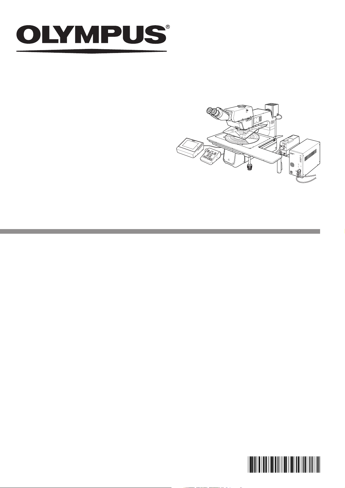
ASSEMBLY/SETUP
MANUAL
MX61A
MOTORIZED 300 mm COMPATIBLE
SEMICONDUCTOR/FPD INSPECTION
MICROSCOPE
This manual is for assembly and setup of the Olympus MX61A Semiconductor/FPD Inspection
Microscopes. To ensure the safety, obtain optimum performance and familiarize yourself fully with the
use of this microscope, we recommend that you study this manual thoroughly before operating the
microscope. As this manual will be needed when you replace the lamp or fuses or modify a setup,
retain it in an easily accessible place near the work desk for future reference.
A X 7 6 7 7
Page 2

Page 3

CONTENTS
MX61A
IMPORTANT – Be sure to read this section for safe use of the equipment. –
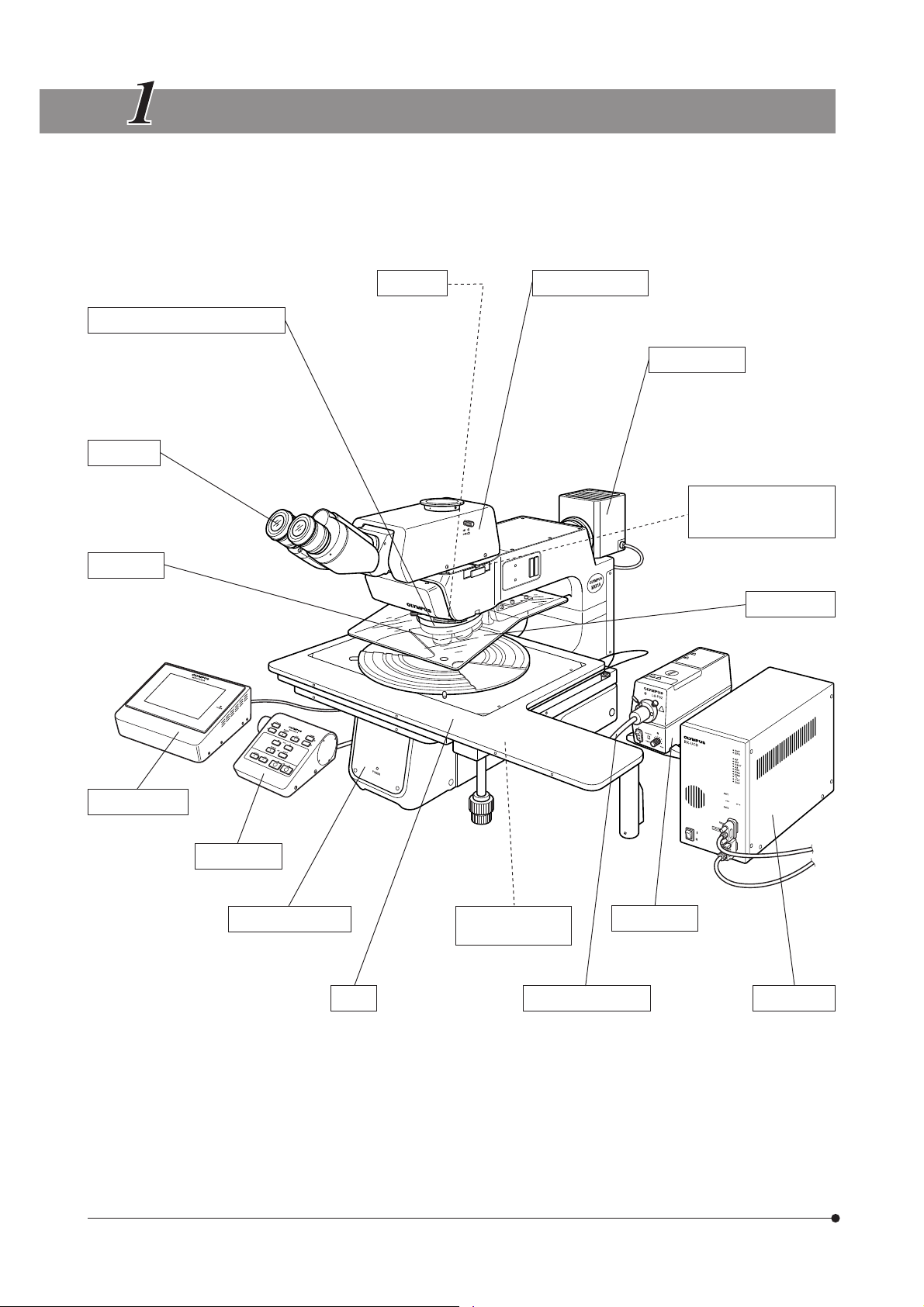
1 NOMENCLATURE
2 ASSEMBLY
2-1 Assembly Diagram ........................................................................................................................................................................... 12
2-2 Detailed Assembly Procedures ........................................................................................................................... 13-24
2-3 Modules Installed by Olympus...................................................................................................................................... 25
3 SETUP OF MX-OPU61A OPERATION UNIT
1 Initialization 2 USER Screen Setup
3 CONFIG 1/6 Screen Setup 4 CONFIG 2/6 Screen Setup
5 CONFIG 3/6 Screen Setup 6 CONFIG 4/6 Screen Setup
7 CONFIG 5/6 Screen Setup 8 CONFIG 6/6 Screen Setup
1-8
9-11
12-25
26-36
4
CENTRATION OF REFLECTED LIGHT APERTURE IRIS DIAPHRAGM
5 CENTRATION OF MERCURY/XENON BURNER
6 EXTERNAL CONTROL OF REVOLVING NOSEPIECE
1 Connector Used 2 Pin Layout and Signal Names
3 Revolving Nosepiece Position Numbers (Index Nos. on the Center of Revolving Nosepiece)
7 MAINTENANCE PARTS LIST
PROPER SELECTION OF THE POWER SUPPLY CORD ............................................................ 42,43
37
38,39
40
41
Page 4
IMPORTANT
This microscope employs a UIS2 (UIS) (Universal Infinity System) optical design, and should be used
only with eyepieces, objectives, observation tubes, etc. specified for use with the UIS2 (UIS) optics.
Less-than-optimal performance may result if inappropriate accessories are used.
The MX61A microscope is compatible with stage strokes of 200 mm (8 inches) and 300 mm (12
inches). Its control can be motorized by using the MX-OPU61A Operation Unit (with built-in computer)
and a PC in which the MX2-BSW Control Software is installed. The motorized control is also available
using the MX-HS61A Hand Switch with the jog dial control capability (the MX-OPU61A or the MX2-BSW
software should also be used in combination with the MX-HS61A Hand Switch).
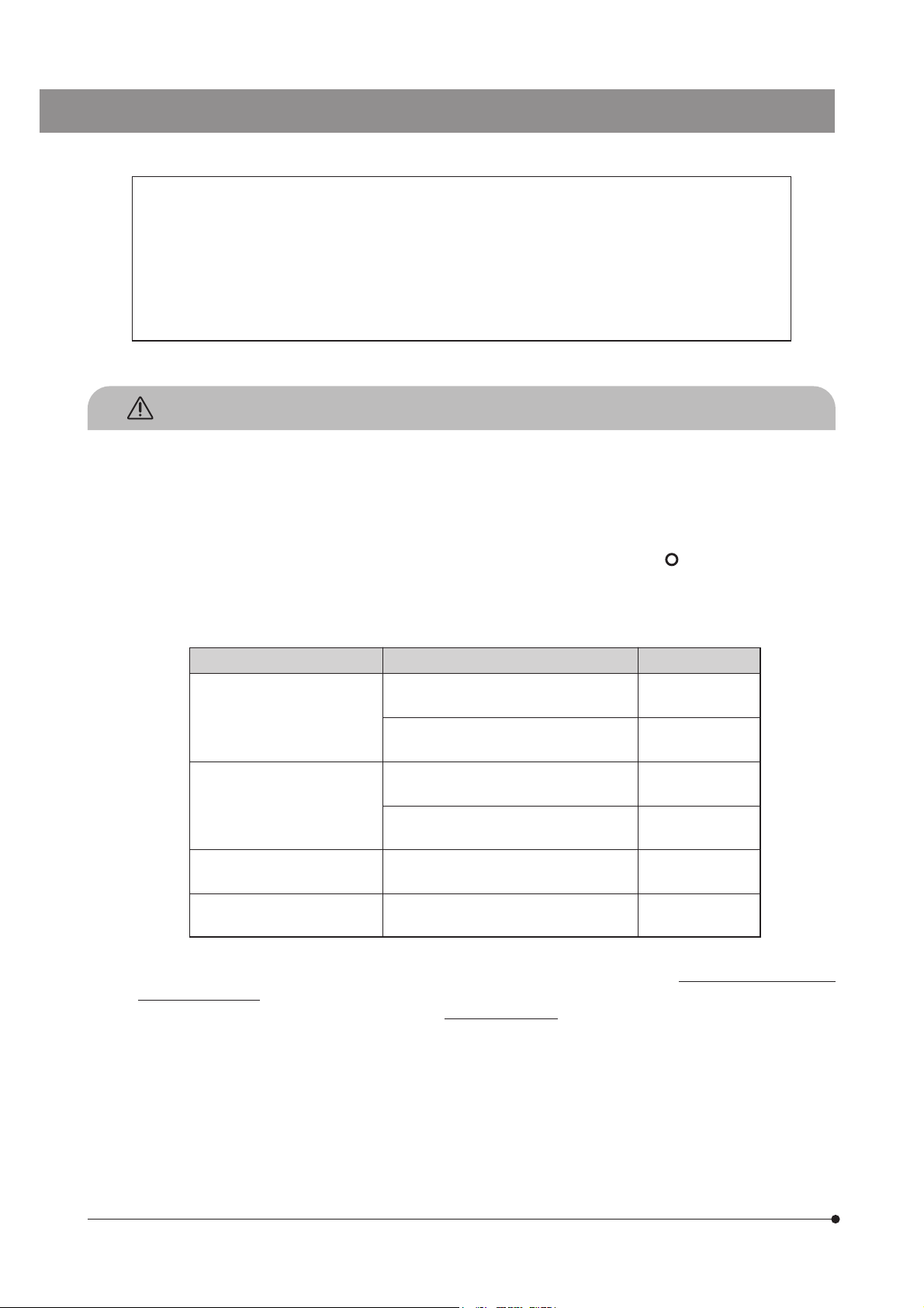
SAFETY PRECAUTIONS
1. Always use the power cord provided by Olympus. If no power cord is provided, please select the power cord by referring
to the section “PROPER SELECTION OF THE POWER SUPPLY CORD” at the end of this instruction manual. If the proper
power cord is not used, Olympus can no longer warrant the electrical safety performance of the equipment. Lay out the
power cord at a sufficient distance from the sources of heat such as the power supply unit/light source and lamp housing
to avoid contact with these heat sources.
2. To avoid potential shock hazard, always set the main switch of the BX-UCB control box to “
power cord before replacing the bulb/burner or connecting/disconnecting motorized parts. And since the system contains
motorized parts, do not plug in the power cord until all of the assembly procedures have completed.
}Always use the lamp bulb or burner supplied by Olympus.
” (OFF) and disconnect the
Bulb/Burner Model Average Life
Halogen bulb · 12V100WHAL-L (Long life type)
(PHILIPS 7724)
· 12V100WHAL (High-resolution type)
(PHILIPS 7023)
Mercury burner · USH-103OL
(USHIO)
· HBO103W/2
(OSRAM)
Xenon burner · UXL-75XB-A
(USHIO)
Halogen bulb for light guide
light source
3. Do not light the mercury or xenon burner while it is not mounted on the microscope because the UV rays in their light are
harmful to your eyes.
The used mercury burner should be disposed of as an industrial waste.
4. The eye point of this microscope can be adjusted in the range between 408 and 560 mm above the desktop surface (with
basic combination). According to the SEMI standard guidelines (SEMI S8-0705), prepare a microscope desk with an
optimum height for the application of the customer.
· JCR12V-100WB
(USHIO)
2000 hrs.
50 hrs.
300 hrs.
300 hrs.
200 hrs.
1000 hrs.
1
Page 5
MX61A
5. The desktop surface on which the microscope system is installed should be almost horizontal with a tilting angle of less
than 20’ with a 300 mm (12-inch) stage or less than 1° with a 200 mm (8-inch) stage (to prevent spontaneous displacement of the stage) and rigid.
(Weight of the microscope system with the basic combination for reflected light observation: 14x12-inch stage combination
— approx. 52 kg, 8x8-inch stage combination — approx. 45 kg)
}Although this microscope is designed with excellent vibration resistance, its maximum performance can be achieved
when an anti-vibration bench is used.)
6. The lamp housing surface at the rear of the microscope frame will become very hot during operation. When installing the
microscope, ensure that there are ample free spaces (of more than 100 mm) around and in particular above and below
the lamp housing. Also, the power cord and other cables should be laid out at distances from the microscope because
contact with them may result in their fusion and an electric shock due to it.
7. To avoid a potential shock hazard, make sure that the power cord is safety grounded/earthed.
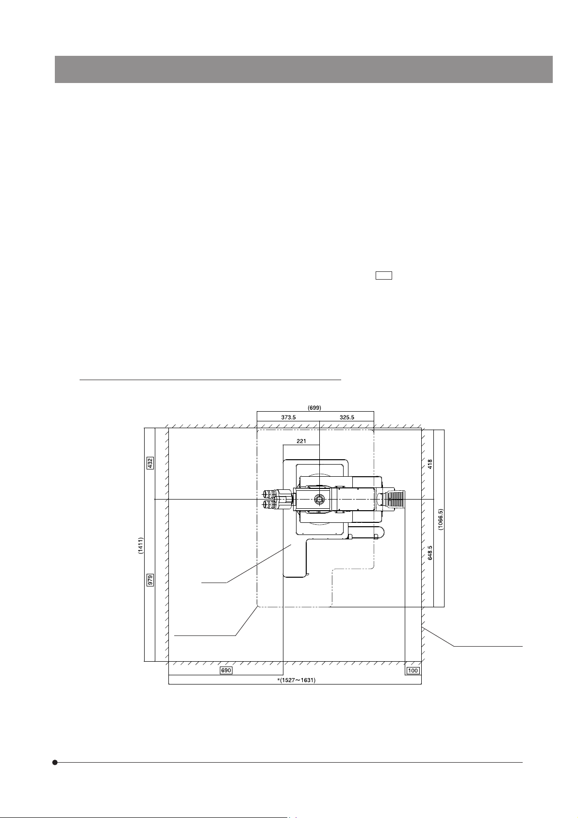
8. To allow each microscope manifest its full performance, reserve an installation space having the minimum dimensions
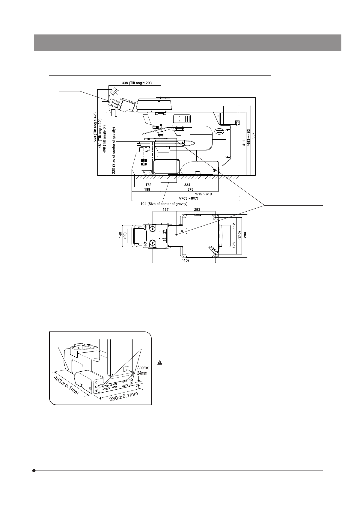
described below before assembly and installation of the microscope. (Sizes in )
}The dimensions of the area enclosed in alternate long and two short dashes lines indicate the stage movement range.
The dimensions marked * are variable depending on the lamp housing used.
}When maintenance is required, a larger workspace can be prepared by changing the observation tube orientation or
moving the stage.
}The following installation space is set according to the SEMI standard guidelines (SEMI S8-0705). It is recommended that
you set the optimum installation space for each customer based on the SEMI standard guidelines (SEMI S8-0705).
MX61A installation space: When the 14x12-inch stage is combined
MX61A
Stage movement
range
Unit: mm
Installation footprint
2
Page 6
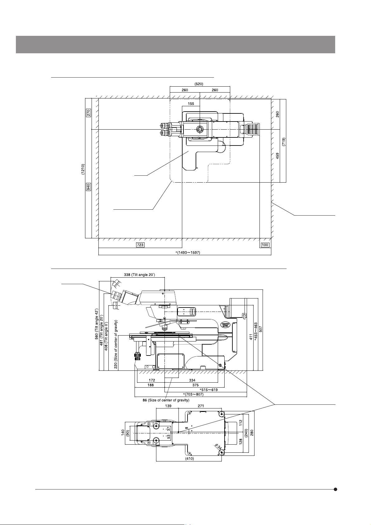
MX61A installation space: When the 8x8-inch stage is combined
MX61
Stage movement
range
Unit: mm
Installation space
MX61A external view, eye point and center of gravity: When the 14x12-inch stage is combined
Eye point
(Bottom view of microscope)
Unit: mm
Position of center of gravity
3
(Note) The center of gravity is an approximate position when the microscope is equipped with the basic combination for
reflected light oservation. Note that the position is variable depending on the weight of specimen, position of the
stage and other modules used.
Page 7
MX61A external view, eye point and center of gravity: When the 8x8-inch stage is combined
MX61A
Eye point
(Bottom view of microscope)
Unit: mm
Position of center of gravity
(Note) The center of gravity is an approximate position when the microscope is equipped with the standard module
combination for transmitted light observation. Note that the position is variable depending on the weight of specimen, position of the stage and other modules used.
9. To prevent toppling of the microscope system, keep the total height of the microscope below 1 meter (3.3 ft) when
attachments (including Olympus optional modules and the CCD camera prepared by the customer) are mounted.
10. Each microscope has screw holes (M5, depth 10 mm) for prevention of
@
²
Fig. 1
toppling (in the case of an earthquake or microscope imbalance) on the
side panels @ (x 2 holes) and the rear panel ² (x 2 holes). Clamp the
microscope using L-shaped clamps and these screw holes as required.
When clamping the microscope using L-shaped clamps prepared
by the customer, be sure to use steel bolts (strength category 12.9)
with as long as possible threaded sections (8 mm or more is recommended).
4
Page 8
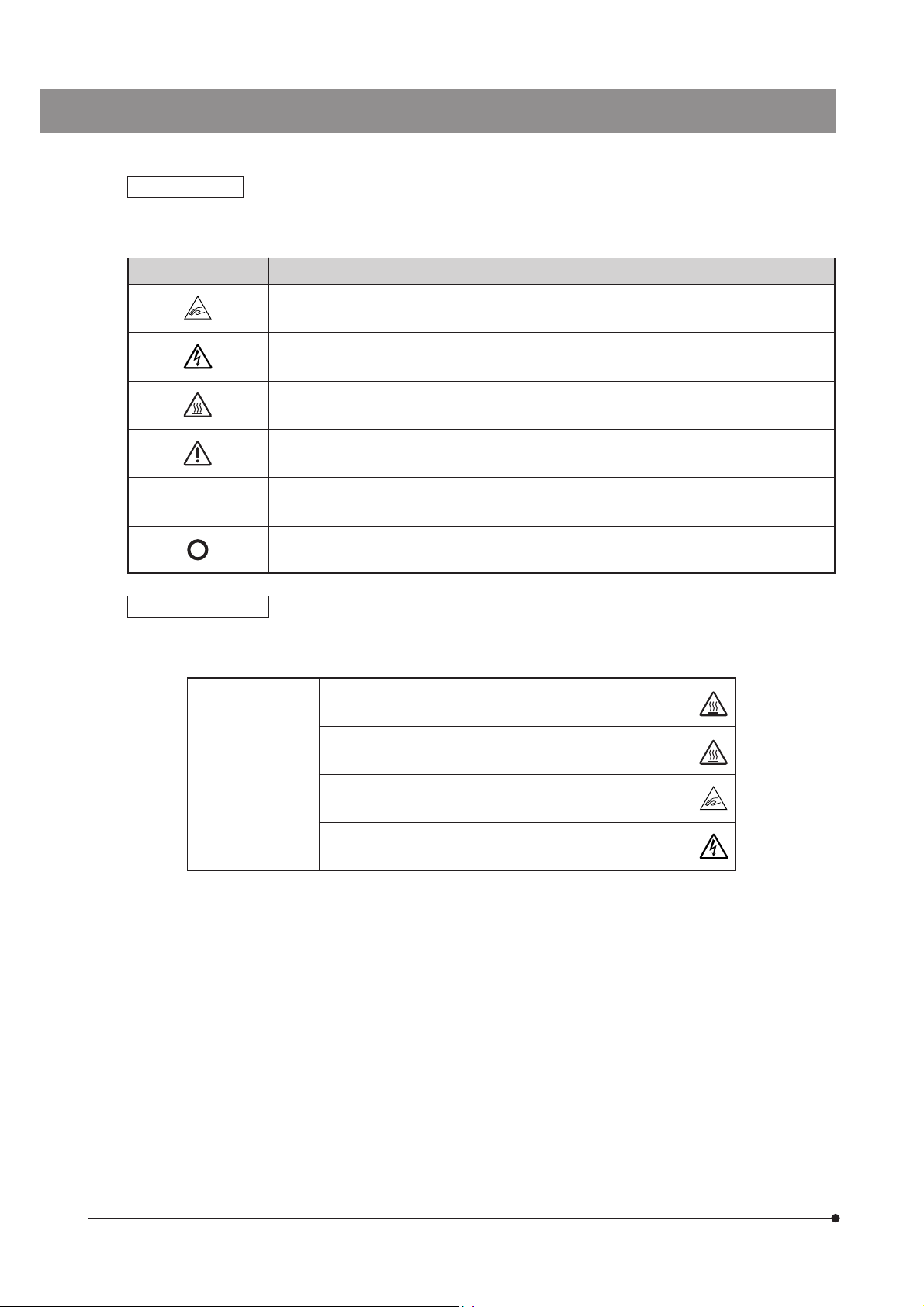
Safety Symbols
The following symbols are found on the microscope. Study the meaning of the symbols and always use the equipment
in the safest possible manner.
Symbol Explanation
Be careful not to have your finger caught by the stage or stage holder.
Be careful against high voltage (1 kV or more) applied inside the unit.
Indicates that the surface becomes hot, and should not be touched with bare hands.
Before use, carefully read the instruction manual. Improper handling could result in injury to the
user and/or damage to the equipment.
l
Indicates that the main switch is ON.
Indicates that the main switch is OFF.
Caution indications
Caution indications are affixed at parts where special precaution is required when handling and using the microscope.
Always heed the cautions.
Caution indication
positions
Lamp housing
/power supply unit
Light guide light source
(LG-PS2)
Front of base
(MX61A)
Power supply unit [High voltage caution]
[High temperature caution]
[High temperature caution]
[Caution against finger
catching]
5
Page 9
Getting Ready
1
@
²
Fig. 2
@
MX61A
1. Do not use the microscope where it is subjected to direct sunlight, high
temperature and humidity, dust or vibrations. (For the operating conditions,
refer to the INSTRUCTIONS manual’s chapter 8, “SPECIFICATIONS” on
page 43.)
2. A microscope is a precision instrument. Handle it with care and avoid
subjecting it to sudden or severe impacts. Never attempt to rotate the
motorized revolving nosepiece by hand; otherwise, the gear or other parts
may be damaged.
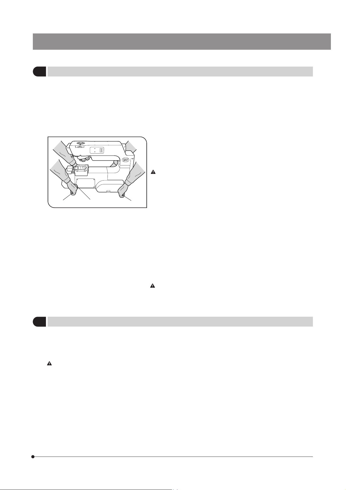
3. When moving the microscope, detach the observation tube, stage, lamp
housing and specimen to reduce the total system weight, then insert the
two provided carrying rods @ firmly into each of the left and right side
panels, and attach the two provided guarding parts ² on the two carrying
rods on the front.
If the guarding parts are not attached, the person holding the front
carrying rods may have a finger caught between the carrying rod
and the desktop.
Two persons are needed to carry the microscope; one should hold the
two front carrying rods and the other person should hold the rear carrying
rods. Be sure to move the microscope cautiously. (The microscope frame
weight is about 31 kg, or 68.2 lbs.)
}After movement, remove the guarding parts and carrying rods and retain
them carefully without losing. The carrying rods can be inserted in the
four threaded holes on the rear of the microscope. For the screw holes
left by removing the carrying rods, attach the provided screw caps on the
holes for the rear carrying rods and the cap seals on the holes for the
front carrying rods.
#Do not change the position of the microscope by sliding it on the
desktop surface; otherwise, the rubber feet will be damaged.
4. Be sure to attach the transport clamping plate(s) to the stage before
transporting it.
With the 14x12-inch stage combination, the center of gravity varies
greatly depending on the position of the stage. To ensure extra
stability, keep the two provided carrying rods attached to the mounting
holes on the front right side when using the microscope.
Maintenance and Storage
2
1. To clean the lenses and other glass components, simply blow dirty away using a commercially available blower and wipe
gently using a piece of cleaning paper (or clean gauze).
If a lens is stained with fingerprints or oil smudges, wipe it gauze slightly moistened with commercially available absolute
alcohol.
Since the absolute alcohol is highly flammable, it must be handled carefully.
Be sure to keep it away from open flames or potential sources of electrical sparks –– for example, electrical
equipment that is being switched on or off.
Also remember to always use it only in a well-ventilated room.
2. If any part of the equipment (other than glass components) gets dirty, with it with a clean cloth.
If the part is extremely dirty, do not attempt to use organic solvents to clean it; instead, use a soft, lint-free cloth slightly
moistened with a diluted neutral detergent.
3. Never disassemble any part other than instructed of the microscope. This could result in malfunctions or reduced
performance.
4. When not using the microscope, keep it covered with a dust cover. Make sure the lamp housing is cool before covering
the microscope.
5. When disposing of the microscope. Check the regulations and rules of your local government and be sure to observe
them.
6
Page 10
Applicable Standards
3
1. This device is in compliance with or certified by the following standards.
2. Although this device is designed for use in industrial environments, its full performances may not be manifested if it is not
operated properly. Be sure to handle it properly as instructed in this manual.
This device is designed for use in industrial environments (Class A device).
Using it in a residential environment may affect other equipment in the environment.
CE marking
This device complies with the requirements of both directive 89/336/EEC, 2004/108/EC concerning
electromagnetic compatibility and directive 2006/95/EC concerning low voltage. The CE marking indicates
compliance with the above directives.
FCC
This device has been subjected to the compliance evaluation of the following FCC regulation:
· FCC Part 15, Subpart B ClassA: Radio Frequency Equipment (Commercial and industrial areas)
NOTE: This equipment has been tested and found to comply with the limits for a Class A digital device,
pursuant to Part 15 of the FCC Rules. These limits are designed to provide reasonable protection
against harmful interference when the equipment is operated in a commercial environment. This
equipment generates, uses, and can radiate radio frequency energy and, if not installed and used in
accordance with the instruction manual, may cause harmful interference to radio communications.
Operation of this equipment in a residential area is likely to cause harmful interference in which case
the user will be required to correct the interference at his own expense.
FCC WARNING: Changes or modifications not expressly approved by the party responsible for compliance
could void the user’s authority to operate the equipment.
CALIFORNIA USA ONLY
This operation unit uses a Lithium Battery which contains Perchlorate Material - special handling may apply,
See www.dtsc.ca.gov/hazardouswaste/perchlorate.
SEMI
This device has been subjected to the compliance evaluations of the following guidelines under the S8 Standard.
· S2-0706: Safety Guidelines for Semiconductor Manufacturing Equipment
· S8-0705: Safety Guidelines for Ergonomics Engineering of Semiconductor Manufacturing Equipment
7
Page 11

MX61A
If the microscope is used in a manner not specified by this manual, the safety of the user may be imperiled. In addition,
the equipment may also be damaged. Always use the equipment as outlined in this instruction manual.
The following symbols are used to set off text in this instruction manual.
: Indicates that failure to follow the instructions in the warning could result in bodily harm to the
user and/or damage to equipment (including objects in the vicinity of the equipment).
<Reference>
# : Indicates that failure to follow the instructions could result in damage to equipment.
}: Indicates commentary (for ease of operation and maintenance).
8
Page 12
NOMENCLATURE
}The modules shown below are examples of those used in a typical system. Certain modules are usable even when they
are not mentioned below. For these modules, refer to the latest catalogues or contact Olympus.
For the modules marked *, refer to their instruction manuals.
Motorized Revolving Nosepiece
U-D6BDREMC
U-D5BDREMC
U-D6REMC
U-P5BDREMC
Eyepieces
SWH series
(FN 26.5)
Objectives
UIS2 (UIS) series
DIC Slider
U-DICRM*
U-DICR
(Not motorized)
U-DICRH
(Not motorized)
U-DICRHC
(Not motorized)
Observation Tube
MX-SWETTR (FN 26.5)
U-SWETTR-5 (FN 26.5)
Lamp Housing
U-LH100-3/LH100IR (Halogen bulb)
U-LH100HG/LH100HGAPO
(Mercury burner)
U-LH75XEAPO* (Xenon burner)
(Note) The MX-HGAD adapter is
required for the mercury
burner and xenon burner.
Intermediate Attachment
(Only one of the following
can be attached.)
U-UVF248IM*
U-AFA2M* (+ MX-ANM)
U-CFU*
Breath Shield
MX-BSH
MX-BSH-ESD-2
Operation Unit
MX-OPU61A
or
PC + MX2-BSW
9
Hand Switch
MX-HS61A
**
Microscope Frame
MX61A-F
Stage
MX-SIC1412R2
(For transmitted light/reflected
light observation)
MX-SIC8R
(For transmitted light/reflected
light observation)
Transmitted Light
Module
Flexible Light Guide
LG-SF
** Regarding the transmitted light module, please ask your Olympus dealer.
Light Source
LG-PS2*
Control Box
BX-UCB
Page 13
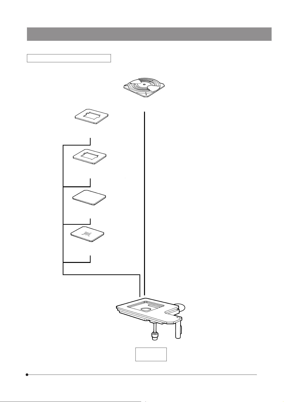
8x8-Inch Stage and Holder System
5-Inch Mask Holder
BH3-MH5
MX61A
Rotary Wafer Holder Plate
MX-WHPR86 (For 6-8 inch wafers)
4-Inch Mask Holder
BH3-MH4
Black Plate
BH3-SP6
Glass Plate
BH3-SPG6
8x8-Inch Stage
MX-SIC8R
10
Page 14
14x12-Inch Stage and Holder System
6-Inch Mask Holder
MX-MH6
Glass Plate
MX-SPG1412
14x12-Inch Stage
MX-SIC1412R2
Rotary Wafer Holder for 8-inch
and 12-inch wafers
MX-WHPR128
11
Page 15
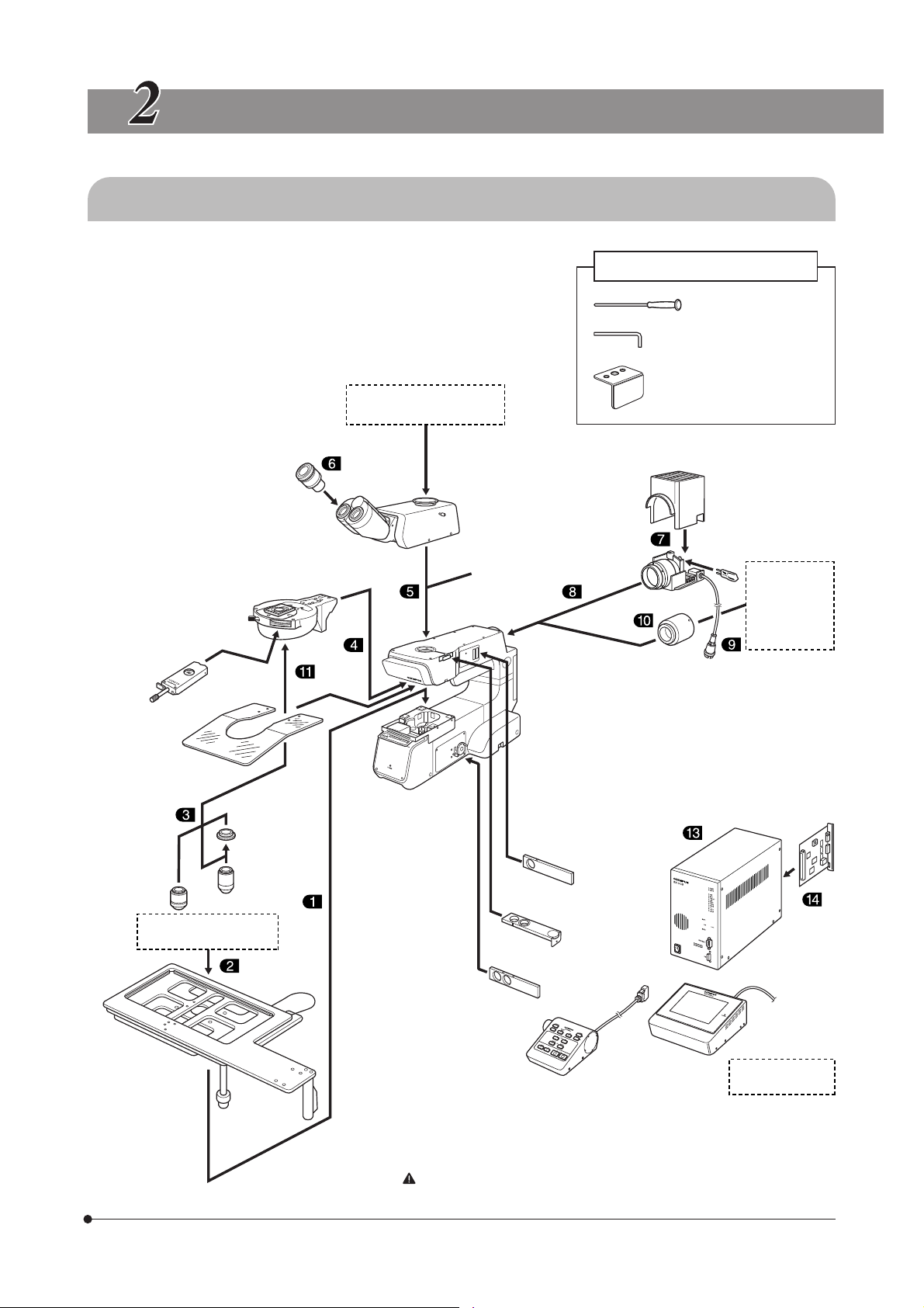
ASSEMBLY
2-1 Assembly Diagram
MX61A
}The diagram below shows where the various modules should be
mounted. Study the assembly instructions for only the modules to be
employed.
For the connection of cables and power cord, see page 21.
# When assembling the equipment, make sure that all parts are free
of dust and dirt and avoid scratching any parts or touching glass
surfaces.
Video/digital camera
Photomicrography system
Eyepieces
DIC Slider
U-DICRM
U-DICR
U-DICRH
U-DICRHC
SWH series
Motorized Revolving
Nosepiece
U-D6BDREMC
U-D5BDREMC
U-D6REMC
U-P5BDREMC
Observation Tube
MX-SWETTR
U-SWETTR-5
(Provided with the microscope frame)
Intermediate Attachment
(Only one of the following
can be attached.)
U-UVF248IM
U-AFA2M
(+ MX-ANM)
U-CFU
Tools Used
Allen screwdriver (3 mm)
Allen wrench (3 mm)
Tool holder
Lamp Housing
for Halogen Bulb
U-LH100-3
LH100IR
Halogen bulb
12V100WHAL-L
12V10WHAL
High-Intensity
Lamp Housing
U-LH75XEAPO
U-LH100HG
LH100HGAPO
Adapter
MX-HGAD
Breath Shield
MX-BSH
MX-BSH-ESD-2
Brightfield/
darkfield
objective
(See pages 10 & 11.)
Stage
MX-SIC1412R2
MX-SIC8R
Holders
Brightfield
Objective
Adapter
BD-M-AD
Brightfield
objective
Microscope Frame
MX61A-F
Filters
U-25D6-2
U-25ND25-2
U-25LBD
U-25IF550, etc.
Analyzer
U-AN360-3
Polarizer
U-PO3
Hand Switch
MX-HS61A
Control Software
PC + MX2-BSW
}The tools used can be stored in the holes on the tool holder provided
with the microscope frame. Use the double-sided adhesive tape of the
tool holder to attach it to a position that does not hinder operation.
Do not attach the tool holder anywhere near the bottom of the lamp
housing since it generates high-temperature heat.
Control Board
U-ZPCB or
U-AFA2M-CB
+ U-DICPCB
Control Box
BX-UCB
Operation Unit
MX-OPU61A
12
Page 16

2-2 Detailed Assembly Procedures
}If the stage is expected to carry a heavy load, use the support spring unit (to be installed by Olympus dealer).
The system contains motorized parts. Do not plug in the power cord until all of the assembly procedures have
completed.
@
Fig. 3
Fig. 4
³
²
|
Attaching the Stage
1
1. Using the Allen screwdriver (3 mm), remove the transport clamping plate
@ from the rear edge of the stage. (Fig. 4) The removed screws should be
used to clamp the stage when attaching it.
# Two transport protection sheets are placed in the gaps of the MX-
SIC8R stage. Be sure to remove them before using the system.
2. While holding the stage so that the coarse adjustment grip and X-axis/Yaxis knobs are on the right, gently place the stage on the stage holder ².
Using the Allen screwdriver or Allen wrench, tighten the four screws temporarily.
3. Remove the transport clamping plate(s) from the front ³ and side (MXSIC1412R2 only) | of the stage, move it to the rearmost position and,
after confirming that the stage and arm do not interfere with each other,
tighten the four screws firmly. (Fig. 4)
# The clutch and belt may stick together and prevent smooth opera-
tion of the release function if the stage has not been moved for a
long time. If this phenomenon occurs, take the remedial action described in page 26 in the instruction manual.
When the 14 x 12 inch stage is combined, the position of the center
of gravity varies greatly depending on the position of the stage. Attach
the provided carrying rod to the front right side of the microscope
frame to prevent accidental overturning of the system when using
the 14 x 12 inch stage.
(Figs. 3 & 4)
13
Caution Before Transporting the Stage (Fig. 4)
Before transporting the stage, be sure to attach the transport clamping
plates @³| and package the stage carefully. Do not transport the stage
when it is attached to the microscope frame or inadequately packaged.
Otherwise, the stage will be damaged.
Page 17

MX61A
²
|
Fig. 5
Fig. 6
@
³
Attaching the Holders
2
#Attach a holder in the orientation so that the notch on the holder’s
side faces left. The adjustment of the levelness is performed in this
orientation.
Attaching the Wafer Holder (Fig. 5)
1. Insert the wafer holder plate @ into the stage, one edge first.
2. Push the wafer holder plate from above to make sure that it sits correctly
with no tilt.
3. Using a flat-blade precision screwdriver, clamp the plate by tightening
the holder clamping screw ² on the left side of the stage.
#The levelness of the holder is adjusted by the heights of the three
screws on the back side of the stage. Do not push positions near
the holder, for this may tilt the holder.
Attaching the Mask Holder (Fig. 6)
1. Carefully place the mask holder ³ on the stage surface, making sure
that it sits correctly with no tilt.
2. Using the precision screwdriver, clamp the plate by tightening the holder
clamping screw | on the left side of the stage.
Attaching the Black Plate/Glass Plate
Carefully place the plate on the stage surface, and tighten the holder
clamping screw on the left side of the stage.
#When attaching the glass plate, do not tighten the clamping screw
excessively as the glass plate may break. Tighten to the extent that
the glass plate does not rattle noticeably when attached.
(Figs. 5 & 6)
ƒ
Fig. 7
ƒ
Adjusting the Levelness of Holder Plate (Fig. 7)
The levelness of the stage travel (movement) and the top surface of the
wafer holder have been adjusted at the factory. If finer adjustment is
required or when using a holder from a manufacturer other than Olympus,
apply drops of alcohol on the three adjustment screws ƒ to loosen the
screw lock, then adjust the heights of the screws by inserting a flat-bladed
screwdriver from below.
#The maximum loads of the stages including the holders are as fol-
lows.
MX-SIC8R : 2 kg (4.4 lbs.)
MX-SIC1412R2 : 3.5 kg (7.7 lbs)
14
Page 18

Fig. 8
@
Attaching the Objectives
3
# Never attempt to rotate the motorized revolving nosepiece by hand.
Rotating by hand may cause malfunction or damage. Remove the
cap from each objective mount hole.
1. Following the order of numbers 1 to 5 or 6 indicated on the objective
mount thread @, screw objectives into the objective mount threads by
starting with the objective with the lowest power.
# The rotation of the revolving nosepiece can be made smooth by
mounting objectives uniformly in all of the nosepiece positions.
Therefore, the objectives that are not used frequently should also be
mounted. Be sure to attach the caps to the unused objective mount
hole.
Using the Brightfield Objective Adapter
When mounting a brightfield objective on a revolving nosepiece designed
for brightfield/darkfield objectives, mount each objective by means of the
BD-M-AD objective adapter.
Note that this adapter degrades the autofocusing performance if it is
used during autofocusing (using a high-power objective).
(Fig. 8)
@
Fig. 9
@
Attaching the Motorized Revolving Nosepiece
4
# It is only the U-D6BDREMC, U-D5BDREMC, U-D6REMC or U-P5BDREMC
revolving nosepiece that can be used.
# When mounting the revolving nosepiece, remove the stage holders
to ensure that the objectives do not touch the stage.
# Slide the revolving nosepiece all the way into the dovetail mount
until it stops.
# The revolving nosepiece is a heavy module. Take care not to drop it
during mounting.
1. Loosen the revolving nosepiece clamping screw @ using the provided
Allen screwdriver, slide the revolving nosepiece all the way into the dovetail mount until it stops, and tighten the clamping screw @.
# If the clamping screw is tightened without sliding the revolving nose-
piece all the way, the clamping section may be deformed, the revolving nosepiece may become irremovable, and the connector
contact failure may occur also.
2. Set the DIP switches for the mounted revolving nosepiece (see page 22
for the setup method).
Attaching the Observation Tube
5
# Do not hold the observation tube by the binocular section. Since the
binocular section is movable, the observation tube may not be fitted
into the circular dovetail correctly resulting in incomplete attachment.
1. Using the provided Allen screwdriver, fully loosen the observation tube
clamping screw @.
2. Insert the circular dovetail mount at the bottom of the observation tube
into the observation tune mount on the top surface of the arm.
3. Clamp the observation tube by tightening the clamping screw @.
(Fig. 9)
(Fig. 10)
15
Fig. 10
Page 19

MX61A
@
²
@
²
Fig. 11
Fig. 12
Attaching the Eyepieces
6
Fit and insert gently an eyepiece into each eyepiece sleeve.
#Both the left and right eyepiece sleeves have the eyepiece posi-
tioning grooves ². Be sure to fit the positioning pin @ of the eyepiece into the positioning groove ² of the eyepiece sleeve when
mounting each eyepiece.
Attaching the Halogen Bulb
7
}The applicable halogen bulbs are the 12V100WHAL-L long-life bulb
(PHILIPS 7724) and the 12V100WHAL high-intensity bulb (PHILIPS 7023).
1. Using the Allen screwdriver provided with the microscope, fully loosen
the clamping screw @ on the top of the lamp housing.
2. Lift the lamp housing ² to remove.
3. Tilt the lamp socket ³ by 90° in the direction of the arrow.
4. While holding down the lamp clamping lever |, hold the halogen bulb
ƒ by means of a piece of gauze, and insert the pins … all the way into
the pin holes †.
Return the lamp-clamping lever to the original position to clamp the bulb.
(Fig. 12 to 14)
(Fig. 11)
|
Fig. 13
Fig. 14
ƒ
†
³
…
Do not touch the bulb directly with bare hand. If fingerprints are
attached on it, wipe thoroughly with a soft cloth to prevent the service life from dropping and the bulb from cracking.
5. Fit the lamp housing ² from above and tighten the clamping screw @
while pushing down the screw by force. (Fig.12)
Bulb replacement during use or right after use
The bulb. lamp housing and areas near these will be extremely hot
during and right after use.
After setting the main switch to “ ” (OFF) and unplugging the
power cord from the power outlet, allow the old bulb and lamp
socket to cool before replacing the bulb with a new one of the
designated type.
16
Page 20

³
Fig. 15
²
|
@
Attaching the Lamp Housing
8
1. Fit the lamp housing @ all the way into the lamp housing mount on the
rear of the microscope arm.
Attach the lamp housing so that the heat radiating fins ² face upward. To prevent a fire hazard, reserve ample spaces above, below
and on the rear of the lamp housing.
2. After fitting the lamp housing @, tighten the two clamping screws ³
using the Allen screwdriver provided with the microscope.
# Do not tighten the screws too much, as this may deform the lamp
housing mount.
3. For the connection of the connector | of the lamp housing, see
“
12 Connecting the Module Connection Cables” (page 21).
(Fig. 15)
³
Fig. 16
Fig. 17
@
²
|
Attaching the Mercury Burner
9
}For the xenon burner, attach the burner, reset the hour counter and con-
nect the cables as described in the manual provided with the light source
in use.
1. Loosen the socket clamping screw @ using the Allen screwdriver.
2. Hold the upper section of the lamp housing and pull it upward to remove
the socket section.
# To prevent malfunction, do not hold the lamp housing by the center-
ing knobs ².
3. Place the socket section upside down as shown in Fig. 17.
}The lamp housing is equipped with the holder for transportation in the
factory shipment condition or with an old burner when the burner is
replaced. Remove the holder or old burner by loosening the two burner
holding screws ³.
4. Attach the + (positive) pole of a specified mercury burner | to the fixed
mount on the upper side, then the - (negative) pole to the mount on the
lower side.
# Be sure to use the USH-103OL (USHIO) or the HBO103W/2 (OSRAM)
mercury burner.
Be careful and avoid leaving fingerprints or contaminants on the
mercury burner. Otherwise, there is a danger of explosion due to
distortion of glass caused by the stains. If the burner is contaminated, clean it by wiping gently with gauze slightly moistened with
absolute alcohol.
5. Attach the socket section with burner to the original position and tighten
the socket clamping screw @.
# Align the external edges of the lamp housing with those on the
socket section, and push the lamp housing straight downward.
Attach the lamp housing so that the heat radiating fins face upward.
To prevent a fire hazard, reserve ample spaces above, below and on
the rear of the lamp housing.
Do not light the mercury burner while it is not mounted on the microscope because the UV rays in its light are harmful to your eyes. Also,
the UV rays in the light of the mercury burner may damage the specimen if this is sensitive to UV rays.
(Figs. 16 & 17)
17
Page 21

@
MX61A
Resetting the Burner Hour Counter
1. Press the center section @ of the reset switch ² on the front panel to
reset the counter reading to “000.0”.
}The hour counter shows elapsed time in hours. The service life of a
mercury burner is 300 hours. For safety’s sake, replace the burner when
the hour counter reads “300.0”.
Fig. 18
²
Fig. 19
Mercury Burner Replacement
1. The service life of the mercury burner is 300 hours. In order not to
impair the safety of the equipment, replace the burner when it has
been used for 300 hours (USH-103OL, HBO103W/2). The burner
may crack if used beyond the specified life time.
When the end of the burner’s service life is near, flickering is likely
to increase. It is therefore recommended to replace the burner according to the purpose of observation.
* This value assumes light cycles composed of 2 hours of lighting
and 30 minutes of extinction (with the USH-103OL). Do not turn it
on and off at a shorter cycle than the above, for this will shorten the
service life of the burner.
2. Before replacing the burner, wait at least 10 minutes, or until the
burner and lamp housing have cooled down, after turning the burner
off. Before removing the burner, confirm that the main switch is “ ”
(OFF) and unplug the connecting cord from the output connector
of the power supply.
Refer to page 17 for details on replacement procedure.
3. After replacing the burner, reset the hour counter to “000.0” as outlined above.
18
Page 22

Setting Up the Power Supply Unit for Mercury Burner
³
Fig. 20
|
Fig. 21
ƒ
@
²
CAUTION This operation should be performed after completing the
attachment of the lamp housing described in the next
section.
Cables and cords are vulnerable to bend or twist. Do not apply
excessive force to them.
Make sure that the main switch is set to “ ” (OFF) before connecting cords and cables.
Always use the power cord provided by Olympus. If no power cord
is provided, please select the power cord by referring to the section “PROPER SELECTION OF THE POWER SUPPLY CORD” at the
end of this instruction manual. If the proper power cord is not used,
Olympus can no longer warrant the electrical safety performance
of the equipment.
1. Make sure that the voltage and frequency of the input power are within
the ranges indicated on the name plate @.
(100 V systems can be used with voltages in the 100 to 120 V range and
200 V systems can be used with voltage in the 220 to 240 V range, both
with frequencies of 50 to 60 Hz.)
2. Plug the connection cord to the connector ² on the power supply unit.
3. Attach the power cord to the power input connector ³ of the power
supply unit, and plug the power plug | of the power cord into the wall
power outlet ƒ.
Always ensure that the grounding terminal is safety grounded/
earthed. If the equipment is not grounded/earthed, Olympus can no
longer warrant the electrical safety performance of the equipment.
19
Fig. 22
@²³
Attaching the High-Intensity Light Source
10
Lamp Housing
1. Fit the MX-HGAD adapter @ all the way into the lamp housing mount on
the rear of the microscope arm, tighten the two clamping screws ² using the Allen screwdriver.
2. Fit the mount section of the high-intensity lamp housing into the adapter,
confirm that the lamp housing is not tilted, and clamp the two clamping
screws ³ using the Allen screwdriver.
When the high-intensity light source is used, the brightness becomes
too high during brightfield observation. Be sure to install the provided ND filter (ND0.5*) in the brightfield observation light path.
* If the brightness after insertion of the ND0.5 filter is too low, use a different
ND filter (ND3 and ND6 filters available as options).
}The ND0.5 filter provided with the lamp housing can be mounted only by
the Olympus qualified personnel.
(Fig. 22)
Page 23

MX61A
²
³
|
Fig. 23
@
Attaching the Breath Shield
11
(MX-BSH or MX-BSH-ESD-2)
1. Attach the two breath shield mounting brackets @ on the breath shield
² using the provided screws (shorter ones).
For the present, tighten the screws temporarily using the Allen screwdriver. (If they are attached completely, it becomes impossible to attach
the breath shield to the microscope frame.)
2. Align the attaching holes | on the mounting brackets with the breath
shield screw holes ³ on the microscope, and clamp using the provided
screws (longer ones).
3. Now tighten the screws that have been secured temporarily in step 1
above.
# Tighten the screws lightly to prevent the breath shield from cracking.
(Fig. 23)
20
Page 24

Connecting the Module Connection Cables
12
Since this system includes motorized modules, do not connect the power cord until all other connections have
been completed.
Cables and cords are vulnerable to bend or twist. Do not apply excessive force to them.
Always connect the module designated by Olympus to each connector. Insert each connector in the correct
orientation and tighten the clamping screws if these are provided.
Use a PC that complies with the IEC60950-1 requirements. Otherwise, we cannot guarantee the performance of
the entire system.
# Always use a commercially available straight cable as the RS232C cable (use of an inappropriate cable may
result in failure). The cable should be equipped with D-sub 9-pin (female) connectors on both ends.
When the MX-OPU61A is used, the RS232C cable is provided.
Motorized
DIC Slider
U-DICRM
Motorized
Analyzer
MX-ANM
Control Box
BX-UCB
Microscope
MX61A
Active AF Unit
U-AFA2M
Remote Cable
U-RMT
Rear view of the
base of MX61A
Unused
connector
Control
Board
U-ZPCB or
U-AFA2M-CB
To
U-UVF248LBM
Rear panel
of BX-UCB
21
RS232C cable
} The MX-OPU61A
Computer
(running MX2-BSW software)
is not required if
a computer is
used.
RS232C
cable
RS232C cable
Power Cord
RS232C cable
Operation Unit
MX-OPU61A
Option Board
U-DICPCB
Power Cord
Hand Switch
MX-HS61A
Page 25

MX61A
Setting the DIP Switches
13
@
Fig. 24
DIP switches
DIP SW1
(Upper switch)
12345678
0
1
²
³
Switch bits (ON: 1, OFF: 0)
00
01
10
11
0
0
0
1
0
1
(Fig. 24)
}The following table shows the details of DIP switch settings.
#Set the main switch @ of the microscope to “ ” (OFF) before setting
the DIP switch.
This is because the DIP switch settings are read and entered only at
the moment the microscope is turned ON.
#Before setting the DIP switches, discharge the static electricity from
your body by lightly touching any metallic object.
1. When using the U-D6REMC or U-D6BDREMC revolving nosepiece, be
sure to set DIP SW1 bit 3 ² to “ON”.
When using the U-D5BDREMC or U-P5BDREMC revolving nosepiece,
leave the DIP SW1 bit 3 in the default setting of “OFF”.
2. To inhibit initialization at the moment the microscope is turned ON, be
sure to set DIP SW1 bit 7 ³ to “ON”.
Function Setting Result
Buzzer inhibition Generate buzzer
Do not generate
Revolving nosepiece type
Reserved for maker Fixed at OFF
Reserved for maker Fixed at OFF
Freedom
(number of positions) search
Power-ON initialization inhibition
U-D5BDREMC/ U-P5BDREMC
U-D6REMC/ U-D6BDREMC
Not used
Not used
Search during power ON initialization
Do not search
Initialize
Do not initialize
SW2
(Lower switch)
}The masked fields indicate the factory setups (all OFF).
00000000
Reserved for maker All fixed at OFF
22
Page 26

²
@
Attaching the AF Control Board
14
# Be sure to set the main switch of the BX-UCB control box to “ ” (OFF)
before mounting the U-ZPCB or U-AFA2M-CB auto focusing control
board in it.
CAUTION If any Z-focus control board is mounted in the BX-UCB,
remove it before proceeding. Otherwise, a failure may
result.
(Fig. 25)
Fig. 25
1. Loosen the six clamping knobs from the two option slot covers on the
rear of the BX-UCB @, and remove the option slot covers together with
the clamping knobs.
}Attach the removed clamping knobs on the AF control board ² so that it
can be inserted or removed by holding the clamping knobs.
2. Aligning the orientations of the connector of the AF control board ² with
that inside the BX-UCB, insert the AF control board into the BX-UCB
along the board rails.
Push the AF control board all the way until the connectors are connected
firmly.
3. Clamp the AF control board ² with the clamping knobs above.
Also attach one of the option slot covers in the same way.
}Retain the unused option slot cover in a safe place.
}When using the U-DICRM motorized DIC slider, it is also necessary to
mount the U-DICPCB DIC/DUV option board now (for details, see the
instruction manual for the U-DICRM).
23
Page 27

MX61A
²
³
Fig. 26
Fig. 27
³
MX-OPU61A
BX-UCB
²
Connecting the Power Cord
15
Cables and cords are vulnerable to bend or twist. Do not apply excessive force to them.
Make sure that the main switch @ is set to “ ” (OFF) before connecting cords and cables.
Always use the power cord provided by Olympus. If no power cord
is provided, please select the power cord by referring to the section
“PROPER SELECTION OF THE POWER SUPPLY CORD” at the end of
this manual. If the proper power cord is not used, Olympus can no
longer warrant the electrical safety performance of the equipment.
1. Connect the power cord plug ² to the AC receptacle ³.
Connect the provided power cord correctly and ensure that the
grounding terminal of the power supply and that of the 3-conductor
wall outlet are properly connected. If the equipment is not grounded/
earthed, Olympus can no longer warrant the electrical safety performance of the equipment.
2. Connect the power cord plug | to a 3-conductor power outlet ƒ.
(Figs. 26 to 28)
|
Fig. 28
Fig. 29
ƒ
Bundling the Cables
16
}The cables can be bundled using the provided binding part.
1. Wrap the binding part around the bundled cables and fix them by engaging the hook.
(Fig. 29)
24
Page 28

2-3 Modules Installed by Olympus
Assembly and adjustment of the following modules will be performed by Olympus personnel.
Installation of the Support Spring Unit
1
Setup of the OP Light Path (installation of the Mirror Unit)
2
Installation of the Reflected Neutral Density Filter ND 0.5/ND3/ND6
3
Installation of the AF Cover MX-AFC
4
25
Page 29

MX61A
SETUP OF MX-OPU61A OPERATION UNIT
}To operate the control panel, touch the desired switch on the screen with a fingertip (a glove acceptable or a commer-
cially available touch pen also acceptable).
· Select switch: When this kind of switch is touched, the switch is displayed in green to indicate that it is selected. (The
STAGE ESC switch is displayed in red when it is selected.)
· Screen switch: When this kind of switch is touched, the screen is switched to the next screen.
· Adjustment switches: When this kind of switch is either touched shortly or held for a longer period, the selected value
is varied upward or downward.
· Grayed-out switch: This kind of switch is defeated because no function is set for the switch or the module assigned for
the switch is not set or not controllable.
}When any of the CONFIG 1/6 to 6/6 screens is displayed, the MX-HS61A hand switch cannot be used except for the jog
dial.
}By pulling out the tilt legs on the bottom surface, you can adjust the installation angle of the touch panel surface.
# Do not apply excessive force to the touch panel and the tilt legs (when pulled out) of the MX-OPU61A. Doing so
could break the touch panel surface.
26
Page 30

@
|
USER screen 1
²
USER screen 2
ƒ
Initialization
1
}Be sure to set DIP SW1 bit 7 of the BX-UCB control box to “ON”.
}Do not alter the settings of the DIP switches of the Z-board and AF board.
1. Set the main switches of the BX-UCB control box and MX-OPU61A operation unit to “ ” (ON).
The microscope’s Z-stage will be initialized and the application will start
up automatically.
}It takes about 40 seconds to start up the application.
}The initialization time of the Z-stage varies depending on the position of
the Z-stage. The startup of the application will not finish during the
initialization of the stage (an error message will be displayed).
2. When the MX-OPU61A is used for the first time, message “Please restart
BX-UCB” is displayed on the screen. When this message is displayed,
set the main switch of the BX-UCB to “ ” (OFF) then “ ” (ON) again.
3. When the BX-UCB is turned ON again, the application installed in the
MX-OPU61A starts up automatically. (“INITIALIZING - - -” is displayed until
the USER screen is displayed.)
4. Advance to the next USER screen setup.
}An error message and remedy information are displayed in case of a
trouble. If this happens, follow the instruction of the displayed message.
USER Screen Setup
2
}USER switches 1, 2 and 3 can be used to assign three sets of setups for
various observation methods and/or specimens.
1. Touch the USER1 (or 2 or 3) switch @.
If this is the first time, the default settings are displayed because no CONFIG
information has been set up. (An alarm that the actual unit information
differs from the setting information is displayed at this time.)
2. Touching one of the USER switches enables the SET UP switch ² that
has previously been grayed out. Touch the SET UP switch to display the
PASSWORD screen.
3. Input “69612” as the password. (The password is fixed.)
4. Touch the OK switch ³ to display the CONFIG 1/6 screen.
}An alarm message is displayed if the input password is incorrect.
# Set the upper and lower limits of the focusing mechanism of CONFIG
2/6 every time the thickness of a specimen changes.
27
PASSWORD screen
³
Other Switches
|UNIT INFO:
Touch this switch to open the UNIT screen, in which the unit connection
status after initialization is displayed.
---->
---->
---->
---->
DIC:
AN:
HS:
AF:
---->
REVO:
“CONNECT” when connected,
“- - -” when not connected.
Revolving nosepiece connection status
“5” with a 5-position revolving nosepiece.
“6” with a 6-position revolving nosepiece
DIC prism unit connection status
Analyzer unit connection status
Hand switch connection status
AF unit connection status
ƒOK:
Touch this switch to display the observation operation screen.
Page 31

@
ƒ
CONFIG 1/6 screen
|
Objective name selection 1/3 screen
…
²
³
CONFIG 1/6 Screen Setup
3
}When any of the CONFIG screens is displayed, the MX-HS61A hand
switch cannot be used except for the jog dial.
}The CONFIG 1/6 screen is used to set the basic configuration of the
microscope.
Setting the Name and Magnification of Objective (OB)
}When a 5-position revolving nosepiece is used, the switches for data 6
are grayed out.
1. If an objective name displayed as the default is incorrect, touch the
switch @ below the objective name to open the objective name selection screen.
2. Touch the desired objective name ² and touch the OK switch ³ to enter
it. If the desired objective name is not shown in the objective name selection screen, touch the page up/down switch | until the desired objective name is displayed (a total of 3 pages are provided).
3. When the objective name is entered with the OK switch, the CONFIG 1/
6 screen is displayed again.
4. If the displayed objective magnification is incorrect, touch the
ƒ below the magnification to open the objective magnification selection
screen.
5. Touch the correct objective magnification … and touch the OK switch †
to enter it.
6. Correct other objective names and types if they are incorrect.
}Set the idle position (- - -) for the objective No. where an objective is not
mounted. This omits unnecessary setup operations. After the objective
No. is set as the idle position, the objective name will be “NONE”.
MX61A
switch
Objective magnification selection screen
†
28
Page 32

@
CONFIG 1/6 screen
²
|
AS preset selection screen
³
Setting the AS preset values (AS PRESET)
}After the objective names and magnifications have been set up, the rec-
ommended AS preset values are set automatically. The preset values
extend in the range from 1 to 13 (aperture iris diaphragm fully open to
fully closed). If “- - -” is set, the interlocking is disabled.
1. If it is required to modify a recommended preset value, touch the
switch @ below the preset value to open the AS preset selection screen.
2. Touch the desired AS preset value ² and touch the OK switch ³ to enter it.
If the desired AS preset value is not shown in the AS preset value selection screen, touch the page up/down switch | until the desired AS preset value is displayed (a total of 3 pages are provided).
3. Touch the OK switch to display the CONFIG 1/6 screen again.
AS Preset Values
OB magnification
OB type
UMPlan FL
UMPlan FL-BD
MPlan FL
MPlan FL-BD
LMPlan FL
LMPlan FL-BD
MPlan FLN
MPlan FLN-BD
LMPlan FLN
LMPlan FLN-BD
MPlan N
MPlan N-BD
LMPlan Apo
LMPlan Apo-BD
1.25 2.5 5 10 20 40 50 100 150
----334 68--
-- -- 3 3 4 -- 6 8 --
-- -- 4 4 5 -- 8 9 --
22 --
-- -- 9
-- -- 4 4 5 -- 8 9 --
-- -- 3 3 4 -- 6 8 --
-- -- -- -- -- -- -- -- 10
334--68
5
--
29
Page 33

@
CONFIG 2/6 screen
²
MX61A
Setting the Focus Step (FOCUS SETUP)
}The recommended focus step values for the objective magnifications
are displayed as the default values.
The focus step refers to the Z-stage displacement per touch of the focus
fine adjustment switch.
1. If it is required to modify a recommended focus step value, touch the
switch @ below the preset value to open the focus step selection
screen.
2. Touch the desired focus step value ² and touch the OK switch ³ to
enter it.
If the desired focus step value is not shown in the focus step selection
screen, touch the page up/down switch | until the desired focus step
value is displayed (up to a total of 2 pages are provided).
3. Touch the OK switch to display the CONFIG 1/6 screen again.
|
Focus step selection screen
³
30
Page 34

@
CONFIG 1/6 screen
²
³
Setting the Option Cube (OP CUBE)
}An option cube (mirror unit) is necessary.
(The default setting for this item is “Nothing”.)
· When a DIC prism unit is used, “DIC/Nothing” can be selected.
· When no DIC prism unit is used, “Nothing/PO/FL” can be selected.
1. If it is required to select the option cube, touch the
the OP cube name to open the option cube selection screen.
2. Touch the desired cube name ² and touch the OK switch ³ to enter it.
3. When the option cube is entered with the OK switch, the CONFIG 1/6
screen is displayed again.
}If “Nothing” is selected, the OP CUBE switches in the operation screens
are grayed out. (The OP light path cannot be selected for observation.)
switch @ below
Option cube selection screen
CONFIG 1/6 screen
@
²
|
³
Other Switches
@FLASHPREV:
This switch turns ON/OFF the function for preventing glare during switching of the objective in darkfield observation. (The default is “ON”.)
²ESC (OB):
This switch turns ON/OFF the function for letting the stage escape during switching of the objective. (The default is “ON”.)
³CANCEL:
Touch this switch to return to the USER screen without applying the
setups made until then in the CONFIG 1/6 screen.
|NEXT:
Touch this switch to advance to the CONFIG 2/6 screen.
31
Page 35

@
CONFIG 2/6 Screen Setup
4
MX61A
²
³
²
|
† ‡
CONFIG 2/6 screen
…
ƒ
Š
}The CONFIG 2/6 screen is used to set the upper and lower limits of the
focusing mechanism.
The objective for use in the limit setting is the one with the highest magnification or the one with the shortest WD (Working Distance) among the
objectives used.
#Set the upper and lower limits of the focusing mechanism every
time the thickness of a specimen changes. Otherwise, the objective
may collide with the specimen.
}The BF observation light path is selected automatically when the CONFIG
2/6 screen is displayed.
#During display of the CONFIG 2/6 screen, the upper and lower limits
of the focusing mechanism are not set. Be careful not to collide the
specimen with an objective.
1. Touch the objective No. switch @ for the objective with the lowest magnification to engage it in the light path.
2. Place a specimen on the stage and adjust the focus.
²Coarse adjustment switches: Touch and hold either switch to drive
the stage continuously until the specified displacement. The displacement
stops when the switch is released.
³Fine adjustment switches: Each touch of a switch displaces the
stage up or down by the displacement
amount set in the CONFIG 1/6 screen.
Touching and holding either switch
displaces the stage at a speed determined for each objective magnification.
Hand switch (MX-HS61A): Rotate the jog dial to displace the stage
up or down.
}The operations in steps 1 and 2 above are intended to facilitate focus
adjustment using the objective with the highest magnification.
3. Touch the objective No. switch @ for the objective for use in the upper
limit setup to engage it in the light path.
4. Focus on the specimen and press the SET switch | to set the upper
limit position.
#Unless you proceed to the next screen (CONFIG 3/6 screen), the set
limit will not be valid. So be careful.
The upper limit position is equal to:
MCurrent stage position + Minimum WD of the objectives used
-- 200 μm
5. To set the lower limit for transmitted light observation, touch the DIA switch ƒ.
}The lower limit position (15000.00 μm) will be fixed.
6. To set the lower limit for reflected light observation, touch the EPI switch ….
· Touch the SET UP switch to enter the lower limit setup mode. (The SET
UP switch will function as the OK switch at this time.)
· Move the stage to a lower position where you want to set it and press the
OK switch.
}The default lower limit position is 1000.00 μm.
Other Switches
‡BACK: Touch this switch to return to the CONFIG 1/6 screen without
applying the limit setup.
ŠNEXT: Touch this switch to advance to the CONFIG 3/6 screen by
setting the parfocal adjustment value.
32
Page 36

²
@
CONFIG 3/6 screen
|
³
CONFIG 3/6 Screen Setup
5
}The CONFIG 3/6 screen is used to set the light intensity ratios according
to objectives.
The default values are the light intensity ratios for BF observation. The
values are corrected automatically when other observation light path is
selected.
1. If it is required to modify a default setting, touch the desired objective No.
switch @.
2. Touch the LAMP up or down switch ² to vary the lamp brightness. The
switch can be touched successively (within the setting range from 0.1 to
12 V).
3. Set the values of other objectives as required.
4. The selected values are entered at the moment the NEXT switch ³ is
touched.
Other Switches
³NEXT: Touch this switch to advance to the CONFIG 4/6 screen.
The lamp brightness set in the CONFIG 3/6 screen starts to be
applied from the CONFIG 4/6 screen.
|BACK: Touch this switch to return to the CONFIG 2/6 screen without
applying the lamp brightness setup.
33
Page 37

|
CONFIG 4/6 screen
²
@
³
CONFIG 4/6 Screen Setup
6
}The CONFIG 4/6 screen is used to set the parfocal correction values of
the objectives.
The default values are “0” for all objectives.
1. Touch the objective No. switch @ for the objective with the lowest magnification to engage it in the light path.
2. Place a specimen on the stage and adjust the focus.
}The operations in steps 1 and 2 above are intended to facilitate focus
adjustment using the objective with the highest magnification.
3. Touch the objective No. switch @ for the objective with the highest magnification, and bring the specimen into focus with the new objective.
4. Touch the PREFOCAL SET-UP switch ².
5. Touch the objective No. switch @ for the objective with the second highest magnification.
The current Z-stage position is displayed in the “OFFSET” field for the
objective with the highest magnification.
6. Bring the specimen into focus.
7. Follow steps 5 and 6 to set up the objectives with the third and fourth
highest magnifications.
8. Touch the SET switch ³. The OFFSET value with reference to the objective with the highest magnification (assumed to be “0”) is displayed.
MX61A
PFCL ON/OFF selection screen
ƒ
…
†
Other Switches
|PFCL: Touch the
which you can select whether the parfocal correction is applied
(ON) or not (OFF).
After touching ON or OFF, touch the OK switch ƒ to enter the
selection.
…BACK: Touch this switch to return to the CONFIG 3/6 screen without
applying the parfocal correction value setup.
†NEXT: Touch this switch to advance to the CONFIG 5/6 screen.
The parfocal correction value set in the CONFIG 4/6 screen
starts to be applied from the CONFIG 5/6 screen.
switch to open the PFCL selection screen in
34
Page 38

@
CONFIG 5/6 Screen Setup
7
CONFIG 5/6 screen
³
|
…
ƒ²
}The CONFIG 5/6 screen is used to fine tune the aperture iris diaphragm
(AS) values.
}If the AS preset values set in the CONFIG 1/6 screen cannot be varied,
touch the NEXT switch.
}If “- - -” was set in the CONFIG 1/6 screen, the fine tuning value cannot be
set. (In this case, the AS SET switch ³ is grayed out.)
1. If it is required to modify a default value, touch the desired objective No.
switch @ for the objective to be fine adjusted.
2. Press the AS open or close switch ² a few times to adjust to the desired
fine tuning value.
3. Touch the AS SET switch ³ to enter the setup. The AS FINE TUNING field
of the objective shows the difference from the AS PRESET value.
4. Set the fine tuning values of other objectives by repeating steps 1 to 3 for
each objective.
Other Switches
|AS RESET: Touch this switch to reset the setting.
ƒBACK: Touch this switch to return to the CONFIG 4/6 screen without
applying the fine tuning value setup.
…NEXT: Touch this switch to advance to the CONFIG 6/6 screen by
applying the AS fine tuning values.
35
Page 39

³
CONFIG 6/6 screen
@
ƒ
MX61A
CONFIG 6/6 Screen Setup
8
}The CONFIG 6/6 screen is used to set the position of the color aberration
correction lens for the objective during autofocusing.
}The recommended values for the objectives are set as the default values.
|
†
…²
Since the color aberration must be fine adjusted according to the individual characteristic of each objective. The following setup is therefore
absolutely necessary.
}The switches for the objectives with AF settings of “OFF” are grayed out.
1. Touch the objective No. switch @ for the objective to be subjected to
color aberration correction.
2. Touch the AF TRACE switch ² to execute autofocusing.
3. If the image after autofocusing is correct, go to the next step.
If it is out of focus, Touch the ABER LENS POS up or down switch ³ to
fine adjust the focusing.
}The pitch of drive using the ABER LENS POS switches is variable de-
pending on the name and magnification of the objective.
4. Fine adjust other objectives by repeating steps 1 to 3 for each objective.
Other Switches
|AF RANGE: Touch this switch to select the autofocusing range (from
250 μm, 500 μm, 1 mm, 2 mm and 5 mm).
}The AF RANGE settings are accompanied with the following advantages
and disadvantages. Select the optimum AF range by considering them.
When the AF range is wide (e.g. 5 mm)
Advantage: Variation in the specimen thickness is acceptable.
Disadvantage: The AF speed is decreased.
When the AF range is narrow (e.g. 500 μm)
Advantage: The AF speed is increased.
Disadvantage: An AF error occurs when focusing out of the AF range
fails.
ƒAF SET: The default values are “OFF”. Touching one of the
opens the AF ON/OFF setting screen for the corresponding
objective.
…BACK: Touch this switch to return to the CONFIG 5/6 screen without
applying the adjustment value setup
†OK: Touch this switch to advance to the USER screen by applying the
setups made in the CONFIG 1/6 to 6/6 screens.
switches
36
Page 40

@
CENTRATION OF REFLECTED LIGHT APERTURE IRIS DIAPHRAGM
1. Touch the BF switch to select the BF light path.
2. Engage the 10X objective in the light path and bring the specimen into
approximate focus using the coarse and fine up/down adjustment
switches.
# To facilitate observation of the aperture iris diaphragm image, it is
recommended to use a highly reflective specimen such as a mirror.
3. Remove the eyepiece and, while looking into the eyepiece sleeve, touch
²
³
Fig. 30
the AS open/close switch so that the aperture iris diaphragm image is
visible. (Fig. 32)
4. If the center of the aperture iris diaphragm is deviated, use the Allen
screwdriver provided with the microscope to loosen (by 1 turn or 2) the
aperture iris diaphragm clamping screw @ (Fig. 31). Then insert the Allen
screwdriver into the aperture iris diaphragm centering screws ² ³ and
turn the screws to center it. (Fig. 30)
5. Tighten the aperture iris diaphragm clamping screw @.
Fig. 31
70%
30%
Aperture iris diaphragm image
Fig. 32
37
Page 41

CENTRATION OF MERCURY/XENON BURNER
Turning the Burner ON
1
Set the main switch of the power supply unit for mercury burner to “ ” (ON). The arc will stabilize in 3 to 5 minutes after
the burner is ignited.
# A discharge-type mercury or xenon burner may not turn on by the first try due to the characteristics of the burner.
If a burner does not turn on, set the main switch to “ ” (OFF), wait for 5 to 10 seconds and set the main switch
to “ ” (ON) again.
# To avoid shortening the service life of the burner, do not turn a burner off in less than 15 minutes after turning it on.
# When turning on a mercury burner that has been turned off, wait for about 10 minutes after it is turned off,
because it cannot be turned on unless the mercury vapor in the burner has cooled down and liquefied.
# If the lamp housing is opened while the burner is on, the power supply stops to ensure safety. In this case, set the
main switch to “ ” (OFF) and wait for more than 10 minutes before retrying to turn it on again. Do not open the
lamp housing unless it has cooled down sufficiently.
# When resetting the burner hour counter, press and hold the reset button until the reading becomes “000.0”.
Centering the Mercury Burner
2
}For centering of the xenon burner, refer to the instruction manual provided with the U-LH75XEAPO lamp housing.
MX61A
}Set the main switch to “ ” (ON) and wait until the arc image stabilizes (for
@
Fig. 33
²
A
B
5 to 10 minutes after ignition) before proceeding to the centering.
1. Remove an objective to make an idle position on the revolving nosepiece.
2. Touch the BF switch to select the BF light path.
3. Place a piece of white paper or similar object on the stage as the specimen, and move the stage approximately to the focus plane of the objective using the coarse and fine up/down adjustment switches..
4. Touch the AS open switch to fully open the aperture iris diaphragm.
5. Rotate the collector lens focus adjustment knob @ to project the arc
image on the white paper. (Fig. A)
If the arc image is not projected, rotate the burner centering knob ².
6. Rotate the lamp centering knob ² to move the arc image on the center
of the left (right) half of the field of view. (Fig. B)
7. Fit the tip of the Allen screwdriver into the mirror focus adjustment screw
³ (Fig. 34) on the rear of the lamp housing, and rotate the screw to focus
on the mirror arc image. (Fig. C)
8. Rotate the lamp centering knob ² so that the arc image and mirror arc
image are overlapped. (Fig. D)
}During observation, rotate the collector lens focus adjustment knob @ as
required to render the observed field of view uniform.
}It is not required to center the mercury burner further until the next time it
is replaced.
}If the collector lens focus adjustment knob @ is located to far to be
manipulated, fit the U-CLA extension handle (optional) shown below into
the knob @ and manipulate them together.
C
D
38
Page 42

Precise Centering of the Mirror
ƒ
Fig. 34
³
|
}The position of the mirror has been adjusted and locked before shipment.
Only if you want more precise adjustment of the mirror position, proceed
to the following steps immediately after the procedure in the previous
paragraphs.
Note that, once the following steps are completed, it is no longer possible to restore the mirror position in the factory shipped condition.
1. Using a pair of tweezers, etc., peel off the two blind stickers | on the rear
of the lamp housing.
2. Fit the Allen screwdriver into each of the screws hidden below the sticker
and loosen them. Loosening the two screws releases the locking of the
mirror.
3. Peel off other two blind stickers ƒ to expose the mirror centering holes.
4. Insert the Allen screwdriver into the screw in each mirror centering hole
and adjust the centering of the mirror arc image.
39
Page 43

EXTERNAL CONTROL OF REVOLVING NOSEPIECE
Connector Used
1
DX10G1M-14SE (Hirose Electric)
Compatible plug
DX30AM-14P
Pin Layout and Signal Names
2
All of the input/output signals are at the TTL level. The pin layout is shown on each connector.
Table 1 Signal Names
No. Signal Name I/O Description
1 N.C. – –
2 GND – Grounding
3 N.C. – –
MX61A
4 +5V – +5 V
5 Reserved O Reserved for manufacturer.
6 OB1 O –
7 OB2 O –
8 OB3 O –
9 N.C. – –
10 N.C. – –
11 N.C. – –
12 N.C. – –
13 N.C. – –
14 N.C. – –
– : Negative logic.
Revolving Nosepiece Position Numbers (Index Nos. on the Center of Revolving Nosepiece)
3
Table 2 shows the relationship between the revolving nosepiece position numbers and the STY signals.
Table 2 Revolving Nosepiece Position Numbers
Position No. OB3 OB2 OB1
1110
2101
3100
4011
5010
During rotation 1 1 1
40
Page 44

MAINTENANCE PARTS LIST
Light source bulbs/burners
Bulb/Burner Model Average Life
Halogen bulb
Mercury burner
Xenon burner
Halogen bulb for
light guide light
source
· 12V100WHAL-L (Long life type)
(PHILIPS 7724)
· 12V100HAL (High-resolution type)
(PHILIPS 7023)
· USH-103OL
(USHIO)
· HBO103W/2
(OSRAM)
· UXL-75XB-A
(USHIO)
· JCR12V-100WB
(USHIO)
2000 hrs.
50 hrs.
300 hrs.
300 hrs.
200 hrs.
1000 hrs.
41
Page 45

MX61A
PROPER SELECTION OF THE POWER SUPPLY CORD
If no power supply cord is provided, please select the proper power supply cord for the equipment by referring to “ Specifications ” and
“ Certified Cord ” below:
CAUTION:
In case you use a non-approved power supply cord for Olympus products, Olympus can no longer warrant the
electrical safety of the equipment.
Specifications
Voltage Rating
Current Rating
Temperature Rating
Length
Fittings Configuration
125V AC (for 100-120V AC area) or, 250V AC (for 220-240V AC area)
6A minimum
60°C minimum
3.05 m maximum
Grounding type attachment plug cap. Opposite terminates in molded-on IEC configuration appliance coupling.
Table 1 Certified Cord
A power supply cord should be certified by one of the agencies listed in Table 1 , or comprised of cordage marked with an
agency marking per Table 1 or marked per Table 2. The fittings are to be marked with at least one of agencies listed in
Table 1. In case you are unable to buy locally in your country the power supply cord which is approved by one of the
agencies mentioned in Table 1, please use replacements approved by any other equivalent and authorized agencies in
your country.
Country Agency
Argentina
Australia
IRAM
SAA
Certification
Mark
Country Agency
Italy
Japan
IMQ
JET, JQA, TÜV,
UL-APEX / MITI
Certification
Mark
Austria
Belgium
Canada
Denmark
Finland
France
Germany
Ireland
ÖVE
CEBEC
CSA
DEMKO
FEI
UTE
VDE
NSAI
Netherlands
Norway
Spain
Sweden
Switzerland
United
Kingdom
U.S.A.
KEMA
NEMKO
AEE
SEMKO
SEV
ASTA
BSI
UL
42
Page 46

Table 2 HAR Flexible Cord
APPROVAL ORGANIZATIONS AND CORDAGE HARMONIZATION MARKING METHODS
Approval Organization
Comite Electrotechnique Belge
(CEBEC)
Verband Deutscher Elektrotechniker
(VDE) e.V. Prüfstelle
Union Technique de l´Electricite´
(UTE)
Instituto Italiano del Marchio di
Qualita´ (IMQ)
British Approvals Service for Electric
Cables (BASEC)
N.V. KEMA
SEMKO AB Svenska Elektriska
Materielkontrollanstalter
Österreichischer Verband für
Elektrotechnik (ÖVE)
Danmarks Elektriske Materialkontroll
(DEMKO)
Printed or Embossed Harmonization Marking (May be located on
jacket or insulation of internal wiring)
CEBEC <HAR>
<VDE> <HAR>
USE <HAR>
IEMMEQU <HAR>
BASEC <HAR>
KEMA-KEUR <HAR>
SEMKO <HAR>
<ÖVE> <HAR>
<DEMKO> <HAR>
Alternative Marking Utilizing
Black-Red-Yellow Thread (Length
of color section in mm)
Black Red Yellow
10 30 10
30 10 10
30 10 30
10 30 50
10 10 3 0
10 30 30
10 10 5 0
30 10 50
30 10 30
National Standards Authority of Ireland
(NSAI)
Norges Elektriske Materiellkontroll
(NEMKO)
Asociacion Electrotecnica Y
Electronica Espanola (AEE)
Hellenic Organization for
Standardization (ELOT)
Instituto Portages da Qualidade
(IPQ)
Schweizerischer Elektro
Technischer Verein (SEV)
Elektriska Inspektoratet
Underwriters Laboratories Inc. (UL) SV, SVT, SJ or SJT, 3 X 18AWG
Canadian Standards Association (CSA) SV, SVT, SJ or SJT, 3 X 18AWG
<NSAI> <HAR>
NEMKO <HAR>
<UNED> <HAR>
ELOT <HAR>
np <HAR>
SEV <HAR>
SETI <HAR>
30 30 50
10 10 70
30 10 70
30 30 70
10 10 9 0
10 30 90
10 30 90
43
Page 47

Page 48

Shinjuku Monolith, 3-1, Nishi Shinjuku 2-chome, Shinjuku-ku, Tokyo, Japan
Wendenstrasse 14-18, 20097 Hamburg, Germany
One Corporate Drive, Orangeburg, NY 10962, U.S.A.
2-8 Honduras Street, London, EC1Y OTX, U.K.
31 Gilby Road, Mount Waverley, VIC., 3149, Australia
Blue Lagoon Drive, Suite 290 Miami, FL 33126, U.S.A.
5301
This publication is printed on recycled paper.
Printed in Japan on April 20, 2007 M 005–@
 Loading...