


ASSEMBLY/SETUP
MANUAL
MX61/MX61L
200mm/300mm COMPATIBLE SEMICONDUCTOR/FPD
INSPECTION MICROSCOPES
This manual is for assembly and setup of the Olympus MX61/MX61L Semiconductor/FPD
Inspection Microscopes. To ensure the safety, obtain optimum performance and familiarize yourself
fully with the use of this microscope, we recommend that you study this manual thoroughly before
operating the microscope. As this manual will be needed when you replace the lamp or fuses or
modify a setup, retain it in an easily accessible place near the work desk for future reference.
A X 7 5 9 9


CONTENTS
MX61/MX61L
IMPORTANT – Be sure to read this section for safe use of the equipment. –
1 NOMENCLATURE
2 ASSEMBLY
2-1 Assembly Diagram ........................................................................................................................................................................... 11
2-2 Detailed Assembly Procedures ........................................................................................................................... 12-22
2-3 Modules Installed by Olympus ............................................................................................................................ 23-24
1 Transmitted Light Module (MX-TILLA/TILLB)
2 (Optional) Light Path Setup
3 Reflected Neutral Density Filter (ND 0.5)
3 CENTRATION OF THE MERCURY/XENON BURNER
1-7
8-10
11-24
25-26
4 MICROSCOPE CONTROL FROM COMPUTER
1 RS-232C Communication Parameters 2 Connection of the RS-232C Cable
3 Connection of Connectors and Pin Assign
4 Communication Specifications
5 Command List 6 Command Details
7 Error Code List
5 EXTERNAL CONTROL OF REVOLVING NOSEPIECE
1 Connector Used 2 Pin Layout and Signal Names
3 Control Specifications
4 Revolving Nosepiece Position Numbers (Index Nos. on the Center of Revolving Nosepiece)
6 MAINTENANCE PART LISTS
PROPER SELECTION OF THE POWER SUPPLY CORD ............................................................ 40-41
27-37
38
39
IMPORTANT
These microscopes employ a UIS2 (UIS) (Universal Infinity System) optical design, and should be used
only with UIS2 (UIS) eyepieces, objectives, observation tubes, etc. Less-than-optimal performance may
result if inappropriate accessories are used.
The MX61L microscope is compatible with a stage stroke of 300 mm (12 inches) and the MX61
microscope is compatible with that of 200 mm (8 inches).
SAFETY PRECAUTIONS
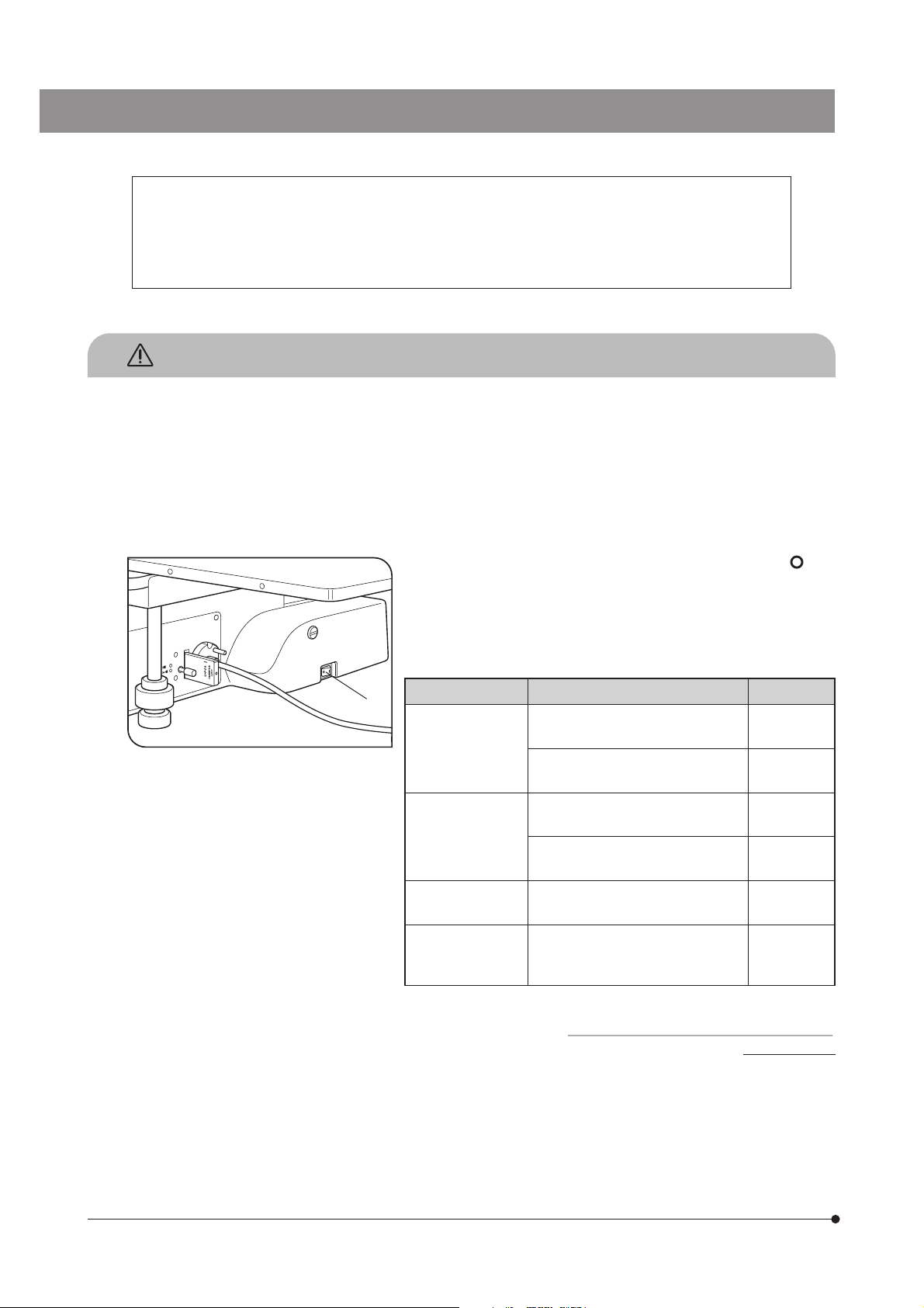
1. Always use the power cord provided by Olympus. If no power cord is
provided, please select the power cord by referring to the section “PROPER
SELECTION OF THE POWER SUPPLY CORD” at the end of this instruction
manual. If the proper power cord is not used, Olympus can no longer
warrant the electrical safety performance of the equipment. Lay out the
power cord at a sufficient distance from the sources of heat such as the
power supply unit/light source and lamp housing to avoid contact with
these heat sources.
2. To avoid potential shock hazard, always set the main switch @ to (OFF)
and disconnect the power cord before replacing the burner or connecting/
disconnecting motorized parts. And since the system contains motorized
parts, do not plug in the power cord until all of the assembly procedures
have completed.
}Always use the lamp bulb or burner supplied by Olympus.
Fig. 1
@
Bulb/Burner Model Average Life
Halogen bulb · 12V100WHAL-L (Long life type)
(PHILIPS 7724)
· 12V100HAL (High-resolution type)
(PHILIPS 7023)
Mercury burner
Xenon burner · UXL-75XB-A
Halogen bulb for
light guide light
source
3. Do not light the mercury or xenon burner while it is not mounted on the
microscope because the UV rays in their light are harmful to your eyes.
The used mercury burner should be disposed of as an industrial waste.
If you cannot dispose of it properly, contact Olympus.
4. The eye point of this microscope can be adjusted in the range between
408 and 560 mm above the desktop surface. Prepare a microscope
desk with an optimum height for the application of the customer.
· USH-103OL
(USHIO)
· HBO103W/2
(OSRAM)
(USHIO)
· JCR12V-100WB
(USHIO)
2000 hrs.
50 hrs.
300 hrs.
300 hrs.
200 hrs.
1000 hrs.
1
MX61/MX61L
5. The desktop surface on which the microscope system is installed should be almost horizontal with a tilting angle of less
than 20’ with the MX61L or less than 1° with the MX61 (to prevent spontaneous displacement of the stage) and rigid.
(The weight of the microscope system with standard module combination is about 53 kg, or 116.6 lbs, with the MX61L and
about 44 kg, or 96.8 lbs, with the MX61.)
}Although these microscopes are designed with excellent vibration resistance, their maximum performance can be
achieved when an anti-vibration bench is used.)
6. The lamp housing surface at the rear of the microscope frame will become very hot during operation. When installing the
microscope, ensure that there are ample free spaces (of more than 100 mm) around and in particular above and below
the lamp housing. Also, the power cord and other cables should be laid out at distances from the microscope because
contact with them may result in their fusion and an electric shock due to it.
7. To avoid a potential shock hazard, make sure that the power cord is safety grounded/earthed.
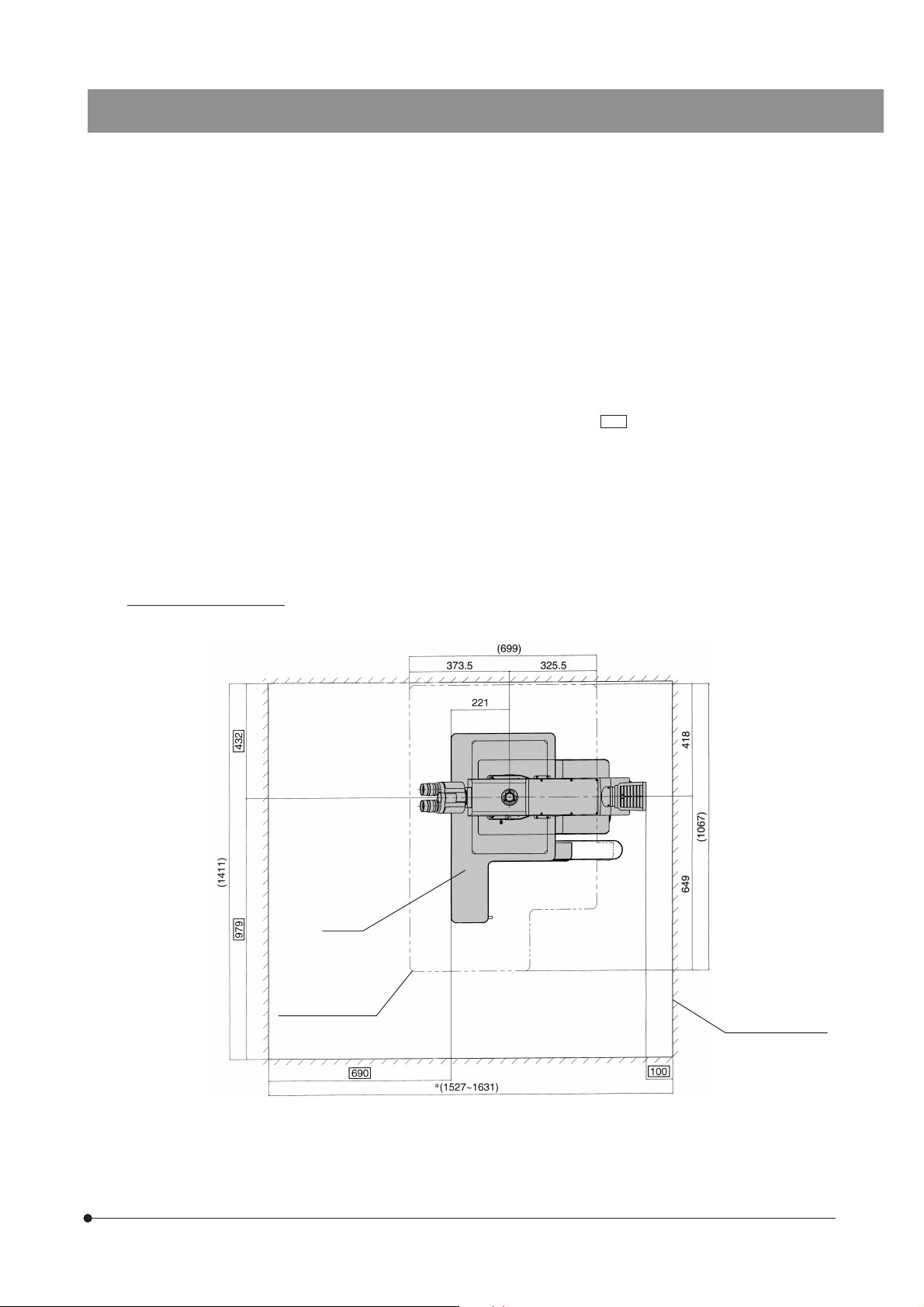
8. To allow each microscope manifest its full performance, reserve an installation space having the minimum dimensions
described below before assembly and installation of the microscope. (Sizes in )
}The dimensions of the area enclosed in alternate long and two short dashes lines indicate the stage movement range.
The dimensions marked * are variable depending on the lamp housing used.
}When maintenance is required, a larger work space can be prepared by changing the observation tube orientation or
moving the stage.
}The following installation space is set according to the SEMI standard guidelines (SEMI S8-1103). It is recommended
that you set the optimum installation space for each customer by referring to the following installation space data as
well as the appearance of the system, eye point height, etc.
MX61L installation space
Unit: mm
MX61L
Stage movement
range
Installation space
2
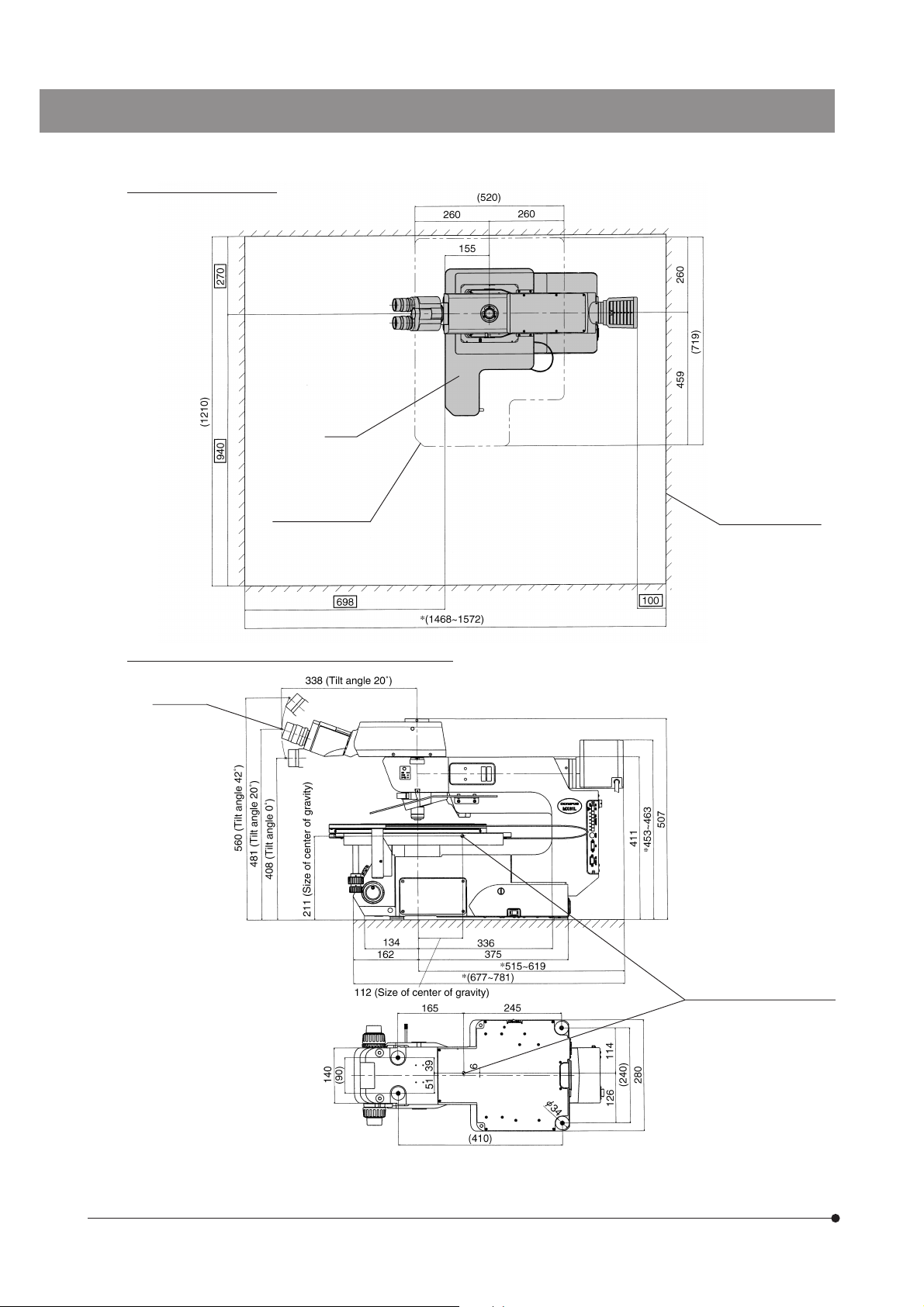
MX61 installation space
MX61
Stage movement
range
Unit: mm
Installation space
MX61L external view, eye point and center of gravity
Eye point
(Bottom view of microscope)
Unit: mm
Position of center of gravity
3
(Note) The center of gravity is an approximate position when the microscope is equipped with the standard module
combination for transmitted light observation. Note that the position is variable depending on the weight of
specimen, position of the stage and other modules used.
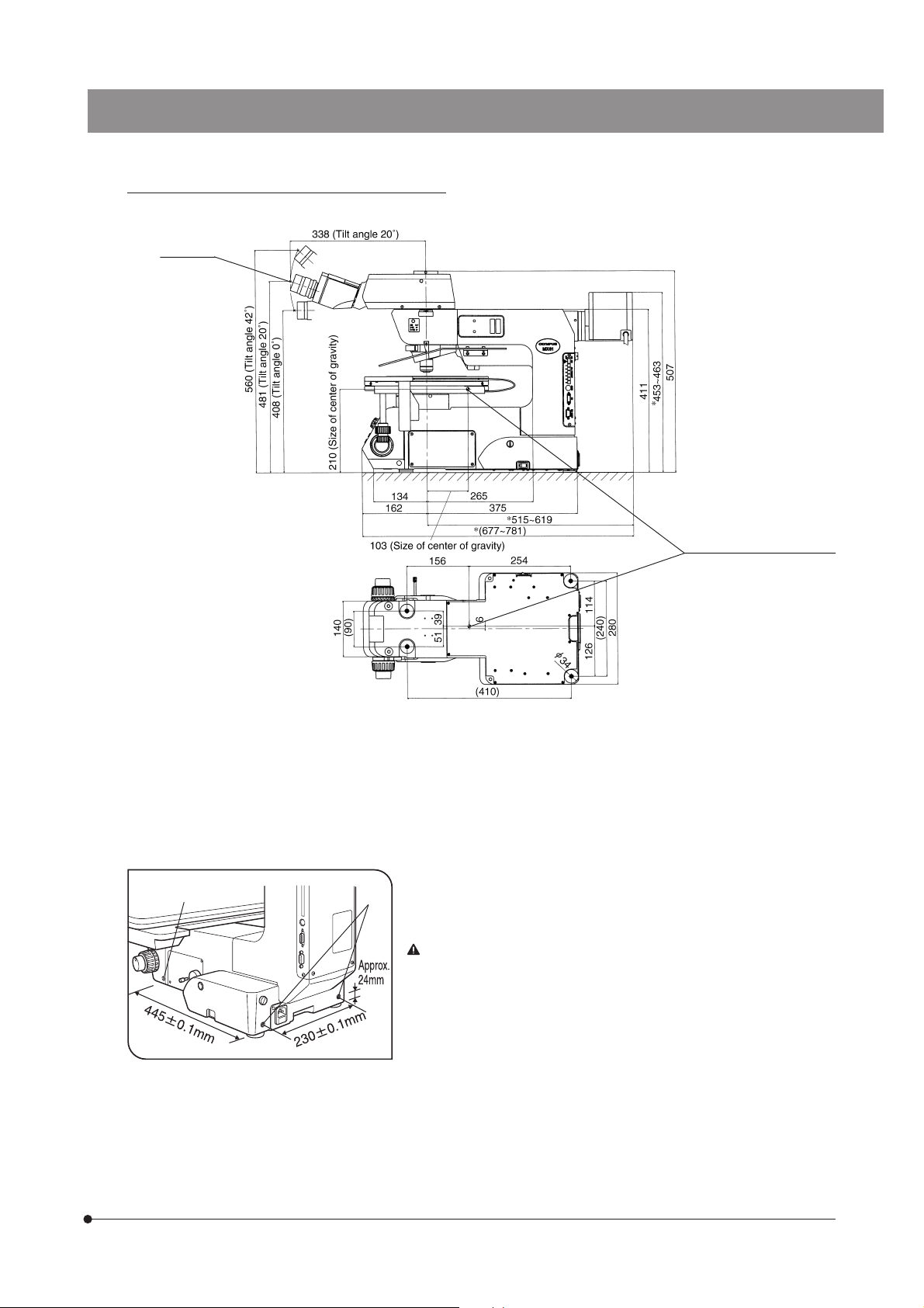
MX61 external view, eye point and center of gravity
Eye point
MX61/MX61L
Unit: mm
Position of center of gravity
(Bottom view of microscope)
(Note) The center of gravity is an approximate position when the microscope is equipped with the standard module
combination for transmitted light observation. Note that the position is variable depending on the weight of
specimen, position of the stage and other modules used.
9. To prevent toppling of the microscope system, keep the total height of the microscope below 1 meter (3.3 ft) when
attachments (including Olympus optional modules and the CCD camera prepared by the customer) are mounted.
10. Each microscope has screw holes (M5, depth 10 mm) for prevention of
@
²
toppling (in the case of an earthquake or microscope imbalance) on the
side panels @ (x 2 holes) and the rear panel ² (x 2 holes). Clamp the
microscope using L-shaped clamps and these screw holes as required.
When clamping the microscope using L-shaped clamps prepared by the customer, be sure to use steel bolts (strength category 12.9) with as long as possible threaded sections (8 mm
or more is recommended).
Fig. 2
4
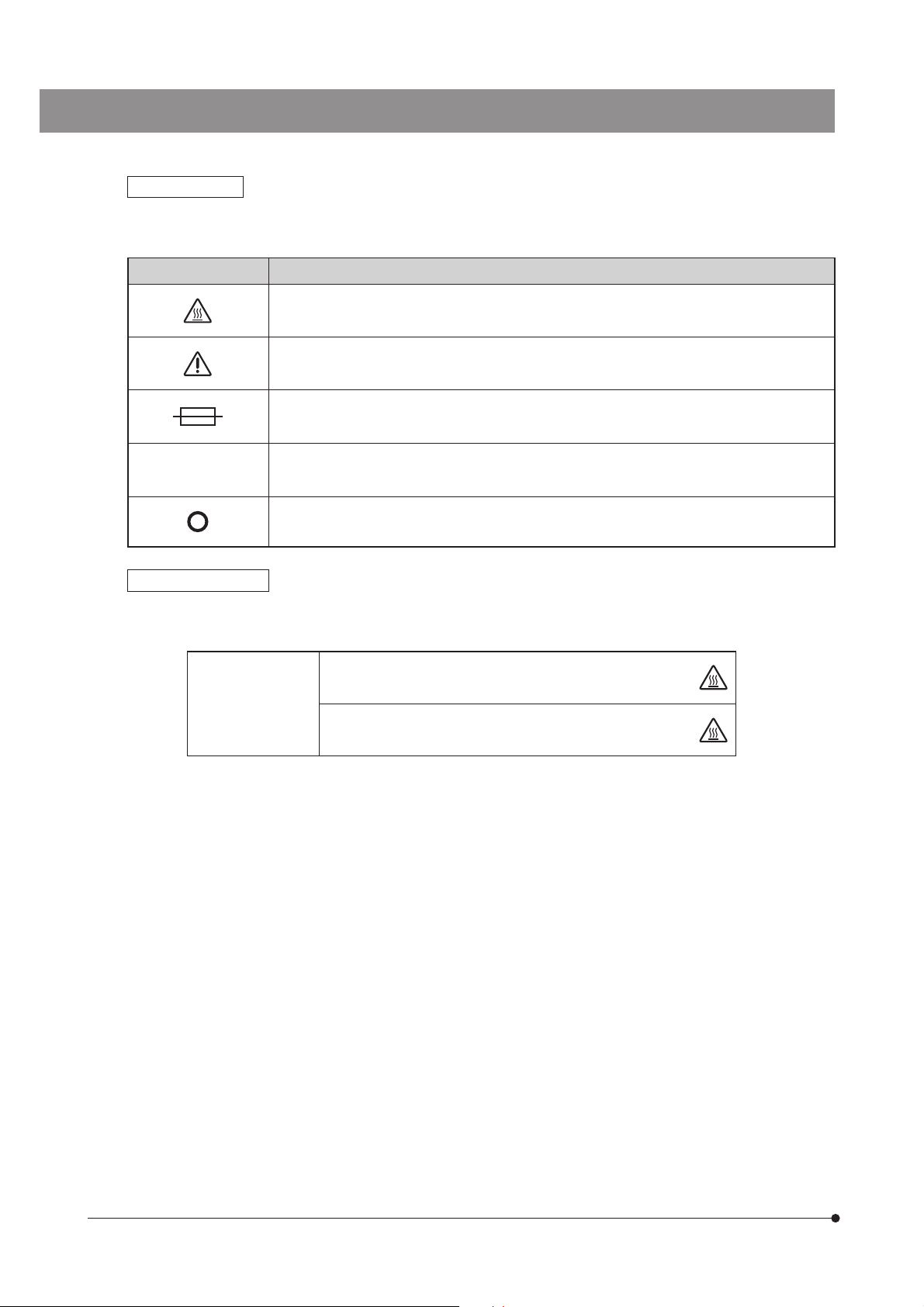
Safety Symbols
The following symbols are found on the microscopes. Study the meaning of the symbols and always use the equipment
in the safest possible manner.
Symbol Explanation
Indicates that the surface becomes hot, and should not be touched with bare hands.
Before use, carefully read the instruction manual. Improper handling could result in injury to the
user and/or damage to the equipment.
Indicates a potential fire hazard; when replacing fuses, be sure replacement fuses are of the
specified rating.
l
Indicates that the main switch is ON.
Indicates that the main switch is OFF.
Caution indications
Caution indications are affixed at parts where special precaution is required when handling and using the microscope.
Always heed the cautions.
Caution indication
positions
Lamp housing/power supply
unit
Light guide light source
(LG-PS2)
[High temperature caution]
[High temperature caution]
5
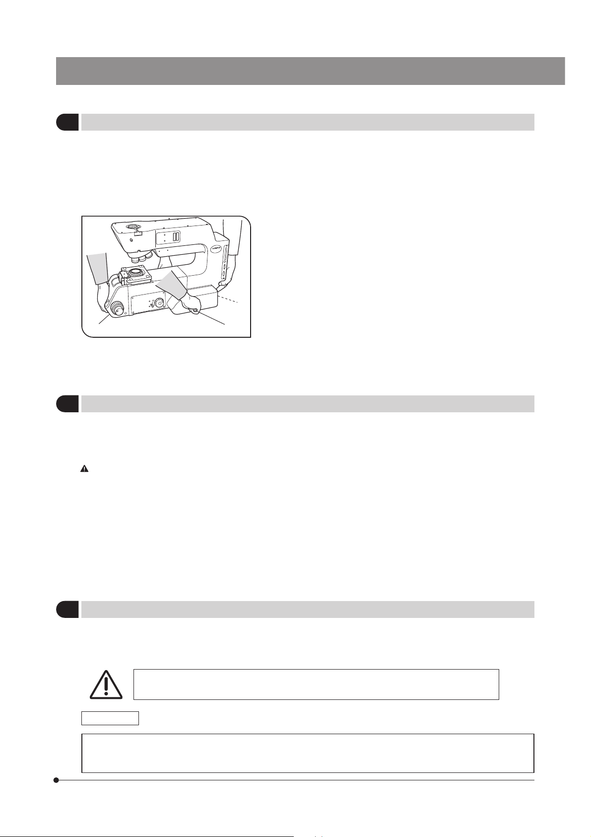
Getting Ready
1
²
Fig. 3
@
MX61/MX61L
1. Do not use the microscope where it is subjected to direct sunlight, high
temperature and humidity, dust or vibrations. (For the operating conditions,
refer to chapter 8, “SPECIFICATIONS “ in the Instruction Manual.)
2. A microscope is a precision instrument. Handle it with care and avoid
subjecting it to sudden or severe impacts. Never attempt to rotate the
motorized revolving nosepiece by hand; otherwise, the gear or other parts
may be damaged.
3. When moving the microscope, detach the observation tube, stage, lamp
housing and specimen to reduce the total system weight, and then
insert the two provided carrying rods @ firmly into the left and right side
panels. Two persons are needed to carry the microscope; one should
hold the front holding section ² and a carrying rod and the other person
should hold the rear holding section ³ and the other carrying rod. Be
sure to move the microscope cautiously. (The microscope frame weight
is about 30 kg, or 66 lbs.)
}After movement, remove the carrying rods, and either have the customer
³
retain them without losing or attach them to the two screw holes on the
rear of the microscope. Attach the provided screw hole caps to the screw
holes left by removing the carrying rods.
#Do not change the position of the microscope by sliding it on the
desktop surface; otherwise, the rubber feet will be damaged.
4. Be sure to attach the transport clamping plate(s) to the stage before
transporting it.
Maintenance and Storage
2
1. To clean the lenses and other glass components, simply blow dirty away using a commercially available blower and wipe
gently using a piece of cleaning paper (or clean gauze).
If a lens is stained with fingerprints or oil smudges, wipe it gauze slightly moistened with commercially available absolute
alcohol.
Since the absolute alcohol is highly flammable, it must be handled carefully.
Be sure to keep it away from open flames or potential sources of electrical sparks –– for example, electrical
equipment that is being switched on or off. Also remember to always use it only in a well-ventilated room.
2. If any part of the equipment (other than glass components) gets dirty, with it with a clean cloth.
If the party is extremely dirty, do not attempt to use organic solvents to clean it; instead, use a soft, lint-free cloth slightly
moistened with a diluted neutral detergent.
3. Never disassemble any part other than instructed of the microscope. This could result in malfunctions or reduced
performance.
4. When not using the microscope, keep it covered with a dust cover. Make sure the lamp housing is cool before covering
the microscope.
5. When disposing of the microscope. Check the regulations and rules of your local government and be sure to
observe them.
Applicable Standards
3
1. These devices are in compliance with or certified by the following standards.
2. Although these devices are designed for use in industrial environments, their full performances may not be manifested if
they are not operated properly. Be sure to handle them properly as instructed in this manual.
These devices are designed for use in industrial environments (Class A devices).
Using them in a residential environment may affect other equipment in the environment.
CE marking
This device complies with the requirements of both directive 89/336/EEC concerning electromagnetic compatibility
and directive 73/23/EEC concerning low voltage. The CE marking indicates compliance with the above directives.
6

FCC
These devices have been subjected to the compliance evaluation of the following FCC regulation:
· FCC Part 15, Subpart B: Radio Frequency Equipment (Commercial and industrial areas)
NOTE: This equipment has been tested and found to comply with the limits for a Class A digital device,
pursuant to Part 15 of the FCC Rules. These limits are designed to provide reasonable protection
against harmful interference when the equipment is operated in a commercial environment. This
equipment generates, uses, and can radiate radio frequency energy and, if not installed and used in
accordance with the instruction manual, may cause harmful interference to radio communications.
Operation of this equipment in a residential area is likely to cause harmful interference in which case
the user will be required to correct the interference at his own expense.
FCC WARNING: Changes or modifications not expressly approved by the party responsible for compliance
could void the user’s authority to operate the equipment.
SEMI
These devices have been subjected to the compliance evaluations of the following guidelines under the S8 Standard.
· S2-0703: Safety Guidelines for Semiconductor Manufacturing Equipment
· S8-1103: Safety Guidelines for Ergonomics Engineering of Semiconductor Manufacturing Equipment
Caution
4
If the microscope is used in a manner not specified by this manual, the safety of the user may be imperiled. In addition,
the equipment may also be damaged. Always use the equipment as outlined in this manual.
The following symbols are used to set off text in this instruction manual.
! : Indicates that failure to follow the instructions in the warning could result in bodily harm to the
user and/or damage to equipment (including objects in the vicinity of the equipment).
# : Indicates that failure to follow the instructions could result in damage to equipment.
} : Indicates commentary (for ease of operation and maintenance).
7
MX61/MX61L
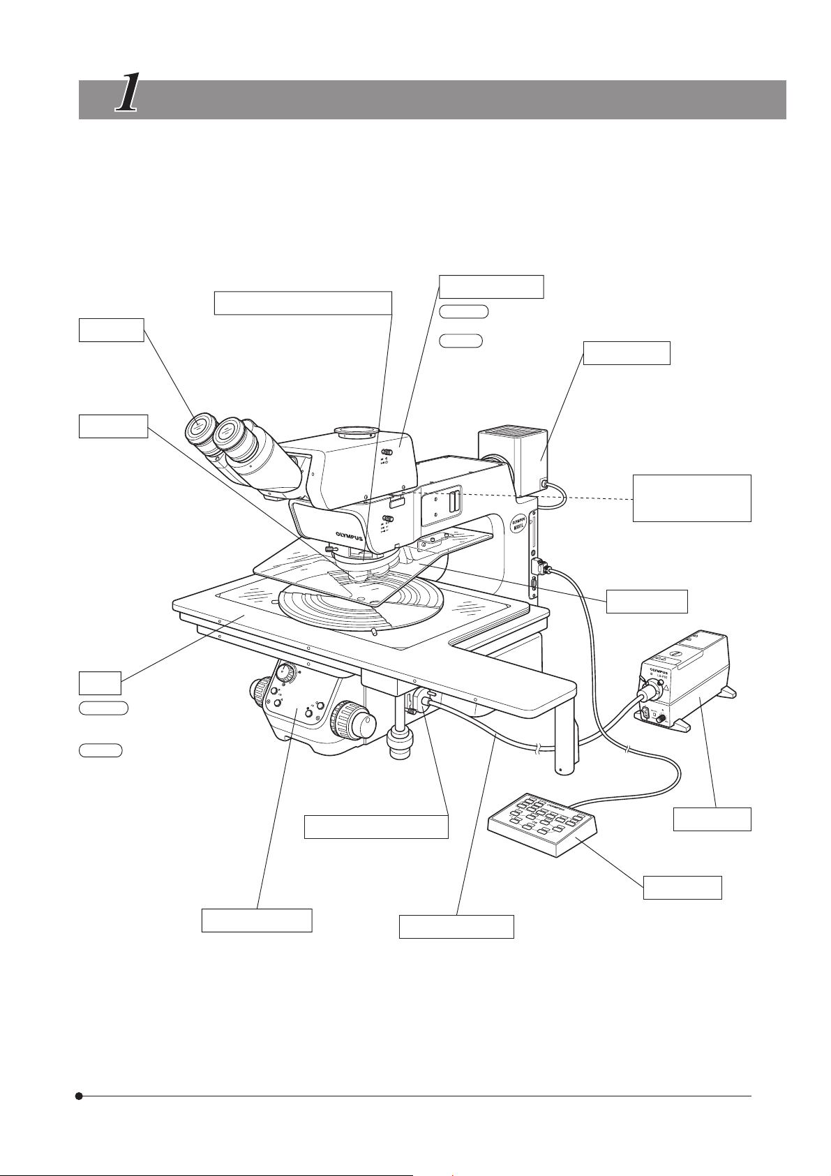
NOMENCLATURE
}The illustration shows the MX61L.
}The modules shown below are examples of those used in a typical system. Certain modules are usable even when they
are not mentioned below. For these modules, refer to the latest catalogues or contact Olympus.
For the modules marked *, refer to their instruction manuals.
Observation Tube
Eyepieces
SWH Series
(FN 26.5)
WHN/WH Series
(FN 22)
Objectives
MPLFLN/
MPLFLN-BD
LMPLFLN/
LMPLFLN-BD
MPLN/
MPLN-BD
UMPlanFl/
UMPlanFl-BD Series
LMPlanFl/
LMPlanFl-BD Series
MPlanApo/
MPlanApo-BD Series
LMPlanApo/
LMPlanApo-BD Series
MPlan/MPlan-BD Series
Motorized Revolving Nosepiece
U-D5BDREMC
U-D6REMC
U-P5REMC
MX61L
MX-SWETTR (FN 26.5)
MX61
MX-SWETTR (FN 26.5)
U-SWTR-3 (FN 26.5)
U-TR30-2 (FN 22)
U-BI30-2 (FN 22)
Lamp Housing
U-LH100-3/LH100L-3 (Halogen bulb)
U-LH100HG/LH100HGAPO
(Mercury burner)
U-LH75XEAPO (Xenon burner)
(Note) The MX-HGAD adapter is
required for the mercury
burner and xenon burner.
Intermediate Attachment
(Only one of the following can be attached.)
U-EPA2 *
U-CA/ECA *
MX-AFSU *
U-CFU *
Breath Shield
MX-BSH
MX-BSH-ESD
Stage
MX61L
MX-SIC1412R2 (Transmitted light/
reflected light observation model)
MX61
MX-SIC8R (Transmitted light/
reflected light observation model)
MX-SIC6R2
(Reflected light observation only)
MX-SIC6A
(Reflected light observation model)
Microscope Frame
MX61L-F
MX61-F
Transmitted Light Module
MX-TILLA
MX-TILLB
Flexible Light Guide
LG-SF *
Light Source
LG-PS2 *
Hand Switch
U-HSTR2
8
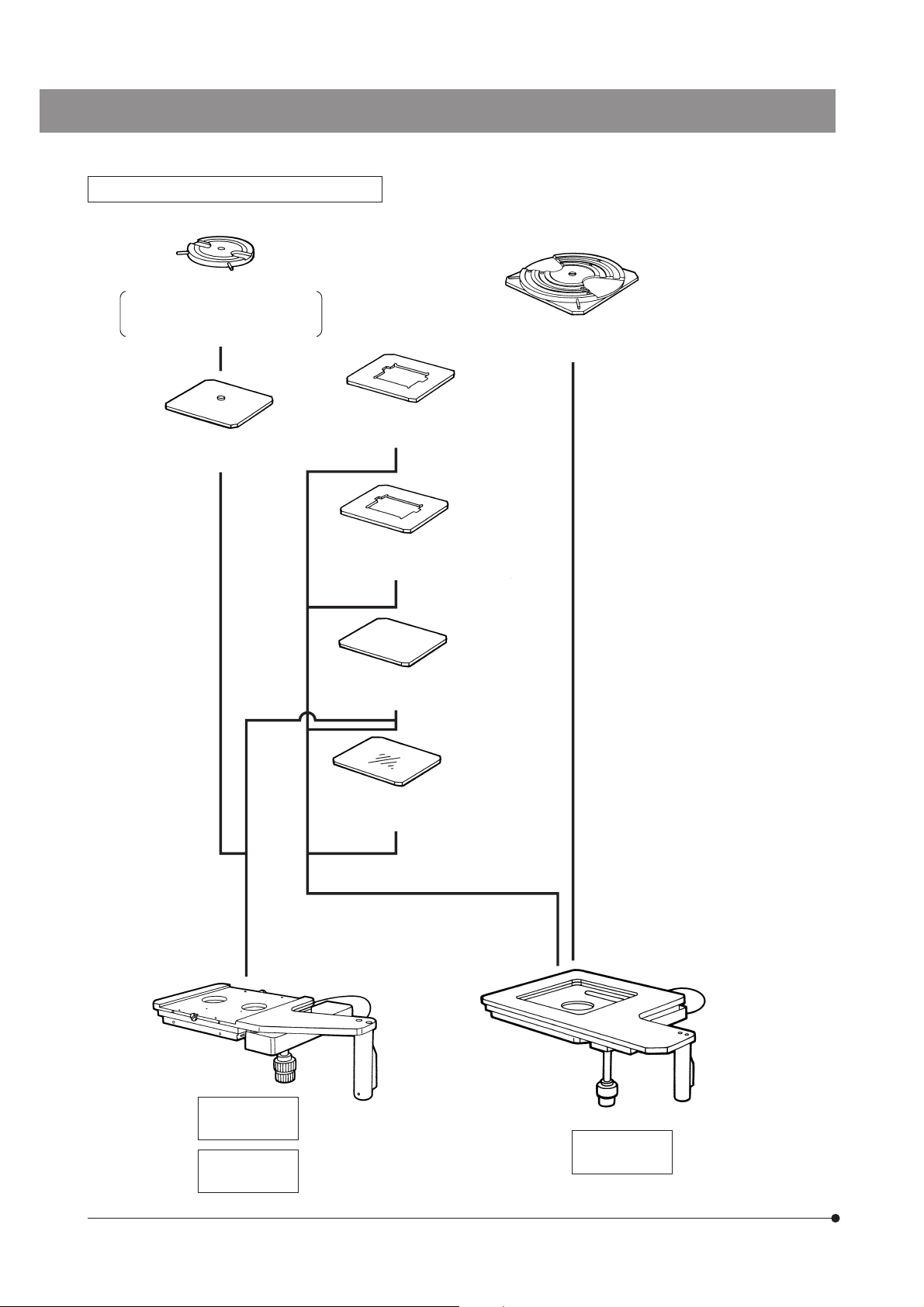
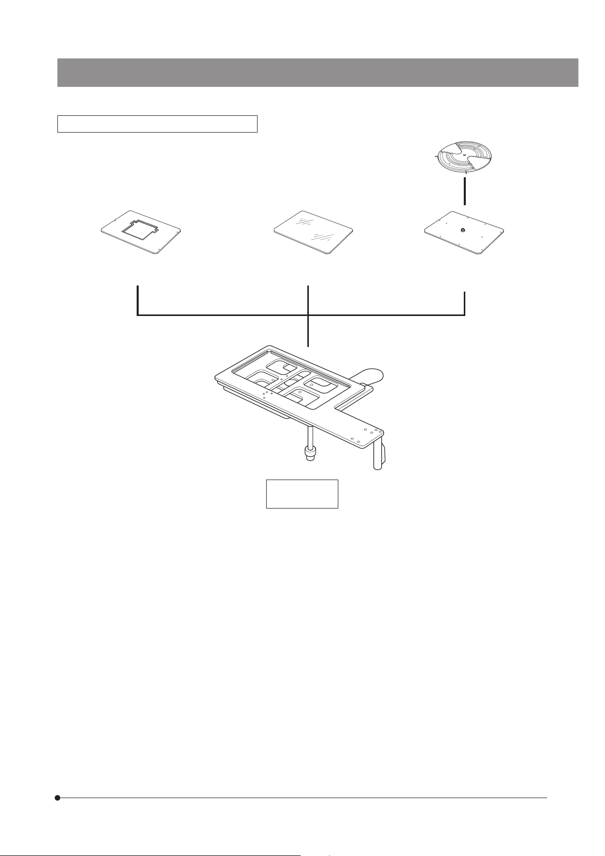
Stage and Holder System for the MX61
Rotary Wafer Holder
BH2-WHR43 (For 3-4 inch wafers)
BH2-WHR54 (For 4-5 inch wafers)
BH2-WHR65 (For 5-6 inch wafers)
5-Inch Mask Holder
Rotary Wafer Holder Plate
BH3-WHP6
4-Inch Mask Holder
Rotary Wafer Holder Plate
MX-WHPR86 (For 6-8 inch wafers)
BH3-MH5
BH3-MH4
6x6-Inch Stage
MX-SIC6A
6x6-Inch Stage
MX-SIC6R2
Black Plate
BH3-SP6
Glass Plate
BH3-SPG6
8x8-Inch Stage
MX-SIC8R
9
Stage and Holder System for the MX61L
MX61/MX61L
6-Inch Mask Holder
MX-MH6
Glass Plate
MX-SPG1412
14x12-Inch Stage
MX-SIC1412R2
Rotary Wafer Holder for 8-inch
and 12-inch wafers
MX-WHPR128
10
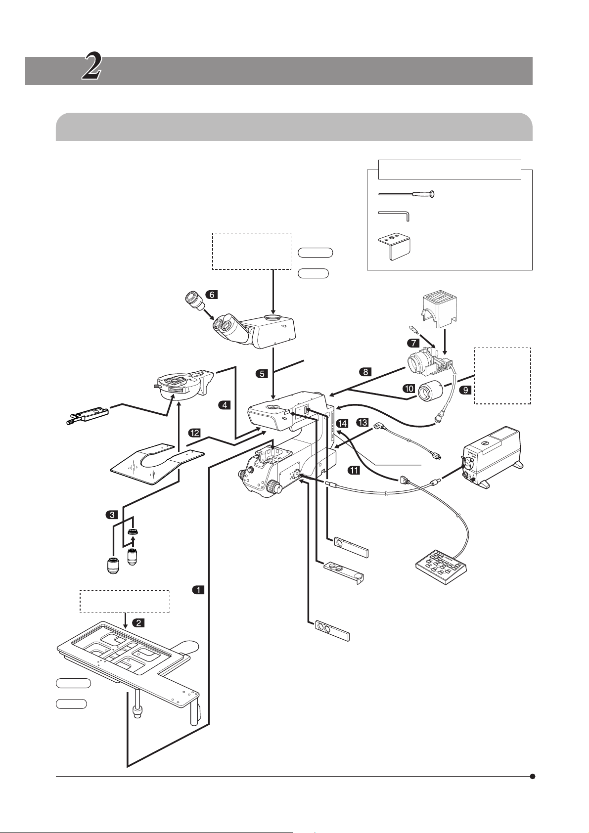
ASSEMBLY
2-1 Assembly Diagram
}The diagram below shows where the various modules should be
mounted. Study the assembly instructions for only the modules to be
employed.
# When assembling the equipment, make sure that all parts are free
of dust and dirt and avoid scratching any parts or touching glass
surfaces.
TV system
Photomicrographic
system
Eyepieces
SWH Series
WHN Series
Motorized revolving
nosepiece
U-D5BDREMC
DIC slider
U-DICR
U-DICRH
U-DICRHC
Breath shield
MX-BSH
MX-BSH-ESD
U-D6REMC
U-P5REMC
Observation tube
MX61L
MX-SWETTR
MX61
MX-SWETTR
U-SWTR-3
U-TR30-2
U-BI30-2
Intermediate attachment
(Only one of the following
can be attached.)
U-EPA2
U-CA/ECA
MX-AFSU
U-CFU
Halogen bulb
12V100WHAL-L
12V100WHAL
(Provided with the microscope frame)
AF connector
Tools Used
Allen screwdriver (3 mm)
Allen wrench (3 mm)
Tool holder
100 W halogen
lamp housing
U-LH100-3
U-LH100L-3
High-intensity
lamp housing
U-LH75XEAPO
U-LH100HG
U-LH100HGAPO
Adapter
MX-HGAD
Power cord
Note 2)
Brightfield/
darkfield
objective
(See pages 9 and 10.)
Stage
MX61L
MX-SIC1412R2
MX61
MX-SIC8R
MX-SIC6R2
MX-SIC6A
Holders
Brightfield
objective
adapter
BD-M-AD
Brightfield
objective
Microscope frame
MX-61L-F
MX61-F
(Transmitted light
module)
MX-TILLA
MX-TILLB
Light guide
LG-SF
Analyzer
U-AN360-3
Filters
U-25ND6-2
U-25ND25-2
U-25LBD
U-25IF550, etc.
Polarizer
U-PO3
Hand switch
U-HSTR2
Note 1)
Note 1) Exclusive connector for the U-HSTR2 hand switch. To prevent mal-
function, do not connect other modules.
Note 2) Exclusive connector for the MX-AFCB control box for use with an
Olympus active AF unit. To prevent malfunction, do not connect
other modules.
}The tools used can be stored in the holes on the tool holder provided
with the microscope frame. Use the double-sided adhesive tape of the
tool holder to attach it to a position that does not hinder operation.
!Do not attach the tool holder anywhere near the bottom of the lamp
housing since it generates high-temperature heat.
Light source
LG-PS2
11
MX61/MX61L
2-2 Detailed Assembly Procedures
!The system contains motorized parts. Do not plug in the power cord until all of the assembly procedures have
completed.
@
Fig. 4
Fig. 5
³
²
|
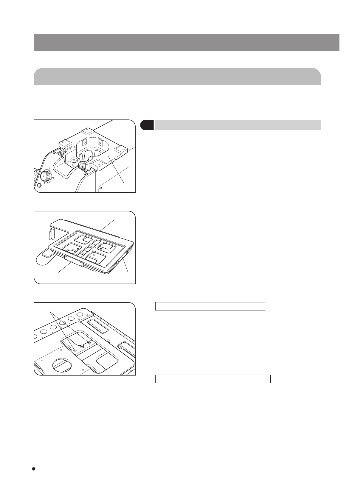
Attaching the Stage
1
1. Using the Allen wrench (3 mm), remove the transport clamping plate @
from the rear edge of the stage. (Fig. 5) The removed screws should be
used to clamp the stage when attaching it.
}With the MX-SIC6R2/SIC6A, the mounting screw holes are invisible un-
less the upper stage is displaced. It is therefore necessary to remove the
transport clamping plates from the front and rear of the stage.
#Two transport protection sheets are placed in the gaps of the MX-
SIC6A/SIC6R2/SIC8R stage. Be sure to remove them before using
the system.
2. While holding the stage so that the coarse adjustment grip and X-axis/
Y-axis knobs are on the right, gently place the stage on the stage holder
². Using the Allen screwdriver or Allen wrench, tighten the four screws
temporarily.
3. Remove the transport clamping plate(s) from the front ³ and side (MXSIC1412R2 only) | of the stage, move it to the rearmost position and,
after confirming that the stage and arm do not interfere with each other,
tighten the four screws firmly. (Fig. 5)
# The clutch and belt may stick together and prevent smooth operation
of the release function if the stage has not been moved for a long
time. If this phenomenon occurs, take the remedial action described
in page 22 in the instruction manual.
(Figs. 4 & 5)
ƒ
Fig. 6
Attaching the Y-Stroke Limit Stopper (Fig. 6)
}When the MX-SIC1412R2 stage is used in transmitted light observation
(possible only when the MX-TILLA is used), it is required to attach this
stopper for limiting the Y-axis stroke to 10 inches in order to prevent
interference between the stage and the projected part of the condenser.
1. Place the stage upside down and remove both transport clamping plates.
2. Move the stage and insert the stopper, provided with the stage, into the
two stopper holes ƒ on the center stage.
3. Attach only the front transport clamping plate and then attach the stage.
Caution Before Transporting the Stage (Fig. 5)
Before transporting the stage, be sure to attach the transport clamping
plates @³| and package the stage carefully. Do not transport the stage
when it is attached to the microscope frame or inadequately packaged.
Otherwise, the stage will be damaged.
12

²
|
Fig. 7
Fig. 8
@
³
Attaching the Holders
2
# Attach a holder in the direction so that the notch on the holder’s
side faces left. The adjustment of the levelness is performed in this
direction.
Attaching the Wafer Holder (Fig. 7)
1. Insert the wafer holder plate @ into the stage, one edge first.
2. Push the wafer holder plate from above to make sure that it sits correctly
with no tilt.
3. Using a flat-blade precision screwdriver, clamp the plate by tightening
the holder clamping screw ² on the left side of the stage.
# The levelness of the holder is adjusted by the heights of the three
screws on the back side of the stage. Do not push positions near
the holder, for this may tilt the holder.
Attaching the Mask Holder (Fig. 8)
1. Carefully place the mask holder ³ on the stage surface, making sure
that it sits correctly with no tilt.
2. Using the precision screwdriver, clamp the plate by tightening the holder
clamping screw | on the left side of the stage.
Attaching the Black Plate/Glass Plate
Carefully place the plate on the stage surface, and tighten the holder
clamping screw on the left side of the stage.
# When attaching the glass plate, do not tighten the clamping screw
excessively as the glass plate may break. Tighten to the extent that
the glass plate does not rattle noticeably when attached.
(Figs. 7 & 8)
13
@
Fig. 9
@
Adjusting the Levelness of Holder Plate (Fig. 9)
The levelness of the stage travel (movement) and the top surface of the
wafer holder have been adjusted at the factory. If finer adjustment is
required or when using a holder from a manufacturer other than Olympus,
apply drops of alcohol on screws @ to loosen the screw lock, then
adjust the heights of the screws by inserting a flat-bladed screwdriver
from below.
#The maximum loads of the stages including the holders are as
follows.
MX-SIC8R/MX-SIC6R2/MX-SIC6A : 2 kg (4.4 lbs.)
MX-SIC1412R2 : 3.5 kg (7.7 lbs)

MX61/MX61L
Fig. 10
Fig. 11
@
@
Attaching the Objectives
3
#Never attempt to rotate the motorized revolving nosepiece by hand.
Rotating by hand may cause malfunction or damage.
Remove the cap from each objective mount hole.
1. Following the order of numbers 1 to 5 or 6 indicated on the objective
mount thread @, screw objectives into the objective mount threads by
starting with the objective with the lowest power.
#The rotation of the revolving nosepiece can be made smooth by
mounting objectives uniformly in all of the nosepiece positions.
Therefore, the objectives that are not used frequently should also
be mounted.
Be sure to attach the caps to the unused objective mount hole.
Using the Brightfield Objective Adapter
When mounting a brightfield objective on a revolving nosepiece designed
for brightfield/darkfield objectives, mount each objective by means of the
BD-M-AD objective adapter.
.
Attaching the Motorized Revolving Nosepiece
4
# It is only the U-D5BDREMC, U-D6REMC or U-P5REMC revolving nose-
piece that can be used.
#Lower the stage far enough to ensure that the objectives do not
touch the stage when mounting the revolving nosepiece.
#Slide the revolving nosepiece all the way into the dovetail mount
until it stops.
#The revolving nosepiece is a heavy module. Take care not to drop it
during mounting.
1. Loosen the revolving nosepiece clamping screw @ using the provided
Allen screwdriver, slide the revolving nosepiece all the way into the
dovetail mount until it stops, and tighten the clamping screw @.
#If the clamping screw is tightened without sliding the revolving
nosepiece all the way, the clamping section may be deformed,
the revolving nosepiece may become irremovable, and the connector
contact failure may occur also.
2. Set the DIP switches for the mounted revolving nosepiece (see page 20
for the setup method).
(Fig. 10)
(Fig. 11)
@
Fig. 12
Attaching the Observation Tube
5
1. Using the provided Allen screwdriver, fully loosen the observation tube
clamping screw @.
2. Insert the circular dovetail mount at the bottom of the observation tube
into the observation tune mount on the top surface of the arm.
3. Clamp the observation tube by tightening the clamping screw @.
(Fig. 12)
14

Fig. 13
@
²
Attaching the Eyepieces
6
Fit and insert gently an eyepiece into each eyepiece sleeve.
# When using the U-BI30-2 binocular observation tube, an eyepiece
incorporating the eyepiece micrometer disk cannot be used.
# When using a finder eyepiece or an eyepiece with micrometer disk,
insert into the right eyepiece sleeve.
Insert the eyepiece so that its positioning pin @ fits into the groove
² at the bottom of the eyepiece sleeve.
# The super-widefield observation tube has the eyepiece positioning
grooves. Be sure to fit the positioning pins into the grooves on both
eyepiece sleeves when mounting the eyepieces.
(Fig. 13)
@
²
Fig. 14
Fig. 15
ƒ
³
…
Attaching the Halogen Bulb
7
}The applicable halogen bulbs are the 12V100WHAL-L long-life bulb
(PHILIPS 7724) and the 12V100WHAL high-intensity bulb (PHILIPS 7023).
1. Using the Allen screwdriver provided with the microscope, fully loosen
the clamping screw @ on the top of the lamp housing.
2. Lift the lamp housing ² to remove.
3. Tilt the lamp socket ³ by 90° in the direction of the arrow.
4. While holding down the lamp clamping lever |, hold the halogen bulb
ƒ by means of a piece of gauze, and insert the pins … all the way into
the pin holes †.
Return the lamp clamping lever to the original position to clamp the bulb.
!Do not touch the bulb directly with bare hand. If fingerprints are
attached on it, wipe thoroughly with a soft cloth to prevent the
service life from dropping and the bulb from cracking.
5. Fit the lamp housing ² from above and tighten the clamping screw @
while pushing down the screw by force. (Fig.14)
!Bulb replacement during use or right after use
The bulb. lamp housing and areas near these will be extremely hot
during and right after use.
After setting the main switch to “ ” (OFF) and unplugging the
power cord from the power outlet, allow the old bulb and lamp
socket to cool before replacing the bulb with a new one of the
designated type.
(Figs. 14 to 16)
15
|
†
Fig. 16

MX61/MX61L
³
³
Fig. 17
Fig. 18
Fig. 19
ƒ
@
²
|
²
@
|
Attaching the Lamp Housing
8
1. Fit the lamp housing @ all the way into the lamp housing mount on the
rear of the microscope arm.
!Attach the lamp housing so that the heat radiating fins ² face upward.
To prevent a fire hazard, reserve ample spaces above, below and on
the rear of the lamp housing.
2. After fitting the lamp housing @, tighten the two clamping screws ³
using the Allen screwdriver provided with the microscope.
#Do not tighten the screws too much, as this may deform the lamp
housing mount.
3. Connect the connector | of the lamp housing to the connector ƒ on
the rear of the arm.
Attaching the Mercury Burner
9
}For the xenon burner, attach the burner, reset the hour counter and
connect the cables as described in the manual provided with the light
source in use.
1. Loosen the socket clamping screw @ using the Allen screwdriver.
2. Hold the upper section of the lamp housing and pull it upward to remove
the socket section.
#To prevent malfunction, do not hold the lamp housing by the
centering knobs ².
3. Place the socket section upside down as shown in Fig. 19.
}The lamp housing is equipped with the holder for transportation in the
factory shipment condition or with an old burner when the burner is
replaced. Remove the holder or old burner by loosening the two burner
holding screws ³.
4. Attach the + (positive) pole of a specified mercury burner | to the fixed
mount on the upper side, then the - (negative) pole to the mount on the
lower side.
#Be sure to use the USH-103OL (USHIO) or the HBO103W/2 (OSRAM)
mercury burner.
# Be careful and avoid leaving fingerprints or contaminants on the mercury
burner. Otherwise, there is a danger of explosion due to distortion of
glass caused by the stains. If the burner is contaminated, clean it by
wiping gently with gauze slightly moistened with absolute alcohol.
5. Attach the socket section with burner to the original position and tighten
the socket clamping screw @.
#Align the external edges of the lamp housing with those on the
socket section, and push the lamp housing straight downward.
!Attach the lamp housing so that the heat radiating fins face upward.
To prevent a fire hazard, reserve ample spaces above, below and on
the rear of the lamp housing.
!Do not light the mercury burner while it is not mounted on the
microscope because the UV rays in its light are harmful to your
eyes.
#The UV rays in the light of the mercury burner may damage the
specimen if this is sensitive to UV rays.
(Figs. 18 to 23)
(Fig. 17)
16

@
²
Resetting the Burner Hour Counter
1. Press the center section @ of the reset switch ² on the front panel to
reset the counter reading to “000.0”.
}The hour counter shows elapsed time in hours. The service life of a
mercury burner is 300 hours. For safety’s sake, replace the burner when
the hour counter reads “300.0”.
Fig. 20
Fig. 21
! Mercury Burner Replacement
1. The service life of the mercury burner is 300 hours. In order not to
impair the safety of the equipment, replace the burner when it has
been used for 300 hours (USH-103OL, HBO103W/2). The burner
may crack if used beyond the specified life time.
When the end of the burner’s service life is near, flickering is likely
to increase. It is therefore recommended to replace the burner
according to the purpose of observation.
* This value assumes light cycles composed of 2 hours of lighting
and 30 minutes of extinction (with the USH-103OL). Do not turn it
on and off at a shorter cycle than the above, for this will shorten the
service life of the burner.
2. Before replacing the burner, wait at least 10 minutes, or until the
burner and lamp housing have cooled down, after turning the burner
off. Before removing the burner, confirm that the main switch is “ ”
(OFF) and unplug the connecting cord from the output connector
of the power supply.
Refer to page 16 for details on replacement procedure.
3. After replacing the burner, reset the hour counter to “000.0” as outlined above.
17

Setting Up the Power Supply Unit for Mercury Burner
MX61/MX61L
³
Fig. 22
|
Fig. 23
²
ƒ
@
@
²
³
CAUTION This operation should be performed after completing the
attachment of the lamp housing described in the next
section.
!Cables and cords are vulnerable to bend or twist. Do not apply
excessive force to them.
!Make sure that the main switch is set to “ ” (OFF) before connecting
cords and cables.
!Always use the power cord provided by Olympus. If no power cord is
provided, please select the power cord by referring to the section “PROPER
SELECTION OF THE POWER SUPPLY CORD” at the end of this instruction
manual. If the proper power cord is not used, Olympus can no longer
warrant the electrical safety performance of the equipment.
1. Make sure that the voltage and frequency of the input power are within
the ranges indicated on the name plate @.
(100 V systems can be used with voltages in the 100 to 120 V range and
200 V systems can be used with voltage in the 220 to 240 V range, both
with frequencies of 50 to 60 Hz.)
2. Plug the connection cord to the connector ² on the power supply unit.
3. Attach the power cord to the power input connector ³ of the power
supply unit, and plug the power plug | of the power cord into the wall
power outlet ƒ.
!Always ensure that the grounding terminal is safety grounded/
earthed. If the equipment is not grounded/earthed, Olympus can no
longer warrant the electrical safety performance of the equipment.
Attaching the High-Intensity Light Source
10
Lamp Housing
(Fig. 24)
Fig. 24
Fig. 25
@
1. Fit the MX-HGAD adapter @ all the way into the lamp housing mount
on the rear of the microscope arm, tighten the two clamping screws ²
using the Allen screwdriver.
2. Fit the mount section of the high-intensity lamp housing into the adapter,
confirm that the lamp housing is not tilted, and clamp the two clamping
screws ³ using the Allen screwdriver.
!When the high-intensity light source is used, the brightness becomes
too high during brightfield observation. Be sure to install the provided
ND filter (ND0.5*) in the brightfield observation light path.
* If the brightness after insertion of the ND0.5 filter is too low, use a different
ND filter (ND3 and ND6 filters available as options).
}The ND0.5 filter provided with the lamp housing can be mounted only by
the Olympus qualified personnel.
Connecting the Hand Switch (U-HSTR2)
11
!To prevent damage to the internal circuitry, always make sure that the
power cord is unplugged and the main switch is set to “ ” (OFF)
before connecting or disconnecting the hand switch.
Plug the hand switch connecting cable into the socket @ on the right
side of the microscope frame.
(Fig. 25)
18

²
³
|
Fig. 26
@
Attaching the Breath Shield
12
(MX-BSH or MX-BSH-ESD)
1. Attach the two breath shield mounting brackets @ on the breath
shield ² using the provided screws (shorter ones). For the present,
tighten the screws temporarily using the Allen screwdriver. (If they
are attached completely, it becomes impossible to attach the breath
shield to the microscope frame.)
2. Align the attaching holes | on the mounting brackets with the breath
shield screw holes ³ on the microscope, and clamp using the provided
screws (longer ones).
3. Now tighten the screws that have been secured temporarily in step 1 above.
# Do not tighten the screws excessively to prevent the breath shield
from cracking.
(Fig. 26)
³
Fig. 27
…
²
Fig. 28
|
ƒ
@
Connecting the Power Cord
13
!Cables and cords are vulnerable to bend or twist. Do not apply
excessive force to them.
!Make sure that the main switch @ is set to “ ” (OFF) before
connecting cords and cables. (Fig. 27)
!Always use the power cord provided by Olympus. If no power cord is
provided, please select the power cord by referring to the section “PROPER
SELECTION OF THE POWER SUPPLY CORD” at the end of this instruction
manual. If the proper power cord is not used, Olympus can no longer
warrant the electrical safety performance of the equipment.
1. Connect the power cord plug ² to the AC receptacle ³. (Fig. 28)
!Connect the provided power cord correctly and ensure that the
grounding terminal of the power supply and that of the 3-conductor
wall outlet are properly connected. If the equipment is not grounded/
earthed, Olympus can no longer warrant the electrical safety performance of the equipment.
2. Connect the power cord plug | to a 3-conductor power outlet ƒ.
Fuse Replacement
1. Always set the main switch @ to “ ” (OFF) and disconnect the power
cord before replacing fuses.
2. When the power cord plug is disconnected from the receptacle on the
microscope frame, the fuse cassette … becomes visible. (Fig. 28).
3. Apply a flat-blade screwdriver in turn to the claws on both sides of the
fuse cassette to pull the fuse cassette outward.
4. Replace the two fuses and return the fuse cassette to its original position.
(Figs. 27 to 29)
(Fig. 29)
19
Applicable Fuses : T3.15A(H)250V
(LITTELFUSE 2153.15)
!Use of improper fuse type could result in a fire.
Fig. 29

MX61/MX61L
Fig. 30
Setting the DIP Switches and
14
PRESET Switches
DIP Switch Setting (Fig. 30)
#Confirm the correct connections before proceeding.
}Set the main switch of the microscope to “ ” (OFF) before setting the
DIP switch @.
The DIP switch settings are read and entered at the moment the
microscope is turned ON.
#Be careful not touch the internal circuit boards when setting the DIP
switches. Otherwise, the internal circuitry may be damaged by static
electricity. Since the human body is charged with a small amount of
static electricity, discharge it from your body before proceeding to
the setup. This is done by lightly touching any metallic object.
Function Setting Result
Revolving
nosepiece type
(Number of holes)
Aperture iris diaphragm
control button setting
Glare prevention during
objective switching
(Darkfield observation)
U-D5BDREMC/P5REMC
U-D6REMC
Setting enabled.
Setting disabled.
Glare prevention
No glare prevention
DIP Switches
1234
OFF
ON
(Fig. 30)
OFF
ON
OFF
ON
: Factory setup.
20

21
AS (Aperture Stop) PRESET Switch Setting (Fig. 30)
}The AS PRESET switches ² are used to preset the AS (aperture stop) value for each objective so that the opening of the
aperture iris diaphragm can be switched in an interlocked operation to the objective switching.
In the darkfield observation, the aperture iris diaphragm is fixed automatically at the open position.
The positions of the AS PRESET switches can be changed while the main switch is set to “ ” (ON).
Setting the AS values
Insert a flat-blade precision screwdriver into the AS PRESET switch ² corresponding to the number of the objective
mount thread accommodating the desired objective, and turn the switch so that its arrow points the desired AS value.
(See Table 1 for the recommended values.)
AS interlocking
· When using the U-HSTR2 hand switch:
When the objective switching button on the hand switch is pressed, the objective is switched and, at the same time, the
AS value is set to the value set for the new objective. If the AS switch position is changed while the main switch is set to
“ ” (OFF), the new AS value will be applied to each objective after the main switch is set to “ ” (ON).
· When using computer control through the serial interface (RS-232C):
When the request command (1OBA n) is input, the objective is switched at the same time as change of the AS
value to the set value.
Table 1 Recommended Settings of the AS PRESET Switches (Positions marked ¦)
(Note) The factory settings are all 0.
AS
PRESET
Switch
Setting
Open AS Close AS
MPLFLN/UMPlanFl Series
MPLFLN-BD/UMPlanFl-BD/MPlanFl-BD Series
5X 10X 20X 50X 100X 5X 10X 20X 50X 100X 150X 250X
0
1
2
3
¦¦
4
5
6
7
8
9
A
B
C
D
E
F
¦¦¦
AS interlocking not available
¦
LMPLFLN/LMPlanFl Series
LMPLFLN-BD/LMPlanFl-BD Series
¦
¦¦
Not used
Not used
UMPlanApo Series
UMPlanApo-BD
Series
¦
¦
¦
(Notes) · The recommended AS values correspond to between 70% and 80% of the objective
pupil diameters. As a result, if the aperture iris diaphragm is stopped down below the
recommended value (toward “D”), the observation image will be glaring.
· When using an objective not in the objective list, set the objective pupil diameter at 70%
to 80%.
· Setting “0” inhibits the interlocked change of the AS value. Although the switch setting is
set at “0", the AS value becomes open when brightfield observation is switched to darkfield
observation. On the contrary, the AS value remains open when darkfield observation is
switched to brightfield observation.
· With fluorescent light observation, set the AS value to “1” (AS open).

MX61/MX61L
²
@
Fig. 31
Fig. 32
†
…
Centering the Reflected Light
15
Aperture Iris Diaphragm
1. Set the light path selector knob @ to “BF”. (Fig. 31)
2. Press the objective switching button ³ or | (or switch the objective from
the hand switch or computer), engage the 10X objective in the light path,
and bring the specimen into approximate focus.
#To facilitate observation of the aperture iris diaphragm image, it is
recommended to use a highly reflective specimen such as a mirror.
3. Remove the eyepiece and, while looking into the eyepiece sleeve, press
the aperture iris diaphragm open/close button ƒ so that the aperture iris
diaphragm image is visible. (Fig. 34)
4. If the center of the aperture iris diaphragm is deviated, use the Allen
screwdriver provided with the microscope to loosen (by 1 turn or 2) the
aperture iris diaphragm clamping screw ². Then insert the Allen screwdriver into the aperture iris diaphragm centering screws …† and turn the
screws to center it.
5. Tighten the aperture iris diaphragm clamping screw ².
(Figs. 31 to 34)
³
|
Aperture iris diaphragm image
ƒ
Fig. 33
70%
30%
Fig. 34
22

2-3 Modules Installed by Olympus
The modules described in the following sections are installed and adjusted by Olympus. The user
should not install and/or adjust them.
# When installing the modules, the personnel of Olympus must take caution not to put fingerprints or
scratches on them.
Transmitted Light Module (MX-TILLA/TILLB)
1
³
@
²
†
‡
Š
|
1. Remove the stage.
2. Insert one of the provided clamping screws (AB 3 x 25) into each of the four screw holes on the condenser @ by means
of a washer, and drop the condenser in to the opening ² on the focusing block so that it faces the front direction (i.e. so
that the AS lever or shutter comes on the front).
3. Place the condenser by pushing it against the left and deep directions when the microscope is seen from the front, and
tighten the four clamping screws (AB3 x 25) using an Allen wrench (2.5 mm). The attaching of the type A model is now
complete.
4. With the type B model, clamp the interlock section ³ of the condenser height adjustment ring into the four threaded
holes on the front part of the focus adjustment section using the provided clamping screws (AB3 x 5) and Allen wrench
(2.5 mm). After clamping temporarily, find the positioning with which the gear interlocking is smooth and tighten the
clamping screws firmly.
5. Using a Phillips screwdriver, loosen the clamping screws (CTK3 x 6) on the cover plate on the right of the base, and
remove the cover plate.
6. Raise the focus adjustment section to the highest position, align the dovetail groove ƒ of the illuminator unit | with the
internal dovetail, fit them all the way, and tighten the clamping screws of the internal dovetail using the Allen screwdriver.
To prevent loosening the condenser, screw in the provided screws (AHU 5 x 6) additionally above the clamping screws
(using the Allen wrench with a width across flats of 2.5 mm).
7. Attach and clamp the illuminator unit cover … using the clamping screws (CTK 3 x 6) so that the spaces of the openings
are uniform with respect to the outward projections of the illuminator unit |.
8. Loosen the light guide holder clamping screw † and pull out the light guide holder by holding the knob ‡.
9. Insert the light guide Š into the light guide holder and tighten the clamping screws on the side.
10. Attach the light guide holder in the original position and eighteen the clamping screw †.
ƒ
…
23

MX61/MX61L
(Optional) Light Path Setup
2
}If it is required to mount a reflected light filter, mount it immediately after the following operation. (See next section.)
…
@
ƒ
|
†
|
³
²
1. Loosen the clamping screws on the top cover @ using the Allen screwdriver (2 mm), and remove the top cover.
2. Turn the light path selector knob ² counterclockwise to remove it.
(This knob should be retained by the user because it will be reused when restoring the light path switching stroke to the
original setting.)
3. Using the Allen wrench (3 mm), remove the four clamping screws (AB4 x 16 ) | of the observation light path unit ³, take
out the unit ³ and place it upside down.
4. Loosen the mirror unit clamping screw ƒ using the Allen screwdriver, insert the desired mirror unit … into the mount
dovetail (so that the product name on the side of the unit is upside down), and tighten the clamping screw ƒ.
5. Using the Allen wrench (3 mm), remove the screw † limiting the light path selection stroke.
(This screw should be retained by the user because it will be reused when restoring the light path switching stroke to the
original setting.)
6. Attach and clamp the observation light path unit ³ in the original position, and also clamp the top cover @.
# To clamp the observation light path unit ³, use the Allen wrench (3 mm) because this enables surer clamping
than the Allen screwdriver.
7. Screw the provided longer light path selector knob firmly into the position for the knob ².
Reflected Neutral Density Filter (ND 0.5)
3
}The standard filter is ND 0.5, but a ND 3 or ND 6 filter can be mounted depending on the reflecting conditions of the
specimen.
1. Perform the same operation till step 3 in the procedure for section 2 .
³
@
2. Remove the two screws ² clamping the filter frame @ using a Phillips
precision screwdriver and remove the filter frame @.
3. Insert the filter ³ into the filter holding slit (long slit) of the filter frame.
}The filter frame slightly deforms outward, but this is normal.
4. Attach and clamp the filter frame @ in the original position.
²
24

CENTRATION OF THE MERCURY/XENON BURNER
Turning the Burner On
1
Set the main switch of the power supply unit for mercury burner to “ ” (ON). The arc will stabilize in 3 to 5 minutes after
the burner is ignited.
# A discharge-type mercury or xenon burner may not turn on by the first try due to the characteristics of the burner.
If a burner does not turn on, set the main switch to “ ” (OFF), wait for 5 to 10 seconds and set the main switch
to “ ” (ON) again.
# To avoid shortening the service life of the burner, do not turn a burner off in less than 15 minutes after turning it on.
# When turning on a mercury burner that has been turned off, wait for about 10 minutes after it is turned off,
because it cannot be turned on unless the mercury vapor in the burner has cooled down and liquefied.
# If the lamp housing is opened while the burner is on, the power supply stops to ensure safety. In this case, set the
main switch to “ ” (OFF) and wait for more than 10 minutes before retrying to turn it on again. Do not open the
lamp housing unless it has cooled down sufficiently.
# When resetting the burner hour counter, press and hold the reset button until the reading becomes “000.0”.
Centering the Mercury Burner
2
}For centering of the xenon burner, refer to the instruction manual for the U-LH75XEAPO lamp housing.
}Set the main switch to “ ” (ON) and wait until the arc image stabilizes (for
@
Fig. 35
²
A
B
5 to 10 minutes after ignition) before proceeding to the centering.
1. Remove an objective to make an idle position on the revolving nosepiece.
2. Select the BF light path using the light path selector knob.
3. Place a piece of white paper or similar object on the stage as the
specimen, and move the stage approximately to the focus plane of the
objective.
4. Open the aperture iris diaphragm.
5. Rotate the collector lens focus adjustment knob @ to project the arc
image on the white paper. (Fig. A)
If the arc image is not projected, rotate the burner centering knob ².
6. Rotate the lamp centering knob ² to move the arc image on the center
of the left (right) half of the field of view. (Fig. B)
7. Fit the tip of the Allen screwdriver into the mirror focus adjustment screw
³ (Fig. 36) on the rear of the lamp housing, and rotate the screw to focus
on the mirror arc image. (Fig. C)
8. Rotate the lamp centering knob ² so that the arc image and mirror arc
image are overlapped. (Fig. D)
}During observation, rotate the collector lens focus adjustment knob @ as
required to render the observed field of view uniform.
}It is not required to center the mercury burner further until the next time it
is replaced.
}If the collector lens focus adjustment knob @ is located to far to be
manipulated, fit the U-CLA extension handle (optional) shown below into
the knob @ and manipulate them together.
(Figs. 35 & 36)
25
C
D

Precise Centering of the Mirror
MX61/MX61L
ƒ
Fig. 36
³
|
}The position of the mirror has been adjusted and locked before shipment.
Only if you want more precise adjustment of the mirror position, proceed
to the following steps immediately after the procedure in the previous
paragraphs.
Note that, once the following steps are completed, it is no longer possible
to restore the mirror position in the factory shipped condition.
1. Using a pair of tweezers, etc., peel off the two blind stickers | on the rear
of the lamp housing.
2. Fit the Allen screwdriver into each of the screws hidden below the sticker
and loosen them. Loosening the two screws releases the locking of the
mirror.
3. Peel off other two blind stickers ƒ to expose the mirror centering holes.
4. Insert the Allen screwdriver into the screw in each mirror centering hole
and adjust the centering of the mirror arc image.
26

MICROSCOPE CONTROL FROM COMPUTER
}Connecting the MX61/61L microscope with a host computer using an RS-232C cable makes serial communications
available for computer control of the microscope.
RS-232C Communication Parameters
1
}The RS-232C communication parameters are fixed as shown below.
Transfer rate 19,200 [bps]
Data bits 8 [bits]
Parity Even
Stop bits 2 [bits]
Flow control None
(CTS control applied only after power ON)
Terminator CR+LF (ASCII codes 0x0D, 0x0A)
(Line feed code)
2
@
Fig. 37
Connection of Connectors and Pin Assign
3
Connection of the RS-232C Cable
This connector is only for connection of a computer that corresponds
to the requirements of IEC60950.
# The RS-232C cable used must be a straight cable that is commercially
available. (The cable should be equipped with two D-sub 9P femalefemale connectors on the extremities.)
· Be sure to set the main switches of the microscope system and host
computer to “ ” (OFF) before connecting the RS-232C cable @.
(Fig. 37)
27

MX61/MX61L
Communication Specifications
4
Command and Response
The MX61/61L receives a command from the host computer (hereinafter referred to as “the host”), executes an operation
according to the command, and returns the response to the host.
Hereinafter,
the instructions transmitted from the host to the MX61/61L will be called the commands, and
the instructions transmitted from the MX61/61L to the host will be called the responses.
Request commands and query commands
The commands transmitted to the MX61/61L can roughly be categorized into two types; the request commands and
query commands.
Request commands: Commands requesting an operation or setting of the MX61/61L.
Query commands: Commands for checking the present status of the MX61/61L.
Remote Mode and Local Mode
The MX61/61L is always in either the remote or local mode.
The MX61/61L is in the local mode immediately after it is turned ON. It is switched to the remote mode when the host
transmits request command 1LOG IN to it. When the host transmits 1LOG OUT, the microscope is switched to the
local mode.
Remote mode: · In this mode, the host can control the MX61/61L to execute an operation or setting using
an request command. In this mode, the MX61/61L can be controlled exclusively using the
request commands.
· The status of the MX61/61L can be checked using the query commands.
· The four buttons on the microscope front panel (hereinafter referred to as the “front panel
switches”) and the buttons on the hand switch are extinguished in this mode.
Local mode: · In this mode, the MX61/61L cannot be controlled using the request commands from the
host. The microscope can be controlled exclusively using the front panel switches, hand
switch and the external control of the revolving nosepiece.
· The status of the MX61/61L can be checked using the query commands.
· The front panel switches and hand switch buttons are illuminated in this mode.
The following table shows the difference between the remote and local modes.
Mode
Remote
Local
MX61/61L control Request commands Query commands
Exclusively using the request
commands.
Front panel switches,
hand switch, and
external control of revolving
nosepiece.
Accepted Accepted OFF (extinguished)
Not accepted
except for 1LOG IN
Accepted. ON (illuminated)
Front panel switches
and U-HSTR2 buttons
# When completing microscope control from the host using request commands, be always sure to switch the
microscope mode from remote to local before disconnecting the RS-232C communication. If the microscope
remains in the remote mode, the operations of the front panel switches and hand switch are extinguished and
disabled.
28

Command Sequences
1)Successful communication
Host
Send Command Command Receive Command
Receive Response Response Send Response
<Explanation>
The response to a command is transmitted upon completion of the operation. If a command is sent before receiving the
response to the previous command, the operation cannot be guaranteed.
2)In case the response for a command is not returned (Unsuccessful communication)
All of the commands sent from the host are ignored in the following cases.
Case 1: During initialization of the MX61/61L
MX61/61L
Start to Operate
End of operation
Host
CTS: OFF Start of initialization
Send Command Command Received command is ignored.
CTS: ON CTS is fixed at ON.
<Explanation>
The microscope cannot receive any command in the period after power ON until the completion of initialization.
When the MX61/61L is turned ON, CTS (Clear To Send, RS-232C pin 8) is set to OFF, and all commands received from the
host while CTS is OFF are ignored. When initialization completes, CTS goes ON and the MX61/61L is ready for receiving
commands from the host.
Once CTS is turned ON, it does not go OFF until the MX61/61L is turned OFF. The host can identify the completion of
initialization (command receive ready status) by monitoring CTS.
Case 2: While the microscope is in local mode
Host MX61/61L
Send Request Command Command
<Explanation>
When the MX61/61L is in local mode, it cannot receive any request command except for 1LOG IN.
}The microscope can receive query commands even when it is in local mode.
MX61/61L
Power ON
End of initialization (Command receive ready)
Local
29
Case 3: When the microscope receives a character string other than MX61/61L commands
Host MX61/61L
Send Command Command
<Explanation>
When the string received by the MX61/61L is not a MX61/61L command (described later), the MX61/61L does not send
a response for it.

MX61/MX61L
Command List
5
The following table shows the commands used with the MX61/61L.
The commands and responses of the MX61/61L employ ASCII characters. Line feed code <CR><LF> is required after any
command is added after any response. *
The detailed description on each command will be given on subsequent pages.
1)
Command Type *
1LOG IN *
1LOG OUT Request Remote local mode switching. 1LOG +
1LOG? Query Check of the current local/remote mode. 1LOG IN or 1LOG OUT
1OB n
(n: 1 to 6)
1OB? Query
1EAS n
(n: 0 to 3113)
1EAS? Query Check of the current aperture iris diaphragm
1OBA n Request Rotation of the revolving nosepiece position
1CUBE? Query Check of the current observation method. 1OBA n
1UNIT? Query Check of the presence of any unit connected to
1FPV ON Request Setting the anti-glare setting. 1FPV +
1FPV OFF Request Cancellation of the anti-glare setting. 1FPV +
1FPV? Query Check of the current darkfield glare prevention
2)
Request Local remote mode switching. 1LOG +
Request
Request Setting of the aperture iris diaphragm to the po-
3)
Rotation of the revolving nosepiece position
to the number specified with “n” in the optical
path.
Check of the current revolving nosepiece position (objective) number.
sition with the number specified with “n”.
(n: 0 = Minimum. 1550 = Intermediate. 3113 =
Maximum.)
position.
(objective) with the number specified with “n”
in the optical axis, plus setting of the aperture
iris diaphragm to the position specified with
the AS PRESET switch.
the MX61/61L.
setting status.
Description Response (when successful)
1OB +
1OB n
(n: 1 to 6)
1EAS +
1EAS n
(n: 0 to 3113)
1OBA +
(n: 1 = Brightfield or optional
2 = Darkfield)
1UNIT MX2, RVn or HS
(n: 2 or 3)
1FPV ON or 1FPV OFF
1)
*
Line feed command <CR><LF> consists of ASCII codes 0x0D and 0x0A.
2)
*
“ ” represents a space.
3)
*
Command types
Request: Command sent by the host to the MX61/61L for requesting an operation or setting.
Query: Command sent by the host to the MX61/61L for inquiring its status.
30

Command Details
6
Log-in
Functions
1. Switches between remote and local modes of the MX61/61L.
2. Checks the current mode (local or remote) of the MX61/61L.
Special notes
1. When the microscope is in local mode, it ignores commands except for “1LOG IN” and the query commands.
2. When the microscope is in local mode, it cannot receive the present commands during operation of the aperture iris
diaphragm or revolving nosepiece.
3. When the microscope is set to remote mode by this request command, all of the front panel switches, the external control
of revolving nosepiece (page 38), I/F signal input and the aperture iris diaphragm control input according to the DF/BF
sensor are disabled except for the light intensity control and pilot lamp, and the microscope becomes exclusively
controllable with these commands from the host. The illumination in the front panel switches and hand switch buttons
are extinguished in remote mode.
4. When the microscope is set to local mode by this instruction command, all of the front panel switches and hand switch
buttons are enabled and their illumination is lit up.
Command descriptions
Command Type Description Response Result Description
1LOG IN Request Local
remote mode
switching.
1LOG OUT
1LOG? Query Check of the
Request Remote
local mode
switching.
current local/remote mode.
1LOG + The microscope is switched to
1LOG !,E01511 Error It cannot be switched to remote
1LOG !,E01120 Error A string other than “IN” and “OUT”
1LOG + Error It is switched to local mode.
1LOG !,E01120 Error A string other than “IN” and “OUT”
1LOG IN Successful The microscope is in remote
1LOG OUT Successful
1LOG !,E01150 Error A string is sent after “1LOG? ”.
Successful
1LOG 1LOG?
remote mode.
mode because one of motorized
units is operating.
was sent after “1LOG ”.
is sent after “1LOG ”.
mode.
The microscope is in local mode.
31
)
*
“ ” represents a space.
Line feed command <CR><LF> is required after commands and line feed command <CR><LF> are added after any
response.

MX61/MX61L
Objective Switching
Functions
1. Rotates the objective in the specified revolving nosepiece position (objective) in the optical axis.
2. Checks the current revolving nosepiece position.
Special notes
1. If request command 1OB 6 is sent while a 5-position revolving nosepiece is used, an illegal parameter error will occur.
2. If the revolving nosepiece position is not in the optical axis or the sensor is abnormal, “X” is returned as the response in
place of a number between “1” and “6”.
Command descriptions
Command Type Description Response Result Description
1OB n
(n: 1 to 5 when a
5-position nosepiece is used, or
1 to 6 when a 6position nosepiece is used)
1OB?
Request
Query Check of the
Rotation of the revolving nosepiece position
(objective) with
the number
specified with “n”
in the optical axis.
current revolving
nosepiece position (objective)
number.
1OB + Successful The specified revolving nose-
piece position is engaged in the
optical axis.
1OB !,E11214 Error It cannot be rotated in the opti-
cal axis due to a time-out error.
1OB !,E01130 Error The nosepiece is not connected
or the connected nosepiece is
not the designated model.
1OB !,E01120 Error A string other than “1” to “6” is
sent as “n”.
1OB n
(n: 1 to 5 or 6.
X = Undefined.)
1OB !,E01150 Error A string is sent after “1OB? ”.
Successful The nosepiece position that is
currently engaged in the optical
axis is returned.
1OB 1OB?
)
*
“ ” represents a space.
Line feed command <CR><LF> is required after commands and line feed command <CR><LF> are added after any
response.
32

Aperture Iris Switching
Functions
1. Sets the aperture iris diaphragm to the specified position.
2. Checks the current position of the aperture iris diaphragm.
Special notes
1. The aperture iris diaphragm positions are referred to as; 0 = minimum; 1550 = intermediate; 3113 = maximum.
2. When a position out of the specified range (0 - 3113) is specified, an illegal parameter error is identified and no operation
is executed.
3. The aperture iris diaphragm controlled with these commands is the reflected light aperture iris diaphragm.
Command descriptions
Command Type Description Response Result Description
1EAS 1EAS?
1EASB n
(n: 0 to 3113)
1EAS?
)
*
“ ” represents a space.
Line feed command <CR><LF> is required after commands and line feed command <CR><LF> are added after any
response.
Request Setting of the aper-
ture iris diaphragm
to the position with
the number specified with “n”.
Query Check of the cur-
rent position of the
aperture iris diaphragm.
1EAS + Successful The aperture iris diaphragm is set
to the specified position.
1EAS !,E01130
1EAS !,E01120 Error A string other than “?” is sent af-
1EAS n
(n: 1 to 3113)
1EAS !,E01150 Error A string is sent after “1EAS? ”.
Error The connection is disconnected
due to an abnormality with the
aperture iris diaphragm.
ter “1EAS”.
Successful
The current position of the aperture iris diaphragm is returned.
33

MX61/MX61L
Objective/Aperture Iris Switching
Functions
1. Rotates the objective in the specified revolving nosepiece position in the optical axis and also sets the aperture iris
diaphragm to the specified position.
2. When this command is sent during brightfield observation, the aperture iris diaphragm is set to the position specified with
the AS PRESET switch.
3. When this command is sent during darkfield observation, the aperture iris diaphragm is set to the open position.
4. When this command is sent during darkfield observation for which the glare prevention is set, the aperture iris diaphragm,
is closed, the revolving nosepiece is rotated and, after completing the rotation, the aperture iris diaphragm is opened.
Special notes
1. When this command is sent during brightfield observation, the revolving nosepiece and aperture iris diaphragm are
operated simultaneously, and the response is returned when both operations have completed.
2. If the request command for a 6-position is issued while a 5-position revolving nosepiece is used, an illegal parameter
error will occur.
3. Even when multiple errors occur, the error code for only one error is returned.
Command descriptions
Command Type Description Response Result Description
1OBA n
(1 to 6 when a 6position nosepiece is used, or
1 to 5 when a 5position nosepiece is used)
Request
Rotation of the revolving nosepiece position (objective) with
the number specified
with “n” in the optical
axis, plus setting of
the aperture iris diaphragm to the position specified with the
AS PRESET switch.
1OBA + Successful The specified revolving nose-
piece position is engaged in the
optical axis.
1OBA !,E11214 Error It cannot be engaged in the op-
tical axis due to a time-out error.
1OBA !,E01130 Error The nosepiece is not connected
or the connected nosepiece is
not the designated model.
1OBA !,E11218 Error An abnormality with the nose-
piece.
1OBA !,E11278 Error The connection is disconnected
due to an abnormality with the
aperture iris diaphragm.
1OBA !,E01120 Error A number or string other than “1”
to “6” is sent as “n”.
1OBA
*)“ ” represents a space.
Line feed command <CR><LF> is required after commands and line feed command <CR><LF> are added after any
response.
34

Cube Status Check
Functions
1. Checks the current status of the cube (mirror unit) in the optical axis.
Command descriptions
Command Type Description Response Result Description
1CUBE?
1CUBE?
)
*
“ ” represents a space.
Line feed command <CR><LF> is required after commands and line feed command <CR><LF> are added after any
response.
Query Check of the
current status of
the cube engaged in the
optical axis.
1CUBE n Successful
1CUBE !,E01150 Error A string is sent after “1CUBE? ”.
The cube that is engaged in the
optical axis.
n: 1 = BF (Optional cube)
2 = DF
1UNIT?
Unit Presence
Functions
1. Checks if units are connected to the MX61/61L.
Command descriptions
Command Type Description Response Result Description
1UNIT? Query Check the
connected
units.
Response parameters
1UNIT P0,P1,P2 Successful The P0, P1 and P2 units are con-
nected. (See table below.)
1UNIT !,E01150 Error A string is sent after “1UNIT? ”.
35
Parameter No. String Strings specifying the unit
P0 MX2 System ID. This is always present.
P1 RV2 U-D5BDREMC/U-P5REMC
RV3 U-D6REMC
None Nosepiece not connected.
P2 HS U-HSTR2 is present.
None U-HSTR2 not connected.
)
*
“ ” represents a space.
Line feed command <CR><LF> is required after commands and line feed command <CR><LF> are added after any
response.

MX61/MX61L
Glare Prevention Setting
Functions
1. Sets the glare prevention.
2. Cancels the glare prevention.
Special notes
1. The glare prevention is set or canceled according to the setup of DIP switch No. 4 at the moment the microscope is
turned ON. This command is used to change this initial condition.
2. The glare prevention setting of the MX61/61L made using instruction command 1FPV ON is given priority over the DIP
switch setting. The setting using 1FPV ON is enabled even after the microscope is switched the remote mode to local
mode, until the microscope is turned OFF.
Command descriptions
Command Type Description Response Description
1FPV ON Request Setting the anti-glare setting.
1FPV OFF
1FPV? Query Check of the current glare
Request Cancellation of the anti-glare
(See page 20.)
(in darkfield observation only)
setting.
prevention setting status.
1FPV + Setting is complete.
1FPV !,E01120 A string other than ON/OFF is
sent after “1FPV ”.
1FPV + Cancellation is complete.
1FPV !,E01120 A string other than ON/OFF is
sent after “1FPV ”.
1FPV ON Glare prevention is ON.
1FPV OFF Glare prevention is OFF.
1FPV !,E01150 A string is sent after “1FPV? ”.
1FPV 1FPV?
)
*
“ ” represents a space.
Line feed command <CR><LF> is required after commands and line feed command <CR><LF> are added after any
response.
36

Error Code List
7
The following table lists the error codes, their causes and remedies.
If the error recurs after applying the remedies described below, contact Olympus.
Error
Code
E01120 Command Parameter error The input string is errone-
E01130
E01150 Command Negative
E01511 Command System Busy The 1LOG IN command
E11214 Revolving nosepiece Time-out error The operation was not
E11218 Revolving nosepiece Abnormality error Irrecoverable error. Contact Olympus.
E11271
E11272 Aperture iris diaphragm Abnormality error Irrecoverable error. Contact Olympus.
E11278 Aperture iris diaphragm Abnormality error Irrecoverable error. Contact Olympus.
Position Phenomenon Cause Remedy
Check the string used in the
ous.
Revolving nosepiece Not connected error Nosepiece connection fail-
ure.
The nosepiece is not connected.
The connected nosepiece
is not the designated
model.
Aperture iris diaphragm Not connected error Cable wire disconnection. Contact Olympus.
A string was sent after a
query command.
was sent in the middle of
operation of a motorized
module.
completed in the specified
period of time.
tialization after power ON
has not completed.
Aperture iris diaphragm
acknowledgement
to a query
command
Origin error Aperture iris diaphragm ini-
transmitted command.
Check the nosepiece connection.
Connect the nosepiece.
Connect the designated nosepiece.
Re-check the command to be
sent.
The 1LOG IN command cannot
be issued while a motorized
module is being driven.
Issue the 1LOG IN command after the drive of the motorized
module has completed.
Revolving nosepiece: Check if
there is an obstacle for movement.
Switch on the power again.
37

EXTERNAL CONTROL OF REVOLVING NOSEPIECE
Connector Used
1
HR212-10R-8SDL (HIROSE ELECTRIC)
Applicable plug examples
Straight type: HR212-10P8PSAT
Right-angle type: HR212-10LA8PSAT
Pin Layout and Signal Names
2
All of the input/output signals are at the TTL level. The pin layout is shown on each connector.
Table 1 Signal Names
No. Signal Name I/O Description
1 MOVE-R I Nosepiece leftward switching request signal
2 GND – GND
MX61/MX61L
3 MOVE-L I Nosepiece rightward switching request signal
4 +5VD – +5 VD
5 MOVE O “Rotating” (Out of light path) signal
6 STY0 O Nosepiece position No. signal 0
7 STY1 O Nosepiece position No. signal 1
8 STY2 O Nosepiece position No. signal 2
– : Negative logic.
Control Specifications
3
The revolving nosepiece starts rotation when MOVE-R or MOVE-L is set to “L”. As the chattering processing is used for
signal detection, the retention period of “L” should be at least 0.1 [s]. Since the “L” signal is not accepted during rotation, it
is required to set the signal to “H” temporarily and then switch it again to “L” when successive drive is necessary. In this
processing, the interval from the rise “L H” till the fall “H L” should be at least 1.2 [s].
Since the MOVE signal is “L” during operation, it is recommended to send the signal in synchronism with the MOVE
signal when successive drive is necessary.
Revolving Nosepiece Position Numbers (Index Nos. on the Center of Revolving Nosepiece)
4
Table 2 shows the relationship between the revolving nosepiece position numbers and the STY signals.
Table 2 Revolving Nosepiece Position Numbers
Position No. STY2 STY1 STY0
1110
2101
3100
4011
5010
During rotation 1 1 1
38

MAINTENANCE PART LISTS
Light source bulbs/burners
Bulb/Burner Model Average Life
Halogen bulb
Mercury burner
Xenon burner
Halogen bulb for
light guide light
source
· 12V100WHAL-L (Long life type)
(PHILIPS 7724)
· 12V100HAL (High-resolution type)
(PHILIPS 7023)
· USH-103OL
(USHIO)
· HBO103W/2
(OSRAM)
· UXL-75XB-A
(USHIO)
· JCR12V-100WB
(USHIO)
2000 hrs.
50 hrs.
300 hrs.
300 hrs.
200 hrs.
1000 hrs.
Fuses
Applicable Fuses : T3.15A(H)250V
Immersion oil
Olympus immersion oil 8 cc/50 cc/500 cc
(LITTELFUSE 2153.15)
39

MX61/MX61L
PROPER SELECTION OF THE POWER SUPPLY CORD
If no power supply cord is provided, please select the proper power supply cord for the equipment by referring to “ Specifications ” and
“ Certified Cord ” below:
CAUTION:
In case you use a non-approved power supply cord for Olympus products, Olympus can no longer warrant the
electrical safety of the equipment.
Specifications
Voltage Rating
Current Rating
Temperature Rating
Length
Fittings Configuration
125V AC (for 100-120V AC area) or, 250V AC (for 220-240V AC area)
6A minimum
60°C minimum
3.05 m maximum
Grounding type attachment plug cap. Opposite terminates in molded-on IEC configuration appliance coupling.
Table 1 Certified Cord
A power supply cord should be certified by one of the agencies listed in Table 1 , or comprised of cordage marked with an
agency marking per Table 1 or marked per Table 2. The fittings are to be marked with at least one of agencies listed in
Table 1. In case you are unable to buy locally in your country the power supply cord which is approved by one of the
agencies mentioned in Table 1, please use replacements approved by any other equivalent and authorized agencies in
your country.
Country Agency
Argentina
Australia
IRAM
SAA
Certification
Mark
Country Agency
Italy
Japan
IMQ
JET, JQA, TÜV,
UL-APEX / MITI
Certification
Mark
Austria
Belgium
Canada
Denmark
Finland
France
Germany
Ireland
ÖVE
CEBEC
CSA
DEMKO
FEI
UTE
VDE
NSAI
Netherlands
Norway
Spain
Sweden
Switzerland
United
Kingdom
U.S.A.
KEMA
NEMKO
AEE
SEMKO
SEV
ASTA
BSI
UL
40

Table 2 HAR Flexible Cord
APPROVAL ORGANIZATIONS AND CORDAGE HARMONIZATION MARKING METHODS
Approval Organization
Comite Electrotechnique Belge
(CEBEC)
Verband Deutscher Elektrotechniker
(VDE) e.V. Prüfstelle
Union Technique de l´Electricite´
(UTE)
Instituto Italiano del Marchio di
Qualita´ (IMQ)
British Approvals Service for Electric
Cables (BASEC)
N.V. KEMA
SEMKO AB Svenska Elektriska
Materielkontrollanstalter
Österreichischer Verband für
Elektrotechnik (ÖVE)
Danmarks Elektriske Materialkontroll
(DEMKO)
Printed or Embossed Harmonization Marking (May be located on
jacket or insulation of internal wiring)
CEBEC <HAR>
<VDE> <HAR>
USE <HAR>
IEMMEQU <HAR>
BASEC <HAR>
KEMA-KEUR <HAR>
SEMKO <HAR>
<ÖVE> <HAR>
<DEMKO> <HAR>
Alternative Marking Utilizing
Black-Red-Yellow Thread (Length
of color section in mm)
Black Red Yellow
10 30 10
30 10 10
30 10 30
10 30 50
10 10 30
10 30 30
10 10 50
30 10 50
30 10 30
National Standards Authority of Ireland
(NSAI)
Norges Elektriske Materiellkontroll
(NEMKO)
Asociacion Electrotecnica Y
Electronica Espanola (AEE)
Hellenic Organization for
Standardization (ELOT)
Instituto Portages da Qualidade
(IPQ)
Schweizerischer Elektro
Technischer Verein (SEV)
Elektriska Inspektoratet
Underwriters Laboratories Inc. (UL) SV, SVT, SJ or SJT, 3 X 18AWG
Canadian Standards Association (CSA) SV, SVT, SJ or SJT, 3 X 18AWG
<NSAI> <HAR>
NEMKO <HAR>
<UNED> <HAR>
ELOT <HAR>
np <HAR>
SEV <HAR>
SETI <HAR>
30 30 50
10 10 70
30 10 70
30 30 70
10 10 90
10 30 90
10 30 90
41

MEMO

MEMO


Shinjuku Monolith, 3-1, Nishi Shinjuku 2-chome, Shinjuku-ku, Tokyo, Japan
Postfach 10 49 08, 20034, Hamburg, Germany
One Corporate Drive, Orangeburg, NY 10962, U.S.A.
2-8 Honduras Street, London EC1Y OTX, United Kingdom.
31 Gilby Road, Mt. Waverley, VIC 3149, Melbourne, Australia.
Blue Lagoon Drive, Suite 390 Miami, FL 33126-2087, U.S.A.
6100
This publication is printed on recycled paper.
Printed in Japan 2006 10 M 005–@
 Loading...