

INSTRUCTIONS
HIGH SPEED VIDEO CAMERA SYSTEM


Contents
Important Information — Please Read Before Use 2...........
Chapter 1 Introduction 7....................................
Chapter 2 Checking the Package Contents 8.................
Chapter 3 Nomenclature and Functions 9....................
3.1 Camera 9...............................................
3.2 Power Supply/Mains cable 15..............................
3.3 Controller Display Unit (CDU) 16............................
Chapter 4 System Connection 19............................
Chapter 5 Getting Started 20................................
5.1 Functional Description 20..................................
5.2 Controlling the camera with the CDU 21......................
Chapter 6 Embedded Software Reference (CDU) 25...........
6.1 Menu Screens 26.........................................
Chapter 7 Understanding the Olympus i- SPEED 37...........
Chapter 8 Maintenance 43...................................
8.1 Cleaning 43..............................................
8.2 Storage and transportation 43..............................
8.3 Repair 43................................................
Chapter 9 Spares and Accessories 44.......................
Chapter 10 Specifications 45................................
1i--SPEED

Important Information — Please
Read Before Use
Instruction manual
This instruction manual contains essential information on using this
equipment safely and effectively. Before use, thoroughly review this
manual and the manuals of all equipment which will be used during the
procedure and use the equipment as instructed.
Keep this and all related instruction manuals in a safe, accessible
location.
If you have any questions or comments about any information in this
manual, please contact Olympus.
Repair and modification
The camera has a replaceable fuse on the rear panel and does not
contain any other user-serviceable parts. Do not disassemble, modify or
attempt to repair, user injury and/or equipment damage can result.
Please contact Olympus for service/repair.
Signal words
The following signal words are used throughout this manual:
Indicates a potentially hazardous situation which, if not avoided, may
result in minor or moderate injury. It may also be used to alert against
unsafe practices or potential equipment damage.
Indicates additional helpful information.
2 i--SPEED

Operating precautions
Olympus will only be considered responsible for the safety, reliability
and performance of the system if the following precautions are
strictly adhered to:
1. Do not operate the equipment in the presence of
combustible gases or vapours.
2. If in any doubt about the operating environment, contact
Olympus.
3. The i--SPEED must not be used for High--G applications
as detachment of the camera, camera parts, accessories
or connectors may result.
4. The CDU is not High--G rated.
5. The equipment has no resistance to fluid ingress -- do not
use the equipment where ingress of fluid is likely, or
already suspected.
6. Do not operate the equipment in live electrical or moving
machinery as electric shock or physical injury to the user
may result.
7. Do not operate the equipment when connected to a
borescope/fiberscope which is in contact with live
electrical or moving machinery as electric shock or
physical injury to the user may result.
8. When a recorded image is frozen on the display, take
care not to touch subject equipment which may still be
moving.
9. Do not connect the equipment to a vehicle battery while
the vehicle is running as the power supply may rise to
15V and cause damage to equipment.
10. Ensure all equipment is earthed (grounded) to the same
potential as the camera prior to operation. Failure to earth
equipment may result in electric shock.
11. The power supply provided must be connected to a
suitably grounded AC outlet.
3i--SPEED

12. Avoid subjecting the unit to heavy knocks or shock
loadings, as these will reduce the effective life and
reliability of the components within the unit.
13. Before operating the unit, check that cooling vents are
not blocked or obstructed.
General notes
S The i--SPEED viewer software runs on Microsoft
Windows 2000 or Windows XP. For the basic operating
procedures of these operating systems, refer to the
operating system manual.
S Microsoft, Windows, Windows NT and MS-DOS are
either registered trademarks or trademarks of Microsoft
Corporation in the United States and/or other countries.
S Acrobat Reader is either registered trademark or
trademark of Adobe Corporation in the United States
and/or other countries.
S Quick Time is either registered trademark or trademark
of Apple Computer Inc in the United States and/or other
countries.
4 i--SPEED

End-user license agreement
This license agreement applies to the software supplied on disk
with the i--SPEED system and not the i--SPEED camera itself.
READ THE FOLLOWING TERMS AND CONDITIONS OF THIS A GREEMENT CAREFULLY BEFORE
OPENING PACKAGE CONTAINING THE PROGRAM DISKETTES (THE SOFTWARE). BY OPENING
THIS PACKAGE CONTAINING THE SOFTWARE YOU ACCEPT AND AGREE TO THE TERMS AND
CONDITIONS HEREOF. IF YOU DO NOT AGREE TO BE BOUND BY THE TERMS AND CONDITION OF
THIS AGREEMENT, PROMPTLY RETURN THIS PRODUCT UNOPENED AND YOUR MONEY WILL BE
REFUNDED. THIS LICENSE AGREEMENT REPRESENTS THE ENTIRE AGREEMENT CONCERNING
THE SOFTWARE BETWEEN YOU AND OLYMPUS CORPORATION. (”OLYMPUS”).
1. LICENSE. In consideration of payment of the Licens ee fee, Olympus grants to you, as the End User,
and you ac c ept, a nonexc l usive, nontransferable sublicense to use the Software for internal use, and not
as a s ervi ce bureau or for the benefit of a third party, in accordance with the terms hereof on one hardware
system at a time. If you want to use the Software on more than one hardware system at a time you must
obtain separate li censes for each system.
2. OWNERSHIP OF THE SOFTWARE. Olympus or its suppl i ers own and will retain all title, copyright,
trademark and other proprietary rights in and to the S oftware. This sublicense is NOT a s ale of the
Software or a sal e of any copy of the Software. This Agreement does not convey to you an interest i n or to
the Software but onl y a li mited right of use the Software, as is provided herein, revocable in accordance
with the terms of the Agreement. You agree as fol l ows:
a. You may NOT make any copies of all or any part of the Software exc ept for archival copies
and reasonable back ups of the Software as may be permitted by the United States
Copyright Act.
b. You may NOT reverse compile, reverse assemble, reverse engineer, modify, incorporate in
whole or in part in any other product or create derivative work based on all or any part of
the Software
c. You may NOT remove any copyright, trademark, proprietary rights, disclaimer or warning
notice incl uded on or embedded in any part of the Software
d. You may NOT sell, license, s ubl icense or otherwise transfer the Software without the prior
written consent of the Olympus to function as an Appointed Distributor with respect to the
Software. Any Appointed Distributor s hall ensure that the End User is not located i n a state
or territory for which export restrictions exist under US, UK or other applicable laws and
shall assist Olympus as requested i n documenting compliance.
3. COPYRIGHT; RESTRICTED US E. This Software is the property of Oly m pus or its suppliers and
protected by United States copy right laws and international treaty provisions. Therefore, you mus t treat the
Software like any other copyrighted material.
This product and documentation are provided on a RESTRICTED basis. Use, duplication, or discl os ure by
the US Government i s subject to restrictions set forth i n Subparagraphs (c) (1) and (2) of the Commerci al
Computer Software Restricted Ri ghts at 48 CFR 52.227--19, as applicable.
4. LIMITED WARRANTY. Olympus warrants, for your benefit al one, for a period of sixty (60) days after
receipt by y ou, that the Software will c onform in all material respects to the user documentation furnished
to you by Olympus. The sole responsibility of Olympus under this warranty will be, at its option, (1) to us e
reasonable efforts to correct documented errors in the Software that are reported to it within the forgoing
warranty period or (2) to refund the License fee paid. Olympus and its suppliers do not warrant that the
Software will be error free, nor that all program errors will be corrected. This limited warranty does not
apply insofar as: (a) the Software is subj ected to mi s use, neglect, accident or exposure to environmental
conditions beyond those spec ified by Olympus and its suppliers; (b) cl ai ms resulting from acts or
omissions caused by persons other than Olympus or its suppliers or from products, material or software
not provided by Olympus or its suppl i ers; or (c) you use Software that does not include all updates
available from Olympus or its suppliers.
5i--SPEED

THIS IS THE ONLY WARRANTY GIVEN WITH THE SOFTWARE; OLYMPUS AND ITS SUPPLIERS MAKE
NO OTHER WARRANTIES, EXPRESS, IMPLIED, OR ARISING BY CUSTOM OR TRADE USAGE, AND
SPECIFICALLY DISCLAIM THE IMPLIED WARRANTIES OR NON--INFRINGEMENT, MERCHANTABILITY
OR OF FITNESS FOR ANY PARTICULAR PURPOSE. THIS EXPRESS WARRANTY SHALL NOT BE
ENLARGED OR OTHERWISE AFFECTED BY OLYMPUS’S RENDERING OF TECHNICAL OR OTHER
ADVICE OF SERVICE IN CONNECTION WITH THE SOFTWARE. KEYMED AND ITS SUPPLIERS
SHALL NOT BE HELD RESPONSIBLE FOR THE PERFORMANCE OF OR OUTPUT OBTAINED FROM
THE SOFTWARE NOR ANY LIABILITY TO ANY PARTY ARISING OUT OF USE OF THE SOFTWARE OR
USE OF ITEMS DESIGNED WITH THE SOFTWARE
5. HIGH RISK USE UNAUTHORIZED. The Software are not designed, manufactured, or intended for use
in hazardous, m edi cal, or other environments requiring fail--safe performance where the failure of the
Software could lead directly to death, personal injury, or significant physical or environmental damage.
Use of the Software in s uc h a manner i s not authorized.
6.LIMITATION OF LIABILITY. The cumulative liability of Olympus and its suppliers to you or any other
party for an loss of damages resulting from any clai ms, demands, or actions aris i ng out or in connection
with the Software, or arising out of in connection with or relating to this Lic ense Agreement s hal l not
exceed the License fee paid to Olympus by y ou for the S oftware. In no event shall Olympus or its
suppliers be liable for any indirect, incidental, s pec ial, exemplary, or cons equenti al damages (inc luding any
damages resulting from loss of use, l os s of data, loss of profits or l oss of business), or l ost profits, ev en if
Olympus has been advised of the possibility of such damages.
7. MISCELLANEOUS. This Agreement shall be cons trued and governed i n accordance wi th the laws of
England, and shall be c onstrued as an instrument under seal . Should any term of thi s Agreement be
declared void or unenforceable by any court or competent juris di ction, such declaration shal l have no
effect on the remaining terms hereof. The failure of either party to enforce any rights granted hereunder or
take action against the other party in the event of any breach hereunder shall not be deemed a waiver by
that party as to subsequent enforcement of rights or subsequent actions i n the event of future breaches.
The provisions of this Agreement may be enforced not only by Oly mpus , but by its suppl iers, each of which
is an i ntended third party beneficiary of this Agreement.
6 i--SPEED

Chapter 1 Introduction
The Olympus i--SPEED is a self-- contained high speed video camera.
This means that it contains all the functionality required to obtain high
speed video and does not require the presence of a PC. The camera has
been designed to be used as follows:
Controller Display Unit
The Controller Display Unit (CDU) is supplied as standard with the
Olympus
camera in real--time and permits the most flexible use of the
camera, by using a series of buttons around the outside of the
screen. The bottom seven buttons are used as “soft keys”, that is
the function of each button is dependant on the text written above
it on the screen. The four buttons on the right hand side have
dedicated functions and these are Text, Back, Up and Down. The
menu system has been specially constructed to take maximum
advantage of this layout. CDU operation of the camera is
described in detail in Chapter 6
i--SPEED . This product displays the image from the
of this manual.
Introduction
i--SPEED 7
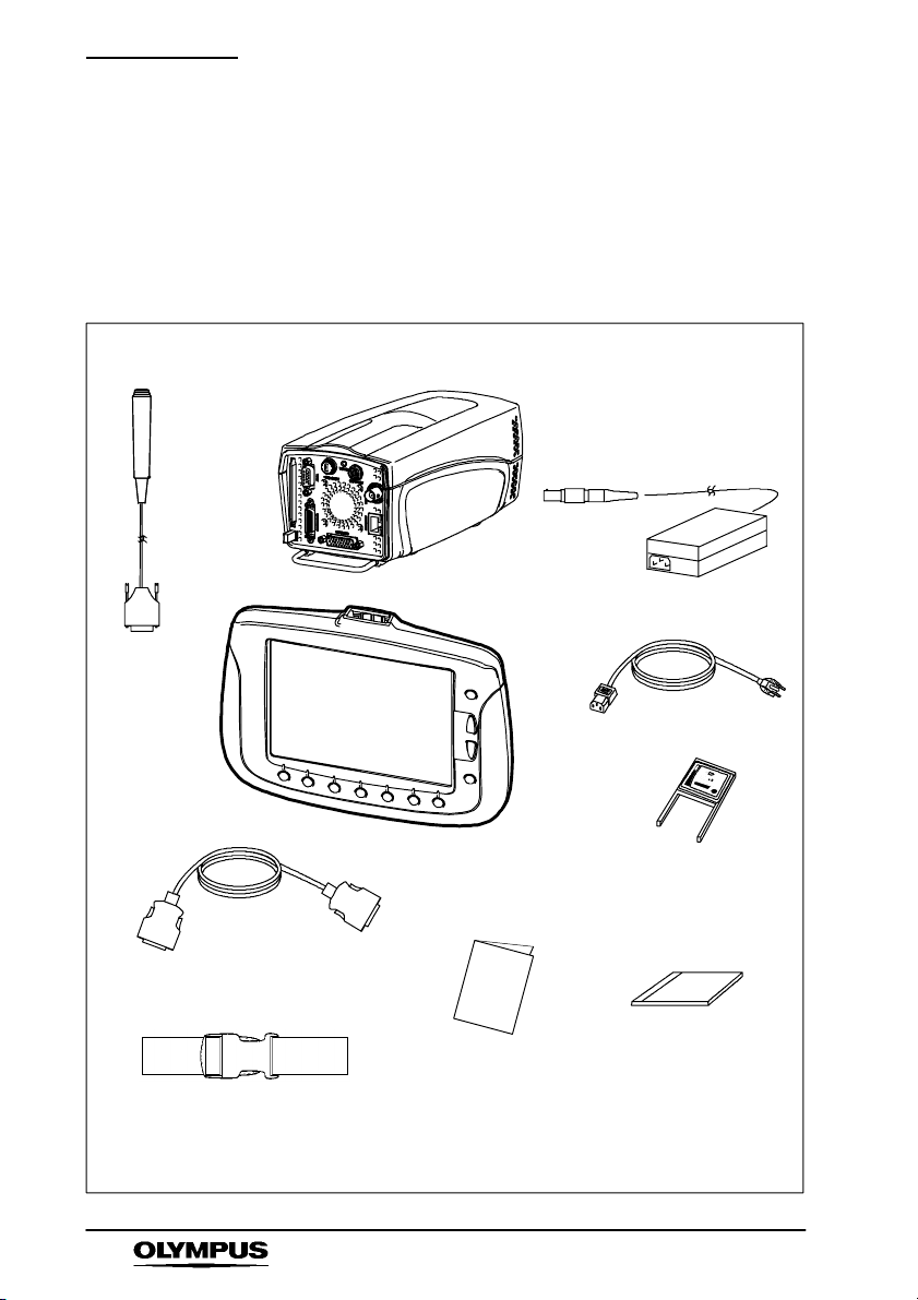
Checking the contents
Chapter 2 Checking the Package
Contents
Remove the transit sleeve and open the i--SPEED system case.
Match all items in the case with the items shown below. If any item
is missing or damaged contact Olympus.
Camera
Trigger
Switch
CDU
CDU cable 3m
Instructions for Use
Case strap
Note: The standard set does not include a compact flash card
i--SPEED viewer
software CD-- ROM
Power Supply
Mains Cable x3
Compact Flash
Adaptor
8 i--SPEED
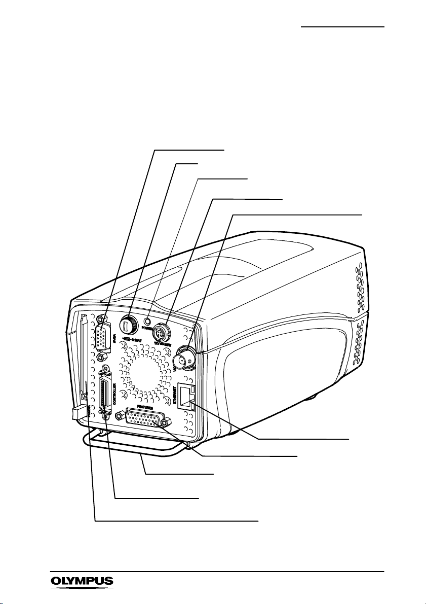
Nomenclature & Functions
Chapter 3 Nomenclature and
Functions
3.1 Camera
SVGA connector
Fuse
Power LED
Power connector
Composite video BNC connector
Ethernet connector
Feature connector
Protective bar
Controller connector
PCMCIA slot for compact flash adaptor
i--SPEED 9

Nomenclature & Functions
1. Power Connector
The rear panel Power connector is used to take power into the
camera, nominally 12V DC. This power is used to operate the
camera, but is also used to operate the CDU. The power input
is protected against reverse polarity connection and this will
normally result in a blown fuse.
2. Power LED
The power LED will illuminate when 12V is applied and the fuse
is operating correctly.
3. Fuse
The fuse is replaceable by the user and is accessed by
unscrewing the fuse holder. Care must be taken to replace the
fuse with one of the correct size, type and rating.
4. Composite Video BNC Connector
This connector provides an industry standard PAL or NTSC
composite colour video to a video monitor unit. BNC is an
industry standard connection for this type of signal. The video
available from the connector may be switched between NTSC
and PAL via the menu system in the CDU.
Composite video signals are designed to be driven into a
terminated connector, so care must be taken to ensure that the
last piece of equipment in the BNC cable chain is set to
terminatewith75Ohms.
5. Controller Connector
This connector is used to connect the CDU to the camera. It
carries power from the camera to the CDU, video from the
camera to the CDU and receives button press information from
the CDU.
Although this connector conforms to the LVDS industry
standard, it is recommended that only cables supplied by
Olympus are used and it is imperative that no equipment other
than the CDU is attached to this connector.
10 i--SPEED

Nomenclature & Functions
6. Ethernet Connector
Used for software updates if newer software becomes available.
7. SVGA Connector
This connector provides a SVGA signal which contains the
video image and overlay graphics. This signal is a copy of the
CDU image. The output standard is the 60Hz SVGA PC video
signal and the connector conforms to the PC video 15 pin D-- sub
standard. As a result, this signal may be fed directly to a PC
monitor, (CRT or LCD) and provides the best quality live
analogue video signal available from the camera.
8. PCMCIA Slot
The camera is able to operate a PCMCIA flash memory. The
standard used is the ATA FLASH standard and the card may be
either 3V3 or 5V. It is also possible to use a Compact Flash card
with the supplied PCMCIA adapter and this is recommended if
larger memory sizes are required. Once the card is inserted it
must be pressed firmly in place and may be ejected by pressing
the button at the bottom of the slot. It is not necessary to switch
power on and off as the card is inserted and removed, but care
must be taken not to remove the card while writing, deleting or
formatting is in progress.
i--SPEED 11

Nomenclature & Functions
9. Feature Connector
Trigger Input / Trigger Switch: This connector (and the
supplied trigger switch if required) are used to trigger the camera
while recording is in progress. Further details are provided in
Chapter 7 “Un
When the trigger is set to 0%, the trigger counter is set to the
length of the memory, so that the trigger point appears at the
beginning (0%) of the final video clip. A setting of 100% will
cause the recording to stop immediately, placing the trigger
event at the end of the video clip.
The signal is TTL level and the user may select rising edge or
falling edge trigger options.
The trigger input contains a “pull--up” resistor to enable the
supplied trigger switch to be used without further electronics. It
should be noted that the trigger switch provides a falling edge.
In practice, the trigger switch also produces a rising edge
because of switch bounce, but this cannot be guaranteed.
10. Cooling Holes
The rear panel has a number of cooling holes, and more are
located on the sides of the casework at the front of the unit. The
outer holes on the rear panel and the holes at the front of the
unit are air inlets and the holes in a circular pattern on the rear
are air outlets. The primary reason for including forced air
cooling has been to eliminate localised hot spots within the
electronics and care should be taken to ensure that the cooling
holes are kept clear at all times as described in Chapter
“Maintenance”
derstanding the Olympus i--SPEED”.
8
.
12 i--SPEED
Nomenclature & Functions
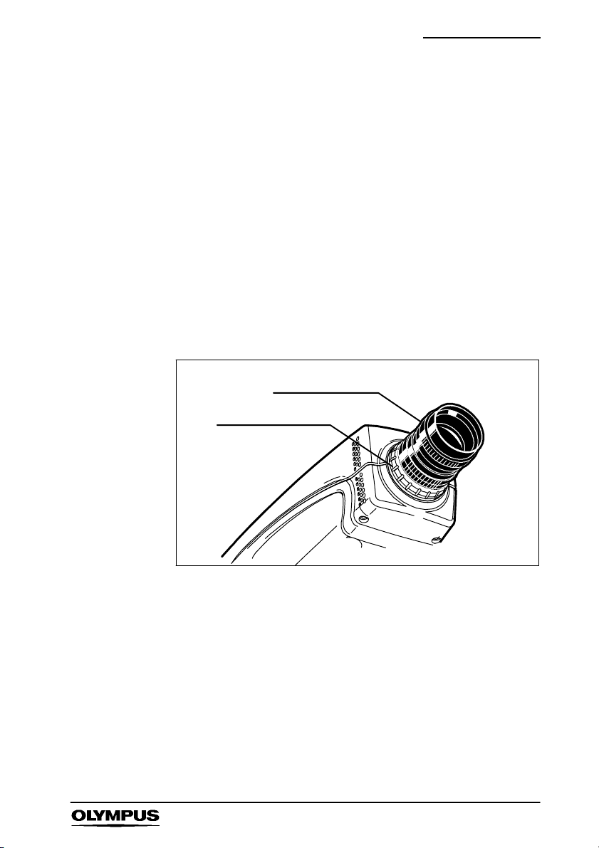
11. Back Focus Control
It is sometimes necessary to adjust the distance between the
C--mount face and the image sensor to accommodate lenses
from different manufacturers and lenses with different optical
tolerances. The Olympus
i--SPEED has a back focus
assembly located in the front of the unit to permit this
adjustment.
To adjust the back focus, screw a C--mount lens into the
C--mount in the normal way. Turn the locking ring anticlockwise
(when viewed from the front) to unlock the C--mount thread ring
then rotate the lens to adjust the back focus as required -- a
series of ‘click’ positions will be felt. When complete, the
adjustment should be left in one of these ‘click’ positions and the
locking ring rotated clockwise to lock the C--mount thread ring in
position.
C-- mount lens
Locking ring
As a guide, the correct setting of back focus is obtained by
pointing the camera at an object at a known distance from the
lens, preferably an “infinite” distance. The scale on the lens is
then used to set the focus ring to this distance. The back focus
is then adjusted to obtain the best image.
12. Mounting Holes
The base of the unit is fitted with 5 standard mounting holes. It
is recommended that the central hole is used for mounting the
camera (e.g. to a tripod) and the other holes may then be used
to mount light-- weight accessories to the camera.
i--SPEED 13
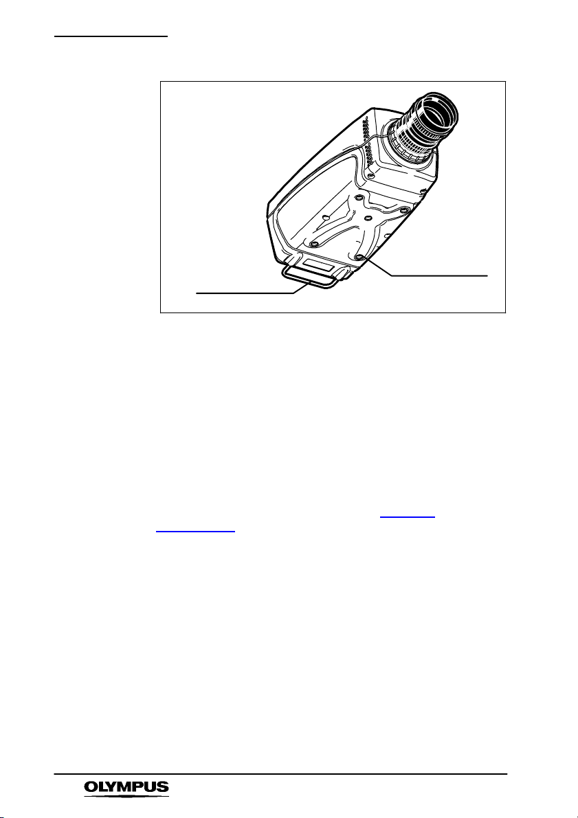
Nomenclature & Functions
13. Protective Bar
The back of the unit is fitted with a protective bar. The purpose
of this is to protect the connectors from damage if the unit is
placed on a s helf and pushed back against a wall. In spite of
this, the bar may also be used as a handle to carry the camera
or to support light-- weight items when the camera is mounted on
a tripod.
Mounting holes
Protective bar
14. Protective Glass
The image sensor is located at the front of the camera inside the
C--mount aperture. A protective glass is fitted to this aperture to
shield the sensor from dust and damage. It is recommended
that the glass is kept clean as detailed in Chapter
“Maintenance”
15. Battery Memory
The Olympus
memory. This is used to keep track of the time and date while
the camera is switched off. The memory is also used to store
some of the user controls, such as the TV monitor standard and
the language setting. The battery is a non--replaceable lithium
cell which should last for approximately 10 years. In the event of
battery failure, default values will be used at each switch--on.
14 i--SPEED
8
.
i--SPEED contains a battery powered clock and
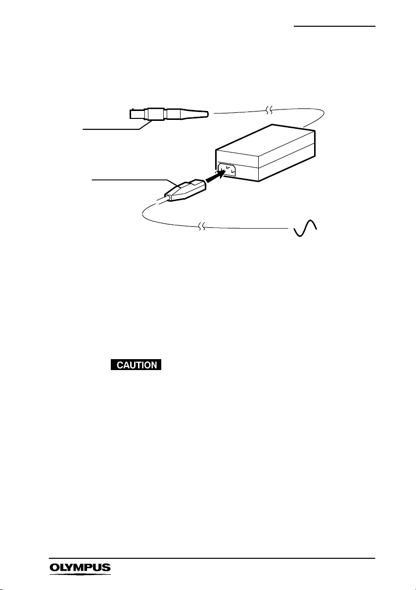
3.2 Power Supply/Mains cable
Power connector
Mains power cable
1. Power cable
The 12VDC Power supply is supplied with the appropriate AC
mains power cable. The power supply unit MUST be earthed
and it is recommended that the mains power cable s upplied is
used to maintain standards compliance.
Nomenclature & Functions
2. Power connector
Connects to the ‘power’ socket of the camera and provides
power to the camera and its controller unit.
The user must ensure that only the power supply
unit supplied with the Olympus i--SPEED is used
and that this unit is only used to power the
camera.
The memory in the camera will be erased if
power is lost.
i--SPEED 15

Nomenclature & Functions
3.3 Controller Display Unit (CDU)
Controller cable connector
CDU
Soft keys
Function keys
16 i--SPEED
Strap
Tripod mount
Stand
The CDU is not High--G rated. The CDU can be
detached and reattached without switching the
camera off.

Nomenclature & Functions
1. CDU
The CDU displays the image from the camera in real--time and
permits the most flexible use of the camera, by using a series of
buttons around the outside of the screen. The CDU is connected
to the camera’s Controller connector via a 3m controller cable (a
10m cable is available as an optional accessory). The CDU
takes power and video from the camera and requires no
batteries or further connections.
LCD Panel, Viewing Angle: At the time of design and writing
this manual, the LCD panel used in the CDU is the best
available LCD panel of this size and resolution. Even this
market leading panel, however, has a restricted viewing angle in
the vertical direction and the user is advised to experiment with
the CDU to find the optimum angle at which to view the image.
Protective Screen: Although the CDU LCD screen is protected
by a tough plastic sheet, it is still recommended that care is
exercised when handling this unit. It is also important to keep
this screen clean to preserve its anti--glare properties and this is
detailed in Chapter 8 “Maintenance”
.
2. Soft keys
The bottom seven buttons on the CDU are used as “soft keys”,
that is the function of each button is dependant on the text
written above to it on the screen.
3. Function keys
The four buttons on the right hand side of the CDU are
dedicated function buttons, these are Text, Back, Up and Down.
The menu system has been specially constructed to take
maximum advantage of this layout.
4. Stand
The CDU is equipped with a stand which may be set to a
number of ‘click-- stop’ positions to allow standing on a flat
surface at various angles or hanging from a convenient hook.
The stand may also be folded flat for storage or when the strap
is used.
i--SPEED 17

Nomenclature & Functions
5. Strap
The back of CDU has an adjustable strap which may be used to
allow the unit to be conveniently held with a single hand.
6. Tripod Mount
The CDU contains a tripod mounting hole with the industry
standard thread and is located under the strap.
The CDU must not be connected to any
equipment other than the Olympus
camera, otherwise equipment damage will occur.
To maintain standards compliance, it is
recommended that only cables supplied by
Olympus are used.
i--SPEED
18 i--SPEED

System Connection
Chapter 4 System Connection
Refer to the diagram shown below and connect the system.
Optional
PC/TV monitor
3
8*
9*
1
2
4
3
1
Key
1 Trigger switch 6 Mains power cable
2 CDU (Controller Display Unit) 7 C--Mount lens*
3 Controller cable 8 VGA cable *
4 Camera 9 Composite video BNC cable*
5 Power supply unit (PSU)
*not supplied in the standard set
7*
5
6
i--SPEED 19

Getting Started
Chapter 5 Getting Started
This section provides a functional description followed by the basic steps
required to start using the
5.1 Functional Description
Assuming the system has been connected as described in Chapter 4,the
typical sequence of events is as follows:
After the sensor has been calibrated, the frame speed and shutter settings
are chosen, the lighting and lens are adjusted appropriately and the
camera is placed in record mode.
The camera then takes video at high frame rates and stores it in the
built--in memory. This memory is configured in a circle so that, once the
memory is full, each new frame replaces the oldest stored frame. In this
way, the camera keeps a rolling history of the scene it views and this
process can continue indefinitely. Once the desired event has occurred,
the camera is stopped or triggered.
During the entire set--up and record process, the CDU and any monitor
attached will display the live image in full colour and in real time.
i--SPEED camera system.
Once the required video clip is stored in memory, it may be viewed by
using the player function. In this mode, video may be played forwards or
backwards at a range of speeds. A convenient bookmark system is
provided for easy navigation between sections of interest.
The memory in the camera will be erased without power, so if it is
necessary to preserve the captured video after power off, it may recorded
onto a PCMCIA memory card, which is inserted into the card slot provided.
The internal memory is much bigger than any card currently available, so
only a subsection of video may be stored. High speed video clips
generally contain a large amount of “dead time” and a relatively small
amount of useful motion, in recognition of this, the Olympus i--SPEED has
a clip select function which allows a precise choice of the video to be
saved.
20 i--SPEED

Getting Started
5.2 Controlling the camera with the CDU
This section describes the basic steps required to start using the
i--SPEED camera system with the CDU. Additional information regarding
functionality of the CDU can be found in Chapter 6
1. Connect the system as described in Chapter 4, then connect the
mains power cable to a s uitable AC wall outlet and switch the
power ON -- the i--SPEED splash screen is displayed on the CDU.
.
2. Press any key, a live video image is displayed on the CDU.
i--SPEED 21

Getting Started
3. Once the camera has been switched on, the image will contain
fixed noise. This must be removed by pressing “Config” then
“Calibrate sensor”. Immediately the “Calibrate sensor” button is
pressed, the lens must be completely covered to provide total
darkness to the sensor for the duration of the process. An
on-- screen message will show the progress of the calibration
process. Press “Back” to return to the i--SPEED Home screen.
4. Adjust the lens focus and iris as required to achieve a sharp, bright
image.
5. Depress the Speed and Shutter buttons to select the desired frame
speed (def: 60fps) and shutter speed (def: x1). You may need to
re--adjust the lens focus and iris to achieve a sharp, bright image.
6. Depress the Record button, a camera icon is displayed and the
camera records video into its circular buffer until the Stop button is
depressed or the trigger button is pressed.
If the trigger is used, recording will stop after a delay.
This delay depends on the trigger position setting and
frame speed.
22 i--SPEED

Getting Started
When recording has stopped, whether by trigger or STOP button,
the camera will present the Player menu and display the first
recorded image in the memory.
7. Player controls are: jump back, play backwards, play forwards,
jump forward (to bookmark). Each button when pressed changes to
a Stop button.
The Bookmark control is used to set bookmarks at points of interest
and are displayed as white vertical lines in the progress bar at the
top of the screen. When the Trigger is used, an automatic
bookmark is displayed as a Red vertical line.
i--SPEED 23

Getting Started
8. Use the up/down buttons on the right hand side of the CDU to
adjust playback speed.
9. If the video clip is to be saved, insert a PCMCIA memory card into
PCMCIA slot in the camera.
10. Use the player controls to navigate to the desired start position.
Press Clip select and press Clip start. Press Back to return to the
player, navigate to the desired end position. Press Clip select and
select Clip end.
Frame and memory status is displayed top right.
Note that Clip select will not be available until a card is
inserted.
11. Depress Save.
12. Depress BACK as required to return to the Home menu.
24 i--SPEED

Software reference CDU
Chapter 6 Embedded Software
Reference (CDU)
Introduction
This reference section describes the camera’s embedded software
and its user interface from the viewpoint of the CDU. In this
section, items which are printed like this
menu, controls are described whenever they appear in a menu.
Operation of the CDU menus
To navigate through the menu system, the button nearest the
desired selection is pressed.
When a control is selected, the desired value may be chosen by
using the
Repeatedly pressing or to press and hold the control button will
cycle through the available values. The current value is displayed
above the control button and also next to the
To return to a higher menu, the Back button is pressed. If there is a
requirement for a text free screen, the Text button is used to cycle
the on-- screen text through full, time/date only and off options.
Y and B buttons on the right hand side of the screen.
signify the name of a sub
YBbuttons.
i--SPEED 25

Software reference CDU
6.1 Menu Screens
1. OLYMPUS i--SPEED Splash Screen
This screen is displayed while the camera starts up and configures
the internal software. It contains data on the memory configuration
of the camera, the serial number and the software version number.
To exit this screen, the user must press a button on the CDU.
26 i--SPEED

Software reference CDU
2. i--SPEED Home Me n u
This is the top level or home screen of the menu system. It may be
accessed by pressing the Back button repeatedly from any position
in the menu system.
Access: i-- SPEED Home
Options: Record
S The CDU will display the live image
Speed Shutter Playback Card Config WB Set
` Speed Control
This control allows the user to set the frame speed of the camera.
The lowest speed available is 60 frames per second as this is
almost equal to the SVGA display specification. The maximum
speed is fixed to 1,000fps.
As described in Chapter 7 “Un
the user will normally need to open the iris of the lens and/or add
more light as the speed is increased.
derstanding the Olympus i--SPEED”,
i--SPEED 27

Software reference CDU
` Shutter Control
It is sometimes desirable to reduce the time during which the
sensor gathers light (called “exposure time”, “integration time” or
“shutter time”) in order to reduce motion blur and “freeze” the
motion in each frame. The default shutter time is equal to the frame
time, but this may be reduced by this control. The shutter time is
measured as the ratio between frame time and shutter time, e.g.
x10 means that the shutter is open for 1/10 of the frame period. The
shutter period may range from the frame period (x1) to 1/200 of the
frame period (x200).
The user should note that as the shutter ratio is increased, the
camera will require more light.
` WB Set Control
This control activates the automatic white balance function. Before
pressing this control, the user must place a pure white reference
(sheet of paper etc.) in front of the camera, completely filling the
field of view. This must not be removed until the white balance is
complete. An on screen message shows the status of the white
balance process.
Please refer to Chapter 7 “Understanding the Olympus
for a further description.
Once this is set, the white balance setting is stored in
the camera’s internal memory.
28 i--SPEED
i--SPEED”

Software reference CDU
3. Recording Menu
When this menu is displayed, the Olympus i-- SPEED is recording
video into its circular buffer. The record action is confirmed by the
presence of a small animated camera icon. When a trigger signal
is received and the camera is working through the length of its
trigger counter, the animation is supplemented by a ‘stop watch
icon.
When recording has stopped, whether by the trigger or the STOP
control, the camera will automatically present the Playback Menu
and thereby display the first recorded image in the memory.
’
Access: i-- SPEED Home
Options:STOP
S The CDU will display the live image
' Record
` STOP Control
This control will cause the camera to stop recording immediately,
regardless of the setting of the trigger position.
i--SPEED 29

Software reference CDU
4. Player Menu
This specialised screen allows the user to play back and interact
with the video stored in the circular buffer memory.
Access: i-- SPEED Home
Options: Jump back Reverse play Forward play Jump forward
Clip select
S The CDU will display the playback images required by the
player controls
' Playback
Bookmark
` Player Controls
The controls should be familiar to most users: jump back, play
backwards, play forwards, jump forward.
The jump controls will cause the player to immediately move either
to the next bookmark or to the beginning/end of the memory.
The speed of playback is controlled by the
hand side of the CDU. The chosen playback speed is indicated in
a label next to these buttons. This may be used to “Fast forward” or
“Rewind” the video.
YBbuttons on the right
` Bookmark Control
This control is used to set bookmarks at points of interest.
Pressing the button when already on a marked frame will remove
the bookmark. Bookmarks are displayed in the progress bar at the
top of the screen. For the convenience of the user, the trigger
frame is automatically given its own bookmark, and this is coloured
differently for clarity.
30 i--SPEED

Software reference CDU
` On Screen Information
The player provides a progress bar at the top of the screen to
indicate the relative position within the circular buffer of the
currently displayed frame. This bar is also used to display
bookmarks. In the same display panel as the progress bar is a
numerical description of the frame number, the total number of
frames in memory and the time of the current frame relative to the
startofthememory.
i--SPEED 31

Software reference CDU
5. Card Management Menu
This menu makes available the items which relate to the
management of the PCMCIA removable memory card, both ATA
and Compact FLASH.
The screen includes a list of the files on the card and one of these
will be highlighted by a selection bar.
Automatically appears after s aving a file
Access: i-- SPEED Home
i--SPEED Home
Options: Delete Format
The CDU will display the card directory.
' Card
' Player ' Clip select ' Card
` Delete Control
This control is used to delete the selected file from the card. The
user is protected from error by a confirmation question.
` Format Control
The user is able to format the card. This will delete all the data on
the card and also prepare a new card for its first use. The user is
protected from error by a confirmation question.
32 i--SPEED

Software reference CDU
6. Config Menu
This menu makes available all the items which relate to the
configuration of the camera.
Access: i-- SPEED Home
Options: Time/Date Language TV Monitor Calibrate
Sensor Trigger edge Trigger pos
' Config Menu
` Language Control
This control permits the user to set the language in which the
menus are displayed. The language of the information tiles and
control value display is not changed.
` TV Monitor Control
The composite video output connector (BNC) is able to provide
either NTSC or PAL and this selection is made by this control.
i--SPEED 33

Software reference CDU
` Calibrate Sensor Control
In common with all CMOS sensor chips, the Olympus i-- SPEED
sensor requires a calibration system to remove fixed pattern noise.
The Olympus i --SPEED provides an off--chip calibration system. To
calibrate the sensor, the user must press the “Calibrate” button and
then completely cover the lens to exclude all light. An on --screen
message allows the user a brief time to do this. The calibration then
occurs and the message is removed once this is complete. Further
discussion may be found in Chapter 7 “Understanding the
i--SPEED
` Trigger Edge Control
This control sets the trigger detection system to wait for a rising
edge or a falling edge on the trigger input connection.
` Trigger Position Control
This control sets the length of the trigger delay, so that the trigger
point will appear at a user--settable position in the recorded video
clip. With the trigger position at 0%, the trigger delay is equal to the
length of the circular buffer and the trigger point will appear at the
beginning of the video clip. With the trigger position at 100%, the
trigger counter is set to zero and the recording will stop immediately
the trigger is activated, thus the trigger point will appear at the end
of the video clip. There are a number of options available in
between 0% and 100%.
Olympus
”.
34 i--SPEED

Software reference CDU
7. Clip Select Menu
This menu makes available all the items which relate to selecting
the video clip to be saved on the PCMCIA card.
Access: i-- SPEED Home
Options: Clip start Clip end Card Save
S The CDU will display the playback images required
by the clip select controls
' Playback ' Clip select
` Player
The user may access the player by pressing the “Back” button.
` Clip Start and Clip End Controls
The player controls are used to locate the start and end of the
desired video clip and the Clip Start and Clip End controls are used
to mark the chosen frames.
` Save Control
If the start and end frames are selected as the same frame, the
save control will cause the camera to save a single bitmap (BMP)
image to the card. If more than one frame is chosen, the camera
will save a movie (AVI) file to the card.
i--SPEED 35

Software reference CDU
` On Screen Information
The Clip Select menu provides a progress bar to indicate the
position in the buffer memory of the currently displayed frame as
well as the start and end frame markers. This bar is also used to
display bookmarks.
In the same display panel as the progress bar is a graphical
representation of the available memory in the card, the total
memory in the card and the quantity of memory required for the
currently selected clip.
In a separate display panel is a numerical description of start frame
number relative to the start of the camera
frames selected, the size of the chosen clip and the available free
memory in the card.
8. Time / Date Setting Menu
This menu permits the setting of the time and date of the on--board
clock of the camera.
When the appropriate time and date have been set, the OK button
should be pressed.
’s memory, the number of
Access: i-- SPEED Home
Options: Year Month Day Hour Minute Second OK
S The CDU will display the splash screen logo
` OK Control
This control confirms the numerical entry just made and also
returns to the previous menu.
36 i--SPEED
' Config ' Time/Date

Understanding i-- SPEED
Chapter 7 Understanding the
Olympus i- SPEED
The Olympus i --SPEED has been designed with ease of use in mind and
all the functions of the camera are accessed via clear and descriptive
menus. Every effort has been made to ensure that the menus are intuitive.
High speed video, however is a complex subject in itself and several of the
functions of the Olympus i--SPEED are necessarily complex. Reading the
following section will provide the user with sufficient knowledge of these
areas to begin to understand the menus themselves. A detailed
description of the menus is given earlier.
` Speed
The camera contains electronic memory to hold the video images
as they are captured and this has a specific size. The memory is
therefore capable of holding a fixed number of full resolution
images and there is a clearly defined maximum recording time at
1,000fps.
If the frame rate is reduced below 1,000fps, the available record
time will increase because the images are arriving less frequently.
There is a further trade--off associated with frame speed and this is
discussed below.
` Shutter, Speed, Sensitivity
The sensor operates by capturing light, converting it to an
electronic facsimile of the optical image and supplying the memory
with the image while the cycle begins to repeat. The period during
which light is captured is called the “integration time”, “exposure
time” or “shutter time”. The shutter time is normally equal to the
maximum time available during the frame, called the “frame period”.
If the scene contains a very fast moving object, the object may
move an appreciable distance during the frame period and this will
cause the object to appear blurred. This “motion blur” is sometimes
undesirable, so the Olympus i--SPEED is able to reduce the
shutter time to a fraction of the frame period and this causes the
object to be “frozen” in each frame. The shutter time is usually
measured as the ratio between frame period and shutter time, e.g.
10x means that the shutter is open for 1/10 of the frame period.
Reducing the shutter time however, reduces the amount of time the
camera spends gathering light and the image will become dimmer.
For this reason, increasing the shutter setting will normally require
the addition of extra light to the scene.
i--SPEED 37

Understanding i-- SPEED
A similar effect is found when the frame speed is increased. The
available shutter time is reduced because the frame period is
reduced -- the faster the frames are taken, the less time is spent on
each one. As a result of this, increasing frame speed will normally
require the addition of extra light to the scene.
` Internal Memory, Circular buffer
When in record mode, the camera continuously stores frames in its
internal memory. That memory is configured in a circle so that,
once the memory is full, each new frame replaces the oldest stored
frame. In this way, the camera keeps a rolling history of the scene
it views and this process can continue indefinitely. This
configuration of the memory is called a “circular buffer”.
Once the desired event has occurred, the camera may be stopped
by pressing a menu button or raising a trigger event as discussed
below.
` Trigger
As mentioned above, the Olympus i-- SPEED records video in a
circular buffer and can do so indefinitely. At some point, however, it
is necessary to stop the recording process in order to preserve the
data in the memory.
The method of stopping the camera is highly important as it is this
which guarantees the capture of the event in question. There are
two methods of stopping the Olympus i --SPEED .Thefirstisa
button press in the menu system and this immediately stops the
record process, so that the memory contains the history prior to the
button press.
The second method is to use an external electrical trigger, which
causes the camera to stop after a user-- settable delay. By
permitting the camera to record for a brief time after the trigger,
some history before the trigger and also some future after the
trigger are preserved in the memory. In this way, the trigger may
occur in the middle of the event of interest and yet the camera can
still capture the whole event.
The delay between the trigger event and the cessation of recording
is controlled by a frame counter known as the trigger counter. The
length of this count is controlled by the menu system and is
expressed as a percentage of the total available record time of the
camera’s memory.
The counter value is described from the viewpoint of the final
recorded video clip, so that a setting of 0% sets the counter to
delay for the entire length of the circular buffer. In this way, the
38 i--SPEED

Understanding i-- SPEED
trigger event will appear at the beginning of the video clip.
Similarly, a setting of 100% will cause the camera to stop
immediately a trigger is received, and this will place the trigger
event at the end of the recorded video clip.
Since the trigger is an electrical signal, the Olympus i--SPEED ma y
be set to wait for either the rising or the falling edge of the trigger
pulse.
` Sensor, FPN, FPN Calibration
The image sensor used in the Olympus i--SPEED camera is a
CMOS chip and, like all CMOS imagers, it has the property of
introducing fixed pattern noise (FPN) onto the image. Most HSVC
manufacturers provide some form of correction to remove the FPN.
FPN will give the image a gritty appearance, almost as though the
picture has been printed onto sandpaper, and may also produce
thin vertical stripes.
To calibrate the sensor, the user must press the “Calibrate” button
and then completely cover the lens to exclude all light. An
on-- screen message allows the user a brief time to do this. The
calibration then occurs and the message is removed once this is
complete.
The control to manually trigger the calibration is found in the config
menu.
` White Balance
The human eye automatically adjusts its colour processing in order
to make white objects look “white” in spite of varying ambient
lighting colour. When viewing video on a monitor, however, the eye
judges white based on the ambient around the monitor, not on the
ambient around the camera. For this reason, a colour camera must
also adjust its processing to compensate for the ambient lighting
and configure its output to produce the electronic version of pure
white (red = green = blue) when a white object is viewed. In this
way, the camera can render white objects as white on the monitor,
in spite of ambient light coloration. This function is called white
balance.
i--SPEED 39

Understanding i-- SPEED
The Olympus i --SPEED provides an automatic white balance
which relies on the user placing a pure white reference (sheet of
paper etc.) in front of the camera, completely filling the field of view
and then pressing the WB Set button. When this is done, the
camera will sample the reference and reconfigure its processing
electronics to render this as pure white. The reference must not be
removed until the white balance is complete, so an on screen
message shows the status of the white balance process.
` Lighting
The Olympus i --SPEED has been designed to remove most of the
difficulty associated with taking high speed video shots, but two
areas of critical importance still remain, lenses and lighting. In
many cases, most of the time taken when working with the
Olympus i--SPEED will be used in setting up the lighting, framing
the shot and choosing the correct lens.
Earlier sections of this document have described how the shutter
time and speed setting of the camera dramatically increase the
requirement for light. The result of this is that most high speed
video applications require a large amount of lighting and this is a
common theme in the high speed video industry. As a rough guide,
most indoor shots require 500 to 2,000 watts of additional lighting.
This is traditionally provided by shining a few high power spot lights
on the target scene but, for smaller targets, the Olympus range of
industrial light sources and light guides provide ideal illumination.
Simply providing a large wattage of light is not suitable for most
applications. It is usually necessary to carefully focus and target
the light, so general purpose floodlights are not normally useful in
HSV work.
An illustration is given from the experience of the i--SPEED
development team. A car parts manufacturer wished to view a
rapid movement in the mechanism of a prototype seatbelt reel.
The scene was illuminated with several 1,000 watt garden
floodlights, but this was sufficient for only a few hundred frames per
second. The lighting was removed and replaced by a single
specialised 500 watt spotlight and this permitted operation at 1,000
fps. When faster operation was required, the spotlight was
augmented by an Olympus Industrial light source and liquid light
guide and this increased the operating speed to 4,000fps.
This example is included to show that the quantity of light is
significantly less important than the concentration of light. Olympus
representatives are able to supply specialised lighting which has
been selected to be suitable for most high speed video
applications.
40 i--SPEED

Understanding i-- SPEED
` View Finder
In contrast with some other manufacturer’s products, the Olympus
i--SPEED camera presents the live image on the CDU or monitor
screen at all possible times. Some menus do require the image to
be obscured and the splash screen logo is used for this purpose.
Also, the playback screen is used to display the contents of the
memory buffer, rather than a live image. During the live view and
the record process, however, the screen will display a live, colour,
real time image, updated at 60 frames per second.
` Lenses
The choice of lens can make a dramatic difference to the video
images obtained.
Choosing the lens must begin with the focal length, which is
expressed in mm. A lens with a large focal length would normally
be chosen when a small area is to be viewed or the camera is to be
a long distance away from the scene, because a longer focal length
means a greater magnification. This type of lens has the
disadvantage of reducing the apparent distance between objects
which are arranged axially with the camera. This is called
foreshortening. Lenses with long focal lengths also tend to have a
smaller maximum iris setting (higher f number) and are dimmer
than short focal length lenses.
A lens with a short focal length is chosen when a wide area is to be
viewed, or the camera is to be placed near to the scene. Lenses
with a very short focal length have the disadvantage of distorting
the perspective of the image and this is called barrel distortion.
Normal lenses have a controllable iris or aperture. The iris controls
the amount of light available to the camera. The higher the f
number, the less light the lens transmits. Increasing the number by
1.4 times (e.g. from f/4 to f/5.6), is called 1 stop and halves the light
throughput.
There is a secondary effect of reducing the iris (increasing the f
number) and this is an increase in the depth of field. This means
that the lens is more able to focus on close and distant objects
simultaneously, so a small iris setting is advantageous.
This is in conflict with the normal HSV requirement for as much light
as possible, especially at high speeds and fast shutter times.
Probably the greatest art in lens set--up is striking a balance
between getting all objects in the scene into focus and having a
bright enough image. It is advisable in general to operate with a
smaller iris (higher f number) and add more light.
i--SPEED 41

Understanding i-- SPEED
It is not possible to specify an ideal lens, because photography is
dependant on the object being photographed, but an “average”
lens for the Olympus i--SPEED would have a focal length of 25mm
and an iris range of f/1.4 to f/22.
When purchasing lenses for the Olympus i--SPEED ,itmustbe
remembered that the CMOS imager is quite large in size, so a 1”
format (minimum) lens is required.
42 i--SPEED

Chapter 8 Maintenance
8.1 Cleaning
To prevent electric shock or damage to equipment, always disconnect
from the power supply before attempting to clean.
Maintenance
Camera CMOS protective glass and CDU
Clean using lens tissues moistened with a solvent solution
composed of 70% ether / 30% industrial methylated spirits.
DO NOT use hard or abrasive materials.
Camera cooling holes
Periodically inspect the camera cooling holes to ensure they are
not blocked with fluff, dirt etc. Clean as necessary.
General cleaning
Wipe equipment clean with a soft cloth dampened with a mild
detergent solution.
8.2 Storage and transportation
After use
Always pack the product in the kit case after use or for
transportation.
Case strap
For security and to prevent inadvertent opening of the case during
transportation, it is recommended that the case strap is secured
around the case.
screen
8.3 Repair
The i--SPEED camera contains a user replaceable fuse located in
the rear panel
i--SPEED 43
. There are no other user repairable components.

Spares & Accessories
Chapter 9 Spares and Accessories
Spares
Camera-- Colour .......................................... K10004130
Camera-- Mono ........................................... K10004129
ControllerDisplayUnit...................................... K7504248
Power Supply ............................................. K7505046
MainsCable -- UK ......................................... 7145454
MainsCable -- Europe...................................... 7145462
MainsCable -- USA ........................................ 7318375
Instructions(English) ....................................... K10004139
Camerafuse(packof5) .................................... 7502254
ControllerCable,3m ....................................... K7504982
Trigger Switch ............................................. K10004138
PCMCIA Compact Flash Adapter ............................ K7505053
TransitCasewithOuterSleeve .............................. K7505054
Casestrap................................................ K3931429
Part No.
Accessories
ControllerCable,10m ...................................... K7504984
12V DC input cable ........................................ K7504985
CompactFlashCard--1Gb ................................. 1163123
In addition to the above items, a range of flash cards, tripods, lenses and lighting
equipment is also available, along with three PC software options, Basic,
Advanced and Deluxe. Please contact Olympus for further information.
44 i--SPEED

Chapter 10 Specifications
10.1 i- SPEED Camera
` Camera physical
Dimensions
Size W 106mm x H 98mm x L 264mm nominal
Weight 2kg nominal
Mechanical connections
Tripod mounting
Lens mounting Standard C-- mount
Back focus Nominal position 17mm. C--mount can be screwed
Accessory mounting
` Electrical connections
1x standard tripod mount (¼” Whitworth thread)
in 1mm & out 3mm.
Rotary control locks the C-- mount in position
4x ¼” Whitworth thread fixing holes on the base
Specifications
Power input Lemo EGG.OB.304.CLV
Pinout 1 Ground 3 +12V
2 +12V 4 Ground
Input voltage
Power consumption Camera: 28W max
Fuse
Type 20 x 5mm cartridge (coin slot screw access)
Rating 3.15AH 250V
Controller Connector
Standard LVDS connector, 26 way MDR
Feature connector 26 way high density D sub female
Pinout 3 Trigger input 4 Trigger ground
Trigger in Level: 5V TTL, 12V maximum
12VDC ±10%
System: 36W max
Impedance: 10k ohms (pulled to +5V for trigger switch)
i--SPEED 45

Specifications
Ethernet RJ45: Used for software update if further releases
become available
Pinout 1 TXD1+ 5 NC
2 TXD1-- 6 RXD2--
3 RXD2+ 7 NC
4 NC 8 NC
Ethernet signal 10 / 100 Base--T, auto s witching
Link (in RJ45) Link status is indicated by two bi--colour red--green
LED’s:
Top red: 100Mb connection, half--duplex link
Top green: 100Mb connection, full --duplex link
Bottom red: 10Mb connection, half--duplex link
Bottom green: 10Mb connection, full--duplex link
Activity (in RJ45) Indicated by flashing of the appropriate LED in the
appropriate colour (see above)
SVGA 15 way high density D sub female, PC standard
Pinout 1 Red video 6 Red ground
2 Green video 7 Green ground
3 Blue video 8 Blue ground
13 Horizontal sync 10 Sync ground
14 Vertical sync * Other pins no
connection
SVGA video output SVGA (800 x 600) 60Hz
Composite
video out
Standard NTSC / PAL switchable
Level 1Vp--p
Impedance 75 Ohms
PCMCIA Port
Standard PCMCIA “memory card” format
Vpp Level 0V, 5V, auto select
Vcc Level 3V3, 5V, auto select
Connection Hot swappable
BNC
ATA specification, Type II
46 i--SPEED

` Performance characteristics
Resolutions, speeds & record times
Sensor CMOS
Resolution 800 x 600 active pixels
Frame rate Maximum: 1,000 fps
Minimum: 60 fps
Nominal values of speeds and resolutions
Resolution
HV
800 600 480000 60 2236 37.27
800 600 480000 100 2236 22.36
800 600 480000 150 2236 14.91
800 600 480000 200 2236 11.18
800 600 480000 300 2236 7.45
800 600 480000 400 2236 5.59
800 600 480000 500 2236 4.47
800 600 480000 600 2236 3.73
800 600 480000 800 2236 2.80
800 600 480000 1000 2236 2.24
Trigger
Trigger input Position:
Pixels
per frame
User controllable, variable in 10% steps as follows:
Frame
speed
Images in
Memory
Specifications
Record
time
0% (recording stops one full buffer length after the
trigger, so video clip starts at trigger moment)
100% (recording stops immediately, preserving previous
video so video clip ends at trigger moment)Edge:
Programmable in menu system
Shutter
Normal mode Range: Frame time to frame time / 200 (200x)
i--SPEED 47

Specifications
Video update for Controller Display Unit & SVGA port
Refresh rate The LCD will be refreshed at 60Hz, regardless of video
or graphics activity
Playback rate Video may be played back at speeds from stop frame
up to 3,840Hz
Viewfinder mode At all times, except during playback, video from the
sensor will be displayed on the screen at an update rate
of 60Hz.
Fixed pattern noise correction
Resolution Full resolution of CMOS sensor
Effectiveness Correction to 0.4%
Black reference Manual, by user
White balance
Type Auto white balance, single shot operation, no time limit
on hold, and pre--set options
Range To correct for daylight, fluorescent light, 60W mains
tungsten (Anglepoise) and the full range of Olympus
light sources.
PCMCIA card interface
File type The video will be saved in “*.AVI” and “*.BMP” format,
non--compressed and with no audio channel,
compatible with Windows 95/98/ME/NT/2000/XP
Filing system FAT 32 style system, c ompatible with windows
95/98/ME/NT/2000/XP
Data The user data and other information will also be saved
to the PCMCIA card, locked to the relevant image
Card functions Format, delete file, select clip start and end
Real time clock & settings memory
Purpose The system will retain the time of day and date while the
power is switched off, along with key user settings
Retention time The battery will power the clock for approx. 10 years
Battery type Lithium coin cell
` Software facilities
General
Languages English, French, German, Spanish
48 i--SPEED

10.2 Controller Display Unit (CDU)
Dimensions
Size W 273mm x H 214mm x D 51mm nominal
Weight 1.5kg nominal
Stand
Connector
Type Standard LVDS connector, 26 way MDR
Electrical
Input voltage
Input power <2W, <8W at nominal voltages, derived from
Resolution 800 x 600
Brightness 350 cd/m
A flip--out stand with ratchet positions of: --3_,42_,
87_, 132_, 177_. When in the 177_ position, the
stand can be used as a hanger
5V ± 10%, 12V ± 10%
camera
2
10.3 Cables
Specifications
Controller cable (2 sizes)
Length 3m (& 10m accessory)
Cable type Multicore, double screened
Connectors Overmoulded LVDS, 26 way MDR
12V DC cable accessory
Length 2.2m
Cable type 6 core, round
Connectors Lemo FGG.OB.304.CLAD52Z
User equipment
connector
Pinout 1 +12V 2 Ground
XLR--3M
3 N/C Body Braid screen
i--SPEED 49

Specifications
10.4 Power supply
Dimensions
Size 130mm x 58mm x 30mm nominal
Weight 0.4kg nominal
Mains input
Socket type IEC
Fuse Internal, not user replaceable
Power output
Lead length 2.2m nominal
Connector Lemo FGG.OB.304.CLAD52Z
Electrical
Input
Output 12VDC, 36W minimum
10.5 Trigger switch
Dimensions
Size L 90mm x 20mm diameter nominal
Weight 60g nominal
Cable Integral, black, 2m nominal length, with strain relief
Connector 26 pin D--type high density male
Switch Press to c lose, momentary
100–240VAC ± 10%, 50--60Hz
i--SPEED 2
For higher frame rate, larger internal memory and cameras with data logging
capability, please see our range of i--SPEED 2 cameras.
50 i--SPEED

10.6 Regulatory Status
This mark on the i --SPEED camera indicates conformity with
the requirements of EC Directives 89/336/EEC relating to
electromagnetic compatibility and for the 12V DC power
supply, compliance with Directive 73/23/EEC, as amended
by 93/68/EEC, relating to electrical equipment designed for
use within certain limits (Low Voltage Directive). The
i--SPEED camera has been designed and tested to meet the
requirements of the following standards:
EN 61000--6--4:2001 EMC Emissions
EN 61000--6--2:2001 EMC Immunity
EN 61000--3--2/3:2000
EN 60950 Electrical Safety
10.7 Environmental
Specifications
Temperature
Pressure 71kPa to 106kPa
Relative humidity
Fluid ingress All items: No resistance to fluid ingress
Attitude of operation All items will be capable of operation in any
Attitude of storage /
transit
Operation: 0˚Cto+40˚C
Storage: --20˚Cto+60˚C
95% at 40˚C non--condensing
orientation
All items will be capable of storing / transporting in
any orientation
i--SPEED 51

Specifications
10.8 Compatibility
Interchangeability
Any item in the standard set or accessories may be changed for another
identical item and the system will still function correctly.
External compatibility
Light sources ALS--150U, KLS--3250, ILH--2 series, ILK--7 s eries,
Borescopes Series 5 Borescopes, IFxD4 Fiberscopes, IFxC5
Adaptors AK2--10C, AK2--5C, AK2-- 20C, AI--10C, AI--11C,
Lenses Standard range of C--mount lenses:
TV monitors PAL, NTSC and auto selecting video monitors,
PC monitors Standard PC SVGA compatible monitors
ILV--C1, ILK--C ILV--2, ILP--1 (note that the ILP--1
lamp operates on high frequency AC and can
therefore introduce a mild flicker in video taken at
high frame rates and fast shutter speeds)
Fiberscopes
AI--12C
12--75mm (2/3” format zoom)
6.5mm, 12.5mm, 25mm, 50mm, 75mm (1” format
fixed focus)
PAL and NTSC LCD monitors
10.9 End of life
The Olympus i--SPEED is Made in the UK by KeyMed, an Olympus group
company.
52 i--SPEED
In accordance with European Directive
2002/96/EC on Waste Electrical and Electronic
Equipment, this symbol indicates that the product
must not be disposed of as unsorted municipal
waste, but should be collected separately. Refer to
your local Olympus distributor for return and/or
collection systems available in your country.


OLYMPUS CORPORATION
Shinjuku Monolith, 3-1 Nishi-Shinjuku 2-chome, Shinjuku-ku, Tokyo 163-0914, Japan
Fax: (03) 6901-4911 Telephone: (03) 6901-4038
OLYMPUS DEUTSCHLAND GMBH
(Premises/Goods delivery) Wendenstrasse 14-18, D-20097 Hamburg, Germany
(Letters) Postfach 10 49 08, D-20034 Hamburg, Germany Telephone: (040) 237730
OLYMPUS SURGICAL & INDUSTRIAL AMERICA INC.
One Corporate Drive, Orangeburg, N.Y. 10962, U.S.A.
Fax: (845) 398-9444 Telephone: (845) 398-9400
KEYMED LTD.
KeyMed House, Stock Road, Southend-on-Sea, Essex SS2 5QH, United Kingdom
Fax: (01702) 465677 Telephone: (01702) 616333
OLYMPUS SINGAPORE PTE LTD.
491B, River Valley Road #12-01/04, Valley Point Office Tower, Singapore 248373
OLYMPUS MOSCOW LIMITED LIABILITY COMPANY
117071, Moscow, Malaya Kaluzhskaya 19, bld. 1, fl.2, Russia
Fax: 834-2438 Telephone: 834-0010
Fax: (095) 958-2277 Telephone: (095) 958-2245
OLYMPUS AUSTRALIA PTY. LTD.
31 Gilby Road, Mount Waverley, Victoria 3149, Australia
Fax: (03) 9543-1350 Telephone: (03) 9265-5400
Issue 1
October 2006
KeyMed 2006
E
PrintedinUK
K10004139/
1006
 Loading...