

Page 1

HST-Lite Scanner
User’s Manual
DMTA-20045-01EN — Revision A
October 2012
Page 2

Olympus NDT, 48 Woerd Avenue, Waltham, MA 02453, USA
© 2012 Olympus NDT, Inc. All rights reserved. No part of this publication may be
reproduced, translated, or distributed without the express written permission of
Olympus NDT, Inc.
This document was prepared with particular attention to usage to ensure the
accuracy of the information contained therein, and corresponds to the version of
the product manufactured prior to the date appearing on the title page. There
could, however, be some differences between the manual and the product if the
product was modified thereafter.
The information contained in this document is subject to change without notice.
Part number: DMTA-20045-01EN
Revision A
October 2012
Printed in Canada
All brands are trademarks or registered trademarks of their respective owners and
third party entities.
Page 3

DMTA-20045-01EN, Rev. A, October 2012
Table of Contents
Labels and Symbols ........................................................................................... 1
Important Information — Please Read Before Use ..................................... 3
Intended Use .......................................................................................................................... 3
Instruction Manual ................................................................................................................ 3
Instrument Compatibility ..................................................................................................... 4
Safety Symbols ....................................................................................................................... 4
Safety Signal Words ............................................................................................................... 5
Note Signal Words ................................................................................................................. 6
Warnings ................................................................................................................................. 6
WEEE Directive ...................................................................................................................... 7
Warranty Information ........................................................................................................... 7
Technical Support .................................................................................................................. 8
1. HST-Lite Scanner ......................................................................................... 9
1.1 Positioning the Frame Bar ....................................................................................... 10
1.2 Installing a Probe and a Wedge in a Probe Holder .............................................. 11
1.3 Setting the Distance Between Beam Exit Points ................................................... 13
1.4 Positioning the Wheel Encoder ............................................................................... 16
1.5 Installing Tubing and Cables .................................................................................. 16
1.6 Installing the Cable Sheath ...................................................................................... 19
1.7 Scanner Wheels ......................................................................................................... 22
1.8 Installing a Preamplifier .......................................................................................... 24
1.9 Offset Probe Configuration ..................................................................................... 26
2. Parts and Accessories ................................................................................ 29
2.1 Standard Accessories ................................................................................................ 29
2.2 Optional Accessories ................................................................................................ 30
Table of Contents iii
Page 4

DMTA-20045-01EN, Rev. A, October 2012
3. Specifications .............................................................................................. 31
List of Figures ................................................................................................... 33
List of Tables ..................................................................................................... 35
Index ................................................................................................................... 37
iv Table of Contents
Page 5
DMTA-20045-01EN, Rev. A, October 2012
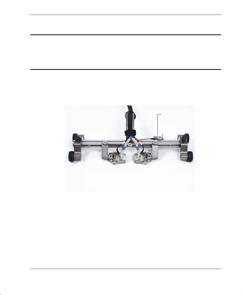
Location of marking
(see Table 1 on
page 2).
Labels and Symbols
Marking of the HST-Lite Scanner is shown in Figure i-1 on page 1. If the marking is
illegible, please contact Olympus.
Figure i-1 Marking location
Labels and Symbols 1
Page 6

DMTA-20045-01EN, Rev. A, October 2012
Table 1 Content of the marking
Marking:
Contains:
S/N The serial number.
The CE marking is a declaration that this product conforms to
all the applicable directives of the European Community. See
the Declaration of Conformity for details.
2 Labels and Symbols
The WEEE symbol indicates that the product must not be
disposed of as unsorted municipal waste, but should be
collected separately.
Page 7

DMTA-20045-01EN, Rev. A, October 2012
Important Information — Please Read Before Use
Intended Use
The HST-Lite Scanner is designed to perform nondestructive inspections on industrial
and commercial materials.
Do not use the HST-Lite Scanner for any purpose other than its intended use. It must
never be used to inspect or examine human or animal body parts.
Instruction Manual
This instruction manual contains essential information on how to use this Olympus
product safely and effectively. Before using this product, thoroughly review this
instruction manual, and use the product as instructed.
Keep this instruction manual in a safe, accessible location.
Important Information — Please Read Before Use 3
Page 8
DMTA-20045-01EN, Rev. A, October 2012
Instrument Compatibility
The HST-Lite Scanner is compatible with the ancillary Olympus equipment listed in
Table 2 on page 4. For a list of other compatible parts and accessories, refer to chapter
2 on page 29.
Using incompatible equipment could cause malfunction and/or equipment damage.
Table 2 Ancillary equipment
Equipment Description
OmniScan MX Phased array instrument
TomoScan FOCUS LT Phased array instrument (using the optional
C1-DE15F-BXM-0.30M [U8767107] encoder adaptor)
OmniScan MXU OmniScan software
OmniScan MX2 Phased array instrument (using the adaptor
OMNI-A2-ADP20 [U8775201] supplied with the
instrument)
TOFD wedges ST1 and ST2 type
Safety Symbols
The following safety symbols might appear on the instrument and in the instruction
manual:
General warning symbol:
This symbol is used to alert the user to potential hazards. All safety messages that
follow this symbol shall be obeyed to avoid possible harm.
4 Important Information — Please Read Before Use
Page 9
DMTA-20045-01EN, Rev. A, October 2012
High voltage warning symbol:
This symbol is used to alert the user to potential electric shock hazards greater
than 1000 volts. All safety messages that follow this symbol shall be obeyed to
avoid possible harm.
Safety Signal Words
The following safety symbols might appear in the documentation of the instrument:
The DANGER signal word indicates an imminently hazardous situation. It calls
attention to a procedure, practice, or the like, which, if not correctly performed or
adhered to, could result in death or serious personal injury. Do not proceed beyond a
DANGER signal word until the indicated conditions are fully understood and met.
The WARNING signal word indicates a potentially hazardous situation. It calls
attention to a procedure, practice, or the like, which, if not correctly performed or
adhered to, could result in death or serious personal injury. Do not proceed beyond a
WARNING signal word until the indicated conditions are fully understood and met.
The CAUTION signal word indicates a potentially hazardous situation. It calls
attention to an operating procedure, practice, or the like, which, if not correctly
performed or adhered to, could result in minor or moderate personal injury, material
damage, particularly to the product, destruction of part or all of the product, or loss of
data. Do not proceed beyond a
fully understood and met.
CAUTION signal word until the indicated conditions are
Important Information — Please Read Before Use 5
Page 10
DMTA-20045-01EN, Rev. A, October 2012
Note Signal Words
The following safety symbols could appear in the documentation of the instrument:
The IMPORTANT signal word calls attention to a note that provides important
information, or information essential to the completion of a task.
The NOTE signal word calls attention to an operating procedure, practice, or the like,
which requires special attention. A note also denotes related parenthetical
information that is useful, but not imperative.
The TIP signal word calls attention to a type of note that helps you apply the
techniques and procedures described in the manual to your specific needs, or
provides hints on how to effectively use the capabilities of the product.
Warnings
General Warnings
• Carefully read the instructions contained in this instruction manual prior to using
the instrument.
• Keep this instruction manual in a safe place for further reference.
• Follow the installation and operation procedures.
• It is imperative to respect the safety warnings on the instrument and in this
instruction manual.
• If the equipment is used in a manner not specified by the manufacturer, the
protection provided by the equipment could be impaired.
• Do not install substitute parts or perform any unauthorized modification to the
instrument.
6 Important Information — Please Read Before Use
Page 11

DMTA-20045-01EN, Rev. A, October 2012
WEEE Directive
In accordance with European Directive 2002/96/EC on Waste Electrical
and Electronic Equipment (WEEE), this symbol indicates that the
product must not be disposed of as unsorted municipal waste, but
should be collected separately. Refer to your local Olympus distributor
for return and/or collection systems available in your country.
Warranty Information
Olympus guarantees your Olympus product to be free from defects in materials and
workmanship for a specific period, and in accordance with conditions specified in the
Olympus NDT Terms and Conditions available at http://www.olympusims.com/en/terms/.
The Olympus warranty only covers equipment that has been used in a proper
manner, as described in this instruction manual, and that has not been subjected to
excessive abuse, attempted unauthorized repair, or modification.
Inspect materials thoroughly on receipt for evidence of external or internal damage
that might have occurred during shipment. Immediately notify the carrier making the
delivery of any damage, because the carrier is normally liable for damage during
shipment. Retain packing materials, waybills, and other shipping documentation
needed in order to file a damage claim. After notifying the carrier, contact Olympus
for assistance with the damage claim and equipment replacement, if necessary.
This instruction manual explains the proper operation of your Olympus product. The
information contained herein is intended solely as a teaching aid, and shall not be
used in any particular application without independent testing and/or verification by
the operator or the supervisor. Such independent verification of procedures becomes
increasingly important as the criticality of the application increases. For this reason,
Olympus makes no warranty, expressed or implied, that the techniques, examples, or
procedures described herein are consistent with industry standards, nor that they
meet the requirements of any particular application.
Olympus reserves the right to modify any product without incurring the
responsibility for modifying previously manufactured products.
Important Information — Please Read Before Use 7
Page 12

DMTA-20045-01EN, Rev. A, October 2012
Technical Support
Olympus is firmly committed to providing the highest level of customer service and
product support. If you experience any difficulties when using our product, or if it
fails to operate as described in the documentation, first consult the user’s manual, and
then, if you are still in need of assistance, contact our After-Sales Service. To locate the
nearest service center, visit the Service Centers page at: http://www.olympusims.com.
8 Important Information — Please Read Before Use
Page 13
DMTA-20045-01EN, Rev. A, October 2012
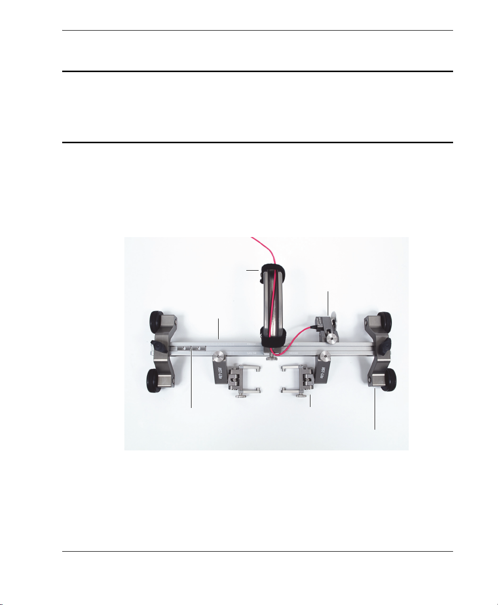
Frame bar
Handle
Dovetail nuts (2)
Probe holder (2)
Wheel encoder
Wheel block (2)
1. HST-Lite Scanner
The HST-Lite Scanner is a versatile pipe and plate scanner, which can be used to
inspect welds using TOFD and pulse-echo techniques.
The HST-Lite Scanner is composed of the following items (see Figure 1-1 on page 9):
Figure 1-1 The HST-Lite Scanner components
HST-Lite Scanner 9
Page 14
DMTA-20045-01EN, Rev. A, October 2012
1.1 Positioning the Frame Bar
The frame bar must be positioned differently according to the wedge model used:
• Stainless steel wedges (IHS)
• Rexolite wedges (IHC)
The engraving corresponding to the wedge model used must be facing upward. If it is
not the case, perform the following procedure.
To position the frame bar
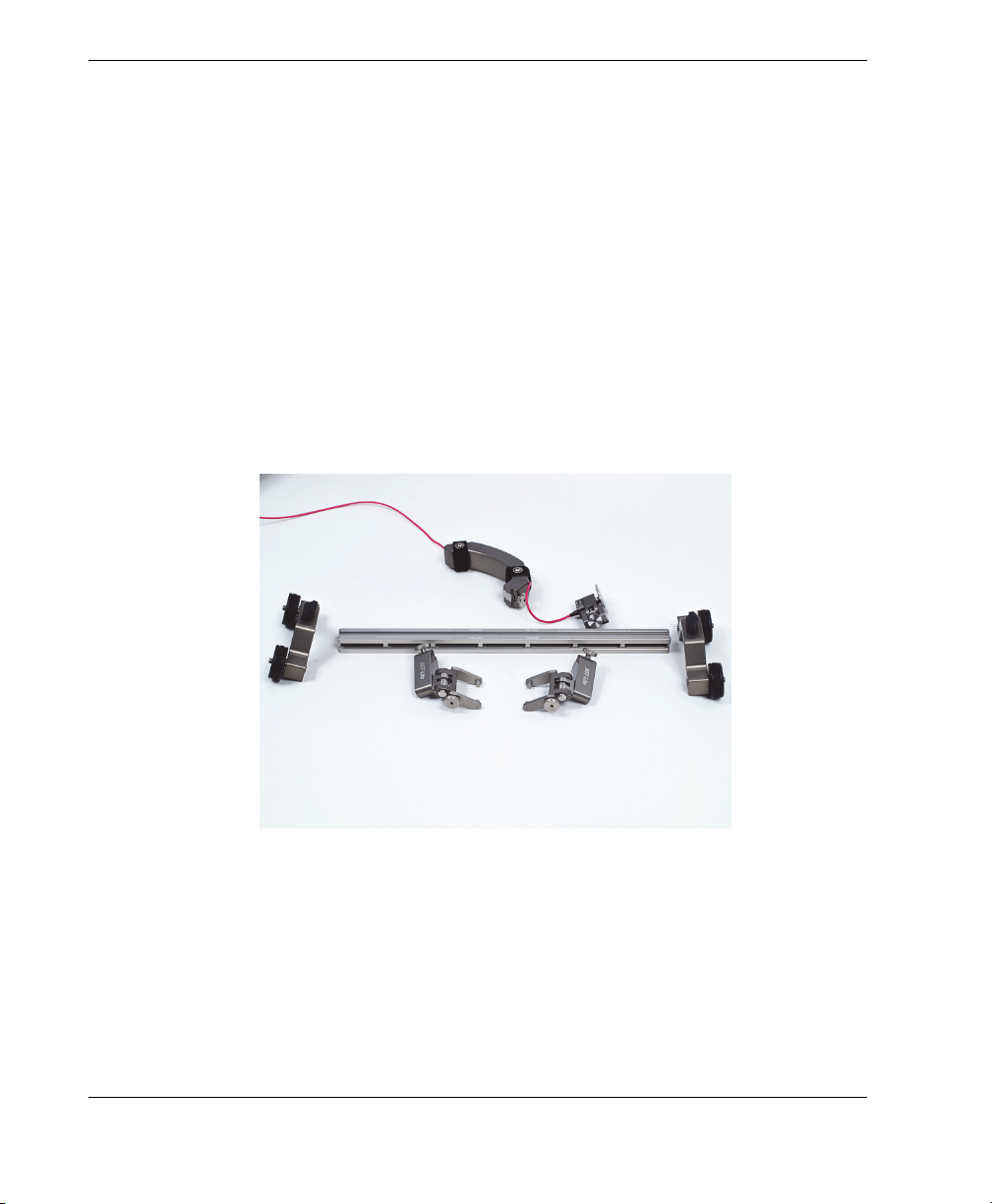
1. Loosen the wheel block, the probe holder, the handle, and the wheel encoder
thumbscrews, and then remove all the components from the frame bar (see
Figure 1-2 on page 10).
Figure 1-2 Disassembled scanner
2. Position the frame bar so the engraving corresponding to the wedge model used
IHS TOFD WEDGES or IHC TOFD WEDGES) is facing upward (see Figure 1-3 on
(
page 11).
10 HST-Lite Scanner
Page 15

DMTA-20045-01EN, Rev. A, October 2012
Engraving
corresponding to
the wedge model
Figure 1-3 Engraving on the frame bar
3. Reassemble the scanner.
1.2 Installing a Probe and a Wedge in a Probe Holder
To install a probe and a wedge in a probe holder
Before installing a new probe into a probe holder, make sure that there is enough
couplant between the probe face and the wedge.
1. Apply couplant on the probe face (see Figure 1-4 on page 12).
HST-Lite Scanner 11
Page 16

DMTA-20045-01EN, Rev. A, October 2012
Figure 1-4 Applying couplant on probe face
2. Install the probe on the wedge.
3. Loosen the yoke thumbscrew (see Figure 1-5 on page 12).
12 Chapter 1
Figure 1-5 Loosening yoke thumbscrew
Page 17

DMTA-20045-01EN, Rev. A, October 2012
Wedge Yoke arm guiding
pin
4. Install the probe and wedge assembly between the two yoke arms (see Figure 1-6
on page 13).
Figure 1-6 Wedge installed
5. Push the yoke arm in order to place the yoke arm guiding pin into the wedge side
hole (see Figure 1-6 on page 13).
6. Tighten the thumbscrew until it holds the yoke arm tight against the holder.
7. Repeat the procedure to install the other wedge.
1.3 Setting the Distance Between Beam Exit Points
To set the distance between beam exit points
1. According to the scan plan, determine the distance between the beam exit points
(for example, 40 mm).
2. Divide the distance value by two (for example, 20 mm).
3. Position the probe holders so their indicators point to the half value (for example,
20 mm) on the left- and right-hand side frame rulers (see Figure 1-7 on page 14
and Figure 1-8 on page 15).
HST-Lite Scanner 13
Page 18

DMTA-20045-01EN, Rev. A, October 2012
Indicator
Figure 1-7 Probe holder indicator
A millimeter appears as the distance between two short lines. The distance between
two long lines is 5 mm.
4. To make sure that the distance between beam exit points is properly set:
When using Rexolite wedges, measure the distance between the dots
engraved on yoke arms (see Figure 1-8 on page 15).
OR
When using stainless steel wedges, measure the distance between the vertical
lines engraved on wedges (see Figure 1-9 on page 15).
14 Chapter 1
Page 19

DMTA-20045-01EN, Rev. A, October 2012
Probe holder pointing to the half
value (for example, 20 mm)
Probe holder pointing to the half
value (for example, 20 mm)
Distance between beam exit
points (for example, 40 mm)
Dot on yoke armDot on yoke arm
Vertical line used to
measure distance between
beam exit points.
Figure 1-8 Distance between beam exit points (Rexolite wedges shown)
Figure 1-9 Vertical lines engraved on stainless steel wedges
HST-Lite Scanner 15
Page 20

DMTA-20045-01EN, Rev. A, October 2012
Wheel encoder thumbscrew
Slide the encoder
1.4 Positioning the Wheel Encoder
To position the wheel encoder
1. Loosen the wheel encoder thumbscrew (see Figure 1-10 on page 16).
2. Slide the wheel encoder to the desired position (see Figure 1-10 on page 16).
3. Tighten the wheel encoder thumbscrew.
Figure 1-10 Positioning the wheel encoder
1.5 Installing Tubing and Cables
To install tubing and cables
1. If you plan to use the offset probe configuration, assemble the HST-Lite Scanner
according to section 1.9 on page 26.
2. If required, install the preamplifier (see section 1.8 on page 24).
3. Connect the probe cables to the probes.
4. Cut four pieces of transparent tube. They should measure about 3.8 cm (1.5 in.)
long.
5. Install the four transparent tubes on the wedges (see Figure 1-11 on page 17).
6. Install a Y-fitting on each pair of transparent tubes (see Figure 1-11 on page 17).
16 Chapter 1
Page 21

DMTA-20045-01EN, Rev. A, October 2012
Y-fitting installed on wedge
tubes
Probe cable
Transparent tube
Figure 1-11 Transparent tubes installed on the wedges
7. Insert a Y-fitting in the blue irrigation tube (see Figure 1-12 on page 17).
Figure 1-12 Y-fitting inserted in the irrigation tube
HST-Lite Scanner 17
Page 22

DMTA-20045-01EN, Rev. A, October 2012
Hook and loop
strip
Y-fitting outside
the handle
8. Install the irrigation tube in the scanner handle, and then temporarily secure the
irrigation tube using the hook and loop strips (see Figure 1-13 on page 18).
Make sure the Y-fitting of the irrigation tube is outside the handle (see Figure 1-13 on
page 18).
18 Chapter 1
Figure 1-13 Securing the irrigation tube
9. Link the wedges to the irrigation tube using pieces of transparent tubes cut to the
required length (see Figure 1-14 on page 19).
Page 23

Figure 1-14 Irrigation tube linked to the wedges
1.6 Installing the Cable Sheath
DMTA-20045-01EN, Rev. A, October 2012
To install the cable sheath
1. Unfasten the handle hook and loop strips.
2. Bundle up the probe cables, wheel encoder cable, irrigation tube, and
preamplifier cables (if installed).
3. Install the draw-in tool on the cable and tube bundle. The pointed end of the
draw-in tool should point away from the scanner (see Figure 1-15 on page 20).
HST-Lite Scanner 19
Page 24

DMTA-20045-01EN, Rev. A, October 2012
Pointed end pointing away
from the scanner
Figure 1-15 Draw-in tool installed on cable and tube bundle
4. Install the cable sheath over the draw-in tool, and then slide the tool to install the
cable sheath (see Figure 1-16 on page 20).
20 Chapter 1
Figure 1-16 Cable sheath installed on the draw-in tool
Page 25

DMTA-20045-01EN, Rev. A, October 2012
To prevent the draw-in tool from slipping out of the cable sheath, place your fingers
under the tool and the sheathing (see Figure 1-17 on page 21).
Figure 1-17 Fingers placed under the draw-in tool
5. Position the cable and tube bundle in the scanner handle, and then fasten the
hook and loop strips (see Figure 1-18 on page 22).
HST-Lite Scanner 21
Page 26

DMTA-20045-01EN, Rev. A, October 2012
Figure 1-18 Cable and tube bundle in the scanner handle
1.7 Scanner Wheels
The HST-Lite Scanner is equipped with four wheels. Two additional wheels can be
installed for offset configuration. For more details about offset configuration, see
section 1.9 on page 26.
To replace a scanner wheel
1. Block the wheel shaft using the hexagonal key (see Figure 1-19 on page 23).
22 Chapter 1
Page 27

DMTA-20045-01EN, Rev. A, October 2012
Blocking the
wheel shaft
Non-threaded flange
Figure 1-19 Blocking the wheel shaft
2. Unscrew the wheel manually, and then remove the wheel (see Figure 1-20 on
page 23).
Figure 1-20 Installing a replacement wheel
HST-Lite Scanner 23
Page 28

DMTA-20045-01EN, Rev. A, October 2012
Dovetail nut (2)
Back channel
When installing a replacement wheel, make sure that the non-threaded flange faces
the wheel block. If the wheel is not installed properly, the wheel threads will be
damaged.
3. Block the wheel shaft with your fingers, and then manually screw on the
replacement wheel.
4. Hold the wheel shaft in place using the hexagonal key, and then slightly tighten
the wheel.
1.8 Installing a Preamplifier
Perform the following procedure to install the optional preamplifier (P/N: 5682-KIT02
[U8779091]).
To install a preamplifier
1. Remove one of the wheel blocks.
2. Remove both dovetail nuts from the frame bar, and then insert them in the back
channel (see Figure 1-21 on page 24).
24 Chapter 1
Figure 1-21 Inserting dovetail nuts in the frame bar back channel
Page 29

DMTA-20045-01EN, Rev. A, October 2012
Lock washer on
thumbscrew
Preamplifier
bracket HSMT-ABRK5682
[U8779089]
(included in 5682KIT02 package)
3. Reinstall the wheel block.
4. Insert a lock washer on each preamplifier bracket thumbscrew (see Figure 1-22 on
page 25).
To prevent thread damage, do not overtighten the preamplifier bracket thumbscrews.
5. Secure the preamplifier bracket to the dovetail nuts using the thumbscrews (see
Figure 1-22 on page 25).
Figure 1-22 Securing the preamplifier bracket
6. Install the preamplifier in the bracket, and then secure the preamplifier using the
hook and loop strips (see Figure 1-23 on page 26).
HST-Lite Scanner 25
Page 30

DMTA-20045-01EN, Rev. A, October 2012
Figure 1-23 Preamplifier installed
1.9 Offset Probe Configuration
When an obstacle prevents you from placing the weld to be inspected between the
wheels, we suggest you use the offset configuration.
To configure the scanner for offset inspection
1. Install the scanner components as shown in Figure 1-24 on page 27.
26 Chapter 1
Page 31

DMTA-20045-01EN, Rev. A, October 2012
Two wheels installed
Figure 1-24 Offset configuration
2. Adjust the distance between beam exit points according to step 4 on page 14.
To prevent the scanner from falling off during the inspection, you must add two
magnetic wheels to the inner wheel block. Additional magnetic wheels are sold
separately.
When installing an additional wheel on a shaft, make sure that the threaded flange of
the second wheel faces the wheel block.
3. Install the additional wheels (see Figure 1-25 on page 28):
HST-Lite Scanner 27
Page 32

DMTA-20045-01EN, Rev. A, October 2012
Figure 1-25 Installing an additional wheel
a) Block the wheel shaft with your fingers, and then manually screw on the
wheel. The wheel threaded flange must face the wheel block.
b) Hold the shaft in place using the hexagonal key, and then slightly tighten the
wheel.
c) Repeat the step for the other wheel.
28 Chapter 1
Page 33

DMTA-20045-01EN, Rev. A, October 2012
2. Parts and Accessories
This chapter describes the accessories delivered with the HST-Lite Scanner and
presents a list of spare parts that can be used with the scanner.
2.1 Standard Accessories
The HST-Lite Scanner comes standard with:
• Frame bar with handle.
• Four magnetic wheels.
• OmniScan-compatible, waterproof, spring-loaded wheel encoder with 5 m cable.
• Two spring-loaded arms (SLA) with TOFD–P/E yokes (31.75 mm wide and 5 mm
diameter buttons).
• Irrigation tubing and accessories.
• Cable sheath.
• Carrying case.
Probes, wedges, and cables are not included with the basic HST-Lite Scanner.
Parts and Accessories 29
Page 34

DMTA-20045-01EN, Rev. A, October 2012
2.2 Optional Accessories
Table 3 HST-Lite Scanner optional accessories
Description Part number
5682 remote preamplifier kit 5682-KIT02 (U8779091)
Couplant-feed unit WTR-SPRAYER-8L (U8775001)
TomoScan FOCUS LT encoder
cable adaptor
Plastic wheel CHAINSCAN-A-PWHEEL (U8775189)
Magnetic wheel CHAINSCAN-A-MWHEEL (U8779383)
Replacement encoder HST-Lite-SP-ENC (U8775277)
Extra handle HST-Lite-A-Handle (U8775278)
Extra pair of spring loaded
probe holders for TOFD
inspection compatible with
HST-Lite Scanner. Yokes are
31.75 mm wide and 23.5 mm
long with 5 mm buttons.
Irrigation tubes and fittings for
HST-Lite Scanner. Same
content as in the basic HST-Lite
Scanner package.
C1-DE15F-BXM-0.30M (U8767107)
HST-Lite-A-PH-TOFD (U8775279)
HST-Lite-SP-IRRIGATION (U8775281)
30 Chapter 2
Page 35

DMTA-20045-01EN, Rev. A, October 2012
3. Specifications
This chapter presents the general specifications for the HST-Lite Scanner.
Table 4 HST-Lite Scanner specifications
Length in scan
axis (mm)
125 385
a. 67 mm without handle
Width
(mm)
Height
(mm)
a
100
Wei ght
(kg)
1.3 9
Encoder
resolution
(steps/mm)
Specifications 31
Page 36

DMTA-20045-01EN, Rev. A, October 2012
32 Chapter 3
Page 37

DMTA-20045-01EN, Rev. A, October 2012
List of Figures
Figure i-1 Marking location .................................................................................................. 1
Figure 1-1 The HST-Lite Scanner components ................................................................... 9
Figure 1-2 Disassembled scanner ....................................................................................... 10
Figure 1-3 Engraving on the frame bar ............................................................................. 11
Figure 1-4 Applying couplant on probe face .................................................................... 12
Figure 1-5 Loosening yoke thumbscrew ........................................................................... 12
Figure 1-6 Wedge installed .................................................................................................. 13
Figure 1-7 Probe holder indicator ...................................................................................... 14
Figure 1-8 Distance between beam exit points (Rexolite wedges shown) ................... 15
Figure 1-9 Vertical lines engraved on stainless steel wedges ......................................... 15
Figure 1-10 Positioning the wheel encoder ......................................................................... 16
Figure 1-11 Transparent tubes installed on the wedges .................................................... 17
Figure 1-12 Y-fitting inserted in the irrigation tube ........................................................... 17
Figure 1-13 Securing the irrigation tube ............................................................................. 18
Figure 1-14 Irrigation tube linked to the wedges ............................................................... 19
Figure 1-15 Draw-in tool installed on cable and tube bundle .......................................... 20
Figure 1-16 Cable sheath installed on the draw-in tool .................................................... 20
Figure 1-17 Fingers placed under the draw-in tool ........................................................... 21
Figure 1-18 Cable and tube bundle in the scanner handle ............................................... 22
Figure 1-19 Blocking the wheel shaft ................................................................................... 23
Figure 1-20 Installing a replacement wheel ........................................................................ 23
Figure 1-21 Inserting dovetail nuts in the frame bar back channel ................................. 24
Figure 1-22 Securing the preamplifier bracket ................................................................... 25
Figure 1-23 Preamplifier installed ........................................................................................ 26
Figure 1-24 Offset configuration .......................................................................................... 27
Figure 1-25 Installing an additional wheel ......................................................................... 28
List of Figures 33
Page 38

DMTA-20045-01EN, Rev. A, October 2012
34 List of Figures
Page 39

DMTA-20045-01EN, Rev. A, October 2012
List of Tables
Table 1 Content of the marking .......................................................................................... 2
Table 2 Ancillary equipment ............................................................................................... 4
Table 3 HST-Lite Scanner optional accessories ............................................................... 30
Table 4 HST-Lite Scanner specifications .......................................................................... 31
List of Tables 35
Page 40

DMTA-20045-01EN, Rev. A, October 2012
36 List of Tables
Page 41

Index
DMTA-20045-01EN, Rev. A, October 2012
A
accessories 29
optional accessories 30
standard accessories 29
additional wheels 27
ancillary equipment See compatibility, scanner
arm, yoke 13, 29
B
bar, frame 9, 29
engraving 11
positioning 10
rulers 13
beam exit points 15
distance 13
Rexolite wedges 14
stainless steel wedges 14
block, wheel 9
blue tube See irrigation tube
bracket, preamplifier 25
C
cable
installation 16
probe 17
sheath 19, 29
carrying case 29
caution notes
additional wheel installation 27
couplant on probe 11
incompatible equipment 4
wheel replacement 24
CE marking 2
compatibility, scanner 4
OmniScan MX 4
OmniScan MX2 4
OmniScan MXU 4
TOFD wedges 4
TomoScan FOCUS LT 4
components, scanner See scanner components
conduit See sheath, cable
configuration, offset probe 26, 27
couplant 11, 12
D
danger note, scanner intended use 3
distance, beam exit points 13, 15
dovetail nuts 9, 24
draw-in tool 19, 20
pointed end 20
E
encoder, wheel 9, 29
positioning 16
F
fittings, Y- 17, 18
frame bar 9, 29
engraving 11
positioning 10
rulers 13
G
guiding pin, yoke arm 13
H
handle 9
Index 37
Page 42

DMTA-20045-01EN, Rev. A, October 2012
hexagonal key 22
holder, probe 9
hook and loop strips 18
HST-Lite Scanner See scanner
I
IHC 10
IHS 10
installing
additional wheels 27
cable sheath 19
preamplifier 24
probe in probe holder 11
tubing and cables 16
instruction manual 3
instrument See scanner
intended use, scanner 3
irrigation tube 17, 29
K
key, hexagonal 22
L
lock washers 25
M
magnetic wheels See wheels
manual, instruction 3
marking
content 2
location 1
N
note signal words 6
notes
irrigation tube Y-fitting 18
probes and wedges not included 29
ruler reading 14
nuts, dovetail 9, 24
O
offset probe configuration 26, 27
Olympus technical support 8
optional accessories 30
P
parts 29
points, beam exit 15
distance 13
Rexolite wedges 14
stainless steel wedges 14
positioning
frame bar 10
wheel encoder 16
preamplifier 26
bracket 25
dovetail nuts 9, 24
installation 24
probe
cable 17
holder 9
installation 11
offset configuration 26, 27
R
removing a wheel 23
replacing scanner wheels 22
rulers 13
S
safety
signal words 5
symbols 4
scanner
compatibility 4
OmniScan MX 4
OmniScan MX2 4
OmniScan MXU 4
TOFD wedges 4
TomoScan FOCUS LT 4
components 9
dovetail nuts 9, 24
frame bar 9, 29
handle 9
probe holder 9
wheel block 9
wheel encoder 9, 29
description 9
intended use 3
marking
content 2
location 1
serial number 2
38 Index
Page 43

DMTA-20045-01EN, Rev. A, October 2012
specifications 31
wheels 22
removal 23
replacement 22
shaft 23
serial number 2
setting distance between beam exit points 13
sheath, cable 19, 29
signal words
note 6
safety 5
specifications 31
standard accessories 29
strips, hook and loop 18
support information 8
symbols
CE 2
WEEE 2
T
technical support 8
thumbscrews
lock washers 25
preamplifier bracket 25
yoke 12
tip, draw-in tool usage 21
tools
draw-in tool 19, 20
pointed end 20
hexagonal key 22
transparent tubes 17, 18, 19
tubing
installation 16
irrigation tube 17, 29
transparent tubes 17, 18, 19
U
use, scanner intended 3
V
velcro See hook and loop strips
W
warnings, general 6
warranty information 7
washers, lock 25
waste electrical and electronic equipment
(WEEE) 7
wedges
Rexolite (IHC) 10
stainless steel (IHS) 10
WEEE directive 2, 7
wheel block 9
wheel encoder 9, 29
positioning 16
wheels 22, 29
additional wheel installation 27
removal 23
replacement 22
shaft 23
Y
yellow tool See draw-in tool
Y-fittings 17, 18
yoke
arm 13, 29
guiding pin 13
thumbscrew 12
Index 39
Page 44

DMTA-20045-01EN, Rev. A, October 2012
40 Index
 Loading...