

Olympus GLIDER User Manual

GLIDER
Two-Axis Flat Panel Scanner
User’s Manual
DMTA029-01EN — Rev. E
December 2017
This instruction manual contains essential information on how to use this Olympus product safely and effectively.
Before using this product, thoroughly review this instruction manual. Use the product as instructed.
Keep this instruction manual in a safe, accessible location.

Olympus Scientific Solutions Americas, 48 Woerd Avenue, Waltham, MA 02453, USA
Copyright © 2007, 2014, 2016, 2017 by Olympus. All rights reserved. No part of this
publication may be reproduced, translated, or distributed without the express written
permission of Olympus.
This document was prepared with particular attention to usage to ensure the accuracy of the
information contained therein, and corresponds to the version of the product manufactured
prior to the date appearing on the title page. There could, however, be some differences
between the manual and the product if the product was modified thereafter.
The information contained in this document is subject to change without notice.
Part number: DMTA029-01EN
Rev. E
December 2017
Printed in Canada
All brands are trademarks or registered trademarks of their respective owners and third
party entities.

DMTA029-01EN, Rev. E, December 2017
Table of Contents
Labels and Symbols ........................................................................................... 1
Important Information — Please Read Before Use ..................................... 3
Intended Use .......................................................................................................................... 3
Instruction Manual ................................................................................................................ 3
Loose Parts .............................................................................................................................. 4
Scanner Compatibility .......................................................................................................... 4
Presence of Visual Interferences or Phantom Spots ......................................................... 5
Safety Symbols ....................................................................................................................... 5
Safety Signal Words ............................................................................................................... 6
Note Signal Words ................................................................................................................. 7
Safety ....................................................................................................................................... 7
Warnings ................................................................................................................................. 7
Equipment Disposal .............................................................................................................. 8
CE (European Community) ................................................................................................. 8
WEEE Directive ...................................................................................................................... 8
Warranty Information ........................................................................................................... 9
Technical Support .................................................................................................................. 9
Introduction ...................................................................................................... 11
1. Overview ..................................................................................................... 13
2. Scanner Assembly and Setup .................................................................. 17
2.1 Assembling the Scanner ........................................................................................... 17
2.2 Part Replacement and Adjustment ........................................................................ 18
2.2.1 Replacing a Mounting Pod ........................................................................... 18
2.2.2 Installing a Vacuum Generator with Pods ................................................. 19
2.2.3 Adjusting the Orientation of the Probe Holder ......................................... 28
Table of Contents iii

DMTA029-01EN, Rev. E, December 2017
2.2.4 Installing Springs on the Bearing Arm ........................................................ 30
2.2.5 Replacing a Conventional Ultrasonic Transducer ..................................... 33
2.2.6 Replacing a Phased Array Probe ................................................................. 35
2.2.7 Changing an Encoder .................................................................................... 37
2.2.8 Changing the Length of an Axis .................................................................. 38
2.3 Scanner Installation on the Inspection Surface ..................................................... 41
2.3.1 Installing a Scanner with Suction-Cup Pods .............................................. 41
2.3.2 Installing a Scanner with Magnetic Pods .................................................... 44
2.4 Setting Up the Scanner for Inspection .................................................................... 46
3. Operating the Scanner .............................................................................. 49
4. Specifications .............................................................................................. 53
5. Accessories and Spare Parts ..................................................................... 57
5.1 Yokes ........................................................................................................................... 57
5.2 Couplant-Feed Units ................................................................................................ 58
5.3 Connector Reference ................................................................................................. 59
5.4 Spare Parts .................................................................................................................. 59
6. Maintenance ................................................................................................ 65
6.1 Preventive Maintenance ........................................................................................... 65
6.2 Unit Cleaning ............................................................................................................. 65
List of Figures ................................................................................................... 67
List of Tables ..................................................................................................... 69
Index ................................................................................................................... 71
Table of Contentsiv

List of Abbreviations
A.M. according to model
CE European Community
EC eddy current
ECA eddy current array
FSW friction stir weld
ID internal diameter
N/A not applicable
NL normal liters
OD outside diameter
OEM original equipment manufacturer
P/N part number
PA phased array
SCFM standard cubic feet per minute
UT ultrasonic testing
WEEE waste electrical and electronic equipment
DMTA029-01EN, Rev. E, December 2017
List of Abbreviations v

DMTA029-01EN, Rev. E, December 2017
List of Abbreviationsvi
DMTA029-01EN, Rev. E, December 2017
Rating label
Labels and Symbols
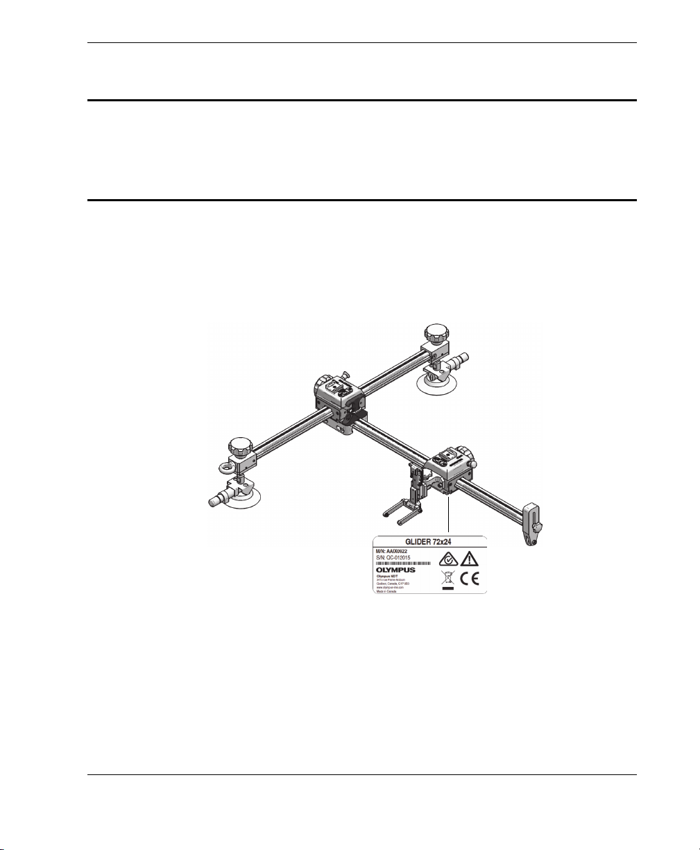
Safety-related labels and symbols are attached to the GLIDER scanner at the location
shown in Figure i-1 on page 1, with contents listed in Table 1 on page 2. If any or all of
the labels or symbols are missing or illegible, please contact Olympus.
Figure i‑1 Location of label on the GLIDER scanner
Labels and Symbols 1
DMTA029-01EN, Rev. E, December 2017
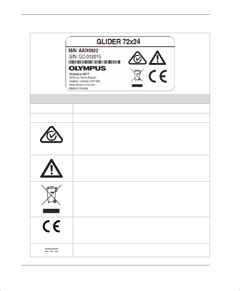
Table 1 Content of the rating label
Content
M/N
S/N
The model number is an eight (8) digit number.
The serial number is an eight (8) digit number.
The regulatory compliance mark (RCM) label indicates that
the product complies with all applicable standards, and has
been registered with the Australian Communications and
Media Authority (ACMA) for placement on the Australian
market.
The warning symbol indicates that the user must read the
user’s manual in order to find out the nature of the potential
hazards and any actions to avoid them.
The WEEE symbol indicates that the product must not be
disposed of as unsorted municipal waste, but should be
collected separately.
The CE marking is a declaration that this product conforms to
all the applicable directives of the European Community. See
the Declaration of Conformity for details. Contact your Olympus
representative for more information.
The direct current symbol.
Labels and Symbols2

DMTA029-01EN, Rev. E, December 2017
WARNING
IMPORTANT
Important Information — Please Read Before Use
Intended Use
The GLIDER scanner is designed to perform nondestructive inspections on industrial
and commercial materials.
Do not use the GLIDER scanner for any purpose other than its intended use. It must
never be used to inspect or examine human or animal body parts.
Instruction Manual
This instruction manual contains essential information on how to use this Olympus
product safely and effectively. Before using this product, thoroughly review this
instruction manual. Use the product as instructed.
Keep this instruction manual in a safe, accessible location.
Some of the details of components illustrated in this manual may differ from the
components installed on your instrument. However, the principles remain the same.
Important Information — Please Read Before Use 3
DMTA029-01EN, Rev. E, December 2017
WARNING
CAUTION
Loose Parts
The user is responsible for ensuring that no scanner parts have come loose or are lost
in critical mechanisms being inspected or maintained, especially in the case of aircraft.
Conduct a proper inspection before and after use to prevent foreign-object debris
(FOD) that could potentially cause equipment damage, injuries, or loss of life.
Scanner Compatibility
The GLIDER scanner is compatible with the Olympus ancillary equipment listed in
Table 2 on page 4.
Always use equipment and accessories that meet Olympus specifications. Using
incompatible equipment could cause equipment malfunction and/or damage, or
human injury.
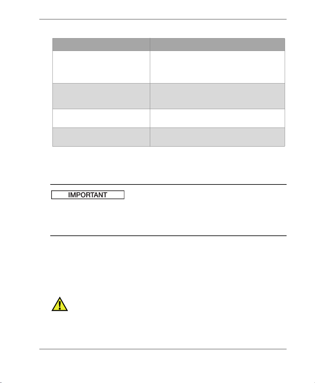
Table 2 Ancillary equipment
Equipment Description
OmniScan PA and FOCUS LT Several types of phased array instrument model
can be used (may require one of the encoder cable
adaptors listed below).
Phased array probe and wedge Several models used. See Table 6 on page 57 for
optional holder models required according to
wedge models.
Important Information — Please Read Before Use4
DMTA029-01EN, Rev. E, December 2017
IMPORTANT
Table 2 Ancillary equipment (continued)
Equipment Description
P/N: U8775201 Scanner interface adaptor to connect scanner
encoder cables with DE15 connector to OmniScan
MX2, SX and FOCUS PX with LEMO connector
scanner interface.
P/N: U8780329 Scanner interface adaptor to connect scanner
encoder cables with LEMO connector to OmniScan
MX with DE15 connector scanner interface.
P/N: U8769010 0.3 m long adaptor LEMO female to Bendix male
linking LEMO encoder cable to FOCUS LT.
P/N: U8767107 0.3 m long adaptor DE15 female to Bendix male
linking DE15 encoder cable to FOCUS LT.
Presence of Visual Interferences or Phantom Spots
In a situation of physical proximity to powerful electromagnetic radiators, visual
interferences or phantom spots may be present. These interferences are temporary
and their persistence is not permanent in comparison with physical features of the
inspected part.
Safety Symbols
The following safety symbols might appear on the product and in the instruction
manual:
General warning symbol
This symbol is used to alert the user to potential hazards. All safety messages that
follow this symbol shall be obeyed to avoid possible harm or material damage.
Important Information — Please Read Before Use 5

DMTA029-01EN, Rev. E, December 2017
DANGER
WARNING
CAUTION
Shock hazard caution symbol
This symbol is used to alert the user to potential electric shock hazards. All safety
messages that follow this symbol shall be obeyed to avoid possible harm.
Magnetic field warning symbol
This symbol is used to alert the user to potentially strong magnetic fields. All
safety messages that follow this symbol shall be obeyed to avoid possible harm.
Safety Signal Words
The following safety signal words might appear in the documentation of the product:
The DANGER signal word indicates an imminently hazardous situation. It calls
attention to a procedure, practice, or the like that if not correctly performed or
adhered to will result in death or serious personal injury. Do not proceed beyond a
DANGER signal word until the indicated conditions are fully understood and met.
The WARNING signal word indicates a potentially hazardous situation. It calls
attention to a procedure, practice, or the like that if not correctly performed or
adhered to could result in death or serious personal injury. Do not proceed beyond a
WARNING signal word until the indicated conditions are fully understood and met.
The CAUTION signal word indicates a potentially hazardous situation. It calls
attention to an operating procedure, practice, or the like that if not correctly
performed or adhered to may result in minor or moderate personal injury, material
damage, particularly to the product, destruction of part or all of the product, or loss of
data. Do not proceed beyond a CAUTION signal word until the indicated conditions
are fully understood and met.
Important Information — Please Read Before Use6
DMTA029-01EN, Rev. E, December 2017
IMPORTANT
NOTE
TIP
WARNING
Note Signal Words
The following note signal words could appear in the documentation of the product:
The IMPORTANT signal word calls attention to a note that provides important
information, or information essential to the completion of a task.
The NOTE signal word calls attention to an operating procedure, practice, or the like,
which requires special attention. A note also denotes related parenthetical
information that is useful, but not imperative.
The TIP signal word calls attention to a type of note that helps you apply the
techniques and procedures described in the manual to your specific needs, or
provides hints on how to effectively use the capabilities of the product.
Safety
Before turning on the instrument, verify that the correct safety precautions have been
taken (see the following warnings). In addition, note the external markings on the
instrument, which are described under “Safety Symbols”.
Warnings
General Warnings
• Carefully read the instructions contained in this instruction manual prior to
• Keep this instruction manual in a safe place for further reference.
turning on the instrument.
Important Information — Please Read Before Use 7
DMTA029-01EN, Rev. E, December 2017
• Follow the installation and operation procedures.
• It is imperative to respect the safety warnings on the instrument and in this
instruction manual.
• If the equipment is used in a manner not specified by the manufacturer, the
protection provided by the equipment could be impaired.
• Do not install substitute parts or perform any unauthorized modification to the
instrument.
Equipment Disposal
Before disposing of the GLIDER scanner, check your local laws, rules, and
regulations, and follow them accordingly.
CE (European Community)
This device complies with the requirements of both directive
2014/30/EU concerning electromagnetic compatibility and directive
2014/35/EU concerning low voltage. The CE marking indicates
compliance with the above directives.
WEEE Directive
Important Information — Please Read Before Use8
In accordance with European Directive 2012/19/EU on Waste Electrical
and Electronic Equipment (WEEE), this symbol indicates that the
product must not be disposed of as unsorted municipal waste, but
should be collected separately. Refer to your local Olympus distributor
for return and/or collection systems available in your country.

DMTA029-01EN, Rev. E, December 2017
Warranty Information
Olympus guarantees your Olympus product to be free from defects in materials and
workmanship for a specific period, and in accordance with conditions specified in the
Olympus Scientific Solutions Americas Inc. Terms and Conditions available at
http://www.olympus-ims.com/en/terms/.
The Olympus warranty only covers equipment that has been used in a proper
manner, as described in this instruction manual, and that has not been subjected to
excessive abuse, attempted unauthorized repair, or modification.
Inspect materials thoroughly on receipt for evidence of external or internal damage
that might have occurred during shipment. Immediately notify the carrier making the
delivery of any damage, because the carrier is normally liable for damage during
shipment. Retain packing materials, waybills, and other shipping documentation
needed in order to file a damage claim. After notifying the carrier, contact Olympus
for assistance with the damage claim and equipment replacement, if necessary.
This instruction manual explains the proper operation of your Olympus product. The
information contained herein is intended solely as a teaching aid, and shall not be
used in any particular application without independent testing and/or verification by
the operator or the supervisor. Such independent verification of procedures becomes
increasingly important as the criticality of the application increases. For this reason,
Olympus makes no warranty, expressed or implied, that the techniques, examples, or
procedures described herein are consistent with industry standards, nor that they
meet the requirements of any particular application.
Olympus reserves the right to modify any product without incurring the
responsibility for modifying previously manufactured products.
Technical Support
Olympus is firmly committed to providing the highest level of customer service and
product support. If you experience any difficulties when using our product, or if it
fails to operate as described in the documentation, first consult the user’s manual, and
then, if you are still in need of assistance, contact our After-Sales Service. To locate the
nearest service center, visit the Service Centers page at: http://www.olympusims.com.
Important Information — Please Read Before Use 9

DMTA029-01EN, Rev. E, December 2017
Important Information — Please Read Before Use10

DMTA029-01EN, Rev. E, December 2017
Introduction
This manual contains instructions on assembling, installing, and operating the
GLIDER scanner.
The GLIDER scanner has two axes of motion: the X-axis and the Y-axis. Encoders, one
on each axis, provide precise position information. The scanner is used for inspecting
slightly curved and flat surfaces. It uses a single probe or transducer, which can vary
in type:
• A conventional ultrasonic (UT) transducer or phased array ultrasonic (PA) probe.
• An eddy current (EC) probe or eddy current array (ECA) probe. The probe holder
for the eddy current type of probe is not included with the scanner, however.
Typical applications include the inspection of plates and airplane fuselages for
delamination, cracks, and corrosion, as well as the inspection of friction stir welds
(FSW) on aluminum. The scanner is well suited for raster scanning with a single probe
or transducer.
Commonly inspected materials include composites, aluminum, and carbon steel.
Suction-cup mounting pods are used to hold the scanner against the inspection
surface. On ferromagnetic materials such as steel, however, optional magnetic
mounting pods are used to hold the scanner.
To help users understand and safely use the scanner, this manual provides the
following subject matter:
• An overview of main components
• Setup and operation
•Maintenance
• Specifications
Introduction 11

DMTA029-01EN, Rev. E, December 2017
Introduction12

DMTA029-01EN, Rev. E, December 2017
1. Overview
This chapter provides an overview of the components on the GLIDER scanner.
The scanner’s X-axis is secured to the inspection surface by either suction cups or
magnetic pods (sold separately). The probe (or transducer) holder moves along the Yaxis. Between inspection passes along one of the axes, the probe or transducer can be
either incremented in fixed steps or moved freely along the other axis to perform a
raster scan.
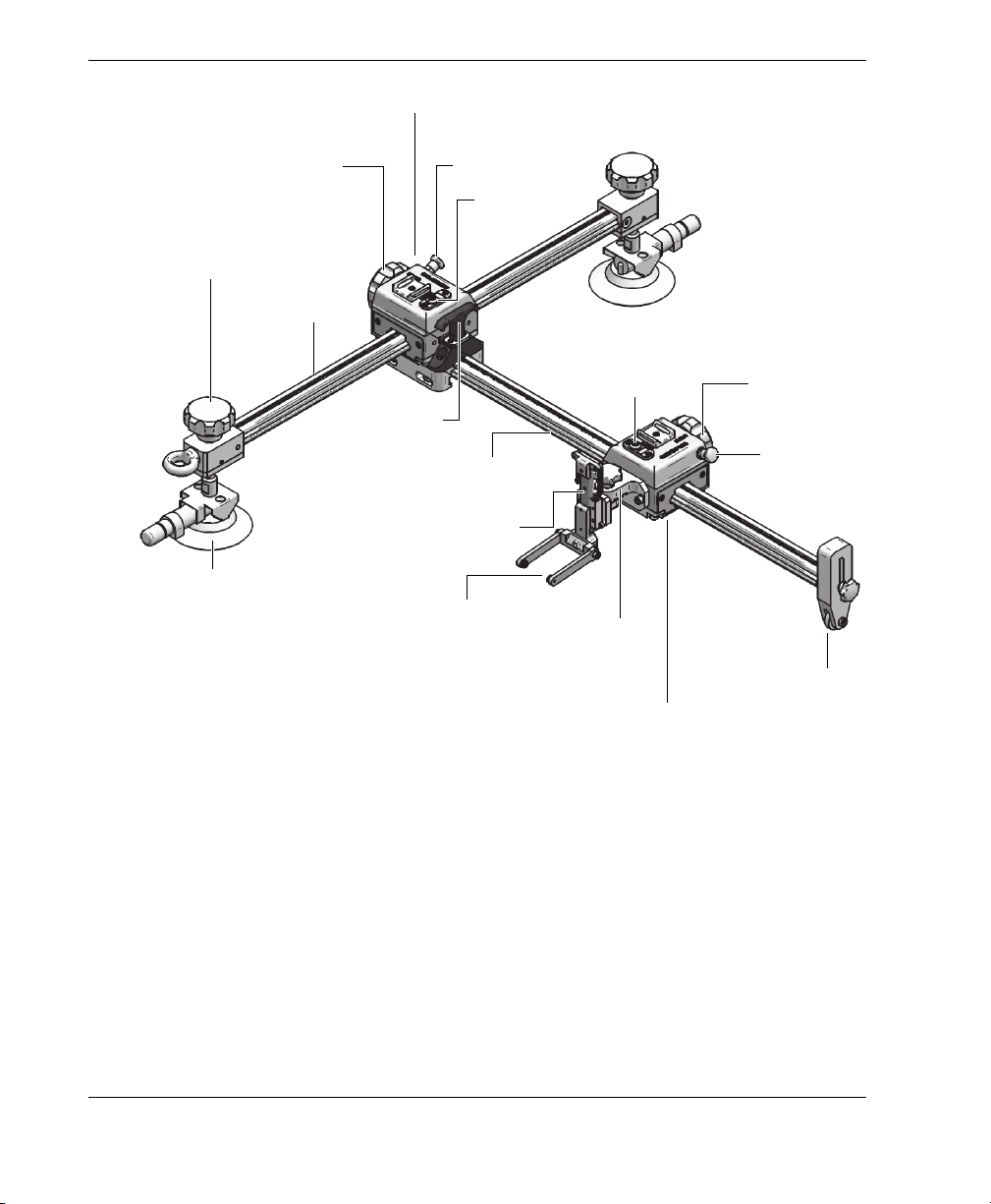
The GLIDER scanner is made up of three main component groups:
• Mounting pods (either suction-cup pods or magnetic pods)
• X-axis encoder module
• Y-axis encoder module
The elements of these main groups are illustrated in Figure 1-1 on page 14; a detailed
description follows.
Overview 13
DMTA029-01EN, Rev. E, December 2017
Mounting pod
X-axis encoder module
Y-axis encoder module
Pivot lock for mounting
pod
X-axis
X-axis increment knob
X-axis lock
Y- ax is
Y- ax is
increment knob
Y- ax is
lock
Y-a xi s
support
Probe or transducer
holder
Mounting bracket for
probe or transducer
holder
Encoder 1
Encoder 2
Y-axis quick release
Bearing arm
Mounting pods
Chapter 114
The X-axis is attached to two mounting pods that hold the scanner against the
inspection surface. Depending on the material to inspect, one of the following pod
types can be used (see Figure 1-2 on page 15): suction-cup pods (manual type
included) or magnetic pods (optional).
An optional vacuum generator with special suction cups is also available (for
more details, see “Installing a Vacuum Generator with Pods” on page 19).
Figure 1‑1 Scanner components

DMTA029-01EN, Rev. E, December 2017
Figure 1‑2 Mounting pod models: optional magnetic (left) and manual suction
cup (right)
The following features are common to both the X-axis and the Y-axis encoder
modules:
• Wheels, which are mounted on bearings that provide a smooth movement during
the entire axis stroke.
• Encoders, which measure the probe position along the axes (encoder resolution is
marked on the module).
• Locking devices, which allow each axis to be locked.
• Increment knobs, which can be set to either increment the axes in 4 mm steps, or
to provide a free-running motion (see Figure 1-3 on page 15).
Figure 1‑3 Increment‑knob positions: incrementing (left) and free‑running (right)
Overview 15
DMTA029-01EN, Rev. E, December 2017
X-axis encoder module
In addition to the common features listed above, the X-axis encoder module is
equipped with a quick-release device for the Y-axis, which allows you to
position the Y-axis with respect to the X-axis.
Y-axis encoder module
In addition to the common features listed above, the Y-axis encoder module
includes a mounting surface for the probe (or transducer) holder.
To help stabilize the Y-axis, one end rests on a height-adjustable support that
is equipped with a wheel.
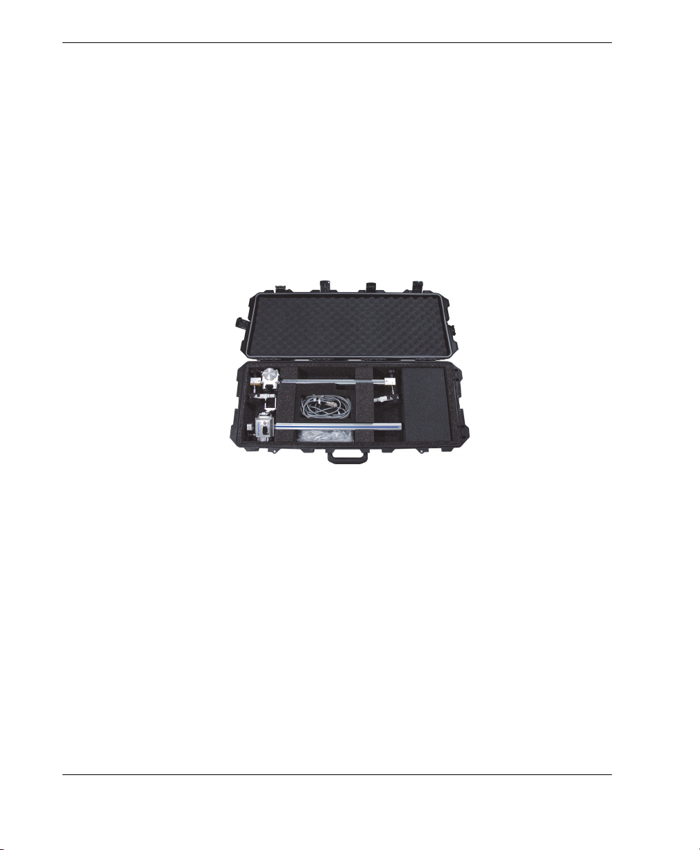
The scanner components are stored in a custom case (see Figure 1-4 on page 16).
Figure 1‑4 Scanner components stored in the case
Chapter 116
DMTA029-01EN, Rev. E, December 2017
2. Scanner Assembly and Setup
The GLIDER scanner is designed for ease of assembly, servicing, installation, and
setup.
2.1 Assembling the Scanner
To assemble the scanner, simply insert the Y-axis into the X-axis module.
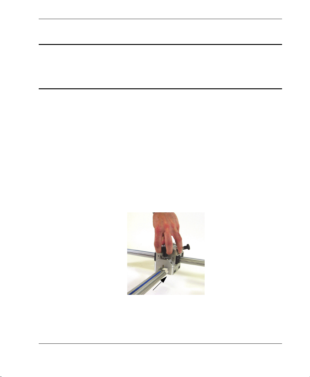
To insert the Y-axis into the X-axis module
1. Pull up on the Y-axis quick release device (see Figure 2-1 on page 17).
2. Slide the Y-axis into the X-axis module.
Figure 2‑1 Inserting the Y‑axis into the X‑axis module
3. Release the quick-release device.
Scanner Assembly and Setup 17
DMTA029-01EN, Rev. E, December 2017
2.2 Part Replacement and Adjustment
This section contains procedures for replacing or adjusting the bearing arm springs,
the mounting pods, the probe or transducer holders, and the encoders.
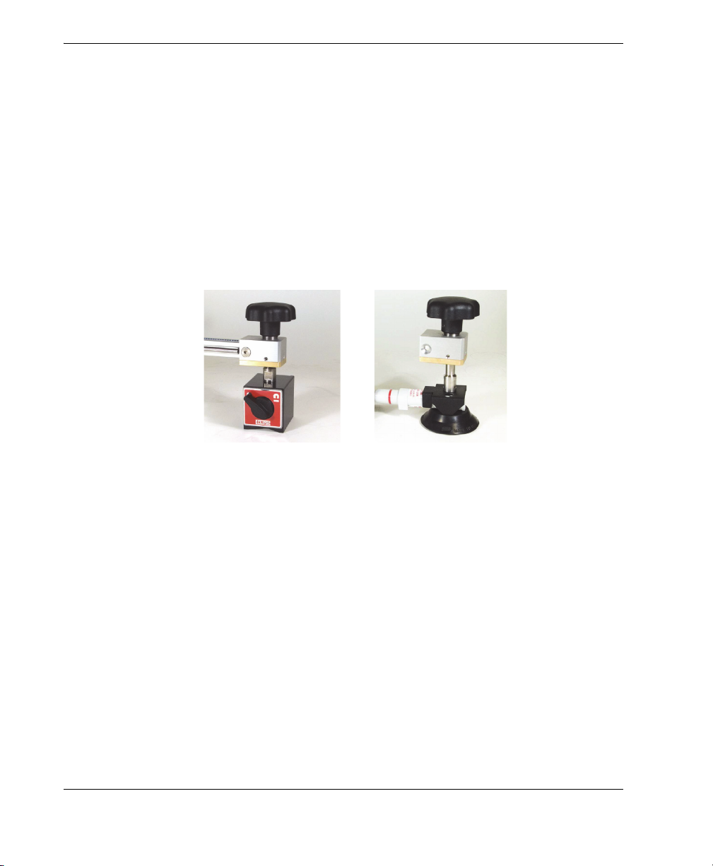
2.2.1 Replacing a Mounting Pod
The following procedure is valid for both the manual suction-cup model and the
magnetic-pod model (see Figure 2-2 on page 18). For details on mounting pods used
with an optional vacuum generator, see “Installing a Vacuum Generator with Pods”
on page 19.
Figure 2‑2 Mounting pod models: optional magnetic (left) and manual suction
cup (right)
To replace a mounting pod
1. Remove the screws at the locations shown in Figure 2-3 on page 19.
Chapter 218
 Loading...