

Page 1
PUS
GIF
,,,,XP
OES
GASTROINTESTINAL
WARNING
The user of this equipment should be thoroughly trained in the applicable
procedure. Furthermore, failure to read and thoroughly understand the
contents of this instruction manual may result in
patient and/or user. It is essential to follow the instructions contained
this and other manuals which pertain to any equipment and accessories
used in conjunction with the procedures. Possible injuries related to
endoscopic procedures may include perforation,
shock, hemorrhage, infection, explosion, etc.
Failure to follow these instructions may also result in damage to
malfunction of the instrument.
FIBERSCOPE
sefious injury to the
in
eleflrical burns and
andlor
Page 2
IMPOR
The Olympus GIF-XPIO has been designed for endoscopic diagnosis and treatment within the upper digestive
tract including esophagus, stomach and duodenum. Do not use the instrument for any purpose other than its
intended application.
Please read this entire manual carefully before using the instrument. It contains pertinent information on
the proper care and handling of your new fiberscope. Although fiberscopes by nature are delicate instruments,
proper handling and cleaning, as described in this manual, will greatly reduce the need for costly repair and
prolong the life of your new instrument.
This manual describes the recommended procedure for preparing and inspecting the equipment prior to use,
It does not describe how an actual procedure is to be performed in detail.
a beginner with endoscopic technique and the medical aspects of
should be used only by physicians who have received thorough previous training in the art of flexible endoscopy.
TANT
Nor does it attempt to acquaint
gastroenterologicaI endoscopy. This instrument
The safety and performance of an endoscopic system depends not only on the fiberscope but also on any ancil-
it
lary equipment used with it. To insure compatibility,
with this fiberscope.
lf you have any questions about the operation, safety or any of the material contained in this manual, please
con tact your Olympus representative or the nearest Olympus office.
is recommended that you use only Olympus accessories
Page 3
UPON RECEIVING THE EQUIPMENT
Hold
fiberscope
with
both
hands.
Please check each item in the set against the list of standard components found in Section
if there are any missing or defective parts. Refer to the following sections on
MAIN SPECIFICATIONS AND
3.
Contact Olympus
NOMENCLATURE to become acquainted with the name and function of each part of the instrument. Review
the instrument preparation, inspection and
cleaning/disinfecting procedures carefully. The fiberscope should be
disinfected prior to its initial use.
The fiberscope and accessories should be removed from the carrying case and stored asdescribed in Section
Storage.
The carrying case is not intended to be used for storage of the equipment. Retain the carrying case
6-4
only for shipping or transporting the instrument.
.P$
Remove the
ETO
cap (venting cap) from the fiberscope and store in an appropriate place.
PRIOR TO USE
In addition to thoroughly reading this manual, refer also to the instruction manuals supplied with your light
source, electrosurgical unit, accessories and other ancillary equipment.
CAUTION:
The GIF-XP10 is a precision instrument. Its design incorporates many features to insure patient safety.
cular, the angulation system is constructed to provide smooth response and maximal angulation of the distal tip
when normal force is applied to the angulation control knobs. Excessive pressure applied to the angulation
control knobs will result in damage to the fiberscope and may cause patient injury.
Before introducing the instrument into the patient be certain that the angulation control locks are in the "Free"
("F")
position and that the distal tip moves without resistance. If abnormal resistance is encountered when
introducing the instrument or when operating the angulation mechanism, DO NOT USE THE INSTRUMENT.
Contact your Olympus representative or the nearest Olympus office.
In parti-
Page 4
CONTENTS
1
.
FEATURES . MAIN SPECIFICATIONS
.........................
1
1-1
1-2
2
.
NOMENCLATURE
.
3
STANDARD SET
.
4
PREPARATION INSPECTION
4-1
4-2
4-3
4-4
4-5
4-6
5 .
OPERATING THE FIBERSCOPE
5-1
5-2
5-3
5-4
6-1
6-2
6-3
6-4
Features
Main Specifications
.............................................
.........................................
..........................................
.
Preparation of Fiberscope
Preparation and Inspection of Light Source
Preparation and Inspection of Suction Device
Preparation and Inspection of Biopsy Forceps
Inspection of the Fiberscope
Inspection of the Endoscopic System
Preparation for Use
l nsertion and Observation
Biopsy
Withdrawing the Fiberscope
Cleaning. Disinfection. Sterilization
Cautions
Cleaning. Disinfection and Sterilization Procedures
Storage
..............................................
............................................
............................................
1
.....................................
................................
.................................
.....................
...................
...................
...............................
.........................
.............................
.....................................
.................................
...............................
..........................
................
1
2
4
5
5
5
6
6
7
8
10
10
11
13
13
14
15
17
26
8 .
ENDOSCOPIC PHOTODOCUMENTATION
8-1
8-2
8-3
9
.
TROUBLESHOOTING GUIDE
.
10
ENDOSCOPIC SYSTEM CHART
Still Photography
CCTV
Cinematography
..............................................
......................
......................................
........................................
................................
.............................
28
28
29
30
31
34
Page 5
I
FEATURESeMAIN SPECIFICATIONS
I-1
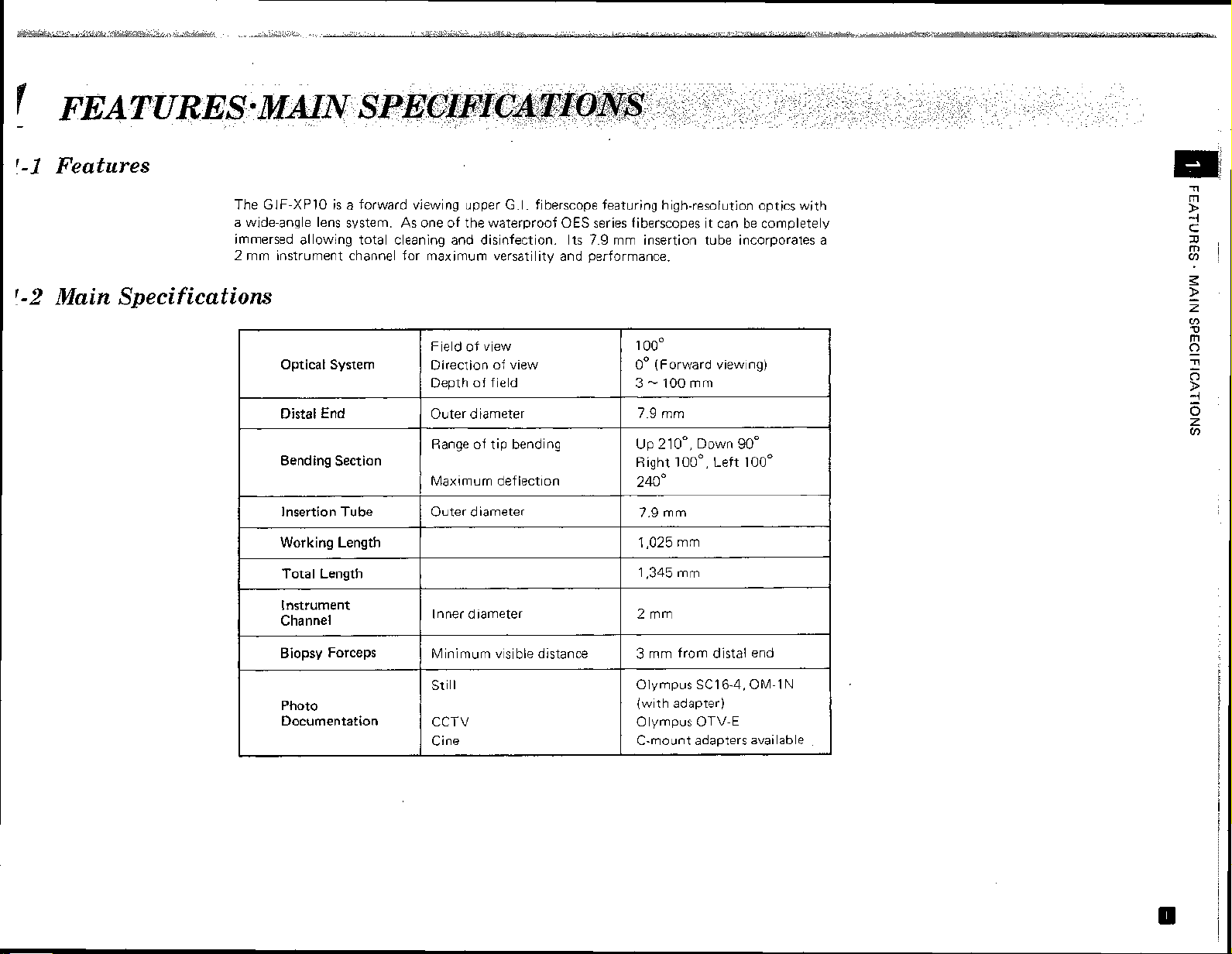
Features
The
1-2
Main Specifications
GIF-XP10
a wide-angle lens system. As one of the waterproof OES series fiberscopes it can be completely
immersed allowing total cleaning and disinfection.
2
mm instrument channel for maximum versatility and performance.
is a forward viewing upper G.I. fiberscope featuring high-resolution optics with
mm insertion tube incorporates a
Its 7.9
Optical System
Distal End
Bending Section
Insertion Tube
Working Length
Total Length
l nstrument
Channel
Biopsy Forceps
Photo
Documentation
Field of view
Direction of view
Depth of field
Outer diameter 7.9 mm
Range of tip bending Up 21
Maximum deflection
Outer diameter 7.9 mm
Inner diameter
Minimum visible distance
Still
CCTV Olympus OTV-E
Cine C-mount adapters available
1
00°
0"
(Forward viewing)
3
-
100
mm
oO,
Down
90'
Right
loo0,
Left
100'
240'
1,025
mm
1,345 mm
2
mm
3
mm from distal end
Olympus SC16-4, OM-I
(with adapter)
N
Page 6
&
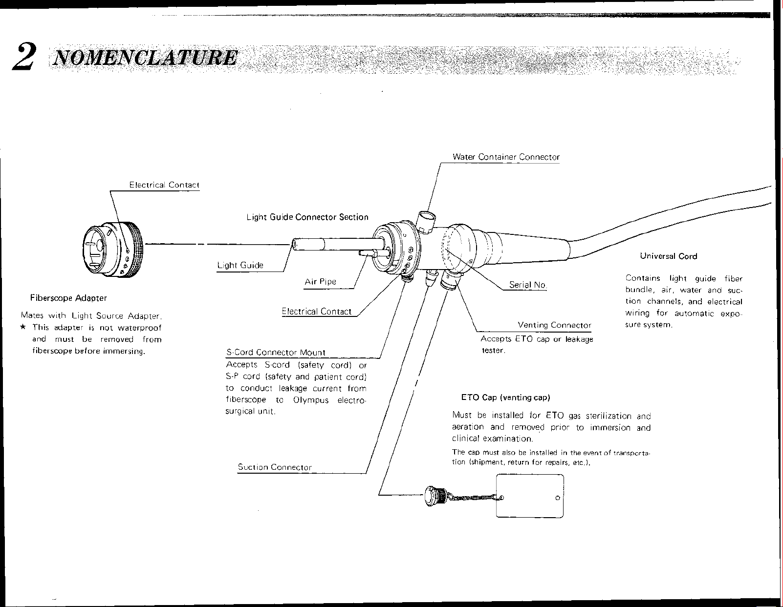
NOMENCLATURE
Water Container Connector
7
Electrical Contact
7
Fiberscope
Mates
*
This
and must be removed from
fiberscope before immersing.
Adapter
w~th Light Source Adapter
adapter
is
not waterproof
Light Guide Connector Section
Electrical Contact
S-Cord Connector Mount
Accepts S-cord (safety cord) or
S-P
cord (safety and patient cord)
to conduct leakage current from
fiberscope to
surgical unit.
Suction Connector
Olyrnpus electro-
/
!/
------/
/ /
/
\
Accepts
tester.
€TO
Cap
Must be installed for ETO gas sterilization and
aeration and removed prior to immersion and
clinical examination.
The cap must also be installed in the event
tion (shipment, return
Venting Connector
ETO
cap or leakage
(venting cap)
for
repairs, etc.).
of
\
Universal Cord
Contains light guide fiber
bundle, air, water and suction channels, and electrical
wiring for automatic exposure system
transporta-
Page 7
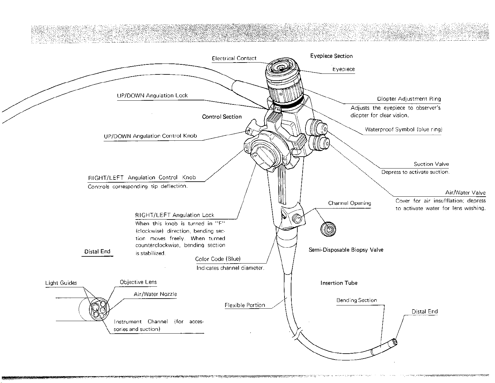
UPIDOWN Angulatio
Controls corresponding tip deflection.
Control Section
Eyepiece Section
Eyepiece
8
Diopter Adjustment Ring
Adjusts the eyepiece to observer's
diopter for clear vision.
Cover for air insufflation; depress
to activate water for lens washing.
When this knob is turned in
(clockwise) direction, bending sec-
tion moves freely. When turned
counterclockwise, bending section
Distal End
Light Guides Objective Lens
h
Instrument Channel (for acces-
\
sories and suction)
is stabilized.
"F"
Color Code (Blue)
Indicates channel diameter.
'
\
/
rl
Semi-Disposable Biopsy Valve
Insertion Tube
Page 8
3
O
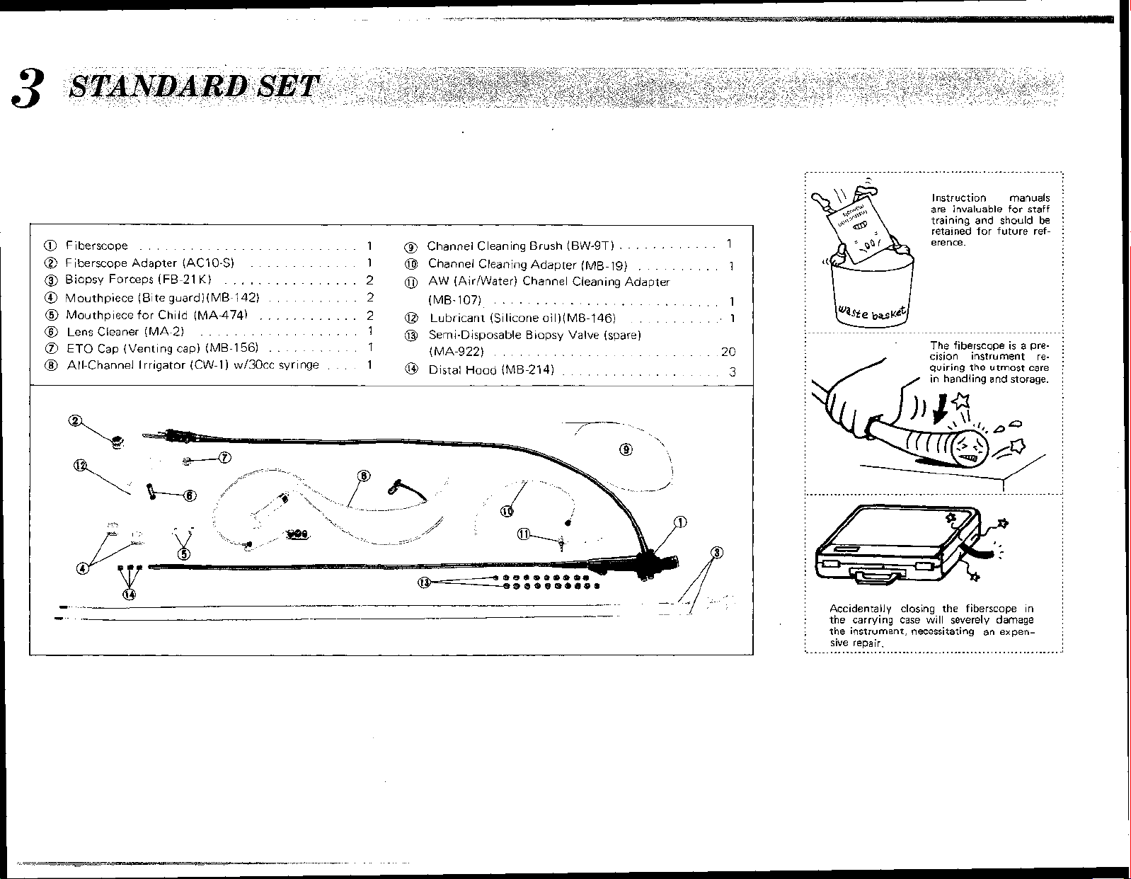
STANDARDSET
Fiberscope
@
Fiberscope Adapter (AC10-S)
@
Biopsy Forceps (FB-21
@
Mouthpiece (Bite guard) (MB-142)
@
Mouthpiece for Child (MA-474)
@
Lens Cleaner (MA-2)
a
ETO
@
All-Channel Irrigator (CW-1) wl30cc syringe
..........................
............
K)
................
............
..................
Cap (Venting cap) (ME-1
56)
..........
...........
...
1
@
Channel Cleaning Brush (BW-ST) 1
1
@
Channel Cleaning Adapter (MB-19)
2
0
AW (Air/Water) Channel Cleaning Adapter
2
2
1
1 (MA-922)
1
(MB-107)
@
Lubricant (Silicone oil)(MB-146)
@
Semi-Disposable Biopsy Valve (spare)
@
Distal ~~~d (MB-214)
............
..........
...........................
............
.........................
...................
1
1
1
.20
3
,*"aL*
';,,,.,\+'
I
Accidentally closing the fiberscope in
the carrying case
j
:
the instrument, necessitating an expen-
j
sive repair.
m
.............................................................
Instruction manuals
are invaluable for staff
training and should be
retained for future reference.
'
The fiberscope is a precision instrument requiring the utmost care
in handling and storage.
will
severely damage
Page 9
4-1
Preparation of Fiberscope
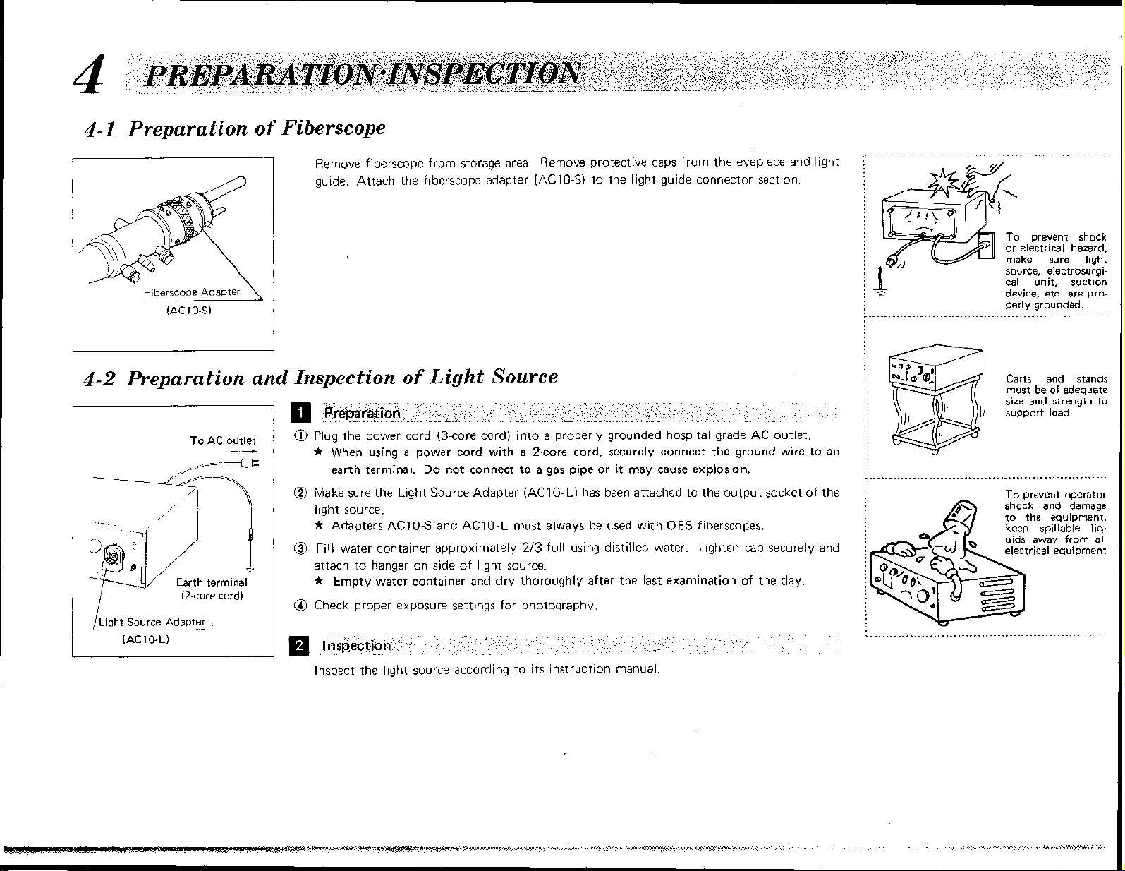
Remove fiberscope from storage area. Remove protective caps from the eyepiece and light
guide. Attach the fiberscope adapter
(AC10-S) to the light guide connector section.
n
To prevent shock
or electrical hazard,
make sure light
source, electrosurgical unit, suction
device, etc. are properly grounded.
4-2
Preparation and Inspection of Light Source
r
I
/Liclht Source Adapter
L
To AC outlet
__C
//====-EL=
Earth term~nal
(2-core cord)
-
Preparation
a
Plug the power cord (3-core cord) into a properly grounded hospital grade AC outlet.
t
When using a power cord with a 2-core cord, securely connect the ground wire to an
earth terminal. Do not connect to a gas pipe or it may cause explosion.
@
Make sure the Light Source Adapter (AC10-L) has been attached to the output socket of the
light source.
.r$
Adapters
@
Fill water container approximately 213 full using distilled water. Tighten cap securely and
attach to hanger on side of light source.
+
Empty water container and dry thoroughly after the last examination of the day.
Check proper exposure settings for photography
!
inspection
Inspect the light source according to its instruction manual.
AC10-S
and
AC10-L
must always be used with
OES
fiberscopes.
Carts and stands
must be of adequate
size and strength to
support load.
To prevent operator
shock and damage
he equipment,
Page 10

4-3
Preparation and Inspection of Suction Device
@
Connect the power cord of suction device to the
-
earth terminal
The suction device must be in safe and proper working condition.
@
lnspect the suction device following its operating manual.
@
Connect the suction tube to the suction device and to the suction connector on the light
guide section of the fiberscope.
@
Turn on suction device. Suction is controlled by the fiberscope's suction valve.
see page
5)
following its operating manual.
AZ
mains (and the ground wire to the
4-4
I
Preparation and Inspection of Biopsy Forceps
l
nspecting forceps operation
Open
-
-
Close
I)
Preparation
Select proper biopsy forceps for fiberscope being used. (Refer to the System Chart, page
*
Always have spare forceps available.
Inspection
Biopsy forceps should be inspected before each use
@
Form a loop in the biopsy forceps approximately 20cm in. diameter. Make sure that the
forceps cups open and close smoothly when the handle is lightly operated.
@
Inspect snares, etc., following individual instruction manuals.
@
If there
etc., the item should be replaced with a new one.
8
*
is
any irregularity in the operation or external appearance of a forceps, snare,
Replace bent or kinked accessories.
All Olympus accessories have been designed and manufactured with utmost care. Due
to the delicate nature of the
safe nor economical to repair endoscopic accessories. In the interest of patient safety,
policy
is
Olympus'
individuals should not be attempted.
to replace rather than repair these items. Repair by unauthorized
small precision parts involved,
!
it
is
considered neither
35.)
Any accessory which
its
along
will be difficult to pass through the
fiberscope, and must be replaced.
.............................................................
shaft will not operate smoothly,
is
kinked or bent
Page 11
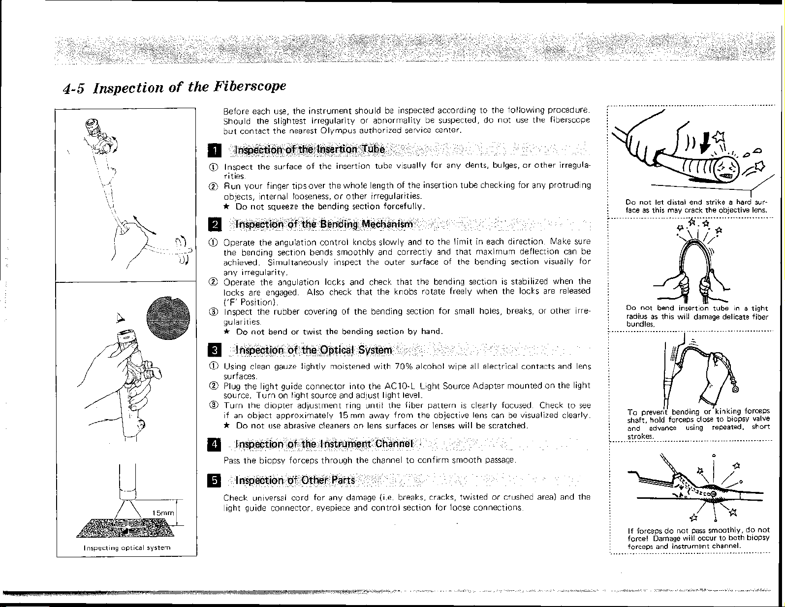
4-5
Inspection
of
the Fiberscope
Before each use, the instrument should be inspected according to the following procedure.
Should the slightest irregularity or abnormality be suspected, do not use the fibersco~e
but contact the nearest Olympus authorized service center.
El
@
Inspect the surface of the insertion tube visually for any dents, bulges, or other irregula-
rities.
@
Run your finger tips over the whole length of the insertion tube checking for any protruding
objects, internal looseness, or other irregularities.
@
Operate the angulation control knobs slowly and to the limit in each direction. Make sure
the bending section bends smoothly and correctly and that maximum deflection can be
achieved. Simultaneously
any irregularity.
@
Operate the angulation locks and
locks are engaged.
('F'
@
Position).
Inspect the rubber covering of the bending section for small holes, breaks, or other irregularities.
a$
Do not bend or twist the bending section by hand.
a
@
Using clean gauze lightly moistened with
surfaces.
@
Plug the light guide connector into the AC10-L Light Source Adapter mounted on the light
source. Turn on light source and adjust light level.
@
Turn the diopter adjustment ring until the fiber pattern
if an object approximately 15mm away from the objective lens can be visualized clearly.
-&
Do not use abrasive cleaners on lens surfaces or lenses will be scratched.
Inspection
p
Pass the biopsy forceps through the channel to confirm smooth passage.
inspect the outer surface of the bending section visually for
check that the bending section is stabilized when the
Also check that the knobs rotate freely when the locks are released
70%
alcohol wipe all electrical contacts and lens
is
clearly focused. Check to see
of
the Instrument Channel
...........................................................
j
:
j
Do not let distal end strike a hard sur-
j
face as this may crack the objective lens.
;
.
............................*...*.......................
9;
;
.a
:
bundles.
...........................................................
:
and advance using repeated, short
stroltes.
...........................................................
I
I
Inspecting optical system
Check universal cord for any damage (i.e. breaks, cracks, twisted or crushed area) and the
light guide connector, eyepiece and control section for loose connections
i
If
forceps do not pass smoothly, do not
I
1
force! Damage will occur to both biopsy
I
forceps and instrument channel.
..........................................................
Page 12
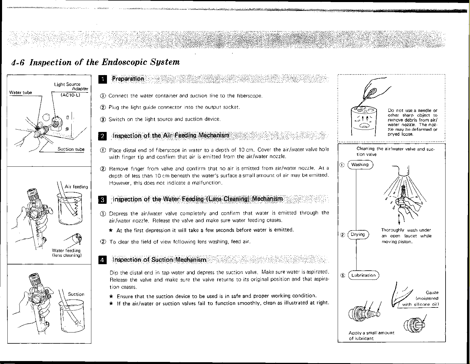
4-6
water tuh
Inspection
-7
~iant Source
,
Air feeding
9
Water feedincr
(lens cleanins)
of
the Endoscopic System
Preparation
a
Connect the water container and suction line to the fiberscope.
@
Plug the light guide connector into the output socket.
@
Switch on the light source and suction device.
lnspection of the Air Feeding Mechanism
a
Place distal end of fiberscope in water to a depth of
with finger tip and confirm that air is emitted from the airlwater nozzle.
@
Remove finger from valve and confirm that no air is emitted from airlwater nozzle. At a
depth of less than
However, this does not indicate a malfunction.
lnspection of the Water Feeding (Lens Cleaning) Mechanism
a
Depress the airlwater valve completely and confirm that water
airlwater nozzle. Release the valve and make sure water feeding ceases.
-i$
At the first depression it will take a few seconds before water is emitted.
@
To clear the field of view following lens washing, feed air
lnspection of Suction Mechanism
10
10
cm. Cover the airlwater valve hole
cm beneath the water's surface a small amount of air may be emitted.
is
emitted through the
................................................................
L-
Do not use-a needle or
other sharp object to
remove debris from
water nozzle. The noz-
rnav
1
...............................................................
Cleaning the airlwater valve
tion valve
Washing
I
zle
pryed ioose.
be deformed or
r
Thoroughly
an
open faucet while
moving piston.
wash
and
under
air/
suc-
L
Dip the distal end in tap water and depress the suction valve. Make sure water is aspirated.
Release the valve and make sure the valve returns to its original position and that aspira-
tion ceases.
.f$
Ensure that the suction device to be used
4
if
the airlwater or suction valves fail to function smoothly, clean as illustrated
is
in safe and proper working condition.
at
right.
@
(Lubrication)
Apply a small amount
of lubricant
Page 13
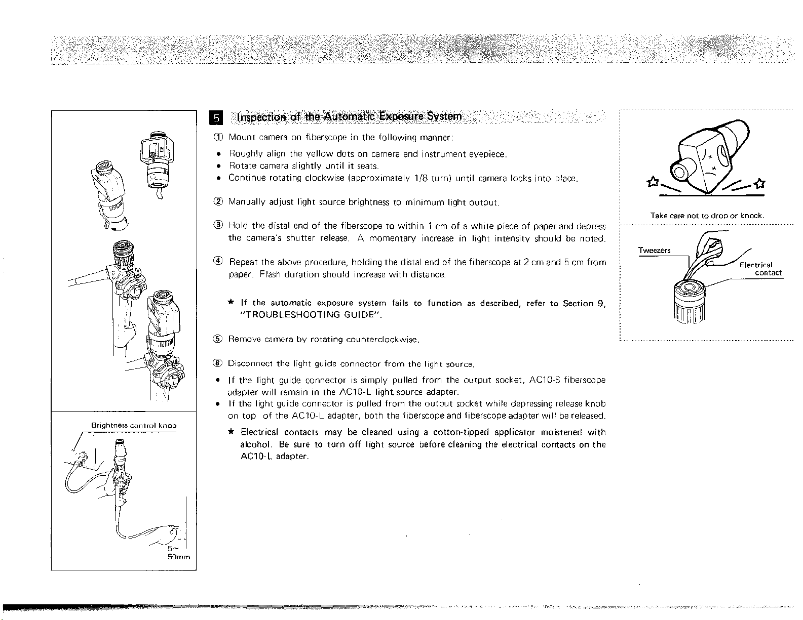
Brightness control knob
Inspection of the Automatic Exposure
@
Mount camera on fiberscope in the following manner:
o
Roughly align the yellow dots on camera and instrument eyepiece.
Rotate camera slightly until it seats.
Continue rotating clockwise (approximately
@
Manually adjust light source brightness to minimum light output
@
Hold the distal end of the fiberscope to within 1 cm of a white piece of paper and depress
the camera's shutter release. A momentary increase in light intensity should be noted.
@
Repeat the above procedure, holding the distal end of the fiberscope at 2 cm and 5 cm from
paper. Flash duration should increase with distance.
*
If the automatic exposure system fails to function as described, refer to Section
"TROUBLESHOOTING GUIDE".
@
Remove camera by rotating counterclockwise.
@
Disconnect the light guide connector from the light source.
s
If the light guide connector is simply pulled from the output socket, AC10-S fiberscope
adapter will remain in the
If the light guide connector is pulled from the output socket while depressing release knob
on top of the
Ibp
Electrical contacts may be cleaned using a cotton-tipped applicator moistened with
alcohol. Be sure to turn off light source before cleaning the electrical contacts on the
AC10-L
AC10-L adapter, both the fiberscope and fiberscope adapter will be released.
adapter.
AC10-L light source adapter.
System
118
turn) until camera locks into place.
.............................................................
Take care not to drop or knock.
9,
Page 14

5
OPERATING THE FIBERSCOPE
5-
P
Preparation for
r-P,-.
yi
17''
This section describes the basic operation
The endoscopist should carefully evaluate the clinical factors involved and decide on the technical details of the procedure.
To become more thoroughly acquainted with some of the potential hazards associated with flexible endoscopy,
the following are examples of possible complications resulting from improper technique.
Improper Technique
1.
Use of faulty fiberscope and/or accessory
2.
Forceful insertion without clear view of the lumen
3. Prolonged suction with distal tip in contact with
rnucosal surface
Prolonged close-up observation with intense illumination
Overinstifflation
Retroflexion of the fiberscope within the esophagus
or duodenal bulb
Blind or abrupt protrusion of accessory from distal tip
Electrosurgery without clear view
Withdrawal of fiberscope
locked position
Blind withdraw1 of fiberscope
Improperly
cleaned/disinfected instruments
wit,h angulation controls in
of
th; fiberscope and outlines a general procedure for endoscopy.
SPElClAL
NOTE
Possible Complication
Mucosal trauma, Perforation, Laceration,
Electrical shock, etc.
Perforation, etc.
Bleeding, Suction artifact, etc.
Thermal injury to mucosa, etc.
Pain, Rupture, etc.
Instrument impacted and cannot be withdrawn
Perforation, etc.
Mucosal burns, Perforation, etc.
Trauma, Perforation, Laceration, etc
Trauma, Perforation, Laceration, etc.
Cross-contamination, Infection, etc.
Use
'
0
Disinfection/Sterilization
Disinfect or sterilize the fiberscope and accessories as described in Section
I
1
Application
c,
Wipe moisture from objective lens.
a
Apply lens cleaner to a piece of clean gauze and lightly wipe the objective lens. Remove
af
Lens Cleaner (Anti-Fogging Agent)
of Instruments
6.
Do not occlude airfwater
nozzle when applying lens
cleaner.
\
?s4noeo
c'Iqe
t
When cleaning the objective lens, always wipe in a direction away from the airlwater
nozzle.
I
Attaching the Distal Hood
a
Attach the distal hood, with rounded edge facing outward, while holding the distal end of
the fiberscope firmly between finger tips. Gently press on hood.
To remove, hold the distal end of the fiberscope firmly.
the hood and gently pull off.
ft
To prevent accidental dislodgement of the hood, make sure mating surfaces of the hood
and distal end are clean and dry before attaching.
*
lf hood appears cracked or worn, do not use.
(if
required)
Using finger tips, grasp the edge of
Replace with a new one.
i
To prevent damage to bending section,
I
grasp insertion tube near the distal
j
when installing hood.
end
Page 15

Diopter Adjustment
Turn the diopter adjustment ring until the fiber pattern is clearly focused
*
Four color-coded index lines serve as a reference for repeated setting.
5-2
I
I
Insertion and Observation
Preparation for Insertion
$TI
Always use a mouthpiece (bite guard) to prevent the instrument from being bitten.
@
Lubricate the insertion tube wi.th a water soluble medical grade lubricant, taking care to
avoid the distal tip.
Holding the Fiberscope
The control section of the instrument is designed to be held in the left hand. The airlwater
and suction valves are activated by the index finger. The upldown angulation control knob
is operated by the thumb. The right hand is free to manipulate the insertion tube and the
ii
I I
'I
Mouthoiece
I
1
1
'
left/right angulation control knob.
Adjusting Brightness
Adjust the brightness control knob on the light source to a comfortable level of illumination.
*
Always use the minimum necessary light level to avoid thermal mucosal damage as well
to protect your eye.
Tip Deflection
Operate the angulation control knobs as necessary to guide the distal end for insertion and
observation.
t
If
the angle control mechanism ceases to function, or if any other irregularity is noticed
in the operation of the fiberscope, stop the examination immediately; free the angulation
locks and return the angulation control knobs to their neutral position. Carefully with-
draw the fiberscope while observing through
*
Always operate the angulation conrrol knobs slowly.
it.
as
Petroleum based lubricants will cause
stretching and deterioration of bending
section rubber.
Always use a mouthpiece to prevent
damage to the insertion tube.
Page 16

I
- - -
-_ - _
e4
!-
d
1.
_ . _ _
-
-
1
Aspiration
Fluid or foreign matter obscuring the visual field may be aspirated by depressing the suction
valve. Aspiration is also useful for removing excess air.
Cleaning the Objective Lens
@
Secretions and foreign matter adhering to the objective lens may be removed by simultane-
ously depressing the airiwater and suction valves.
(2'
Water drops remaining on the lens may be removed by feeding air.
1
I
,/'
Operating
airiwater
2%-
-
.
suction
and
valves as necessarv.
-yx,
Ilioprer
.
aai
.srmrnr
I
2
@
1
I
Adjusting Lumen lnsufflation
Maintain the proper level of lumen insufflation for observation by feeding and aspirating air
*
Overinsufflation
may
cause excessive patient discomfort and possible injury.
Using the Lecturescope (Teaching Attachment)
Either the LS-10 lecturescope or LS-2 lecturescope (with A10-L2 adapter) may be used with
the fiberscope
If des~red a camera may be attached to the prrmary eyeplece of the LS-10 lecturescope.
THERE IS A RISK OF THERMAL INJURY TO TISSUE FROM PROLONGED EXPOSURE TO THE INTENSE ILLUMINATION TRANSMITTED THROUGH
Because of the rncreased light carry lng capabillttes of OES endoscopes combrned wlth the
h~gh output of hrgh-rntensrty (Xenon) l~ght sources,
lrght energy and to concentrate this energy ~n a very small area (for example, when the
of
flberscope
result). Because
control, 'the level of
unless manually reduced
The risk of injury is increased under the following conditions:
1)
2)
3)
The following recommendations
1)
2)
To prevent
lamp on when not in use.
tip comes ~n close contact with the mucosa, thermal injury to the tlssue may
thls fiberscope does not contarn a photocell for automatic brightness,
~lluminatlon wlll become very great under close-viewing condrtions
Prolonged close contact or close stationary viewlng of the mucosa
Advanc~ng the flberscope through a narrow lumen (e g esophagus, pharynx, etc
Usrng a h~gh-rntensrty llght source (e g , CLV, CLX, CLX-F)
will
Use the minimum level of illumination necessary, for adequate v~sualiration. The
filter(BorC)built into
When possible, avoid close stationary viewing.
acc~dents, do not leave the flberscope plugged into the light source with the
high-intensity(Xenon)light
WARNlNG
it
IS
posstble to convey a large amount
reduce the rlsk of thermal Injury
sourcesmay be used for this purpose.
A
FIBERSCOPE
1
)
Page 17

INhen forceps cups
fail to close
5-4
Withdrawing the
Inserting Biopsy Forceps
a
While visualizing the area of interest, insert biopsy forceps into the instrument channel with
its cups closed.
4
If the forceps encounters resistance to passage through the bending section, decrease tip
angulation until smooth passage is possible. Application of a medical grade lubricant to
the forceps prior insertion into the fiberscope will enhance passage.
@
Slowly advance the forceps using repeated short strokes, grasping the forceps approximately
3
cm from the biopsy valve. When the tip protrudes approximately 3 mm from the distal
end, the forceps will come into view.
*
If the biopsy valve leaks fluid or air, replace with a new one.
Hold forceps
close to biops
valve and advance using
repeated shor
strokes.
Biopsy Procedure
Tissue samples are obtained by grasping the mucosa in the biopsy cups and then gently
pulling the forceps back until the specimen is removed.
*
Do not attempt to cut through the tissue by applying excessive force.
*
Withdraw forceps slowly with cups in a closed position
&
In the event the cups of forceps fail to close when the slider is operated making it impossible to withdraw the forceps, close the cups by winding proximal portion of the shaft
several times around your finger. If this fails to close the cups, withdraw the forceps as
as
possible
far
\
withdraw both fiberscope and forceps.
into channel opening. While viewing through the fiberscope, carefully
Fiberscope
If
resistance is encountered when passing
i
I
biopsy forceps. DO
:
tensive damage to both forceps and
j
fiberscope may result.
...........................................................
/
Advance forceps slowly.
jury or perforation, always view through
:
I
fiberscope when advancing forceps.
.........................................................
NOT
FORCE.
To prevent in-
Ex-
Before withdrawing the fiberscope, aspirate accumulated air and be sure that upldown and
rightheft angulation locks are in the "Free"
@
Always view through the fiberscope when withdrawing the instrument.
ft
The fiberscope must be cleaned immediately after withdrawal from the patient. (Refer
to
pp.
19-21.)
(F)
position.
!
Do not apply excessive force when
j
opening and closing biopsy forceps.
L......
Page 18

6
6
MAINTENANCE
6-1
Cleaning, Disinfection, Sterilization
Endoscopic instruments must be meticulously cleaned prior to disinfection or sterilization. The methods employed to achieve these conditions are left to the discretion of the endoscopist, hospital infection control
committee, etc.
Olympus instruments are made of materials and constructed in a manner which may not tolerate certain
methods of cleaning, disinfection or sterilization. Those procedures, as described on pages
manual, have been thoroughly tested and found to have no adverse effects. Strict adherence to these procedures is highly recommended.
17 - 25
of this
%
Only those fiberscopes identified by a Blue Ring on
'88
Only those accessories identified by a Green Color or marked "AUTOCLAVE" may be autoclaved.
the
Eyepiece may be totally immersed.
'
Non-OES fiberscopes
'..._____.....___.......--................................~......,
Page 19

6-2
Cautions
General Precaution
e
Before using any disinfectant solution not mentioned below, check with Olympus.
c
Removable parts (e.g. distal hood, biopsy valve, airlwater and suction valves), as well as the areas on which
these parts are mounted, should be thoroughly cleaned and disinfected (sterilized).
P,
The water container should be emptied, cleaned, and disinfected at the end of each day's procedures.
Disinfectant Solution
Reference herein to solutions for disinfection is not an endorsement of their germicidal effectiveness. Oual-
c
ified persons from the disinfectant manufacturer should be consulted if any questions exist on this subject.
e
When the disinfectant solution has been in contact with the instrument for the recommended time, remove the
instrument from the disinfectant and rinse thoroughly to remove all toxic residue and to prevent instrument
deterioration. The recommended dilution percentage and contact time listed below should not be exceeded.
c
Rubber gloves should be worn for protection against skin irritation, infection, etc
Disinfectant
Solution
MATERIAL
Alcohol
(Disinfectant
Ethanol)
Surgical scrub
soap solution
lodophor
Glutaraldehyde
70%
BRAND NAME
Wescodyne
Cidex (2%)
Sonacide (2%)
Glutarex (2%)
(
I
.6%)
Sporicidin
Alhydex Plus
(2.2%)
Aldehyde 28
(2%)
DISTRIBUTED BY
West Chemical Products
(USA)
Surgikos (USA)
Ayerst Labs (USA)
3-M Medical Products
Sporicidin Co. (USA)
Surgikos (West Europe)
Antiseptics Consultant
Service (Australia)'
CONDITIONS
Wipe using alcohol dampened gauze
I
Maximum
Dilution:
Max. Immersion: 20 Min.
Follow Manufacturer's Instructions
mmersion: 30 Minutes
100X (0.016%)
-
Page 20

Ethylene
Prior to sterilizing the f iberscope, the ETO Cap (venting cap) must be attached. 0 ES fiberscopes are completely sealed to rnake them watertight.
scope from escaping as a vacuum is created within the sterilization chamber. This will cause the rubber cover-
ing the bending section to rupture. After the ETO procedure is completed, the
order to reseal the fiberscope and insure watertightness.
e
Before sterilization, the instrument must be thoroughly cleaned and dried as described in pages 19 - 21 of
the manual. Failure to do
The instrument must be properly aerated after ETO sterilization to remove all residual toxic gas.
@
Always use a biological indicator and follow the manufacturer's instructions for the particular gas sterilizer
being used.
Oxide
Gas Sterilization
Failure to attach the ETO cap will prevent the air sealed inside the
so will inhibit sterilization.
ETO
Cap must be removed in
fiber-
Formalin
Anprolene
Gas
Ethylene Oxide
Gas
Gas sterilizer
gas
H.W. Andersen Products
I
To
be kept in sealed condition for 24
hours max.
Follow Manufaturer's Instructions
Temperature 55°C (131°F)
Pressure 1 .7kg/cm2
Humidity 50%
Gas Concentration 10%
Time 4 Hours
Aeration Time: 7 days at room temperature or
chamber between
57°C
I2 hours in an aeration
50"~ (122"~) and
(135°F)
Autoclave
@
Only those accessories identified by a Green Color or marked "AUTOCLAVE" may be autoclaved.
B)
Meticulous mechanical cleaning followed by 5 minutes of ultrasonic cleaning (at
datory prior to autoclaving. (Refer to Autoclavable Accessory Instruction Manual for details.)
@
Standard autoclave cycles, including "flash" may be used provided the temperature does not exceed 132OC.
I I
Heat
Boiling Water
Autoclave
(
Maximum Immersion: 30 Minutes
2 atmospheres of air pressure
for 5 minutes or 1 atmosphere (121"~ or
250°F) for 20 minutes
40
kHz or higher) is man-
(132°C or 270"~)
(24 psi)
I
Page 21

6-3
Cleaning, Disinfection and Sterilization Procedures
Supplies
Needed
Cleaning solution Disinfectant solution Large basin for water
Semi-disposable
biopsy valve
(MA-922)
Rubber gloves
ETO
cap (venting cap)
(MB-156)
Large basin for disinfectant
solution
All-channel irrigator (CW-1)
30cc syringe
with
j
o
To avoid extensive damage and costly
repair,
it
:
fiberscopes be tested for water leakage
i
prior to immersion in cleaning solutions.
j
@
To facilitate leak testing and cleaning procedures, the use of a leakage
tester, maintenance unit
i
endoscope washer
mended (optional items).
Refer to the operating manuals provided
with these units.
L..................
is recommended that
(EW-10)
............................................
OES
(MU-1 ) or
is- recorn-
Scrub brush (soft)
Gauze pads
A~rlwater channel cleaning adapter
(MB-I 07)
Channel cleaning brush
(BW-ST)
Channel cleaning adapter
(MB-19)
Leakage Tester (optional)
Page 22

LEAN IMMEDIATELY AFTER PROCEDURE
1. Wipe insertion tube with gauze.
2.
Turn off air pump. Remove AIRIWATER VALVE by slowly pulling out and place in cleaning solution.
3.
Insert AIRIWATER CHANNEL CLEANING ADAPTER (blue collar). Turn on air DumD.
4.
Alternately feed water and air for 10 seconds each. Turn off light source.
5.
Place distal tip in water and suction for approximately 10 seconds. Then alternate suctioning of water and air several times. Turn off
suction device.
6.
Remove AIRWATER CHANNEL CLEANING ADAPTER, SUCTION VALVE and BIOPSY VALVE. Place in cleaning solution.
7.
PERFORM LEAK TEST PROCEDURE.
8.
Immerse insertion tube in cleaning solution.
9.
Insert channel cleaning brush through insertion tube, universal cord and channel opening to brush the entire suction line.
10. Turn off suction device and remove suction line and channel cleaning adapter.
11. Immerse entire instrument in cleaning solution. Scrub all external surfaces.
12. Using a soft brush, gently wash and rinse all valves.
13. Install AW CHANNEL CLEANING ADAPTER and SUCTION
14. Connect suction tube to suction connector on the instrument. While holding the control section out of water, turn on suction device,
making certain free end of the channel cleaning adapter remains in water. Aspirate water for approximately 10 seconds.
15. Remove entire instrument from water. Continue to aspirate air for approximately
suction line.
16. Dry all external surfaces of the instrument.
17.
Turn off light source.
VALVE, and attach CHANNEL CLEANING ADAPTER.
,
.
Remove instrument, place in clean water and rinse.
30
seconds. Turn off suction device, and disconnect
1. Connect All-Channel lrrigator (CW-1
2. Immerse fiberscope and All-Channel
3.
Pump disinfectant solution through all channels. Gas Sterilization Cycle
4.
Disconnect All-Channel lrrigator (CW-1) and allow Instrument to
remaln in disinfectant solution for Recommended Period of Time.
5.
Following disinfection, remove the Instrument from dis~nfectant
solution and place in clean water.
6. Reattach All-Channel Irrigator. Place weighted end of blue intake
tube in water. 2. Remove ETO Cap.
7.
Flush all channels with clean water until thoroughly rlnsed.
Remove weighted end of blue intake tube from water and repeat and BIOPSY VALVE which have been sterilized
flushing process, forcing air through channels to expel water.
Rinse the outslde of the fiberscope under a running faucet. Remove All-
8.
Channel lrrigator from the fiberscope while rinsing.
9.
Plug
LG
until moisture has been expelled and channels are dry,
10.
Wipe dry outside surface of the Instrument
connector into light source and force air through all channels
DISINFECTION COMPLETED
)
to fiberscope
lrrlgator into dis~nfectant solut~on.
I
i
1
Aeration
3.
Install AIRIWATER VALVE, SUCTION VALVE
and dried.
II
STERl LlZATlON COMPLETED
Page 23

Detach airlwater valve and attach
AW
channel cleaning adapter.
Cleaning/Disinfecting/Sterilizing
the
Fi
berscope
CLEAN IMMEDIATELY AFTER PROCEDURE
Initiate the following cleaning procedure immediately after each examination. Failure
to do so may result in a malfunction of the instrument.
4
The light guide plug (chrome shaft extending from the light guide connector) may
be extremely hot immediately after removal from the light source.
DO NOT TOUCH!
Wipe insertion tube with gauze.
1.
+
Do not squeeze the bending section forcefully.
2.
Turn off air pump.
Remove
Insert AIR/WATER CHANNEL CLEANING ADAPTER (blue collar).
3.
Turn on air pump.
Alternately feed water and air for
4.
Turn off light source.
4
Place distal tip in water and suction for approximately
5.
tioning of water and air several times.
Turn off suction device.
*
6.
Remove AIR/WATER CHANNEL CLEANING ADAPTER, SUCTION VAVLE and
BIOPSY VALVE.
Place in cleaning solution.
AIR/WATER VALVE
The AirIWater Channel Cleaning Adapter will feed water through both the air channel
and water channel when depressed. It feeds air through both channels automafically
when the valve
Altern'ately insert and.remove distal end of the instrument.
is
released.
by
slowly pulling out and place in cleaning solution.
10
seconds each.
10
seconds. Then alternate suc-
Clean fiberscope immediately after each
j
j
examination.
........................................................
-....
j
AW
channel cleaning
/
adapter (blue collar)
use
in
Never
i
examination.
Remove fiberscope adapter before clean-
j
j
ingldisinfecting procedure.
L_______
.....................................................
clinica;&
(not waterproof)
Alternately feed
water and air.
Page 24

leakage
tester
Disconnect from light
source
r
wait
first
30
seconds.
and
\
connector
7.
Perform Leak Test Procedure.
@
Remove fiberscope from light source by simply pulling outward.
*
DO NOT DEPRESS Silver Button on top of the light source adpater (ACI
a
Be sure fiberscope adapter (AC10-S) remains in the light source adapter.
@
Detach water container and suction line from the light guide connector.
@
Insert black end of the leakage tester into output socket on the light source.
@
Turn on the light source.
t
Be sure air pump
tester, lightly depress the pin inside the connector cap.
@
Attach leakage tester to venting connector on the light guide connector.
*
Place the connector cap over the venting connector, aligning the pin on the connectoor
with the keywav on the cap. Depress and rotate cap clockwise (approximately
until no further .rotation is possible.
*
At this point, note expansion of the rubber covering of the bending section due to
increased internal pressure.
@
Immerse entire instrument in water.
Observe the instrument carefully for about
If no bubbling is observed from the instrument, the instrument is watertight. Proceed
to Step
If continuous bubbling is observed from a given area, this indicates a leak. Remove the
a
instrument from water immediately.
a
Turn off light source and disconnect leakage tester from light source.
Wait approximately
to its normal shape); then disconnect opposite end of leakage tester from the instrument.
DO NOT USE THE INSTRUMENT! Reattach all valves and distal hood (if used) and
send
,
@
Remove the entire instrument from the water and turn off the light source
Disconnect the leakage tester from the light source.,
e
Wait approximately
returns to its normal shape).
r
Disconnect the leakage tester from the venting connector on the light guide connector
by depressing and rotating counterclockwise.
*
-k
Immerse insertion tube in cleaning solution
8.
O.
Some initial bubbles may be observed due to air trapped in crevices on the fiberscope's outer surface. This is normal.
to
vour nearest Olvm~us Service Center.
Do not detach the leakage tester before the fiberscope has been removed from water.
When detaching the leakage tester, always disconnect from the light source first.
Failure to follow this exact procedure will not allow the instrument to depressurize
and damage will result.
Thoroughly dry the leakage tester.
is
also
"ON".
30
seconds (or until rubber which covers the bending section returns
30
seconds (or until the rubber which covers the bending section
To ensure that air is being emitted from the leakage
30
seconds.
0-L).
90
j
If
continuous bubbling
a
)
given area,
I
.................................................................
this
is
observed from
indicates a leak.
I
Page 25

Brushing the suction line
cleaning
Insert channel cleaning brush through insertion tube, universal cord and channel opening
9,
to brush the entire suction line.
5
Pass channel cleaning brush through suction valve housing at an angle of approximately 45'
until the brush extends from the distal end of the instrument. Brush channel several times.
Pazs the channel cleaning brush directly into the suction valve housing (approximately
90
)
brushing the entire length of the universal cord until the brush extends from the
su,ction connector. Brush several times.
Insert channel cleaning brush into channel opening approximately
10cm. Brush several
times.
* Use only the channel cleaning brush
(BW-ST)
supplied with the instrument.
Attach the suction line to the suction connector on the light guide. Attach channel cleaning adapter to channel opening and place the free end in cleaning solution. Turn on suction
10
device and cover suction valve housing with finger for approximately
Turn off suction device and remove suction line and channel cleaning adapter
10.
11.
Immerse entire instrument in cleaning solution. Scrub all external surfaces. Remove
seconds.
instrument, place in clean water and rinse.
Using a soft brush, gently wash and rinse all valves.
12.
Install AW channel cleaning adapter and suction valve, and attach channel cleaning
13.
adapter.
14.
Connect suction tube to the suction connector on the instrument. While holding the
control
section out of water, turn on suction device, making certain free end of the
channel cleaning adapter remains in water. Aspirate water for approximately 10 seconds.
15. Remove entire instrument from water. Continue to aspirate air for approximately
30
seconds. Turn off suction device, and disconnect suction line.
Dry all external surfaces of the instrument, especially the electrical contacts.
16.
e
Reconnect instrument to the light source.
e
Turn on light source and air pump.
s
Cover water container connector with finger and depress AW channel cleaning adapter
10
seconds to dry air and water channels. Then replace AW channel cleaning adapter
for
Airmater valve.
with
17. Turn off light source.
e
Disconnect instrument from light source.
e
Remove all valves and channel cleaning adapter.
e
Using a cotton-tipped applicator, dry airlwater valve housing, suction valve housing,
biopsy valve housing, distal end and eyepiece.
@
Dry, lubricate and reattach all valves.
B
Wash, Rinse and Dry all cleaning equipment
j
Do not attempt to pass channel cleaning
j
brush in reverse direction:
j
caught, making retrieval impossible.
To
prevent water leak
do not apply excessive
force when
j
Wet electrical contacts cause faulty
:
exoosure.
I
Feed air until no water comes out of
I
nozzle.
...........................................................
it
may get
washins
Page 26

Suction
CO,
(.
DISINFECTION
OES
fiberscopes (identified by a blue ring around the eyepiece) have been designed to
withstand complete
immersion in disinfectant solutions. Prior to immersion, the following
1
points must be noted
Attach tightly to each housing.
3-wav
stopcock
/ /
Be sure to rotate stopcock
to both positions
"B"
while
Intake tube
(with filter) Syringe
in
use.
Air
inlet
Fiubber plug
"A"
and
The fiberscope must be physically clean as outlined in steps
15
The disinfectant solutions listed on page
of this manual have been tested by Olympus
1-1
7
of the Cleaning Procedure.
and found to have no adverse effects on the instrument when used in accordance with the
disinfectant manufacturer's label instructions.
@
Remove all valves and place in disinfectant solution.
1.
Connect All-Channel lrrigator (CW-1) to fiberscope.
a
Firs:, wet the valve housing cover.
piece, attach to the suction valve and
Then, with the metal tab pointing toward the eye-
airlwater valve housings respectively. (The C02
cover is used only with C02 equipped instruments.)
e
Attach channel opening cover to channel opening.
o
Attach the opposite end of the tubing to the air inlet on the light guide connector.
a
lnsert rubber plug into water container connector.
e
lnsert white plastic male connector into hole beside the rubber plug.
e
lnsert connector on blue intake tube into 3-way stopcock.
e
lnsert 30 cc syringe into the top of the connector.
+
Replace 3-way stopcock when it develops cracks or other defect.
2.
Immerse fiberscope and All-Channel lrrigator into disinfectant solution
3. Pump disinfectant solution through all channels.
Be certain weighted end of blue intake tube is in solution.
e
Turn the handle on the 3-way stopcock to position "A".
e
Withdraw the plunger until syringe fills with disinfectant solution.
e
Depress plunger forcing solution through the air and water channels until air has been
expelled and solution comes out of the
airlwater nozzle at the distal end of the insertion
tube. Repeat several times.
a
Turn the handle on the 3-way stopcock to position "B".
Repeat the above procedure, forcing solution through the entire suction channel. Fluid
e
will exit through the channel opening at the distal end of the insertion tube and through
the suction connector on the universal cord.
Attach U-tube tightly to rubber plug.
........................................................
i
Page 27

1
Immersion in disinfectant solution
Light
Maintenance
1
Drying the airiwater channel
Electrical
Source or
4.
Disconnect All-Channel Irrigator and allow instrument to remain in disinfectant solution
for Recommended Period of Time.
5. Following disinfection, remove the instrument from disinfectant solution and place in
clean water.
6.
Reattach All-Channel Irrigator. Place weighted end of blue intake tube in water.
7.
FIUS~
all channels with clean water until thoroughly rinsed. Remove weighted end of blue
intake tube from water and repeat flushing process, forcing air through channels to expel
1
water.
8.
Rinse the outside of the fiberscope under a running faucet. Remove All-Channel Irrigator
from the fiberscope while rinsing.
9.
Plug
LG
connector into light source and force air through all channels until moisture has
been expelled and channels are dry.
a
Install AirIWater Channel Cleaning Adapter to airlwater valve housing. Closing water container connector, depress AirIWater Channel Cleaning Adapter for approximately 30 seconds
to force water through airlwater channel. Release Adapter and allow airlwater channel to
be thoroughly dried.
@
Install biopsy valve to channel opening. Connect suction line and turn on suction device.
Close suction valve housing with a fingertip and air-dry suction channel.
10. Wipe dry outside surface of the instrument.
c
Using a cotton-tipped applicator, dry the distal tip, eyepiece and valve housings.
c
Replace airlwater valve and suction valve which have been previously disinfected, rinsed,
1
dried and lubricated.
............................................................
I
i
.........
........................................
:
,
...........................................................
Thoroughly remove
toxic residual disinfect
ant solution.
Objective
1
~horoughly wipe dry above areas
lens
contacts
Cold sterilization
If absolutely necessary, the fiberscope may be left in glutaraldehyde solution for a maximum of 10 hours to achieve "Cold Sterilization". NEVER EXCEED
MAXIMUM. After four
reduce the level of internal humidity.
(4)
such extended immersions, the instrument MUST be aerated to
(ETO
cap must be attached during aeration.)
Aeration conditions:
Temperature
Time
50'~ (122'~)
15 hours
THE
I
10 HOURS
m
...........................................................
P
Do not use hard or a
rasive scrub brush.
After rinsing, thorouc
wipe dry.
Page 28

ETO
Cap
must
be
attached.
ETO
GAS STERILIZATION
OES frberscopes have been des~gned to w~thstand Ethylene Oxlde Gas Steril~zat~on provrded the
a
The flberscope must be
following
cond~t~ons are met prlor to ster~lrzat~on
physically
clean and thoroughly drred as outl~ned In steps
1-17
the Clean~ng Pro~edure
r
Air/Water, Suction and Biopsy Valves (as well as distal hood if used) must be removed from
the fiberscope prior to sterilization.
ETO Cap MUST be securely attached to the venting connector on the light guide connector
and must remain in place throughout the sterilization and aeration process. To attach the
ETO Cap; place cap over the connector, aligning the pin on the connector with the keyway
on the cap, depress and rotate cap clockwise (approximately
90')
until no further rotation
is possible. To remove, depress cap and rotate counterclockwise.
Sterilization and aeration must be performed under the conditions described in Section
6-2,
mof this manual.
To insure that sterilization has been accomplished, always use a biological indicator and
follow the manufacturer's instructions for the particular gas sterilizer being used.
In
Page 29

Cleaning/Disinfecting/Sterilizing
@
Manual Cleaning
Thoroughly wash the biopsy forceps in cleaning solution using a soft brush to remove
all debris. Particular care should be taken to remove all blood, stool and secretions from
difficult to clean areas such as the biopsy cups. After a thorough rinsing, wipe off all
moisture.
*
Do not kink the forceps shaft.
@
Ultrasonic cleaning (over
5
minutes rnin.1
Cleaning
'1
disinfectant
rl,
1
rlII
40kHz,
Preliminary
I
Fk';:",
,pG;?Gq
Autoclave
I
I
1
1
Ultrasonic Cleaning
The use of an ultrasonic cleaner is desirable to aid
Ultrasonic cleaning is mandatory if the biopsy forceps are to be autoclaved.
e
Clean the biopsy forceps immediately after use.
*
Immerse in an ultrasonic cleaner with 40 kHz or higher output for a minimum of 5 minutes.
r
Use only tap water in the ultrasonic cleaner. Some surfactants and other agents may cause
the forceps to operate sluggishly.
@
Disinfection
r
Prior to disinfection or sterilization, the biopsy forceps must be meticulously
r
Immerse in disinfectant solution for recommended time.
Rinse thoroughly and dry.
Lubricate cups with a medical grade silicone lubricant.
@
ETO
Gas Sterilization
Prior to ETO gas sterilization, the forceps must be meticulously cleaned and thoroughly
dried. Accessories with plastic parts must be aerated following ETO gas sterilization.
a
Lubricate forceps cups with a medical grade silicone lubricant.
*
Always use a biological indicator and follow the manufacturer's instructions for the
particular gas sterilizer being used.
@
Autoclave
D
Prior to steam autoclaving, the biopsy forceps must be mechanically cleaned and have
undergone a minimum of 5 minutes of ultrasonic cleaning.
Autoclave under the following conditions:
Temperature:
Pressure:
Time:
132'~ (270'~) or Temperature: 121°c (250'~)
2
atmospheres
5
minutes
the Biopsy Forceps
in the removal of particulate matter.
Pressure:
Time: 20 minutes
1
atmosphere
cleaned.
Green label
j
Only those accessories identified by
:
green color or marked "AUTOCLAVE'
/
may be autoclaved.
Do not apply excessive force.
Never autoclave or boil the fiberscope,
j
nor use ultrasonic cleaner with it.
j
8
..........................................................
2
r
Lubricate forceps cups with a medical grade silicone lubricant.
-k
Only those accessories identified by a green color
be autoclaved.
or
marked "AUTOCLAVE" may
Page 30

6-4
Storage
@
The fiberscope must be dried thoroughly prior to storing. Ta
tip, all lenses, and electrical contacts.
@
The storage location must be clean, dry, well ventilated and maintained at a normal temperature. Avoid direct sunlight, high temperature, high humidity and X-ray exposure.
The
fiberscope should be stored with the insertion tube as straight as possible. Release all
angulation control locks.
than its condition when in the instrument carrying case.
'g'
Do not use the carrying case for storage. The carrying case is designed for shipping purpose
only. Routine storage of the fiberscope in a humid, dark, non-ventilated environment, such
as the carrying case, may cause problem with infection control.
forceps) must also be dried thoroughly before storage. Do not coil tightly.
If it must be coiled for storage, do not coil insertion tube tighter
Accessor!es (e.g. biopsy
................................................................
,
!
Do not scratch electrical contacts
i
.................................................................
with sharp tools.
i
i
j
center in its original carrying case, along with a description of the instrument malfunction
or damage. Include the name and telephone number of the individual most familiar with the
instrument problem and a repair purchase order.
*
Attach the
&
Minor problem with the operation of the fiberscope may be correctable by the endoscopist
or assistant. Refer to Section 9 TROUBLESHOOTING GUIDE.
All other repair should be made only by an authorized Olympus service center. In no event
will Olympus be liable for any injury or damage due to repairs performed by non-Olympus
personnel.
ETO
cap (venting cap)
to
the venting connector.
..
i
i
hi.
................................................
!Pe?!t:
Do not sharply bend.
Do not store in the
carryins case.
Page 31

7
ELECTROSURGERY
Extensive training and experience in Endoscopic Electrosurgery is necessary before attempting electrosurgical procedures through the
technical, as well as clinical details of the procedure from a professional medical viewpoint.
improper technique, faulty equipment and the use of improper or incompatible ancillary
equipment can all result in electrosurgical accidents. Refer to the instruction manual per-
taining to each piece of equipment used.
The following Olympus equipment is safe and compatible with this fiberscope:
e
0
1
ly mpus electrosurgical accessories
Olympus Electosurgical Units
(PSD, PSD-2, PSD-3, UES, UES-2)
f
i berscope. The endoscopist must determine the
1
Physiological saline
/
Connecting Lead
or
conductive paste
B
/
Rubber gloves
Page 32

ENDOSCOPIC
PHO
TODOCUlMENTATION
8-1
I
Still
-
OM-I
N
Photogrqhg
-1
I
A10-MI
A1 0-M2
or
SC16-4 Camera
a
Refer to SC16-4 instruction manual for instructions on loading film and operating the
camera.
@
Attach camera to fiberscope eyepiece as explained in Section 4-6,
OM-1
N
Camera
a
Place
1-9
endoscopic focusing screen in camera viewfinder.
@
Set shutter speed at 114 second ("4").
Q
Set shutter speed sync switch to "X" (use "FP" with CLE-F light source).
@
Set meter switch to "OFF".
@
Attach proper OM adapter and connect sync cord to camera body:
Liqht Source
1
CLE. CLE-3. CLE-4U. CLE-5
CLV, CLS, CLS-F, CLX
CLX-F, CLE-F
t
Refer to camera instruction manual for instructions on loading film and operating camera.
+
Attach camera to fiberscope eyepiece
*
Confirm that the
eyepiece, camera and light guide connector.
LED
indicator light is illuminated.
/
A10-MI
A1 0-M2 (standard image)
A1 0-MI (reduced image)
as
explained in Section
Adapter
If
not, clean electrical contacts in
-@,
4-6,
s-0,
page
9.
1
page
EC-3 Polaroid Camera
a
Refer to EC-3 instruction manual for instructions on loading film and operating camera.
@
Use A10-E3 adapter to connect EC-3 camera to fiberscope eyepiece.
adapter from EC-3 camera, depress release button while rotating counterclockwise.)
@
Set shutter speed at 114 second
("4")
.
(To remove
9.
A10-E3
EC-3
A10-E.?
--
(A10-L2)
1
NOTE:
Camera
SC 1 6-4
OM-1
N
EC-3
Photographs may also be taken by attaching camera to the primary eyepiece of the
LS-10 Lecturescope. Refer to the LS-10 instruction manual for details. The
A10-L2 lecturescope adapter can also be used for manual exposure with EC-3.
1
Exposure Index
3
4
3
4
I
Film
1
604-D
1604-T
ISOIASA 200 Day light
ISOIASA 160 Tungsten
/
Polaroid
779
1
Page 33

8-2
CCTV
Refer to the instruction manuals provided with light source and OTV-E Medical TV System.
Connections
/
TV
Adapter
I
-
Do not let direct intense light into
camera.
Do not knock or drop.
1
Auto white adjustment
I
Light
Source Setting
Light Source
Camera
OTV-E
C-Mount Contact camera manufacturer for
I
TV
-
* Exposure index numbers are the standard setting. Adjust index depending on con-
*
camera
ditions.
Do not allow direct intense light to enter the TV Camera when it is not connected to
fiberscope; camera may be damaged.
1
Adapter
AS-TV04 + A1 0-E3 TV.CINE
A10-C2
CLV
S Switch:
~nstructions.
CLX-F, CLX
Exp. Index
L..........................................-...............
I
i
:
Do not put heavy objects.
TV
system is not waterproof. Do not
wet.
Page 34

ENDOSCOPIC pH0 TODOCUMENTATION
8-1
r----
I
Still Photography
-
OM-1
N
A10-MI
A1 O-M
-.
or
2
SC16-4 Camera
@
Refer to SC16-4 instruction manual for instructions on loading film and operating the
camera.
@
Attach camera to fiberscope eyepiece as explained in Section 4-6,
Place 1-9 endoscopic focusing screen in camera viewfinder.
@
Set shutter speed at 114 second ("4").
@
Set shutter speed sync switch to "Xu (use "FP" with CLE-F light source).
@
Set meter switch to "OFF".
@
Attach proper
1
1
t
Refer to camera instruction manual for instruct~ons on loading film and operating camera.
Attach camera to fiberscope eyepiece as explained in Section 4-6,
t
Confirm that the
eyepiece, camera and light guide connector.
OM
adapter and connect sync cord to camera body:
Liaht Source
CLE. CLE-3. CLE-4U. CLE-5
CLV, CLS, CLS-F, CLX
CLX-F, CLE-F
LED
indicator light is illuminated. If not, clean electrical contacts in
I
/
A10-MI
A1 0-M2 (standard image)
A10-MI (reduced image)
Adapter
-@,
-@,
page 9.
I
I
page
EC-3 Polaroid Camera
9.
Refer to EC-3
a
Use
A10-E3 adapter to connect EC-3 camera to fiberscope eyepiece. (To remove A10-E3
adapter from EC-3 camera, depress release button while rotating counterclockwise.)
@
Set shutter speed at 114 second ("4")
instruction manual for instructions on loading film and operating camera.
.
Light Source Setting
1
NOTE:
Camera
OM-lN
EC-3
Photographs may also be taken by attaching camera to the primary eyepiece of the
LS-10 Lecturescope. Refer to the LS-10 instruction manual for details. The
A10-L2 lecturescope adapter can also be used for manual exposure with EC-3.
I
1
Exposure Index
3
4
1
1
ISOIASA 200 Daylight
1
ISOIASA 160 Tunclsten
/
Polaroid 779
Film
I
I
Page 35

I
'I
i
I
.p
8-2
lIEc~~~
CCTV
0
Refer to the instruction manuals provided with light source and OTV-E Medical TV System.
~----~-~~~----.-~~~~~~~-~.-~--~----~-----~~--~-~~----~---~~
./
1
I
I
MANUAL
Auto white adjustment
C
LV
CLX-F
AUTO
Earth terminal
Light Source
Camera Adapter CLV CLX-F, CLX Exp. Index
A1
OTV-E
0-TV
AS-TV04
+
A10-E3
Switch: Switch:
AUTO TV.CINE
4
0'
5
1
r__...________.__..__________________._.________._______._
.................
J&
Do not let direct intense light into
camera.
Do not knock or
Do not put heavy objects.
\
'.,
(
drop.
fiberscope; camera may be damaged.
Contact camera manufacturer for
instructions.
..........................................................
Page 36

8-3
Cinematography
Refer to the instruction manuals provided with your light source and cinecamera.
................................................................
I
TNc
DEC
CLV
q
.
I
1
Camera
1
cmOunt
*
*
ye
Index
Make sure A10-C2 adapter is securely mounted to the camera.
Adapter
A10-c2
"4"
is
standard setting. Adjust index depending on conditions.
Liqht
C
LV
Swltch
AUTO
Exposure
Index:
Source
CLX-F, CLX
Exposure
4
Sw~tch
TV-Cine
Index:
1
Film~ng speed
24
4
fps
Film
Daylight
I SO/ASA
Development:
2X
160
push
Cinecamera and adapter are not water.
proof. Do not wet.
......
:
Hold cinecamera steady with your hand
:
and bodv, and shoot.
j
I
CLX-F
Page 37

9
TROUBLESHOOTING
GUIDE
s
c?
.s
g
u
~JY
'2
2
C
m
0:
O
Symptom
Fiberscope cannot be
connected to light source.
AC10-Sfiberscope
adapter cannot be re-
/
moved from output
socket.
Image is not clear.
lmage is too dark or too
bright.
Absent or insufficient air
or water feeding.
Possible Problem
AC10-S fiberscope adapter is missing.
AC10-S fiberscope adapter is defective.
AC10-L light source adapter installed incorrectly.
Failure to release latch.
1
Dirty objective lens.
Dirty eyepiece lens.
Optics not adjusted to operator's
eyesight.
Dirty camera or adapter lens
Internal fluid damage
Dirty light guide.
Improper light source settings.
Old or improperly installed light
source lamp.
Airlwater nozzle is clogged.
Airlwater nozzle missing or
deformed.
Airlwater valve is dirty.
Remedy
Install AC10-S adapter on fiberscope light
guide connector.
Check for bent electrical terminals. Re-
place if necessary.
Reinstall adapter.
Depress release button on top of
adapter.
AC10-L
I I
Feed water to remove mucus, etc. from
objective lens.
Clean with cotton swab moistened with
alcohol.
Rotate diopter adjustment ring until fiber
pattern is clear. (Applies to fiberscope
eyepiece, lecture scope and SC-16 camera.)
Carefully clean with cotton swab mois-
tened with alcohol.
Moisture within the instrument will permanently cloud the lenses in the distal
and/or eyepiece. Send the instrument
end
for reoair.
Clean light guide connector and distal tip
with gauze moistened with alcohol.
Adjust brightness control knob. Check
filter.
Properly install lamp.
Replace old lamp.
Soak distal end in warm soapy water. Use
all-channel irrigator (CW-1) and a small
syringe to flush debris from the
nozzle. Routine use of the airlwater chan-
nel cleaning adapter will eliminate this
problem.
Send instrument for repair
Remove valve. Clean and lubricate with
silicone oil.
airlwater
Page 38

Symptom
Absent or
ins~~fficient air
or water feeding.
No water feeding.
Air pump not operating
Water container cap is loose.
Water container either empty or
Possible Problem Remedy
Turn on switch on light source.
Tighten cap.
213 full.
Fill
too full.
Sticky
airlwater valve.
Valve is dirty.
Remove valve. Clean and lubricate with
silicone oil.
Constant air feeding
Airlwater valve is dirtv
Remove valve. Clean, lubricate with
silicone oil and replace.
Absent or insufficient
suction.
Suction channel obstructed.
Remove suction valve and pass cleaning
brush through suction channels in both
insertion tube and universal cord.
Dirtv suction valve. Remove valve. Clean and lubricate with
silicone oil.
Biopsy valve ieaks or is improperly
attached.
Suction pump is off or not connected.
Check and replace with new valve if necessary.
Turn on pump and check suction tube
connections.
Sticky suction valve Valve is dirtv Remove valve. Clean and lubricate with
silicone oil.
Resistance when rotating
angulation control knobs.
Tip deflection is not
normal.
-
--
No l~ght output. Turn on power switch. Check fuses and
Angulation locks engaged.
Internal problem.
Amount of tip deflection
than s~ecif ications.
Light source not operating.
is
less
Place locks in "Free" position.
Send instrument for repair.
Send instrument for
re~air
circuit breakers. Depress ignition switch
(if applicable). Replace burned out lamp.
Accessory does not pass
through channel
smooth-
IY.
Forceps shaft is bent or kinked.
Discard and replace with new forceps.
When inserting accessories, use repeated
short strokes, grasping accessory close to
biopsy valve.
Instrument channel is obstructed
Pass cleaning brush through instrument
channel. If unable, send instrument for
repair.
Check accessory chart. Use only recommended accessories.
Accessory cannot be
inserted.
-
Accessory
IS
too large for In-
strument channel.
Page 39

-
Symptom
Forceps do not operate
smoothly.
Camera cannot be
attached to f iberscope.
LED indicator on camera
adapter fails to light.
Camera fails to activate
light source.
SC-16 camera fails to
operate.
lmproper exposure
Blurred image.
Improper color
Possible Problem
Forceps shaft is bent or kinked
Forceps cups are dirty.
Auto focus pin on fiberscope eyepiece is out of proper position.
Dirty or bent electrical contacts on
camera adapter, eyepiece and light
source connector.
Dirty or bent electrical contacts in
adapter, eyepiece, and light guide
connector.
Dirty contacts.
Open circuit breaker.
Dirtv contacts.
Improper exposure index setting.
lmproper filter setting.
"Still/TV-Cine" switch not set for
still photography.
Dirty lenses.
Water drops on objective lens.
lmproper film.
Outdated film.
Remedy
Discard and replace with new forceps.
Soak in hot soapy water or hydrogen
peroxide and brush to remove debris.
The routine use of an ultrasonic cleaner
to aid in cleaning the small cup hinges is
recommended if problem persists.
Lubricate
Use a
move
the mark on the pin with the yellow dot
on the eyepiece
Clean all contacts
tened
Clean all contacts with cotton swab moistened with alcohol.
(See above.)
Reset circuit breaker on rear panel of
light source.
(Refer to light source instruction manual.)
Clean all contacts with cotton swab mois-
tened with alcohol.
Refer to
setting.
Adjust filter.
"Still/TV-Cine" switch (on CLX, CLX-F
light sources)
tion for photography.
Clean objective lens, eyepiece lens and
adapter lens with cotton swab moistened
with alcohol.
Feed air to remove water drops.
Use daylight balanced film with Xenon
light sources. Use tungsten balanced film
with Halogen light sources.
Always use fresh film.
forcews with silicone oil.
penal eraser or s~m~lar object to
pin fully counterclockw~se, al~gn~ng
w~th cotton swab mots-
wtth alcohol
page28for proper light source
must be in
"ST1 LL" posi-
Page 40

1
8
ENDOSCOPIC
SYSTEM
CHART
Page 41

Chart below indicates ancillary equipment compatible with the
ment is not recommended.
GIF-XP10.
Use of other equip-
*
Commercially available
 Loading...