

Page 1
INSTRUCTIONS
EVIS EXERA II GASTROINTESTINAL VIDEOSCOPE
OLYMPUS GIF TYPE N180
OLYMPUS GIF TYPE Q180
OLYMPUS GIF TYPE H180
EVIS EXERA II COLONOVIDEOSCOPE
OLYMPUS CF TYPE Q180AL/I
OLYMPUS CF TYPE H180AL/I
OLYMPUS PCF TYPE Q180AL/I
Refer to the endoscope’s companion manual, the “REPROCESSING MANUAL” whose
cover lists the model of your endoscope, for reprocessing information.
USA: CAUTION: Federal law restricts this device to sale by or on the order of a
physician.
Page 2

Page 3

Contents
Contents
Symbols......................................................................................... 1
Important Information — Please Read Before Use.................... 2
Intended use ............................................................................................ 2
Applicability of endoscopy and endoscopic treatment .............................. 3
Instruction manual .................................................................................... 3
User qualifications ..................................................................................... 4
Instrument compatibility ........................................................................... 4
Reprocessing before the first use/reprocessing and storage after use .... 4
Spare equipment....................................................................................... 5
Maintenance management ....................................................................... 5
Prohibition of improper repair and modification ........................................ 5
Signal words ............................................................................................. 5
Warnings and cautions ............................................................................. 6
Examples of inappropriate handling .......................................................... 11
Chapter 1 Checking the Package Contents............................ 12
Chapter 2 Instrument Nomenclature and Specifications ...... 16
2.1 Nomenclature.................................................................................. 16
2.2 Endoscope functions....................................................................... 22
2.3 Specifications .................................................................................. 24
2.4 Attaching the chain for water-resistant cap (MAJ-1119) ................. 32
Chapter 3 Preparation and Inspection .................................... 35
3.1 Preparation of the equipment.......................................................... 36
3.2 Inspection of the endoscope ........................................................... 37
3.3 Preparation and inspection of accessories ..................................... 43
3.4 Attaching accessories to the endoscope ........................................ 47
3.5 Inspection and connection of ancillary equipment .......................... 50
3.6 Inspection of the endoscopic system .............................................. 53
Chapter 4 Operation ................................................................. 58
4.1 Insertion .......................................................................................... 62
4.2 Using endo-therapy accessories..................................................... 70
4.3 Withdrawal of the endoscope.......................................................... 76
4.4 Transportation of the endoscope .................................................... 77
EVIS EXERA II GIF/CF/PCF TYPE 180 Series OPERATION MANUAL
i
Page 4

Contents
Chapter 5 Troubleshooting ...................................................... 79
5.1 Troubleshooting guide .................................................................... 79
5.2 Withdrawal of the endoscope with an abnormality.......................... 83
5.3 Returning the endoscope for repair................................................. 86
Appendix........................................................................................ 87
System chart ............................................................................................ 87
EMC information........................................................................................ 101
ii
EVIS EXERA II GIF/CF/PCF TYPE 180 Series OPERATION MANUAL
Page 5
Symbols
Symbols
The meaning(s) of the symbol(s) shown on the package with the components,
the back cover of this instruction manual and/or this instrument are as follows:
Refer to instructions.
Endoscope
TYPE BF applied part
Single use only
Lot number
Manufacturer
Authorized representative in the European Community
EVIS EXERA II GIF/CF/PCF TYPE 180 Series OPERATION MANUAL
1
Page 6

Important Information — Please Read Before Use
Important Information — Please Read
Before Use
Intended use
These instruments have been designed to be used with an Olympus video
system center, light source, documentation equipment, video monitor,
endo-therapy accessories such as a biopsy forceps and other ancillary
equipment.
Use the EVIS EXERA II GASTROINTESTINAL VIDEOSCOPE GIF-N180 for
transoral or transnasal endoscopy and endoscopic surgery within the upper
digestive tract (including the esophagus, stomach and duodenum).
Use the EVIS EXERA II GASTROINTESTINAL VIDEOSCOPE, GIF-Q180,
GIF-H180 for endoscopy and endoscopic surgery within the upper digestive tract
(including the esophagus, stomach and duodenum).
Use the EVIS EXERA II COLONOVIDEOSCOPE CF-Q180AL/I, CF-H180AL/I,
PCF-Q180AL/I for endoscopy and endoscopic surgery within the lower digestive
tract (including the anus, rectum, sigmoid colon, colon and ileocecal valve).
Do not use these instruments for any purpose other than their intended uses.
Select the endoscope to be used according to the objective of the intended
procedure based on the full understanding of the endoscope’s specifications and
functionality as described in this instruction manual.
2
EVIS EXERA II GIF/CF/PCF TYPE 180 Series OPERATION MANUAL
Page 7

Important Information — Please Read Before Use
Applicability of endoscopy and endoscopic treatment
If there is an official standard on the applicability of endoscopy and endoscopic
treatment that is defined by the hospital’s administration or other official
institutions such as academic societies on endoscopy, follow that standard.
Before starting endoscopy and endoscopic treatment, thoroughly evaluate its
properties, purposes, effects, and possible risk (their natures, extent and
probability). Perform endoscopy and endoscopic treatment only when its
potential benefits are greater than its risks.
Fully explain to the patient the potential benefits and risks of the endoscopy and
endoscopic treatment as well as any examination/treatment methods that can be
performed in its place, and perform the endoscopy and endoscopic treatment
only after obtaining the consent of the patient.
Even after starting the endoscopy and endoscopic treatment, continue to
evaluate the potential benefits and risks, and immediately stop the
endoscopy/treatment and take proper measures if the risks to the patient
become greater than the potential benefits.
Instruction manual
This instruction manual contains essential information on using this instrument
safely and effectively. Before use, thoroughly review this manual and the
manuals of all equipment which will be used during the procedure and use the
equipment as instructed.
Note that the complete instruction manual set for this endoscope consists of this
manual and the “REPROCESSING MANUAL” whose cover lists the model of
your endoscope. It also accompanied the endoscope at shipment.
Keep this and all related instruction manuals in a safe, accessible location. If you
have any questions or comments about any information in this manual, please
contact Olympus.
EVIS EXERA II GIF/CF/PCF TYPE 180 Series OPERATION MANUAL
3
Page 8

Important Information — Please Read Before Use
User qualifications
If there is an official standard on user qualifications to perform endoscopy and
endoscopic treatment that is defined by the medical administration or other
official institutions, such as academic societies on endoscopy, follow that
standard. If there is no official qualification standard, the operator of this
instrument must be a physician approved by the medical safety manager of the
hospital or person in charge of the department (department of internal medicine,
etc.).
The physician should be capable of safely performing the planned endoscopy
and endoscopic treatment following guidelines set by the academic societies on
endoscopy, etc., and considering the difficulty of endoscopy and endoscopic
treatment. This manual does not explain or discuss endoscopic procedures.
Instrument compatibility
Refer to the “System chart” in the Appendix to confirm that this instrument is
compatible with the ancillary equipment being used. Using incompatible
equipment can result in patient or operator injury and/or equipment damage.
This instrument complies with EMC standard for medical electrical equipment;
edition 2 (IEC 60601-1-2: 2001). However, when connected with an instrument
that complies with EMC standard for medical electrical equipment; edition 1
(IEC 60601-1-2: 1993), the whole system complies with edition 1.
Reprocessing before the first use/reprocessing and storage after use
This instrument was not cleaned, disinfected or sterilized before shipment.
Before using this instrument for the first time, reprocess it according to the
instructions given in the endoscope’s companion manual, the
“REPROCESSING MANUAL” whose cover lists the model of your endoscope.
After using this instrument, reprocess and store it according to the instructions
given in the endoscope’s companion reprocessing manual. Improper and/or
incomplete reprocessing or storage can present an infection-control risk, cause
equipment damage or reduce performance.
4
EVIS EXERA II GIF/CF/PCF TYPE 180 Series OPERATION MANUAL
Page 9
Spare equipment
Be sure to prepare another endoscope to avoid that the examination will be
interrupted due to equipment failure or malfunction.
Maintenance management
The probability of failure of the endoscope and ancillary equipment increases as
the number of procedures performed and/or the total operating hours increase.
In addition to the inspection before each procedure, the person in charge of
medical equipment maintenance in each hospital should inspect the items
specified in this manual periodically. An endoscope with which an irregularity is
suspected should not be used, but should be inspected by following Section 5.1,
“Troubleshooting guide” on page 79. If the irregularity is still suspected after
inspection, contact Olympus.
Important Information — Please Read Before Use
Prohibition of improper repair and modification
This instrument does not contain any user-serviceable parts. Do not
disassemble, modify or attempt to repair it; patient or operator injury and/or
equipment damage can result.
Equipment which has been disassembled, repaired, altered, changed or
modified by persons other than Olympus’ own authorized service personnel is
excluded from Olympus’ limited warranty and is not warranted by Olympus in
any manner.
Signal words
The following signal words are used throughout this manual:
Indicates a potentially hazardous situation which, if not
avoided, could result in death or serious injury.
Indicates a potentially hazardous situation which, if not
avoided, may result in minor or moderate injury. It may also
be used to alert against unsafe practices or potential
equipment damage.
EVIS EXERA II GIF/CF/PCF TYPE 180 Series OPERATION MANUAL
5
Page 10
Important Information — Please Read Before Use
Warnings and cautions
Follow the warnings and cautions given below when handling this instrument.
This information is to be supplemented by the warnings and cautions given in
each chapter.
• After using this instrument, reprocess and store it according
Indicates additional helpful information.
to the instructions given in the endoscope’s companion
reprocessing manual whose cover lists the model of your
endoscope. Using improperly or incompletely reprocessed or
stored instruments may cause patient cross-contamination
and/or infection.
• Before endoscopy, remove any metallic objects (watch,
glasses, necklace, etc.) from the patient. If performing
high-frequency cauterization becomes necessary while the
patient wears a metallic object, it may cause burns on the
patient in areas around the metallic object.
• Do not strike, bend, hit, pull, twist, or drop the endoscope’s
distal end, insertion tube, bending section, control section,
universal cord, or endoscope connector of the endoscope
with excessive force. The endoscope may be damaged and
could cause patient injury, burns, bleeding and/or
perforations. It could also cause parts of the endoscope to
fall off inside the patient.
• When performing transnasal insertion of the GIF-N180,
please follow the cautions below.
− The shape and size of the nasal cavity and its suitability
for transnasal insertion may vary from patient to patient.
No endoscope, including this one, can always be inserted
transnasally with all patients. Before proceeding, always
be sure to confirm that transnasal insertion is possible
with the patient. Otherwise, operator and/or patient injury
can result, or the endoscope could become lodged and be
difficult to withdraw.
6
EVIS EXERA II GIF/CF/PCF TYPE 180 Series OPERATION MANUAL
Page 11

Important Information — Please Read Before Use
− Transnasal insertion is accompanied by the risk of
inflammation of the nasal cavity. If this happens, the nasal
passage will be constricted, making it more difficult to
withdraw the endoscope. In this case, do not use force to
withdraw the endoscope because patient injury such as
bleeding or perforation may result.
− Transnasal insertion is accompanied by the risk of
bleeding in the nasal cavity. Be sure to be prepared to
deal with any bleeding. When withdrawing the
endoscope, observe the inside of the nasal cavity to
ensure that there is no bleeding. Even when the
endoscope has been withdrawn without bleeding, do not
allow the patient to blow his or her nose strongly because
this could cause it to start bleeding.
− Before transnasal insertion, apply the appropriate
pretreatment and lubrication to the patient to enlarge the
nasal cavity. Otherwise, operator and/or patient injury can
result or the endoscope could become lodged and be
difficult to withdraw. When applying a pretreatment agent
through a tube, insert the tube into the same path as the
path planned for the endoscope insertion. Otherwise, the
treatment will have no effect. The effects of the
pretreatment agent and lubricant will decrease the longer
the procedure lasts. Apply the pretreatment agent or
lubricant as required during the procedure
when withdrawal seems to be difficult.
– for example,
− Transnasal insertion of the endoscope should be
performed carefully. If resistance to insertion is felt, or the
patient reports pain, stop insertion immediately.
Otherwise, operator and/or patient injury can result or the
endoscope could become lodged and be difficult to
withdraw.
− If it becomes impossible to withdraw the transnasally
inserted endoscope, pull its distal end out of the mouth,
cut the flexible tube using wire cutters, and after ensuring
that the cut section will not injure the body cavity or nasal
cavity of the patient, withdraw the endoscope carefully.
Therefore, always prepare wire cutters in advance.
• Never perform angulation control forcibly or abruptly. Never
forcefully pull, twist or rotate the angulated bending section.
Patient injury, bleeding and/or perforation can result. It may
also become impossible to straighten the bending section
during an examination.
EVIS EXERA II GIF/CF/PCF TYPE 180 Series OPERATION MANUAL
7
Page 12

Important Information — Please Read Before Use
• Never insert or withdraw the endoscope’s insertion tube
• Never perform flexibility adjustment, operate the bending
• Never perform flexibility adjustment, operate the bending
• Regardless of the flexibility of the endoscope’s insertion tube,
while the bending section is locked in position. Patient injury,
bleeding and/or perforation can result.
section, feed air or perform suction, insert or withdraw the
endoscope’s insertion tube, or use endo-therapy accessories
without viewing the endoscopic image. Patient injury,
bleeding and/or perforation can result.
section, feed air or perform suction, insert or withdraw the
endoscope’s insertion tube, or use endo-therapy accessories
while the image is frozen. Patient injury, bleeding and/or
perforation can result.
never insert or withdraw the insertion tube abruptly or with
excessive force. Patient injury, bleeding and/or perforation
can result.
• Never insert or withdraw the endoscope’s insertion tube, use
endo-therapy accessories while the image is magnified.
Patient injury, bleeding and/or perforation can result (only
when using the image magnification of the video system
center CV-180).
• Do not touch the light guide of the endoscope connector
immediately after removing it from the light source because it
is extremely hot. Operator or patient burns can result.
• When the endoscopic image does not appear on the monitor,
the CCD may have been damaged. Turn the video system
center OFF immediately. Continued power supply in such a
case will cause the distal end to become hot and could cause
operator and/or patient burns.
• If it is difficult to insert the endoscope, do not forcibly insert
the endoscope; stop the endoscopy. Forcible insertion can
result in patient injury, bleeding and/or perforation.
• When combining the endoscope with a splinting tube, there is
the risk of perforation or bleeding due to entanglement of the
mucous membrane, or of the tube to becoming separated
from the endoscope and remaining in the body. Before use,
be sure to read the instruction manual for the splinting tube to
fully understand its characteristics.
8
EVIS EXERA II GIF/CF/PCF TYPE 180 Series OPERATION MANUAL
Page 13
Important Information — Please Read Before Use
• For reasons described below, do not rely on the NBI∗1
imaging modality alone for primary detection of lesions or to
make a decision regarding any potential diagnostic or
therapeutic intervention.
− It has not been demonstrated to increase the yield or
sensitivity of finding any specific mucosal lesion including
colonic polyps or Barrett’s esophagus.
− It has not been demonstrated to aid in differentiating
establishing the presence or absence of dysplasia or
neoplastic changes within mucosa or mucosal lesions.
∗1 NBI stands for Narrow Band Imaging. For more details, refer
to the instruction manual of the CV-180.
• Do not pull the universal cord during an examination. The
endoscope connector will be pulled out from the output
socket of the light source and the endoscopic image will not
be visible.
• Do not coil the insertion tube or universal cord with a
diameter of less than 12 cm. Equipment damage can result.
• Do not touch the electrical contacts inside the electrical
connector. CCD damage may result.
• Do not apply shock to the distal end of the insertion tube,
particularly the objective lens surface at the distal end. Visual
abnormalities may result.
• Do not twist or bend the bending section with your hands.
Equipment damage may result.
• Do not squeeze the bending section forcefully. The covering
of the bending section may stretch or break and cause water
leaks.
• Turn the video system center OFF before connecting or
disconnecting the videoscope cable from the electrical
connector on the endoscope. Turn the video system center
ON or OFF only when the videoscope cable is connected to
both the video system center and the electrical connector on
the endoscope. Failure to do so can result in equipment
damage, including destruction of the CCD.
• The endoscope’s remote switches cannot be removed from
the control section. Pressing, pulling or twisting them with
excessive force can break the switches and/or may cause
water leaks.
EVIS EXERA II GIF/CF/PCF TYPE 180 Series OPERATION MANUAL
9
Page 14
Important Information — Please Read Before Use
• If remote switch 1 does not return to the OFF position after
• Do not hit or bend the electrical contacts on the endoscope
• Do not attempt to bend the endoscope’s insertion tube with
• Do not attempt to bend the endoscope’s insertion tube with
• To check the electromagnetic influence from other equipment
being pressed strongly from the side, gently pull the switch
upwards to return it to the OFF position.
connector. The connection to the light source may be
impaired and faulty contact can result.
excessive force. Otherwise, the insertion tube may be
damaged.
excessive force unless its flexibility is set to the most-rigid
position. Otherwise, the insertion tube may be damaged (for
endoscopes with flexibility adjustment only).
(any equipment other than this instrument or the components
that constitute this system), the system should be observed
to verify its normal operation in the configuration in which it
will be used.
• Electromagnetic interference may occur on this instrument
near equipment marked with the following symbol or other
portable and mobile RF (Radio Frequency) communications
equipment such as cellular phones. If electromagnetic
interference occurs, mitigation measures may be necessary,
such as reorienting or relocating this instrument, or shielding
the location.
This endoscope contains a memory chip that stores
information about the endoscope and communicates this
information to the video system center CV-160 and CV-180.
10
EVIS EXERA II GIF/CF/PCF TYPE 180 Series OPERATION MANUAL
Page 15

Important Information — Please Read Before Use
Examples of inappropriate handling
Details on clinical endoscopic technique are the responsibility of trained
specialists. Patient safety in endoscopic examinations and endoscopic treatment
can be ensured through appropriate handling by the physician and the medical
facility. Examples of inappropriate handling are described below;
• Over-insufflating the lumen may cause patient pain, injury, bleeding
and/or perforation.
• Applying suction with the distal end in prolonged contact with the
mucosal surface, with higher suction pressure than required or with
prolonged suction time may cause bleeding and/or lesions.
• The endoscope has not been designed for use in retroflexed
observation in parts of the body other than the stomach. Performing
retroflexed observation in a narrow lumen may make it impossible to
straighten and/or withdraw the endoscope. Retroflexed observation in
parts of the body other than the stomach should be performed only
when the usefulness of doing so is determined to be greater than the
risk that is posed to the patient.
• Inserting, withdrawing and using endo-therapy accessories without a
clear endoscopic image may cause patient injury, burns, bleeding
and/or perforation.
• Inserting or withdrawing the endoscope, feeding air, applying suction or
operating the bending section without a clear endoscopic image may
cause patient injury, bleeding and/or perforation.
EVIS EXERA II GIF/CF/PCF TYPE 180 Series OPERATION MANUAL
11
Page 16

Chapter 1 Checking the Package Contents
Chapter 1 Checking the Package
Contents
Match all items in the package with the components shown below. Inspect each
item for damage. If the instrument is damaged, a component is missing or you
have any questions, do not use the instrument; immediately contact Olympus.
This instrument was not disinfected or sterilized before shipment.
Before using this instrument for the first time, reprocess it according to the
instructions described in the endoscope’s companion manual, the
“REPROCESSING MANUAL” whose cover lists the model of your endoscope.
12
EVIS EXERA II GIF/CF/PCF TYPE 180 Series OPERATION MANUAL
Page 17
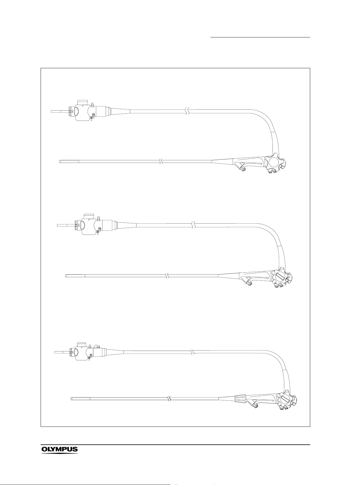
GIF-N180
GIF-Q180, GIF-H180
Chapter 1 Checking the Package Contents
Endoscope
CF-Q180AL/I, CF-H180AL/I, PCF-Q180AL/I
EVIS EXERA II GIF/CF/PCF TYPE 180 Series OPERATION MANUAL
Endoscope
Endoscope
13
Page 18
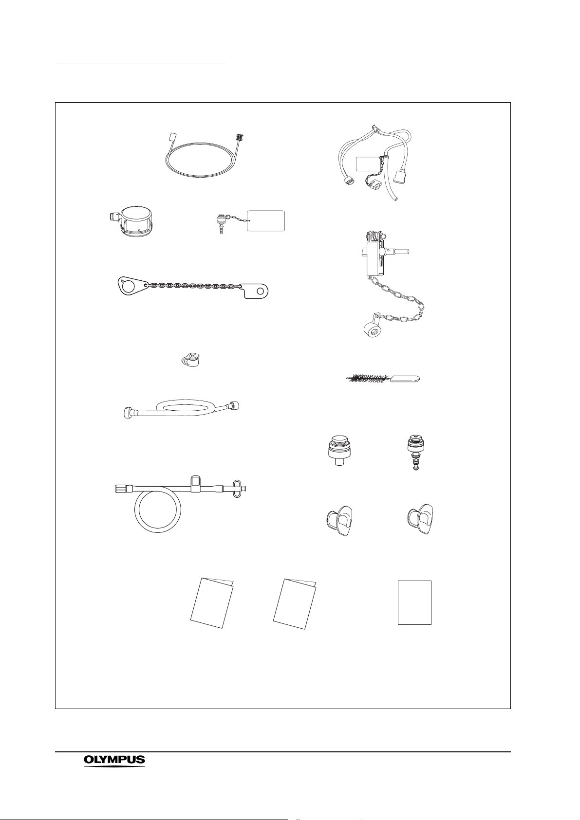
Chapter 1 Checking the Package Contents
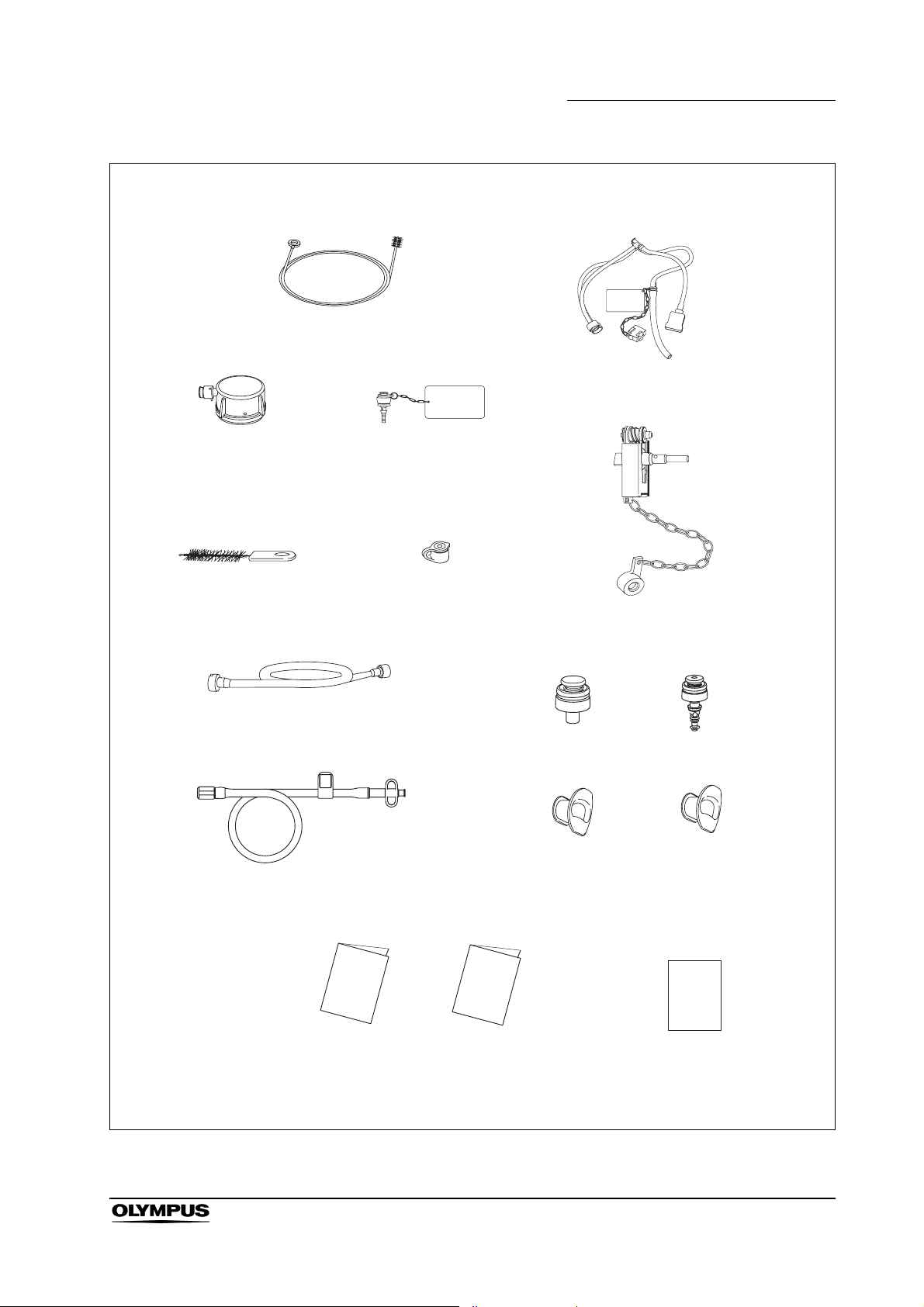
Packaged for the USA and CAN
Single use channel cleaning brush
(BW-201T) (3 pcs)
Injection tube (MH-946)
Water-resistant cap
(MH-553)
Chain for water-resistant cap
(MAJ-1119)
Biopsy valve
(MB-358) (10 pcs)
Suction cleaning adapter
(MH-856)
AW channel cleaning
adapter (MH-948)
Channel plug (MH-944)
Single use channel-opening
cleaning brush
(MAJ-1339) (3 pcs)
Suction valve
(MH-443) (2 pcs)
Air/water valve
(MH-438) (2 pcs)
14
Auxiliary water tube
(MAJ-855 for endoscopes with
auxiliary water feeding only)
Operation manual
EVIS EXERA II GIF/CF/PCF TYPE 180 Series OPERATION MANUAL
Mouthpiece
(MB-142 for GIF-Q180,
GIF-H180) (2 pcs)
Reprocessing manual
Mouthpiece
(MA-474, MB-142 for
GIF-N180) (1 pc each)
Instructions
(leaflet type, for
endoscopes with flexibility
adjustment only)
Page 19
Packaged for countries other than the USA and CAN
Channel cleaning brush (BW-20T)
Chapter 1 Checking the Package Contents
Injection tube (MH-946)
Water-resistant cap
(MH-553)
Channel-opening cleaning brush
(MH-507)
Suction cleaning adapter
(MH-856)
Auxiliary water tube
(MAJ-855 for endoscopes with
auxiliary water feeding only)
AW channel cleaning
adapter (MH-948)
Biopsy valve
(MB-358) (10 pcs)
Mouthpiece
(MB-142 for GIF-Q180,
GIF-H180) (2 pcs)
Channel plug (MH-944)
Suction valve
(MH-443) (2 pcs)
Air/water valve
(MH-438) (2 pcs)
Mouthpiece
(MA-474, MB-142 for
GIF-N180) (1 pc each)
Operation manual
Reprocessing manual
Instructions
(leaflet type, for
endoscopes with flexibility
adjustment only)
EVIS EXERA II GIF/CF/PCF TYPE 180 Series OPERATION MANUAL
15
Page 20
Chapter 2 Instrument Nomenclature and Specifications
Chapter 2 Instrument Nomenclature
and Specifications
2.1 Nomenclature
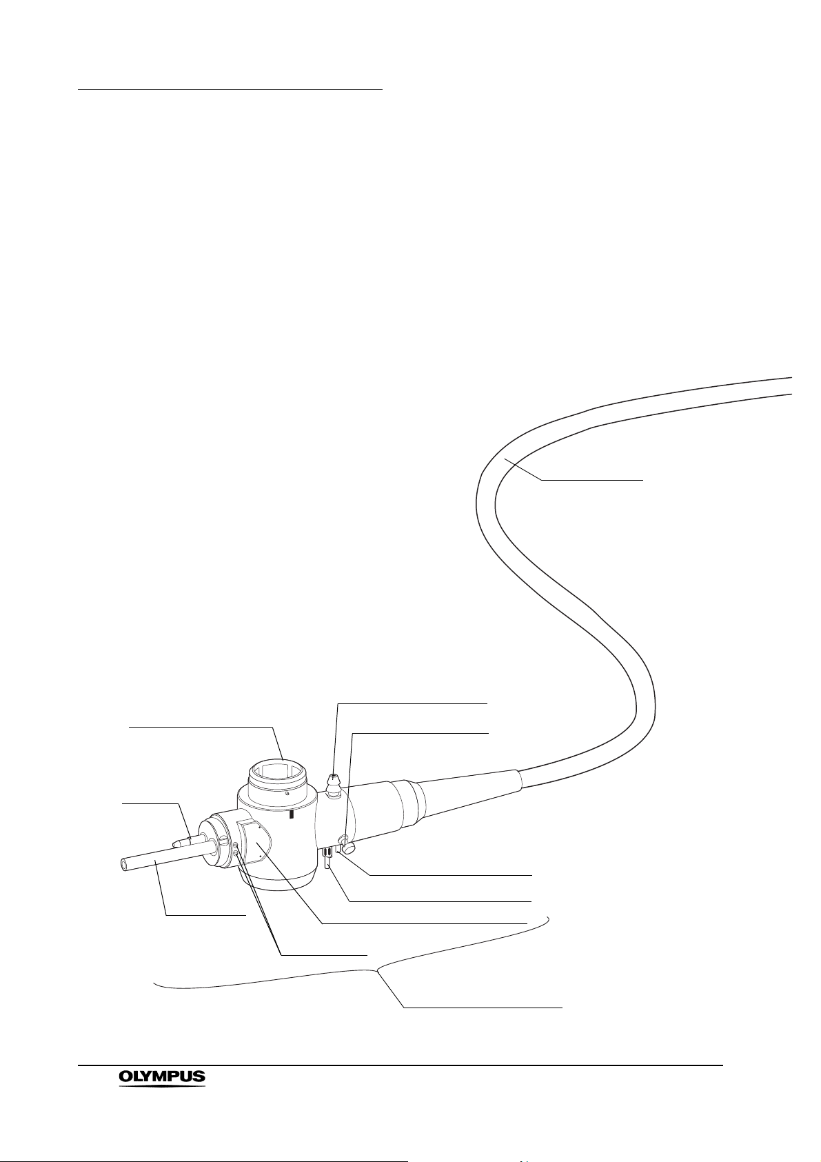
GIF-N180
Universal cord
16
5. Electrical connector
Air pipe
Light guide
EVIS EXERA II GIF/CF/PCF TYPE 180 Series OPERATION MANUAL
1. Suction connector
15. Chain connector
3. Air supply connector
3. Water supply connector
Product name and serial number
Contact pins
4. Endoscope connector
Page 21
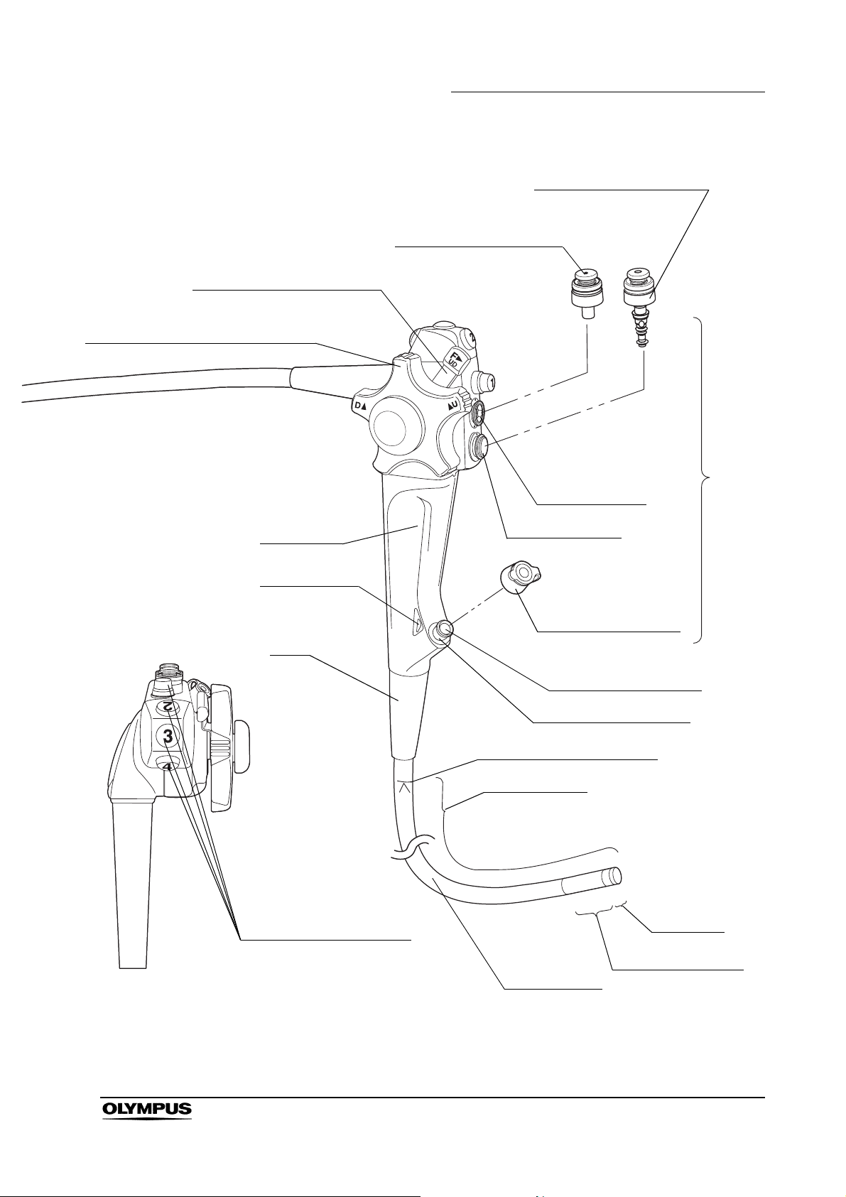
7. UP/DOWN angulation lock
6. UP/DOWN angulation control knob
Chapter 2 Instrument Nomenclature and Specifications
9. Air/water valve (MH-438)
8. Suction valve (MH-443)
Control
section
Suction cylinder
Grip section
14. Color code
Boot
13. Remote switches 1 to 4
Air/water cylinder
Biopsy valve (MB-358)
10. Instrument channel
Instrument channel port
11. Insertion tube limit mark
Working length
Distal end
12. Bending section
Insertion tube
EVIS EXERA II GIF/CF/PCF TYPE 180 Series OPERATION MANUAL
17
Page 22
Chapter 2 Instrument Nomenclature and Specifications
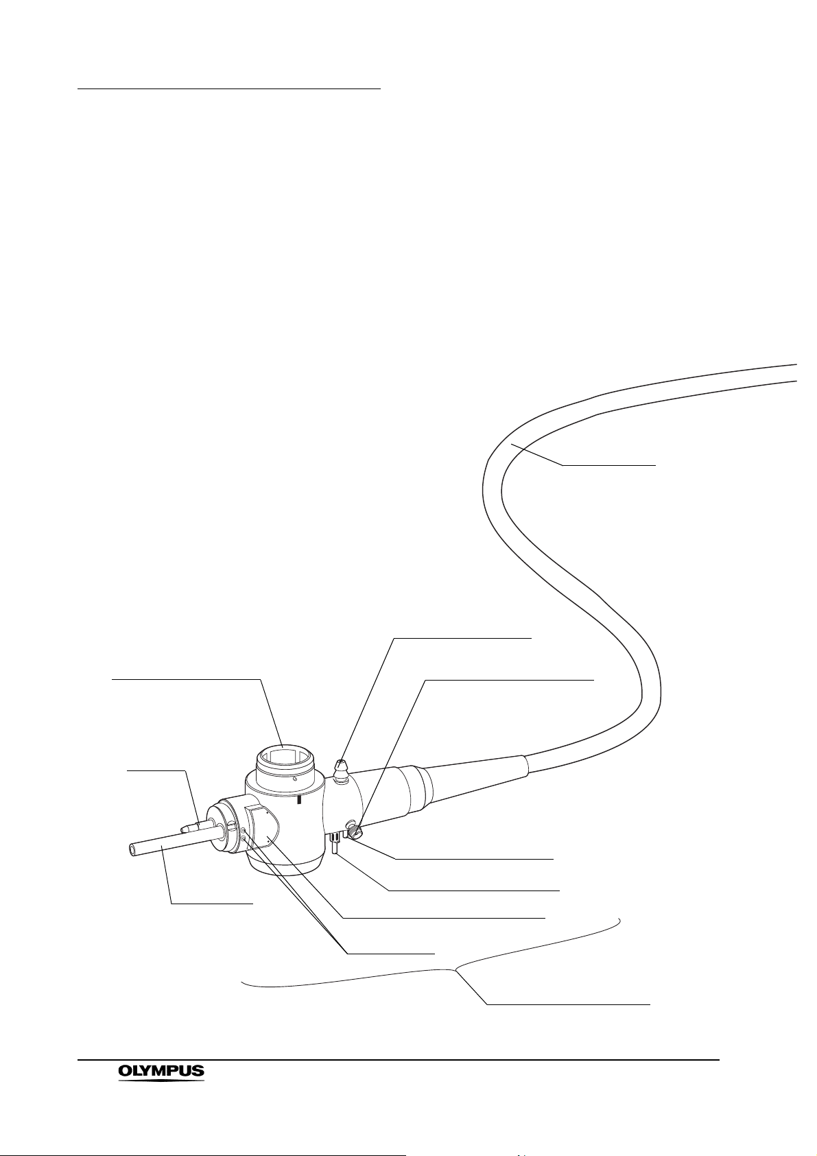
GIF-Q180, GIF-H180
Universal cord
5. Electrical connector
Air pipe
Light guide
1. Suction connector
2. S-cord connector mount
3. Air supply connector
3. Water supply connector
Product name and serial number
Contact pins
4. Endoscope connector
18
EVIS EXERA II GIF/CF/PCF TYPE 180 Series OPERATION MANUAL
Page 23
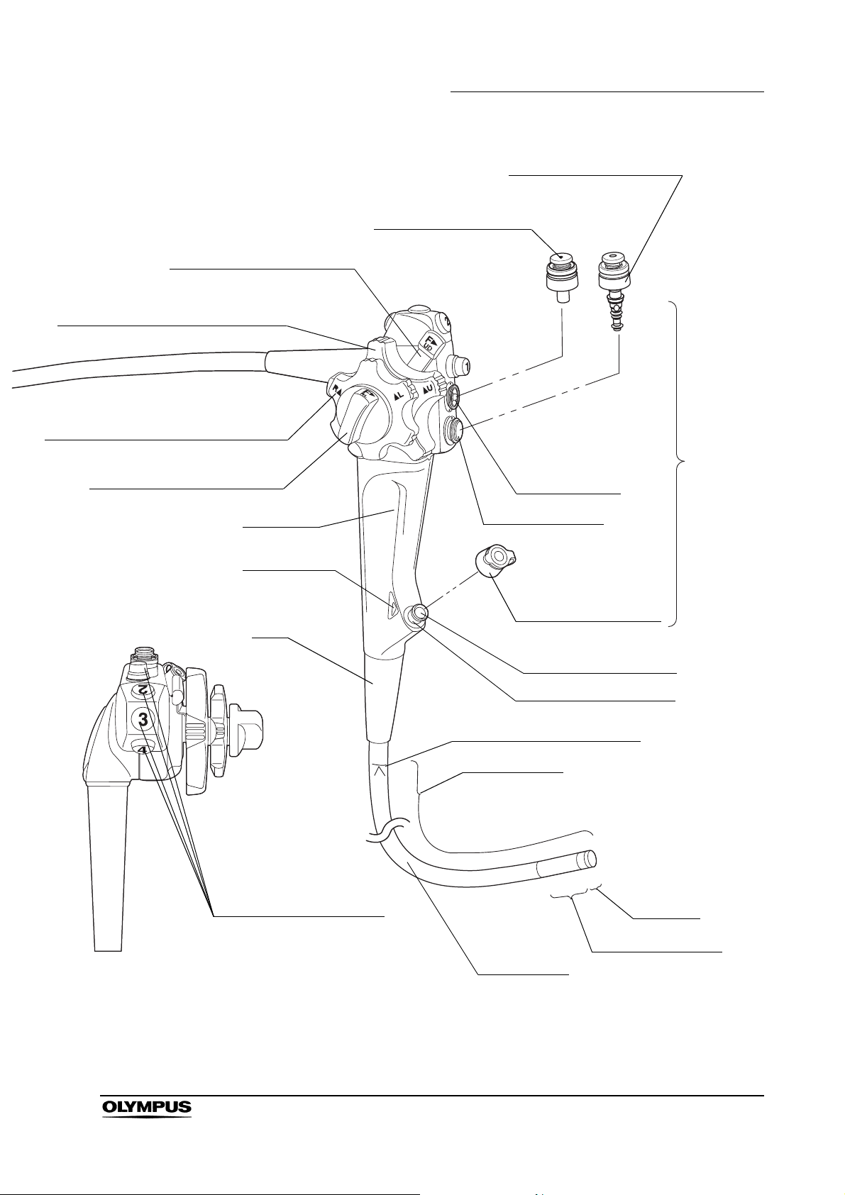
7. UP/DOWN angulation lock
6. UP/DOWN angulation control knob
17. RIGHT/LEFT angulation control knob
16. RIGHT/LEFT angulation lock
Chapter 2 Instrument Nomenclature and Specifications
9. Air/water valve (MH-438)
8. Suction valve (MH-443)
Control
section
Suction cylinder
Grip section
14. Color code
Boot
13. Remote switches 1 to 4
Air/water cylinder
Biopsy valve (MB-358)
10. Instrument channel
Instrument channel port
11. Insertion tube limit mark
Working length
Distal end
12. Bending section
Insertion tube
EVIS EXERA II GIF/CF/PCF TYPE 180 Series OPERATION MANUAL
19
Page 24
Chapter 2 Instrument Nomenclature and Specifications
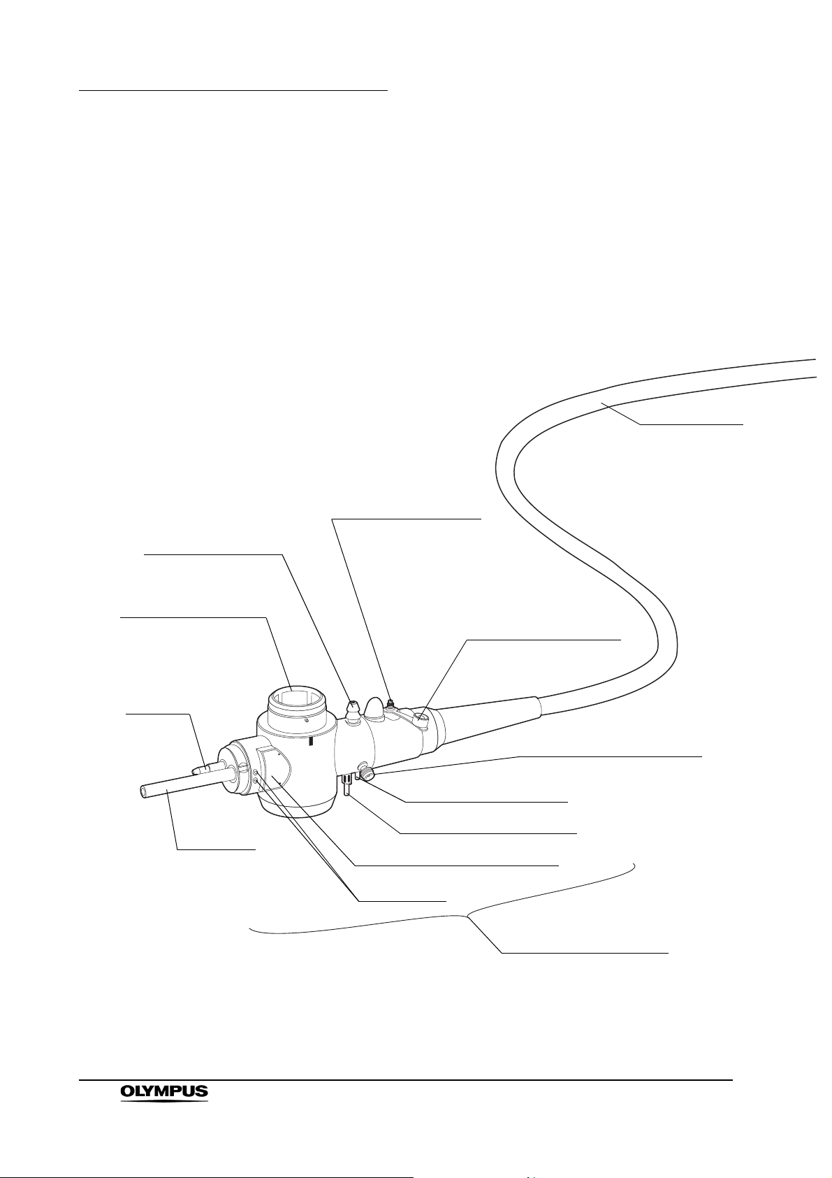
CF-Q180AL, CF-Q180AI, CF-H180AL, CF-H180AI,
PCF-Q180AL, PCF-Q180AI
Universal cord
1. Suction connector
5. Electrical connector
Air pipe
Light guide
19. Auxiliary water inlet
Auxiliary water inlet cap
(MAJ-215)
2. S-cord connector mount
3. Air supply connector
3. Water supply connector
Product name and serial number
Contact pins
20
4. Endoscope connector
EVIS EXERA II GIF/CF/PCF TYPE 180 Series OPERATION MANUAL
Page 25
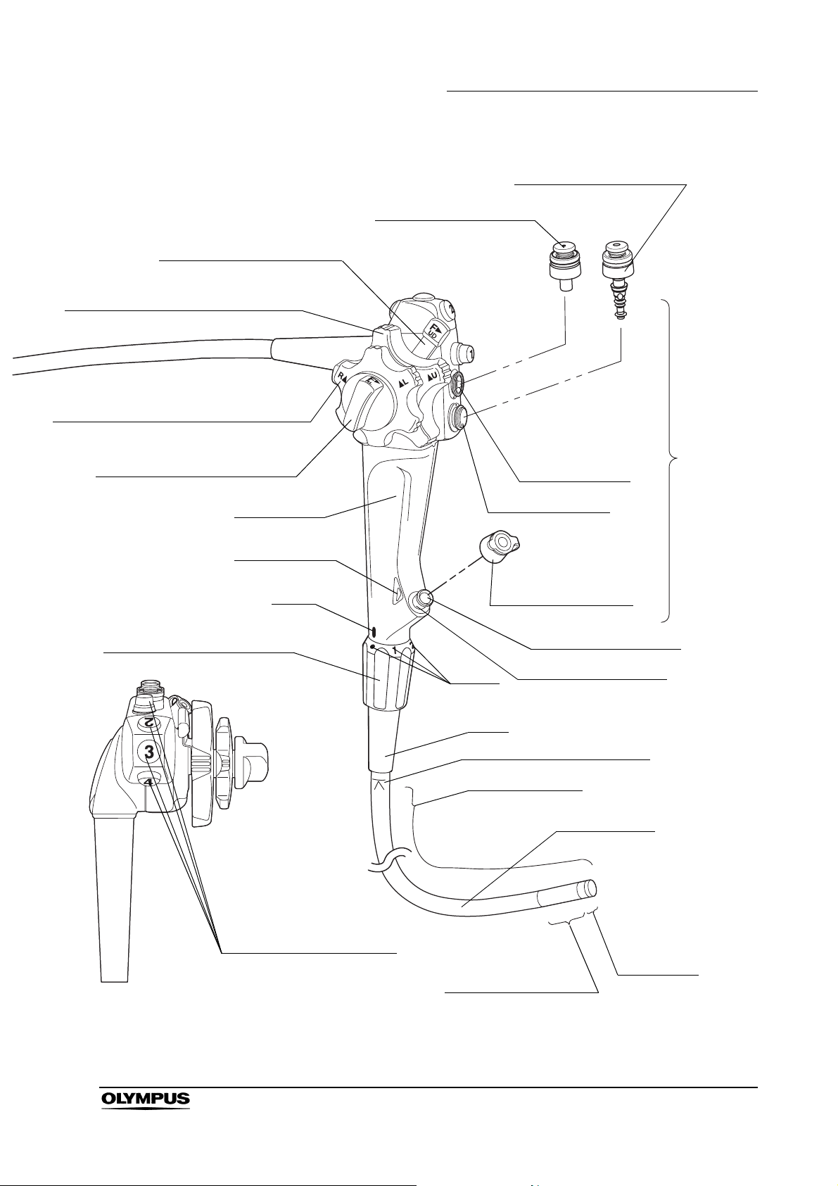
7. UP/DOWN angulation lock
6. UP/DOWN angulation control knob
17. RIGHT/LEFT angulation control knob
16. RIGHT/LEFT angulation lock
Chapter 2 Instrument Nomenclature and Specifications
9. Air/water valve (MH-438)
8. Suction valve (MH-443)
Suction cylinder
Control
section
Grip section
14. Color code
18. Flexibility adjustment ring
Mark
Air/water cylinder
Biopsy valve (MB-358)
10. Instrument channel
Marks
Boot
11. Insertion tube limit mark
Instrument channel port
Working length
Insertion tube
13. Remote switches 1 to 4
Distal end
12. Bending section
EVIS EXERA II GIF/CF/PCF TYPE 180 Series OPERATION MANUAL
21
Page 26

Chapter 2 Instrument Nomenclature and Specifications
2.2 Endoscope functions
1. Suction connector
Connects the endoscope to the suction tube of the suction pump.
2. S-cord connector mount (except GIF-N180)
Connects the endoscope with the Olympus electrosurgical unit via the
S-cord. The S-cord conducts leakage current from the endoscope to the
electrosurgical unit. To connect the S-cord, refer to the instruction manual
for the electrosurgical unit. Connect the fitting of the chain for
water-resistant cap to this mount as required (see Section 2.4 on page 32).
3. Water supply connector and air supply connector
Connects the endoscope to the water container via the water container
tube, to supply water to the distal end of the endoscope.
4. Endoscope connector
Connects the endoscope to the output socket of the light source and
transmits light from the light source to the endoscope.
5. Electrical connector
Connects the endoscope to the video system center via the videoscope
cable. The endoscope contains a memory chip that stores information about
the endoscope and communicates this information to the video system
center CV-160 and CV-180. For more details, refer to the instruction manual
of the CV-160 or CV-180.
6. UP/DOWN angulation control knob
When this knob is turned in the “ U” direction, the bending section moves
UP; when the knob is turned in the “D ” direction, the bending section
moves DOWN.
7. UP/DOWN angulation lock
Moving this lock in the “F ” direction frees angulation. Moving the lock in
the opposite direction locks the bending section at any desired position.
8. Suction valve (MH-443)
This valve is depressed to activate suction. The valve is used to remove any
fluid, debris, flatus or air from the patient.
9. Air/water valve (MH-438)
The hole in this valve is covered to insufflate air and the valve is depressed
to feed water for lens washing. It also can be used to feed air to remove any
fluid or debris adhering to the objective lens.
22
10. Instrument channel
The instrument channel functions as:
− channel for the insertion of endo-therapy accessories
− suction channel
− fluid feed channel (from a syringe via the biopsy valve)
EVIS EXERA II GIF/CF/PCF TYPE 180 Series OPERATION MANUAL
Page 27

Chapter 2 Instrument Nomenclature and Specifications
11. Insertion tube limit mark
This mark shows the maximum point to which the endoscope may be
inserted into the patient’s body.
12. Bending section
This section moves the distal end of the endoscope when the UP/DOWN
and RIGHT/LEFT angulation control knobs are operated (the GIF-N180 has
only the UP/DOWN angulation control knob).
13. Remote switches 1 to 4
The functions of the remote switches 1 to 4 can be selected on the video
system center. When selecting the functions, also refer to the instruction
manual for the video system center.
14. Color code
This code is used to quickly determine the compatibility of endo-therapy
accessories. The endoscope can be used with endo-therapy accessories
that have the same color code.
• Blue:
•Yellow:
• Orange:
GIF-N180
GIF-Q180, GIF-H180, PCF-Q180AL/I
CF-Q180AL/I, CF-H180AL/I
15. Chain connector (for GIF-N180 only)
Connect the fitting of the chain for water-resistant cap here. Do not connect
the S-cord of the electrosurgical unit here.
16. RIGHT/LEFT angulation lock (except GIF-N180)
Turning this lock in the “F ” direction frees angulation. Turning the lock in
the opposite direction locks the bending section at any desired position.
17. RIGHT/LEFT angulation control knob (except GIF-N180)
When this knob is turned in the “R ” direction, the bending section moves
RIGHT; when the knob is turned in the “ L” direction, the bending section
moves LEFT.
18. Flexibility adjustment ring (for endoscopes with flexibility adjustment only)
Turn this ring to adjust the flexibility of the insertion tube.
When the “z” mark on the ring is aligned with the “ ” mark at the bottom of
the grip section, the insertion tube is the most flexible. To decrease the
flexibility, turn the ring so that the numbers are aligned with the “ ” mark
(“3” corresponds to the most-rigid condition). As the ring is turned from “z”
to “3”, the insertion tube’s flexibility gradually decreases.
EVIS EXERA II GIF/CF/PCF TYPE 180 Series OPERATION MANUAL
23
Page 28

Chapter 2 Instrument Nomenclature and Specifications
19. Auxiliary water inlet (for endoscopes with auxiliary water feeding only)
Connect the auxiliary water tube here. Feed water from this inlet through the
auxiliary water channel when necessary, (e.g. when blood adheres to
mucous membrane in the patient’s body cavity). When the auxiliary water
inlet is not being used, make sure that it is covered by the auxiliary water
inlet cap.
2.3 Specifications
Environment
Operating
environment
Transportation and
storage
environment
Ambient temperature 10 – 40°C (50 – 104°F)
Relative humidity 30 – 85%
Atmospheric pressure 700 – 1060 hPa
(0.7 – 1.1 kgf/cm
(10.2 – 15.4 psia)
Ambient temperature –47 to 70°C (–52.6 to 158°F)
Relative humidity 10 – 95%
Atmospheric pressure 700 – 1060 hPa
(0.7 – 1.1 kgf/cm
(10.2 – 15.4 psia)
2
)
2
)
24
EVIS EXERA II GIF/CF/PCF TYPE 180 Series OPERATION MANUAL
Page 29
Specifications
Endoscope functions
Chapter 2 Instrument Nomenclature and Specifications
Model
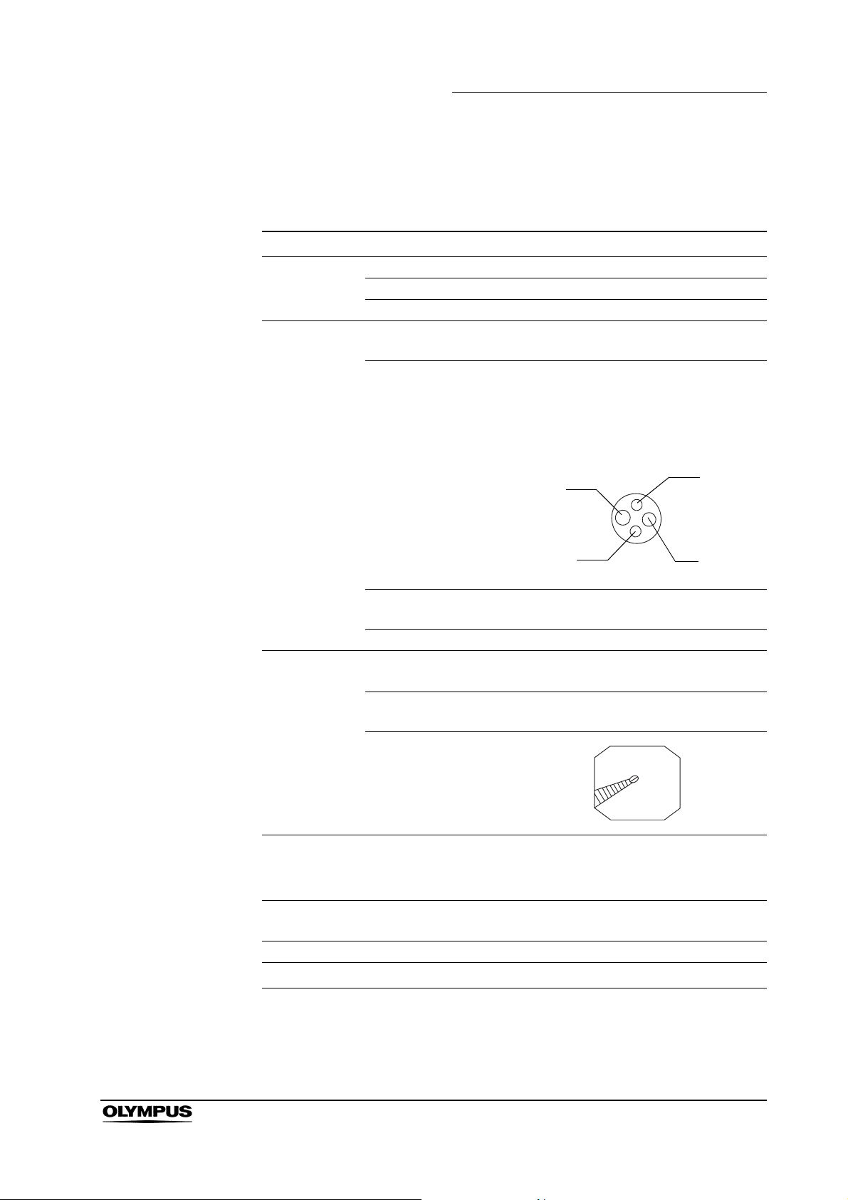
Optical system Field of view 120°
Direction of view Forward viewing
Depth of field 3 – 100 mm
Insertion tube Distal end outer
diameter
Distal end enlarged 1. Air/water nozzle
2. Light guide lens
3. Objective lens
4. Instrument channel outlet
RIGHT
Insertion tube outer
diameter
Working length 1100 mm
Instrument
channel
Air flow rate
Bending
section
Total length 1420 mm
∗
2
NBI
Channel inner
diameter
Minimum visible
distance
Direction from which
endo-therapy
accessories enter
and exit the
endoscopic image
Note: Standard when CLV-180 (high air
pressure) is used.
Angulation range
GIF-N180
ø4.9mm
3.
1.
2 mm from the distal end
UP 210°, DOWN 120°
UP
DOWN
ø4.9mm
ø2mm
3
25 cm
Available
∗1
2.
LEFT
4.
/s
∗1 GIF-N180 cannot be used to perform high-frequency cauterization or laser
cauterization.
∗2 NBI stands for Narrow Band Imaging. For more details, refer to the
instruction manual of the CV-180.
EVIS EXERA II GIF/CF/PCF TYPE 180 Series OPERATION MANUAL
25
Page 30
Chapter 2 Instrument Nomenclature and Specifications
Model GIF-Q180
Optical system Field of view 140°
Direction of view Forward viewing
Depth of field 3 – 100 mm
Insertion tube Distal end outer
diameter
Distal end enlarged 1. Air/water nozzle
ø8.8mm
2. Light guide lens
3. Objective lens
4. Instrument channel outlet
1.
UP
2.
Instrument
channel
Air flow rate
RIGHT
3.
DOWN
Insertion tube outer
diameter
ø8.8mm
Working length 1030 mm
Channel inner
diameter
Minimum visible
distance
3 mm from the distal end
ø2.8mm
Direction from which
endo-therapy
accessories enter
and exit the
endoscopic image
3
/s
25 cm
Note: Standard when CLV-180 (high air
pressure) is used.
LEFT
4.
26
Bending
section
Angulation range UP 210°, DOWN 90°,
RIGHT 100°, LEFT 100°
Total length 1345 mm
NBI
∗1
Available
∗1 NBI stands for Narrow Band Imaging. For more details, refer to the
instruction manual of the CV-180.
EVIS EXERA II GIF/CF/PCF TYPE 180 Series OPERATION MANUAL
Page 31

Chapter 2 Instrument Nomenclature and Specifications
Model GIF-H180
Optical system Field of view 140°
Direction of view Forward viewing
Depth of field 2 – 100 mm
Insertion tube Distal end outer
diameter
Distal end enlarged 1. Air/water nozzle
2. Light guide lens
3. Objective lens
4. Instrument channel outlet
1.
ø9.8mm
UP
2.
Instrument
channel
Air flow rate
RIGHT
3.
DOWN
Insertion tube outer
diameter
Working length 1030 mm
Channel inner
diameter
Minimum visible
distance
Direction from which
endo-therapy
accessories enter
and exit the
endoscopic image
Note: Standard when CLV-180 (high air
pressure) is used.
3 mm from the distal end
ø9.8mm
ø2.8mm
3
/s
25 cm
LEFT
4.
Bending
section
Total length 1345 mm
∗1
NBI
Angulation range UP 210°, DOWN 90°,
RIGHT 100°, LEFT 100°
Available
∗1 NBI stands for Narrow Band Imaging. For more details, refer to the
instruction manual of the CV-180.
EVIS EXERA II GIF/CF/PCF TYPE 180 Series OPERATION MANUAL
27
Page 32

Chapter 2 Instrument Nomenclature and Specifications
Model CF-Q180AL CF-Q180AI
Optical
system
Insertion tube Distal end outer
Field of view 170°
Direction of view Forward viewing
Depth of field 3 – 100 mm
diameter
Distal end enlarged 1. Air/water nozzle
ø13.2mm
2. Light guide lens
3. Objective lens
4. Instrument channel outlet
5. Auxiliary water channel
UP
5.
RIGHT
4.
3.
1.
LEFT
2.
DOWN
Instrument
channel
Air flow rate
Bending
section
Insertion tube outer
diameter
Working length L: 1680 mm I: 1330 mm
Range of the
flexibility adjustment
Channel inner
diameter
Minimum visible
distance
Direction from which
endo-therapy
accessories enter
and exit the
endoscopic image
Angulation range UP 180°, DOWN 180°,
The rigidity in the most-rigid condition is
about twice that in the most-flexible
condition.
Note: Standard when CLV-180 (high air
pressure) is used.
ø12.8mm
ø3.7mm
3 mm from the distal end
25 cm3/s
RIGHT 160°, LEFT 160°
28
Total length L: 2005 mm I: 1655 mm
NBI
∗1
Available
∗1 NBI stands for Narrow Band Imaging. For more details, refer to the
instruction manual of the CV-180.
EVIS EXERA II GIF/CF/PCF TYPE 180 Series OPERATION MANUAL
Page 33

Chapter 2 Instrument Nomenclature and Specifications
Model CF-H180AL CF-H180AI
Optical
system
Insertion tube Distal end outer
Field of view 170°
Direction of view Forward viewing
Depth of field 2 – 100 mm
diameter
Distal end enlarged 1. Air/water nozzle
2. Light guide lens
3. Objective lens
4. Instrument channel outlet
5. Auxiliary water channel
ø13.9mm
2.
1.
UP
3.
2.
Instrument
channel
RIGHT
4.
DOWN
Insertion tube outer
diameter
Working length L: 1680 mm I: 1330 mm
Range of the
flexibility adjustment
Channel inner
diameter
Minimum visible
distance
Direction from which
endo-therapy
accessories enter
and exit the
endoscopic image
The rigidity in the most-rigid condition is
about twice that in the most-flexible
condition.
ø12.8mm
ø3.7mm
3 mm from the distal end
LEFT
5.
Air flow rate
Note: Standard when CLV-180 (high air
pressure) is used.
Bending
section
Total length L: 2005 mm I: 1655 mm
∗1
NBI
Angulation range UP 180°, DOWN 180°,
RIGHT 160°, LEFT 160°
25 cm3/s
Available
∗1 NBI stands for Narrow Band Imaging. For more details, refer to the
instruction manual of the CV-180.
EVIS EXERA II GIF/CF/PCF TYPE 180 Series OPERATION MANUAL
29
Page 34

Chapter 2 Instrument Nomenclature and Specifications
Model PCF-Q180AL PCF-Q180AI
Optical system Field of view 140°
Direction of view Forward viewing
Depth of field 3 – 100 mm
Insertion tube Distal end outer
diameter
Distal end enlarged 1. Air/water nozzle
ø11.3mm
2. Light guide lens
3. Objective lens
4. Instrument channel
5. Auxiliary water channel
UP
RIGHT
4.
DOWN
3.
1.
5.
LEFT
2.
Instrument
channel
Air flow rate
Bending
section
Insertion tube outer
diameter
Working length L: 1680 mm I: 1330 mm
Range of the
flexibility adjustment
Channel inner
diameter
Minimum visible
distance
Direction from which
endo-therapy
accessories enter
and exit the
endoscopic image
Angulation range UP 180°, DOWN 180°,
The rigidity in the most-rigid condition is
about twice that in the most-flexible
Note: Standard when CLV-180 (high air
pressure) is used.
ø11.5mm
condition.
ø3.2mm
5 mm from the distal end
3
/s
25 cm
RIGHT 160°, LEFT 160°
30
Total length L: 2005 mm I: 1655 mm
NBI
∗1
Available
∗1 NBI stands for Narrow Band Imaging. For more details, refer to the
instruction manual of the CV-180.
EVIS EXERA II GIF/CF/PCF TYPE 180 Series OPERATION MANUAL
Page 35

Chapter 2 Instrument Nomenclature and Specifications
Medical Device
Directive
EMC Applied standard;
IEC 60601-1-2: 2001
Year of
manufacture
2512345
This device complies with the requirements
of Directive 93/42/EEC concerning medical
devices. Classification: Class II a
This instrument complies with the
standards listed in the left column.
CISPR 11 of emission:
Group 1, Class B
This instrument complies with the EMC
standard for medical electrical equipment;
edition 2 (IEC 60601-1-2: 2001). However,
when connecting to an instrument that
complies with the EMC standard for
medical electrical equipment; edition 1
(IEC 60601-1-2: 1993), the whole system
complies with edition 1.
The last digit of the year of manufacture is
the second digit of the serial number.
Degree of
protection
against
electric shock
TYPE BF applied part
EVIS EXERA II GIF/CF/PCF TYPE 180 Series OPERATION MANUAL
31
Page 36

Chapter 2 Instrument Nomenclature and Specifications
2.4 Attaching the chain for water-resistant cap (MAJ-1119)
• Do not lift the endoscope by the chain for water-resistant cap.
Otherwise, operator and/or patient injury can result, or the
endoscope and/or water-resistant cap may be damaged
when the fitting comes off the S-cord connector mount or the
chain connector of the GIF-N180.
• Only connect the fitting to the S-cord connector mount or the
chain connector of the GIF-N180. Connecting the fitting to
the suction connector may impair the connection of the
suction tube to the suction connector. It may also cause the
suction tube to become disconnected from the endoscope
and allow patient debris to spray.
• The chain for water-resistant cap and water-resistant cap
itself cannot be ultrasonically cleaned; doing so could
damage them. The water-resistant cap with the chain can
only be ultrasonically cleaned if connected to endoscopes
that are being cleaned in an endoscope reprocessor (such as
OER) with an ultrasonic cleaning phase.
• When attaching the water-resistant cap to the electrical
connector, do not pinch the chain for water-resistant cap
between the electrical connector of the endoscope and the
water-resistant cap. Otherwise, equipment damage may
result.
• The chain for water-resistant cap and water-resistant cap
cannot be ETO gas sterilized; doing so may damage them. If
the water-resistant cap is connected to the endoscope by the
chain, be sure to remove the chain and the water-resistant
cap from the endoscope before ETO gas sterilization.
32
EVIS EXERA II GIF/CF/PCF TYPE 180 Series OPERATION MANUAL
Page 37

Chapter 2 Instrument Nomenclature and Specifications
• The chain for water-resistant cap and water-resistant cap
cannot be steam sterilized (autoclaved); doing so can
damage them severely.
Notch
Figure 2.1
Chain part
Fitting part
Connecting plate
To ensure that you do not forget to attach the water-resistant
cap, it is recommended that you connect it to the
endoscope’s S-cord connector mount or the chain connector
of the GIF-N180 using the chain for water-resistant cap.
Hole
1. Confirm that the chain for water-resistant cap is free from cracks, flaws,
wear, deformation or other damages (see Figure 2.1).
2. Align the notch on the connecting plate with the pin on the venting connector
of the water-resistant cap (MH-553, see Figure 2.2).
3. Place the connecting plate over the venting connector (see Figure 2.2).
4. Confirm that the connecting plate is securely attached to the foot of the
venting connector and can be smoothly rotated.
5. Place the hole on the fitting over the endoscope’s S-cord connector mount
or the chain connector of the GIF-N180 (see Figure 2.3).
EVIS EXERA II GIF/CF/PCF TYPE 180 Series OPERATION MANUAL
33
Page 38

Chapter 2 Instrument Nomenclature and Specifications
6. Confirm that the fitting is securely attached to the foot of the S-cord
connector mount or the chain connector of the GIF-N180 and can be
smoothly rotated.
Connecting plate
Venting connector
Water-resistant cap
Figure 2.2
Notch
Pin
Fitting part
Hole
S-cord connector
mount or chain
connector
34
Figure 2.3
The instructions on the remaining pages of this manual are
given under the assumption that the chain for the
water-resistant cap is detached from the endoscope.
EVIS EXERA II GIF/CF/PCF TYPE 180 Series OPERATION MANUAL
Page 39

Chapter 3 Preparation and Inspection
Chapter 3 Preparation and Inspection
Before each case, prepare and inspect this instrument as instructed below.
Inspect other equipment to be used with this instrument as instructed in their
respective instruction manuals. If any irregularities are suspected after
inspection, follow the instructions as described in Chapter 5, “Troubleshooting”.
If this instrument malfunctions, do not use it. Return it to Olympus for repair as
described in Section 5.3, “Returning the endoscope for repair” on page 86.
• Using an endoscope that is not functioning properly may
compromise patient or operator safety and may result in
more severe equipment damage.
• This instrument was not cleaned, disinfected or sterilized
before shipment. Before using this instrument for the first
time, reprocess it according to the instructions as described
in the endoscope’s companion manual, the
“REPROCESSING MANUAL” whose cover lists the model of
your endoscope.
EVIS EXERA II GIF/CF/PCF TYPE 180 Series OPERATION MANUAL
35
Page 40

Chapter 3 Preparation and Inspection
3.1 Preparation of the equipment
Prepare the equipment shown in Figure 3.1 (for compatibility, see the “System
chart” in the Appendix) and personal protective equipment, such as eye wear,
face mask, moisture-resistant clothing and chemical-resistant gloves, before
each use. Refer to the respective instruction manuals for each piece of
equipment.
Video monitor
Video system center
Light source
Water container
Endo-therapy accessories
Suction pump
Endoscope
Water pump (OFP) or a
syringe (for endoscopes with
auxiliary water feeding only)
Mouthpiece
(for GIF models only)
Auxiliary water tube
(for endoscopes with
auxiliary water feeding only)
• Paper towels • Trays • Lint-free cloths • Personal protective equipment
Figure 3.1
36
EVIS EXERA II GIF/CF/PCF TYPE 180 Series OPERATION MANUAL
Page 41

3.2 Inspection of the endoscope
Clean and disinfect or sterilize the endoscope as described in the
“REPROCESSING MANUAL” whose cover lists the model of your endoscope.
Then remove the water-resistant cap from the endoscope connector.
Inspection of the endoscope
Inspect the control section and the endoscope connector for excessive
1.
scratching, deformation, loose parts or other irregularities.
2. Inspect the boot and the insertion tube near the boot for bends, twists or
other irregularities.
3. Inspect the external surface of the entire insertion tube including the
bending section and the distal end for dents, bulges, swelling, scratching,
holes, sagging, transformation, bends, adhesion of foreign bodies, dropout
of parts, any protruding objects or other irregularities.
Chapter 3 Preparation and Inspection
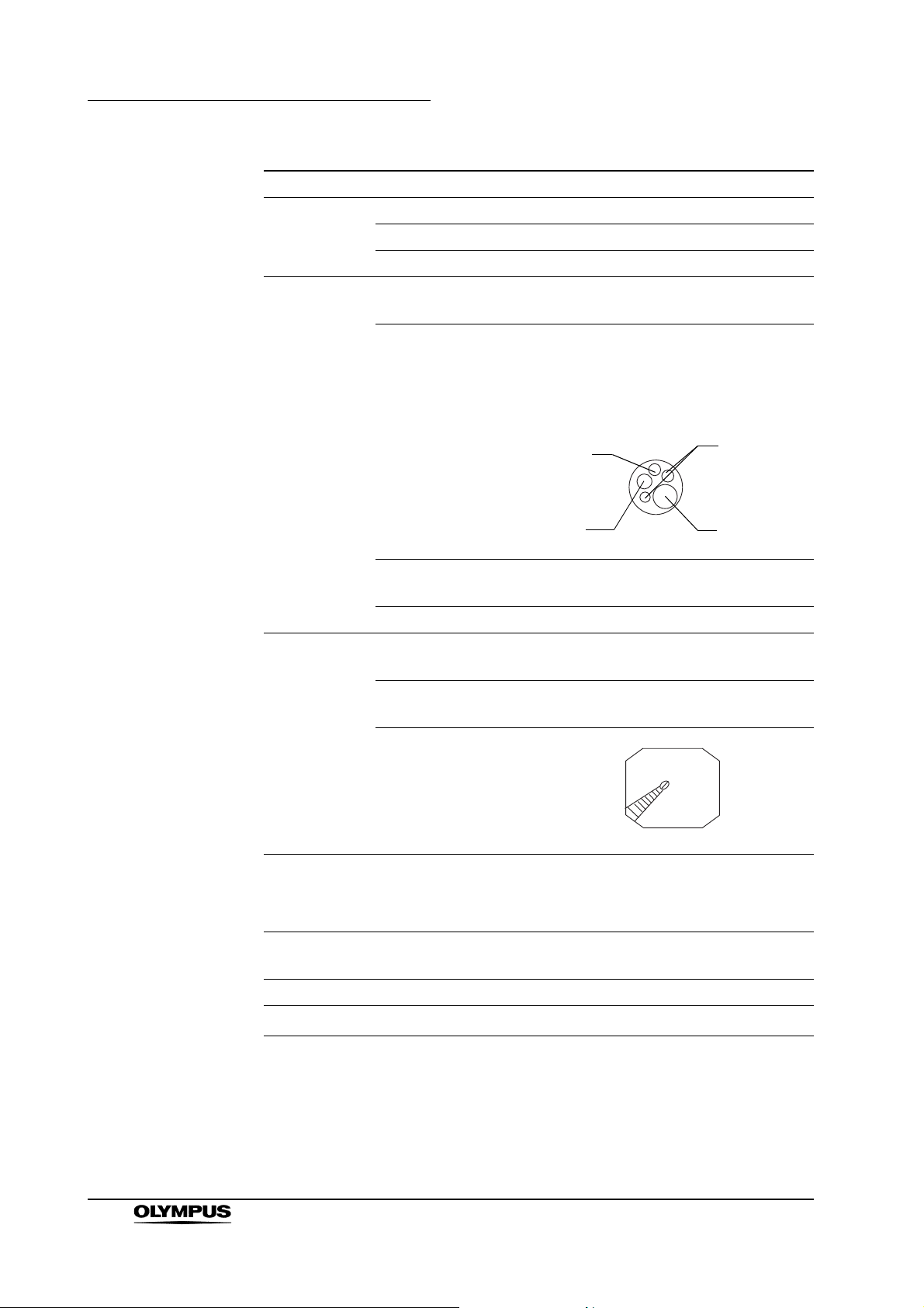
4. Holding the insertion tube gently with one hand, carefully run your fingertips
over the entire length of the insertion tube in both directions (see Figure
3.2). Confirm that no objects or metallic wire protrude from the insertion
tube. Also confirm that the insertion tube is not abnormally rigid.
Figure 3.2
5. Using both hands, bend the insertion tube of the endoscope into a
semicircle. Then, moving your hands as shown by the arrows in Figure 3.3,
confirm that the entire insertion tube can be smoothly bent to form a
semicircle and that the insertion tube is pliable. When inspecting
endoscopes with flexibility adjustment, perform the test with the insertion
tube at both its most-flexible and most-rigid settings (for endoscopes with
flexibility adjustment only).
EVIS EXERA II GIF/CF/PCF TYPE 180 Series OPERATION MANUAL
37
Page 42

Chapter 3 Preparation and Inspection
Figure 3.3
6. Gently hold the midpoint of the bending section and a point 20 cm from the
distal end. Push and pull gently to confirm that the junction between the
bending section and the insertion tube is not loose.
7. Inspect the objective lens and light guide lens at the distal end of the
endoscope’s insertion tube for scratching, cracks, stains or other
irregularities.
8. Inspect the air/water nozzle at the distal end of the endoscope’s insertion
tube for abnormal swelling, bulges, dents or other irregularities.
Inspection of the flexibility adjustment mechanism (for endoscopes with flexibility adjustment only)
Confirm that the marks (“z”, “1”, “2”, “3”) on the flexibility adjustment ring
1.
and the “ ” mark at the bottom of the grip section are clearly visible (see
Figure 3.4).
38
Figure 3.4
EVIS EXERA II GIF/CF/PCF TYPE 180 Series OPERATION MANUAL
Page 43

Chapter 3 Preparation and Inspection
Do not use the endoscope if the markings are not clearly
visible. If the operator is uncertain of the flexibility of the
endoscope, insertion and manipulation of the endoscope
may cause patient pain and/or injury.
2. Confirm that the flexibility adjustment ring can be turned smoothly when the
insertion tube is straight.
If the insertion tube is coiled into a too small diameter, the
flexibility adjustment ring may not operate smoothly. This
does not indicate a malfunction.
3. Set the insertion tube to the most-flexible and most-rigid conditions,
respectively. In each case, hold the marks of 30 and 50 cm of the insertion
tube with two hands, and bend it gently as shown in Figure 3.5. Confirm that
the actual flexibility changes according to the flexibility adjustment setting.
Figure 3.5
50 cm
30 cm
EVIS EXERA II GIF/CF/PCF TYPE 180 Series OPERATION MANUAL
39
Page 44

Chapter 3 Preparation and Inspection
Inspection of the bending mechanisms
Perform the following inspections while the bending section is straight.
• If the movement of the UP/DOWN angulation lock,
RIGHT/LEFT angulation lock and their angulation control
knobs are loose and/or not smooth, or the bending section
does not angulate smoothly, the bending mechanism may be
abnormal. In this case, do not use the endoscope because it
may be impossible to straighten the bending section during
an examination (except GIF-N180).
• If the movement of the UP/DOWN angulation lock and its
angulation control knob are loose and/or not smooth, or the
bending section does not angulate smoothly, the bending
mechanism may be abnormal. In this case, do not use the
endoscope because it may be impossible to straighten the
bending section during an examination (for GIF-N180 only).
Inspection for smooth operation
1. Confirm that both the UP/DOWN and RIGHT/LEFT angulation locks move
all the way in the “F ” direction (the GIF-N180 has only the UP/DOWN
angulation lock).
2. Turn the UP/DOWN and RIGHT/LEFT angulation control knobs slowly in
each direction until they stop, and return them to their respective neutral
positions (the GIF-N180 has only the UP/DOWN angulation control knob).
Confirm that the bending section angulates smoothly and correctly, that
maximum angulation can be achieved, and that the bending section returns
to its neutral position.
40
EVIS EXERA II GIF/CF/PCF TYPE 180 Series OPERATION MANUAL
Page 45

Chapter 3 Preparation and Inspection
3. When the UP/DOWN and RIGHT/LEFT angulation control knobs are turned
to their respective neutral positions as shown in Figure 3.6, confirm that the
bending section returns smoothly to an approximately straight condition
(except GIF-N180).
Figure 3.6
4. When the UP/DOWN angulation control knob is turned to its neutral position
as shown in Figure 3.7, confirm that the bending section returns smoothly to
an approximately straight condition (for GIF-N180 only).
Figure 3.7
EVIS EXERA II GIF/CF/PCF TYPE 180 Series OPERATION MANUAL
41
Page 46

Chapter 3 Preparation and Inspection
Inspection of the UP/DOWN angulation mechanism
1. Move the UP/DOWN angulation lock all the way in the opposite direction of
the “F ” mark. Then turn the UP/DOWN angulation control knob in the
“ U” or the “D ” direction until it stops.
2. Confirm that the angle of the bending section is roughly stabilized when the
UP/DOWN angulation control knob is released.
3. Confirm that the bending section straightens out when the UP/DOWN
angulation lock is moved all the way in the “F ” direction and the
UP/DOWN angulation control knob is released.
Inspection of the RIGHT/LEFT angulation mechanism
(except GIF-N180)
1. Turn the RIGHT/LEFT angulation lock all the way in the opposite direction of
the “F ” mark. Then turn the RIGHT/LEFT angulation control knob in the
“R ” or the “ L” direction until it stops.
2. Confirm that the angle of the bending section is roughly stabilized when the
RIGHT/LEFT angulation control knob is released.
3. Confirm that the bending section straightens out when the RIGHT/LEFT
angulation lock is turned in the “F ” direction and the RIGHT/LEFT
angulation control knob is released.
42
EVIS EXERA II GIF/CF/PCF TYPE 180 Series OPERATION MANUAL
Page 47

Chapter 3 Preparation and Inspection
3.3 Preparation and inspection of accessories
Clean and disinfect or sterilize the air/water valve, suction valve, biopsy valve
and auxiliary water tube as described in the endoscope’s companion
reprocessing manual, the “REPROCESSING MANUAL” whose cover lists the
model of your endoscope.
Inspection of the air/water and suction valves
Confirm that the top hole of the air/water valve is not blocked
(see Figure 3.8). If the hole is blocked, air is fed continuously
and patient pain, bleeding and/or perforation can result.
1. Confirm that the holes of the valves are not blocked (see Figures 3.8 and
3.9).
2. Confirm that the valves are not deformed or cracked (see Figures 3.8 and
3.9).
3. Check for excessive scratching or tears in the air/water valve’s seals (see
Figure 3.8).
Hole
Spring
Seals
Air/water valve (MH-438)
Figure 3.8
Skirt
Hole
EVIS EXERA II GIF/CF/PCF TYPE 180 Series OPERATION MANUAL
43
Page 48

Chapter 3 Preparation and Inspection
Figure 3.9
Spring
Skirt
Hole
Suction valve (MH-443)
The air/water and suction valves are consumable items. If the
inspection of the air/water or suction valve reveals any
irregularities, use new valves.
Inspection of the biopsy valve
The biopsy valve is a consumable item that should be
inspected before each use. Replace it with a new one if
irregularities are observed during the following inspection. An
irregular, abnormal or damaged valve can reduce the
efficacy of the endoscope’s suction system, and may leak or
spray patient debris or fluids, posing an infection-control risk.
1. Confirm that the slit and hole on the biopsy valve have no splits, cracks,
deformation, discoloration or other damage (see Figure 3.10).
Normal
Slit
Hole
Cap
Main body
Abnormal
Discoloration
Splits, Cracks
44
Figure 3.10
EVIS EXERA II GIF/CF/PCF TYPE 180 Series OPERATION MANUAL
Page 49

Chapter 3 Preparation and Inspection
2. Attach the cap to the main body (see Figure 3.11).
Slit
Cap
Figure 3.11
Main body
Inspection of the auxiliary water inlet cap (for endoscopes with auxiliary water feeding only)
Confirm that the auxiliary water inlet cap attached to the endoscope
1.
connector has no dents, cracks or other irregularities (see Figure 3.12).
2. If irregularities are observed, replace it with a new one as described in
“Attaching the auxiliary water inlet cap (for endoscopes with auxiliary water
feeding only)” on page 49.
Auxiliary water inlet
Endoscope connector
Auxiliary water inlet cap
Figure 3.12
EVIS EXERA II GIF/CF/PCF TYPE 180 Series OPERATION MANUAL
45
Page 50

Chapter 3 Preparation and Inspection
Inspection of the auxiliary water tube (for endoscopes with auxiliary water feeding only)
Inspect the auxiliary water tube for cracks, scratches, flaws and other damage
(see Figure 3.13).
Figure 3.13
Clip
Luer port
Inspection of the mouthpiece (for GIF models only)
Do not use a mouthpiece that is damaged, deformed or
reveals other irregularities. Doing so may cause patient injury
and/or equipment damage.
Placing the mouthpiece in the patient’s mouth before the
procedure prevents the patient from biting and/or damaging
the endoscope’s insertion tube.
1. Confirm that the mouthpiece is free from cracks, deformation or
discoloration (see Figure 3.14).
2. Using your fingers, check for excessive scratching or other irregularities on
all surfaces of the mouthpiece (see Figure 3.14).
46
EVIS EXERA II GIF/CF/PCF TYPE 180 Series OPERATION MANUAL
Page 51

Opening
Chapter 3 Preparation and Inspection
Main body
Figure 3.14
Outer flange
3.4 Attaching accessories to the endoscope
The air/water valve and the suction valve do not require
lubrication. Lubricants can cause swelling of the valves’
seals, which will impair valve function.
Attaching the suction valve
Align the two metal ridges on the underside of the suction valve with the two
1.
holes in the suction cylinder.
2. Attach the suction valve to the suction cylinder of the endoscope (see
Figures 3.15 and 3.16). Confirm that the valve fits properly without any
bulging of the skirt. Also confirm that the valve cannot be rotated.
EVIS EXERA II GIF/CF/PCF TYPE 180 Series OPERATION MANUAL
47
Page 52

Chapter 3 Preparation and Inspection
Figure 3.15
Skirt
Side view
Two metal ridges
Bottom view
The suction valve will make a whistling noise when it is dry;
this does not indicate a malfunction.
Suction cylinder
Suction cylinder
Two holes
Top view
Attaching the air/water valve
Attach the air/water valve to the air/water cylinder of the endoscope (see
1.
Figure 3.16).
2. Confirm that the valve fits properly without any bulging of the skirt.
Air/water valve
Suction valve
Skirt
Suction cylinder
Air/water cylinder
Figure 3.16
48
The air/water valve may stick at first, but it should operate
smoothly after it is depressed a few times.
EVIS EXERA II GIF/CF/PCF TYPE 180 Series OPERATION MANUAL
Page 53

Attaching the biopsy valve
If a biopsy valve is not properly connected to the instrument
channel port, it can reduce the efficacy of the endoscope’s
suction system and may cause patient debris to leak or spray
from the endoscope.
Attach the biopsy valve to the instrument channel port of the endoscope (see
Figure 3.17). Confirm that the biopsy valve fits properly.
Biopsy valve
Instrument
channel port
Chapter 3 Preparation and Inspection
Figure 3.17
Attaching the auxiliary water inlet cap (for endoscopes with auxiliary water feeding only)
If the auxiliary water inlet cap is not attached, attach the fitting ring to the
auxiliary water inlet on the endoscope connector (see Figure 3.18).
Fitting ring
Auxiliary water inlet
Endoscope connector
Figure 3.18
Auxiliary water inlet cap
EVIS EXERA II GIF/CF/PCF TYPE 180 Series OPERATION MANUAL
49
Page 54

Chapter 3 Preparation and Inspection
3.5 Inspection and connection of ancillary equipment
Inspection of ancillary equipment
• Attach the water container to the specified receptacle on the
trolley or the light source. If the water container is attached
anywhere else, water may drip from the water container’s
water supply tube, and equipment malfunction can result.
• Take care not to spill water from the water container’s
connection adapter when detaching the connection adapter
from the endoscope. Spilled water could splash on the
equipment, and it may cause equipment malfunction.
Prepare and inspect the light source, video system center, video monitor, water
container, suction pump and endo-therapy accessories as described in their
respective instruction manuals.
Connection of the endoscope and ancillary equipment
Firmly connect the suction tube from the suction pump to the
suction connector on the endoscope connector. If the suction
tube is not attached properly, debris may drip from the tube
and can present an infection-control risk, damage and/or
reduce suction capability.
The CV-100 is not compatible with the GIF-N180. If the
GIF-N180 is used with the CV-100, the endoscopic image
may not appear on the video monitor.
The GIF-H180 and CF-H180AL/I can only be connected to
the CV-180.
1. If any ancillary equipment is ON, turn it OFF.
2. Insert the endoscope connector completely into the scope socket (output
socket when using the CLV-U40) of the light source.
3. Connect the water container’s connection adapter to the air supply
connector and water supply connector (see Figure 3.19).
50
4. Confirm that the water container’s connection adapter fits properly and that
it cannot be rotated.
EVIS EXERA II GIF/CF/PCF TYPE 180 Series OPERATION MANUAL
Page 55

Chapter 3 Preparation and Inspection
(1) (2) (3) (4)
Air supply connector
Water supply connector
Water container’s connection adapter
Endoscope connector
Figure 3.19
5. Align the mark on the videoscope cable EXERA II, the videoscope cable
EXERA or the videoscope cable 100 with mark 1 on the endoscope
connector and push it in until it stops (see Figure 3.20).
Mark 2 (yellow)
Mark 1 (yellow)
Figure 3.20
Mark (yellow)
6. Turn the connector of the videoscope cable clockwise until it stops (see
Figure 3.20).
7. Confirm that the mark on the videoscope cable is aligned with mark 2 on the
endoscope connector.
EVIS EXERA II GIF/CF/PCF TYPE 180 Series OPERATION MANUAL
51
Page 56

Chapter 3 Preparation and Inspection
8. Connect the suction tube from the suction pump to the suction connector on
the endoscope connector (see Figure 3.21).
Figure 3.21
Suction pump
Suction connector
Suction tube
9. Open the auxiliary water inlet cap (for endoscopes with auxiliary water
feeding only, see Figure 3.22).
10. Connect the auxiliary water tube to the auxiliary water inlet on the
endoscope connector and turn it clockwise until it stops (for endoscopes
with auxiliary water feeding only, see Figure 3.22).
Auxiliary water tube
Auxiliary water inlet
Endoscope connector
Auxiliary water inlet cap
52
Figure 3.22
EVIS EXERA II GIF/CF/PCF TYPE 180 Series OPERATION MANUAL
Page 57

Chapter 3 Preparation and Inspection
3.6 Inspection of the endoscopic system
Inspection of the endoscopic image
Do not stare directly at the distal end of the endoscope while
the examination light is ON. Otherwise, eye injury may result.
1. Turn the video system center, light source, video monitor ON and inspect
the endoscopic image as described in their respective instruction manuals.
2. Confirm that light is output from the endoscope’s distal end.
3. While observing the palm of your hand, confirm that the endoscopic image
is free from noise, blur, fog or other irregularities.
4. Angulate the endoscope and confirm that the endoscopic image does not
momentarily disappear or displays any other irregularities.
If the object cannot be seen clearly, wipe the objective lens
using a clean lint-free cloth moistened with 70% ethyl or
isopropyl alcohol.
Inspection of remote switch
All remote control switches should be checked to work
normally even when they are not expected for use. The
endoscopic image may freeze or other irregularities may
occur during examination and may cause patient injury,
bleeding and/or perforation.
Depress every remote control switch and confirm that the specified functions
work normally.
Inspection of the air feeding function
Set the airflow regulator on the light source to “High”, as described in the
1.
light source’s instruction manual.
2. Immerse the distal end of the insertion tube in sterile water to a depth of
10 cm and confirm that no air bubbles are emitted when the air/water valve
is not operated.
3. Cover the hole in the air/water valve with your finger and confirm that air
bubbles are continuously emitted from the air/water nozzle.
EVIS EXERA II GIF/CF/PCF TYPE 180 Series OPERATION MANUAL
53
Page 58

Chapter 3 Preparation and Inspection
4. Uncover the hole in the air/water valve and confirm that no air bubbles are
emitted from the air/water nozzle.
If a stream of air bubbles is emitted from the air/water nozzle
even though the air/water valve is not being operated and the
distal end of the insertion tube is 10 cm or more below the
surface of the sterile water, there may be an irregularity in the
air feeding function. If the endoscope is used while air is
continuously fed, over-insufflation and patient injury may
result. If air bubbles are emitted from the air/water nozzle,
remove and reattach the air/water valve correctly, or replace
it with a new one. If this fails to stop air bubbles from being
emitted, do not use the endoscope, as there may be a
malfunction. Contact Olympus.
When the distal end of the insertion tube is immersed less
than 10 cm below the surface of the sterile water, a small
amount of air bubbles may be emitted from the air/water
nozzle even when the air/water valve is not operated. This
does not indicate a malfunction.
Inspection of the objective lens cleaning function
Use sterile water only. Non-sterile water may cause patient
cross-contamination and/or infection.
• When the air/water valve is depressed for the first time, it
may take a few seconds before water is emitted.
• If the air/water valve returns to its original position slowly
after water feeding, remove the air/water valve and moisten
the seals with sterile water.
• During the inspection, place the distal end of the endoscope
in a beaker or other container so that the floor does not get
wet.
54
1. Keep the air/water valve’s hole covered with your finger and depress the
valve. Observe the endoscopic image and confirm that water flows on the
entire objective lens.
2. Release the air/water valve. Observe the endoscopic image and confirm
that the emission of water stops and that the valve returns smoothly to its
original position.
EVIS EXERA II GIF/CF/PCF TYPE 180 Series OPERATION MANUAL
Page 59

3. While observing the endoscopic image, feed air after feeding water by
covering the hole in the air/water valve with your finger. Confirm that the
emitted air removes the remaining water from the objective lens and clears
the endoscopic image.
Inspection of the suction function
• If the suction valve does not operate smoothly, detach it and
reattach it, or replace it with a new one. If the endoscope is
used while the suction valve is not working properly, it may
be impossible to stop suction, which could cause patient
injury. If the reattached or replaced suction valve fails to
operate smoothly, the endoscope may be malfunctioning;
stop using it and contact Olympus.
• If the biopsy valve leaks, replace it with a new one. A leaking
biopsy valve can reduce the efficacy of the endoscope’s
suction system, and may leak or spray patient debris or
fluids, posing an infection-control risk.
Chapter 3 Preparation and Inspection
1. Place the container of sterile water and the endoscope on the same height.
For the inspection, adjust the suction pressure to the same level as it will be
during the procedure.
2. Immerse the distal end of the insertion tube in sterile water with the
endoscope’s instrument channel port at the same height as the water level
in the water container. Press the suction valve and confirm that water is
continuously aspirated into the suction bottle of the suction pump.
3. Release the suction valve. Confirm that suction stops and the valve returns
to its original position.
4. Depress the suction valve and aspirate water for one second. Then, release
the suction valve for one second. Repeat this several times and confirm that
no water leaks from the biopsy valve.
5. Remove the distal end of the endoscope from the water. Depress the
suction valve and aspirate air for a few seconds to remove any water from
the instrument channel.
EVIS EXERA II GIF/CF/PCF TYPE 180 Series OPERATION MANUAL
55
Page 60

Chapter 3 Preparation and Inspection
Inspection of the instrument channel
1. Insert the endo-therapy accessory through the biopsy valve. Confirm that
the endo-therapy accessory extends smoothly from the distal end. Also
make sure that no foreign objects come out of the distal end.
2. Confirm that the endo-therapy accessory is withdrawn smoothly from the
biopsy valve.
Inspection of the auxiliary water feeding function (for endoscopes with auxiliary water feeding only)
Keep your eyes away from the distal end when inserting
endo-therapy accessories. Extending the endo-therapy
accessory from the distal end could cause eye injury.
• Use sterile water only. Non-sterile water may cause patient
cross-contamination and/or infection.
• Note that the luer port on the MAJ-855 includes a one-way
valve to prevent backflow – do not use the MAJ-855 without
the luer port in place, otherwise backflow of contaminated
material may occur and equipment damage or patient injury
may result.
1. Attach a syringe containing sterile water or the water tube from a water
pump to the luer port of the auxiliary water tube (see Figure 3.23). Feed
water and confirm that water is emitted from the auxiliary water channel at
the distal end of the insertion tube.
2. Make sure that no water leaks from the connection between the connecting
end of the auxiliary water tube and the auxiliary water inlet.
3. Make sure that no water leaks form the connection between the luer port of
the auxiliary water tube and the syringe or water tube.
4. Disconnect the water tube from the water pump or the syringe from the luer
port of the auxiliary water tube. Make sure that no water leaks from the luer
port of the auxiliary water tube and/or the distal end of the insertion tube.
56
EVIS EXERA II GIF/CF/PCF TYPE 180 Series OPERATION MANUAL
Page 61

Chapter 3 Preparation and Inspection
If the auxiliary water channel is used for feeding water, never
disconnect the auxiliary water tube during an examination;
leave it attached until the endoscope is precleaned. If the
auxiliary water tube is detached before precleaning, water
remaining in the auxiliary water channel may be spilled on
the surrounding equipment. This could cause damage to
and/or malfunction of the equipment.
Syringe or water tube from a water pump
Figure 3.23
Auxiliary water tube
Luer port
Connecting end
EVIS EXERA II GIF/CF/PCF TYPE 180 Series OPERATION MANUAL
57
Page 62

Chapter 4 Operation
Chapter 4 Operation
The operator of this instrument must be a physician or medical personnel under
the supervision of a physician and must have received sufficient training in
clinical endoscopic technique. This manual, therefore, does not explain or
discuss clinical endoscopic procedures. It only describes basic operation and
precautions related to the operation of this instrument.
• Wear personal protective equipment to guard against
dangerous chemicals and potentially infectious material
during the procedure. Wear appropriate personal protective
equipment, such as eye wear, face mask, moisture-resistant
clothing and chemical-resistant gloves that fit properly and
are long enough so that your skin is not exposed.
• The temperature of the distal end of the endoscope may
exceed 41°C (106°F) and reach 50°C (122°F) due to intense
endoscopic illumination. Surface temperatures over 41°C
(106°F) may cause mucosal burns. Always use the minimum
level of illumination, minimum time and suitable distance
necessary for adequate viewing. Whenever possible, avoid
close stationary viewing and do not leave the distal end of the
endoscope close to the mucous membrane for a long time.
• Whenever possible, do not leave the endoscope illuminated
before and/or after an examination. Continued illumination
will cause the distal end of the endoscope to become hot and
could cause operator and/or patient burns.
• Turn the video system center ON to operate the light
source’s automatic brightness function. When the video
system center is OFF, it cannot operate the light source’s
automatic brightness function, and the light intensity is set to
the maximum level. In this case, the distal end of the
endoscope can become hot and could cause operator and/or
patient burns (when using a light source other than
CLV-180).
58
EVIS EXERA II GIF/CF/PCF TYPE 180 Series OPERATION MANUAL
Page 63

Chapter 4 Operation
• Never insert or withdraw the endoscope under any of the
following conditions. Otherwise, patient injury, bleeding
and/or perforation can result.
− While the endo-therapy accessory extends from the distal
end of the endoscope.
− While the bending section is locked in position.
− Insertion or withdrawal with excessive force, or forcible
insert or withdrawal.
− While the image is magnified (when using the image
magnification function of the video system center
CV-180).
• Transnasal insertion is accompanied by the risk of
inflammation of the nasal cavity. If this happens, the nasal
passage will be constricted, making it more difficult to
withdraw the endoscope. In this case, do not use force to
withdraw the endoscope because patient injury such as
bleeding or perforation may result.
• Transnasal insertion is accompanied by the risk of bleeding
in the nasal cavity. Be sure to be prepared to deal with any
bleeding. When withdrawing the endoscope, observe the
inside of the nasal cavity to ensure that there is no bleeding.
Even when the endoscope has been withdrawn without
bleeding, do not allow the patient to blow his or her nose
strongly because this could cause it to start bleeding.
• Before transnasal insertion, apply the appropriate
pretreatment and lubrication to the patient to enlarge the
nasal cavity. Otherwise, operator and/or patient injury can
result or the endoscope could become lodged and be difficult
to withdraw. When applying a pretreatment agent through a
tube, insert the tube into the same path as the path planned
for the endoscope insertion. Otherwise, the treatment will
have no effect. The effects of the pretreatment agent and
lubricant will decrease the longer the procedure lasts. Apply
the pretreatment agent or lubricant as required during the
procedure
difficult.
• If any of the following phenomena occur during an
examination, immediately stop the examination and withdraw
the endoscope from the patient as described in Section 5.2,
“Withdrawal of the endoscope with an abnormality” on
page 83.
– for example, when withdrawal seems to be
EVIS EXERA II GIF/CF/PCF TYPE 180 Series OPERATION MANUAL
59
Page 64

Chapter 4 Operation
− If any abnormality is suspected with the functionality of
the endoscope.
− If the endoscopic image on the video monitor disappears
or freezes unexpectedly.
− If the angulation control knob is locked.
− If the angulation control mechanism is not functioning
properly.
− If the zoom malfunctions (when using the image
magnification function of the video system center
CV-180).
− If the flexibility adjustment ring becomes jammed (for
endoscopes with flexibility adjustment only).
Continued use of the endoscope under these conditions
could result in patient injury, bleeding and/or perforation.
• If an abnormal endoscopic image or function is observed, but
quickly corrects itself, the endoscope may have
malfunctioned. Continuous use of such an endoscope may
cause the abnormality to occur again, at which time it may
not return to the normal condition. In this case, stop the
examination immediately and slowly withdraw the endoscope
while viewing the endoscopic image. Otherwise, patient
injury, bleeding and/or perforation can result.
• Never perform flexibility adjustment while the endo-therapy
accessory extends from the distal end of the endoscope.
Patient injury, bleeding and/or perforation can result (for
endoscopes with flexibility adjustment only).
• Regardless of the flexibility of the endoscope’s insertion tube,
it can cause patient injury, bleeding and/or perforation if it is
forcibly inserted, withdrawn and/or twisted with excessive
force. It is generally believed that an endoscope with a
more-rigid insertion tube is easier to manipulate in the
intestines if used properly. However, it should be noted that
such an endoscope, if used improperly, is more likely to
cause patient pain, injury, bleeding and/or perforation than
an endoscope with a more flexible insertion tube
(for endoscopes with flexibility adjustment only).
60
EVIS EXERA II GIF/CF/PCF TYPE 180 Series OPERATION MANUAL
Page 65

Chapter 4 Operation
• The flexibility of the insertion tube of the CF-Q180AL/I and
CF-H180AL/I can be adjusted to less than, equal to or more
than that of the CF-Q160L/I. The range of the flexibility
adjustment of the CF-Q180AL/I and CF-H180AL/I are equal
to that of the CF-Q160AL/I.
The flexibility of the insertion tube of the PCF-Q180AL/I can
be adjusted to less than, equal to or more than that of the
PCF-140L/I. The range of the flexibility adjustment of the
PCF-Q180AL/I is equal to that of the PCF-160AL/I.
The insertion tube of the endoscope should be adjusted to
the appropriate flexibility for each case. Always confirm the
flexibility of the insertion tube by holding the insertion tube
with two hands before inserting it into the patient, and adjust
the flexibility as necessary according to the case, region and
patient’s condition during an examination. If you are unsure
of the appropriate flexibility of the insertion tube, set it to the
most-flexible condition. Continuing the examination while the
insertion tube is set to an inappropriate degree of flexibility
may cause patient pain, injury, bleeding and/or perforation
(for endoscopes with flexibility adjustment only).
Set the brightness of the light source to the minimum level
necessary to perform the procedure safely. If the endoscope
is used for a prolonged period at or near maximum light
intensity, vapor may be observed in the endoscopic image.
This is caused by the evaporation of organic material (blood,
moisture in stool, etc.) due to heat generated by the light
guide near the light guide lens. If this vapor continues to
interfere with the examination, remove the endoscope, wipe
the distal end with a lint-free cloth moistened with 70% ethyl
or isopropyl alcohol, reinsert the endoscope and continue the
examination.
EVIS EXERA II GIF/CF/PCF TYPE 180 Series OPERATION MANUAL
61
Page 66

Chapter 4 Operation
4.1 Insertion
Holding and manipulating the endoscope
The control section of the endoscope is designed to be held in the left hand. The
air/water and suction valves can be operated using the left index finger. The
UP/DOWN angulation control knob can be operated using the left thumb. The
right hand is free to manipulate the insertion tube and the RIGHT/LEFT
angulation control knob (see Figure 4.1, the GIF-N180 has only the UP/DOWN
angulation control knob).
Figure 4.1
Insertion of the endoscope
• The shape and size of the nasal cavity and its suitability for
transnasal insertion may vary from patient to patient. No
endoscope, including this one, can always be inserted
transnasally with all patients. Before proceeding, always be
sure to confirm that transnasal insertion is possible with the
patient. Otherwise, operator and/or patient injury can result,
or the endoscope could become lodged and be difficult to
withdraw.
• Transnasal insertion of the endoscope should be performed
carefully. If resistance to insertion is felt, or the patient
reports pain, stop insertion immediately. Otherwise, operator
and/or patient injury can result or the endoscope could
become lodged and be difficult to withdraw.
62
EVIS EXERA II GIF/CF/PCF TYPE 180 Series OPERATION MANUAL
Page 67

Chapter 4 Operation
• To prevent the patient from accidentally biting the insertion
tube during an examination, it is strongly recommended that
a mouthpiece be placed in the patient’s mouth before
inserting the endoscope (for GIF models only).
• To prevent the patient from accidentally loosing dental
prosthesis, make sure that the patient removes them before
the examination.
• Do not apply olive oil or products containing petroleum-based
lubricants (e.g. vaseline). These products may cause
stretching and deterioration of the bending section’s
covering.
• Do not allow the insertion tube to be bent within a distance of
10 cm or less from the junction of the boot. Insertion tube
damage can occur (see Figures 4.2 and 4.3).
> 10 cm
Figure 4.2
Endoscopes with flexibility adjustment
> 10 cm
Figure 4.3
EVIS EXERA II GIF/CF/PCF TYPE 180 Series OPERATION MANUAL
63
Page 68

Chapter 4 Operation
For GIF models
1. If necessary, apply a medical-grade, water-soluble lubricant to the insertion
tube.
2. Place the mouthpiece between the patient’s teeth or gums, with the outer
flange on the outside of the patient’s mouth. I
(for GIF-N180 only), the mouthpiece is not used.
n case of transnasal insertion
3. Insert the distal end of the endoscope through the opening of the
mouthpiece, then from the mouth to the pharynx, while viewing the
endoscopic image. Do not insert the insertion tube into the mouth beyond
the insertion tube limit mark.
For CF/PCF models
To determine the correct splinting tube to use with the
endoscope, select one of the combinations shown in the
“Accessories (for CF/PCF models only)” table in the
“Appendix” on page 91.
1. If necessary, apply a medical-grade, water-soluble lubricant to the insertion
tube.
2. Insert the insertion tube of the endoscope into the splinting tube if required,
and apply lubricant to the splinting tube.
3. Always view the endoscopic image when passing the distal end of the
endoscope from the anus to the rectum. Do not insert the insertion tube into
the anus beyond the insertion tube limit mark.
Angulation of the distal end
Avoid forcible or excessive angulation, as this imposes load
on the wire controlling the bending section. This may cause
stretching or tearing of the wire, which could impair the
movement of the bending section.
1. Operate the angulation control knobs as necessary to guide the distal end
for insertion and observation.
2. The endoscope’s angulation locks are used to hold the angulated distal end
in position.
64
EVIS EXERA II GIF/CF/PCF TYPE 180 Series OPERATION MANUAL
Page 69

• When passing an endo-therapy accessory through the
instrument channel while the angulation is locked, the angle
of the distal end may change. When it is necessary to keep
the angulation stationary, hold the angulation control knob(s)
in place with your hand.
• When operating the UP/DOWN or RIGHT/LEFT angulation
lock, hold the angulation control knob stationary with your
finger. If this is not done, the angulation will change (the
GIF-N180 has only the UP/DOWN angulation control knob).
Flexibility adjustment (for endoscopes with flexibility adjustment only)
• Do not change the insertion tube’s flexibility abruptly.
Otherwise, patient pain, injury, bleeding and/or perforation
can result.
Chapter 4 Operation
• If the endoscopic image moves suddenly or is lost, while you
are changing the insertion tube’s flexibility, stop changing the
flexibility and restore the optimal field of view. Moving the
flexibility adjustment ring without a clear endoscopic image
may cause patient pain, injury, bleeding and/or perforation.
• If the patient complains of pain, while you are changing the
insertion tube’s flexibility, stop changing the flexibility and
ensure the safety of the patient.
• If the rigidity of the insertion tube has to be increased during
an examination, confirm that there are no loops or excessive
bends in the insertion tube (using fluoroscopy, if necessary)
before increasing its rigidity. If the force required to turn the
flexibility adjustment ring is greater during the procedure than
it was when inspecting the endoscope, it may mean that the
insertion tube is excessively bent inside the patient. In this
case, straighten the insertion tube as much as possible
before attempting to increase the rigidity. Failure to do so
may cause patient pain, injury, bleeding and/or perforation.
EVIS EXERA II GIF/CF/PCF TYPE 180 Series OPERATION MANUAL
65
Page 70

Chapter 4 Operation
1. Before inserting or withdrawing the endoscope, set the insertion tube to an
appropriate level of flexibility by turning the flexibility adjustment ring as
required (see Figure 4.4).
Rigid
Figure 4.4
2. When changing the insertion tube’s flexibility during a procedure, turn the
flexibility adjustment ring slowly, and closely monitor the position of the
flexibility marks, the endoscopic image and the patient’s condition.
Whenever the endoscope is not in use, set the insertion tube
to its most-flexible condition. Otherwise, endoscope damage
may result.
Air/water feeding and suction
• If the sterile water level in the water container is too low, then
air, not water, will be supplied. In this case, turn the airflow
regulator on the light source OFF and add sterile water to the
water container until it reaches the specified water level.
Flexible
66
• If air/water feeding does not stop, turn the airflow regulator
on the light source OFF and replace the air/water valve with a
new one.
• Before using a syringe to inject liquid through the biopsy
valve, detach the valve’s cap from the main body. Then insert
the syringe straight into the valve and inject the liquid. If the
cap is not detached and/or the syringe is not inserted
straight, the biopsy valve could be damaged, which could
reduce the efficacy of the endoscope’s suction system, and
may leak or spray patient debris or fluids, posing an
infection-control risk.
EVIS EXERA II GIF/CF/PCF TYPE 180 Series OPERATION MANUAL
Page 71

Chapter 4 Operation
• If the biopsy valve is left uncapped during the procedure,
debris or fluids could leak or spray from it, posing an
infection-control risk. When the valve is uncapped, place a
piece of sterile gauze over it to prevent leakage.
If the endoscope is cold, dew condensation may form on the
surface of the objective lens, and the endoscopic image may
appear cloudy. In this case, increase the temperature of the
sterile water in the water container to between 40 – 50°C
(104 – 122°F) and then use the endoscope.
Air/water feeding
1. Cover the air/water valve’s hole to feed air from the air/water nozzle at the
distal end (see Figure 4.5).
2. Depress the air/water valve to feed water onto the objective lens (see Figure
4.5).
Figure 4.5
Suction valve
Air/water valve
EVIS EXERA II GIF/CF/PCF TYPE 180 Series OPERATION MANUAL
67
Page 72

Chapter 4 Operation
Suction
• Avoid aspirating solid matter or thick fluids; channel or valve
clogging can occur. If the suction valve clogs and suction
cannot be stopped, disconnect the suction tube from the
suction connector on the endoscope connector. Turn the
suction pump OFF, detach the suction valve and remove
solid matter or thick fluids.
• When aspirating, maintain the suction pressure at the lowest
level necessary to perform the procedure. Excessive suction
pressure could cause aspiration of and/or injury to the
mucous membrane. In addition, patient fluids could leak or
spray from the biopsy valve, posing an infection-control risk.
• When aspirating, attach the cap to the main body of the
biopsy valve. The uncapped biopsy valve can reduce the
efficacy of the endoscope’s suction system, and may leak or
spray patient debris or fluids, posing an infection-control risk.
During the procedure, take notice that the suction bottle does
not fill completely. Aspirating fluids into a full bottle may
cause the suction pump to malfunction.
Depress the suction valve to aspirate excess fluid or other debris obscuring the
endoscopic image (see Figure 4.5).
Performing both air feeding and suction at the same time
sometimes makes it easier to remove water droplets from the
objective lens surface.
68
EVIS EXERA II GIF/CF/PCF TYPE 180 Series OPERATION MANUAL
Page 73

Auxiliary water feeding
(for endoscopes with auxiliary water feeding only)
Use sterile water only. Non-sterile water may cause patient
infection.
• Never disconnect the auxiliary water tube from the auxiliary
water inlet during an examination; leave it attached until the
endoscope is precleaned. If the auxiliary water tube is
detached before precleaning, water remaining in the auxiliary
water channel may be spilled on the equipment. This could
cause damage and/or malfunction of the equipment.
• When the auxiliary water tube is not connected to the
auxiliary water inlet, be sure to have the auxiliary water inlet
cap attached to the auxiliary water inlet. Otherwise, patient
debris or fluids that back flowed may drip out of the auxiliary
water inlet.
Chapter 4 Operation
1. Attach a syringe containing sterile water or the water tube from a water
pump to the luer port of the auxiliary water tube. Feed water.
2. When disconnecting the syringe or the water tube from the water pump
during examination, disconnect it directly from the luer port but leave the
auxiliary water tube itself attached.
Observation of the endoscopic image
Refer to the light source’s instruction manual for instructions on how to adjust the
brightness.
Observation of the NBI image
All mucosal areas are to be viewed using traditional white light.
∗1
imaging should not be used as a substitute for a thorough traditional
NBI
examination of the mucosa.
∗1 NBI stands for Narrow Band Imaging. For more details, refer to the instruction
manual of the CV-180.
EVIS EXERA II GIF/CF/PCF TYPE 180 Series OPERATION MANUAL
69
Page 74

Chapter 4 Operation
4.2 Using endo-therapy accessories
For more information on combining the endoscope with particular endo-therapy
accessories, refer to the “System chart” in the Appendix and the instruction
manuals of the accessories. Refer to the accessories’ instruction manuals for
operating instructions.
• Do not use the GIF-N180 for high-frequency cauterization or
laser cauterization treatment. Otherwise, patient injury or
equipment damage may result.
• When using endo-therapy accessories, keep the distance
between the distal end of the endoscope and the mucous
membrane greater than the endoscope’s minimum visible
distance so that the endo-therapy accessory remains visible
in the endoscopic image. If the distal end of the endoscope is
placed closer than its own minimum visible distance, the
position of the accessory cannot be seen in the endoscopic
image, which could cause serious patient injury and/or
equipment damage. The minimum visible distance depends
on the type of endoscope being used. Refer to Section 2.3,
“Specifications” on page 24.
• When inserting or withdrawing an endo-therapy accessory,
confirm that its distal end is closed or completely retracted
into the sheath. Slowly insert or withdraw the endo-therapy
accessory straight into/from the slit of the biopsy valve.
Otherwise, the biopsy valve may be damaged and pieces of
it could fall off.
• If the insertion or withdrawal of endo-therapy accessories is
difficult, straighten the bending section as much as possible
without losing the endoscopic image. Inserting or
withdrawing endo-therapy accessories with excessive force
may damage the instrument channel or endo-therapy
accessories cause some parts to fall off and/or cause patient
injury.
• If the distal end of an endo-therapy accessory is not visible in
the endoscopic image, do not open the distal end or extend
the needle of the instrument. This could cause patient injury,
bleeding, perforation and/or equipment damage.
70
EVIS EXERA II GIF/CF/PCF TYPE 180 Series OPERATION MANUAL
Page 75

Chapter 4 Operation
• When using endo-therapy accessories, always use the
widest possible angle. When the image is magnified, it may
not be possible to see the position of the accessory in the
endoscopic image. This could cause patient injury, bleeding
and/or perforation (when using the image magnification
function of the video system center CV-180).
• When using a distal attachment, the distal end of the
endoscope becomes longer and its outer diameter is larger.
Handle the endoscope carefully so as not to cause
perforation or other patient injury. When performing
endoscopic treatment using this equipment, take extra care.
• When using a biopsy forceps with a needle, confirm that the
needle is not bent excessively. A bent needle could protrude
from the closed cups of the biopsy forceps. Using such a
biopsy forceps could damage the instrument channel and/or
cause patient injury.
• When using an injector, be sure not to extend or retract the
needle from the catheter of the injector until the injector is
extended from the distal end of the endoscope. The needle
could damage the instrument channel if extended inside the
channel, or if the injector is inserted or withdrawn while the
needle is extended.
Insertion of endo-therapy accessories into the endoscope
• Do not insert endo-therapy accessories forcibly or abruptly.
Otherwise, the endo-therapy accessory may extend from the
distal end of the endoscope abruptly, which could cause
patient injury, bleeding and/or perforation.
• It is easier to insert an endo-therapy accessory into the
instrument channel port if the biopsy valve’s cap is detached
from the main body (see Figure 3.11 on page 45). As a result,
the open biopsy valve can reduce the efficacy of the
endoscope’s suction system, and may leak or spray patient
debris or fluids, posing an infection-control risk. When not
using an endo-therapy accessory, attach the cap to the main
body of the biopsy valve.
EVIS EXERA II GIF/CF/PCF TYPE 180 Series OPERATION MANUAL
71
Page 76

Chapter 4 Operation
• When the biopsy valve’s cap is detached from the main body,
it may cause patient debris or fluids to leak or spray from the
endoscope, posing an infection-control risk. When the biopsy
valve’s cap has to be detached, place a piece of sterile gauze
over it to prevent leakage.
• Do not let the endo-therapy accessory “hang down” from the
biopsy valve. Doing so can create a space between the
accessory and the valve’s slit or hole and/or damage the
valve, which can reduce the efficacy of the endoscope’s
suction system, and may leak or spray patient debris or
fluids, posing an infection-control risk.
• When inserting an endo-therapy accessory, hold it close to
the biopsy valve and insert it slowly and straight into the
biopsy valve. Otherwise, the endo-therapy accessory and/or
biopsy valve could be damaged. This can reduce the efficacy
of the endoscope’s suction system, and may leak or spray
patient debris or fluids, posing an infection-control risk.
1. Select endo-therapy accessories compatible with the instrument from the
“System chart” in the Appendix. Refer to the accessories’ instruction
manuals for operating instructions.
2. Hold the UP/DOWN and RIGHT/LEFT angulation knobs stationary (the
GIF-N180 has only the UP/DOWN angulation control knob).
3. Confirm that the tip of the endo-therapy accessory is closed or retracted into
its sheath and insert the endo-therapy accessory slowly and straight into the
slit of the biopsy valve.
• Do not open the tip of the endo-therapy accessory or extend
the tip of the endo-therapy accessory from its sheath while
the accessory is in the instrument channel. The instrument
channel and/or the endo-therapy accessory may become
damaged.
• Hold the endo-therapy accessory close to the biopsy valve
and insert it straight into the biopsy valve using slow, short
strokes. Otherwise, the endo-therapy accessory could bend
or break.
72
4. Hold the endo-therapy accessory approximately 4 cm from the biopsy valve
and advance it slowly and straight into the biopsy valve using short strokes
while observing the endoscopic image.
EVIS EXERA II GIF/CF/PCF TYPE 180 Series OPERATION MANUAL
Page 77

• When the tip of the endo-therapy accessory extends
approximately 1 cm from the distal end of the endoscope, the
accessory will appear in the endoscopic image.
• When the accessory appears in the endoscopic image, it
may also reflect the light from the endoscope and/or cast its
shadow in the endoscopic image. This does not indicate a
malfunction (for GIF-N180 only).
Operation of endo-therapy accessories
Operate the endo-therapy accessory according to the directions given in its
instruction manual.
Withdrawal of endo-therapy accessories
Chapter 4 Operation
• Patient debris might spray when the endo-therapy
accessories are withdrawn from the biopsy valve. To prevent
this, hold a piece of gauze around the accessory and the
biopsy valve during withdrawal.
• Do not withdraw the endo-therapy accessory if the tip is open
or extended from its sheath; patient injury, bleeding,
perforation and/or instrument damage may occur.
• Withdraw the endo-therapy accessory slowly and straight out
of the biopsy valve. Otherwise, the valve’s slit and/or hole
could be damaged. This can reduce the efficacy of the
endoscope’s suction system, and may leak or spray patient
debris or fluids, posing an infection-control risk.
• If the endo-therapy accessory cannot be withdrawn from the
endoscope, close the endo-therapy accessory and/or retract
it into its sheath, then carefully withdraw both the endoscope
and the endo-therapy accessory together under endoscopic
observation. Take care not to cause tissue trauma.
Withdraw the endo-therapy accessory slowly while the tip of the endo-therapy
accessory is closed and/or retracted into its sheath.
EVIS EXERA II GIF/CF/PCF TYPE 180 Series OPERATION MANUAL
73
Page 78

Chapter 4 Operation
Use of non-flammable gases (for CF/PCF models only)
Performing treatment while the intestines is filled with a
flammable gas could result in an explosion, fire and/or
serious patient injury. If the intestines contains a flammable
gas, replace it with air or a non-flammable gas such as CO
before performing high-frequency treatment or laser
cauterization treatment.
Using CO2 during endoscopic examinations of the colon and
rectum, etc. may reduce post-examination pain.
When a non-flammable gas is used, only water containers MH-970 or MAJ-902
may be used with the endoscope. Carefully follow their instruction manuals.
2
High-frequency cauterization treatment (except GIF-N180)
• If the intestines contains a flammable gas, replace it with air
or a non-flammable gas such as CO
high-frequency cauterization treatment. Otherwise, fire or
explosion could result.
• Not all parts of the endoscope are electrically insulated.
When applying high-frequency current, there is a danger of
unintentional diathermy burns. Always wear electrically
insulating chemical-resistant gloves.
• Never emit high-frequency current before confirming that the
distal end of the high-frequency endo-therapy accessory is in
the endoscope’s field of view. Also confirm that the electrode
section and the mucous membrane in the vicinity of the
target area are at an appropriate distance from the distal end
of the endoscope. If the high-frequency current is emitted
while the distal end of the endo-therapy accessory is not
visible or too close to the distal end of the endoscope, patient
injury, bleeding and/or perforation as well as equipment
damage can result.
before performing
2
74
Prepare, inspect and connect the electrosurgical unit and electrosurgical
accessories as described in their instruction manuals.
The application of high-frequency current may interfere with
the endoscopic image. This does not indicate a malfunction.
EVIS EXERA II GIF/CF/PCF TYPE 180 Series OPERATION MANUAL
Page 79

Laser cauterization treatment (except GIF-N180)
• Performing treatment while the intestines is filled with a
flammable gas could result in an explosion, fire and/or
serious patient injury. If the intestines contains a flammable
gas, replace it with air or a non-flammable gas such as CO
before performing laser cauterization treatment.
• To avoid patient injury, burns, bleeding and/or perforation as
well as damage to the endoscope, do not activate laser
radiation before confirming that the tip of the laser probe
appears in the proper position in the endoscopic image. Keep
an appropriate distance between the target and the
endoscope’s distal end and always use the lowest power
output possible.
Chapter 4 Operation
2
• Before inserting or withdrawing the laser probe, return the
UP/DOWN and RIGHT/LEFT angulation control knobs to
their neutral positions (see Figure 3.6 on page 41) so that the
bending section will be straight. If it is bent, the instrument
channel and/or the laser probe may be damaged.
• Allow the tip of the laser probe to cool down before pulling it
back into the instrument channel. If the laser probe is
withdrawn while hot, channel damage may occur.
• Do not use a damaged laser probe. A laser probe with a
damaged sheath or distal end may cause patient injury
and/or equipment damage.
Prepare, inspect and connect the laser unit and laser probe as described in their
instruction manuals.
EVIS EXERA II GIF/CF/PCF TYPE 180 Series OPERATION MANUAL
75
Page 80

Chapter 4 Operation
4.3 Withdrawal of the endoscope
• If blood unexpectedly adheres to the surface of the insertion
tube of the withdrawn endoscope, carefully check the
condition of the patient.
• If it becomes impossible to withdraw the transnasally inserted
endoscope, pull its distal end out of the mouth, cut the
flexible tube using wire cutters, and after ensuring that the
cut section will not injure the body cavity or nasal cavity of the
patient, withdraw the endoscope carefully. Therefore, always
prepare wire cutters in advance.
1. When using the image magnification function of the video system center
CV-180, release the function.
2. Aspirate accumulated air, blood, mucus or other debris by depressing the
suction valve.
3. Turn the UP/DOWN and RIGHT/LEFT angulation locks to the “F ”
direction to release them (the GIF-N180 has only the UP/DOWN angulation
lock).
4. Carefully withdraw the endoscope while observing the endoscopic image.
When the splinting tube is used, withdraw both the endoscope and the
splinting tube together from the patient’s anus (for CF/PCF models only).
5. Carefully withdraw the endoscope while observing the endoscopic image.
Remove the mouthpiece from the patient’s mouth (for GIF models only).
76
EVIS EXERA II GIF/CF/PCF TYPE 180 Series OPERATION MANUAL
Page 81

4.4 Transportation of the endoscope
Transporting within the hospital
Set the insertion tube to the most-flexible condition (for endoscopes with
1.
flexibility adjustment only).
2. When carrying the endoscope with the auxiliary water tube connected to the
auxiliary water inlet, attach the clip of the auxiliary water tube to the
universal cord (for endoscopes with auxiliary water feeding only, see Figure
4.6).
Chapter 4 Operation
Clip
Figure 4.6
3. When carrying the endoscope by hand, loop the universal cord, hold the
endoscope connector together with the control section in one hand and hold
the distal end of the insertion tube securely, but gently without squeezing, in
the other hand (see Figure 4.7).
Figure 4.7
EVIS EXERA II GIF/CF/PCF TYPE 180 Series OPERATION MANUAL
77
Page 82

Chapter 4 Operation
Transporting outside the hospital
Transport the endoscope in the carrying case.
Always clean, disinfect or sterilize the endoscope after
removing it from the carrying case. If the endoscope is not
cleaned, disinfected or sterilized, it could pose an
infection-control risk.
• The carrying case cannot be cleaned, disinfected or
sterilized. Clean and disinfect or sterilize the endoscope
before placing it in the carrying case.
• Do not attach the water-resistant cap when transporting the
endoscope, to avoid damage to the endoscope caused by
changes in air pressure.
• Before putting the endoscope in the carrying case, always
make sure that the insertion tube is set to the most-flexible
condition. Putting the endoscope in the carrying case while
the insertion tube is rigid could damage the endoscope (for
endoscopes with flexibility adjustment only).
78
EVIS EXERA II GIF/CF/PCF TYPE 180 Series OPERATION MANUAL
Page 83

Chapter 5 Troubleshooting
If the endoscope is visibly damaged, does not function as expected or is found to
have irregularities during the inspection described in Chapter 3, “Preparation
and Inspection”, do not use the endoscope. Contact Olympus.
Some problems that appear to be malfunctions may be correctable by referring
to Section 5.1, “Troubleshooting guide”. If the problem cannot be resolved by the
described remedial action, stop using the endoscope and send it to Olympus for
repair.
Olympus does not repair accessory parts. If an accessory part becomes
damaged, contact Olympus to purchase a replacement.
• Never use the endoscope on a patient if an abnormality is
suspected. Damage or irregularity in the instrument may
compromise patient or user safety and may result in more
severe equipment damage.
Chapter 5 Troubleshooting
• If any parts of the endoscope fall off inside the patient body
due to equipment damage or failure, stop using the
endoscope immediately and retrieve the parts in an
appropriate way.
If any abnormality in the function of the endoscope and/or endoscopic image is
suspected during use, stop the examination immediately and carefully withdraw
the endoscope from the patient as described in Section 5.2, “Withdrawal of the
endoscope with an abnormality” on page 83.
5.1 Troubleshooting guide
The following table shows the possible causes of and countermeasures against
troubles that may occur due to equipment setting errors or deterioration of
consumables.
Troubles or failures due to other causes than those listed below should be
serviced. As repair performed by persons who are not qualified by Olympus
could cause patient or user injury and/or equipment damage, be sure to contact
Olympus for repair following the instructions given in Section 5.3, “Returning the
endoscope for repair” on page 86.
EVIS EXERA II GIF/CF/PCF TYPE 180 Series OPERATION MANUAL
79
Page 84

Chapter 5 Troubleshooting
Endoscope functions
Angulation
Irregularity
description
Resistance is
encountered
when rotating
angulation
control knob(s).
Possible cause Solution
The angulation lock(s)
is (are) engaged.
Air/water feeding
Irregularity
description
No air feeding. The air pump is not
No water
feeding.
Possible cause Solution
operating.
The air/water valve is
damaged.
The air pump is not
operating.
Rotate angulation lock(s) in the “F ”
direction.
Press the “LOW”, “MED” or “HIGH” button
on the light source as described in the light
source’s instruction manual.
Replace it with a new one.
Press the “LOW”, “MED” or “HIGH” button
on the light source as described in the light
source’s instruction manual.
The air/water
valve is sticky.
The air/water
valve cannot be
attached.
There is no sterile
water in the water
container.
The air/water valve is
damaged.
The air/water valve is
dirty.
The air/water valve is
damaged.
An incorrect air/water
valve is used.
The air/water valve is
damaged.
Add sterile water to fill the container to the
specified level.
Replace it with a new one.
Remove the air/water valve. Reprocess the
air/water valve and then attach it again.
Replace it with a new one.
Use a correct air/water valve.
Replace it with a new one.
80
EVIS EXERA II GIF/CF/PCF TYPE 180 Series OPERATION MANUAL
Page 85

Suction
Chapter 5 Troubleshooting
Irregularity
description
The suction is
absent or
insufficient.
The suction
valve is sticky.
The suction
valve cannot be
attached.
Liquid leaks out
from the biopsy
valve.
Possible cause Solution
The biopsy valve is not
attached properly.
The biopsy valve is
damaged.
The suction pump is
not set properly.
The suction valve is
damaged.
The suction valve is
dirty.
The suction valve is
damaged.
The suction valve is
damaged.
An incorrect suction
valve is used.
The biopsy valve is
damaged.
The biopsy valve is not
attached properly.
Attach it correctly.
Replace it with a new one.
Adjust the suction pump’s setting as
described in its instruction manual.
Replace it with a new one.
Remove the suction valve. Reprocess the
suction valve and attach it again.
Replace it with a new one.
Replace it with a new one.
Use a correct suction valve.
Replace it with a new one.
Attach it correctly.
Image quality or brightness
Irregularity
description
There is no
video image.
An image is not
clear.
An image is
excessively
dark or bright.
An image is
abnormal.
Possible cause Solution
Not all power switches
are ON.
The objective lens is
dirty.
The light source is not
set properly.
An incompatible video
system center is being
used.
An incompatible light
source is being used.
Turn all the power switches ON.
Feed water to remove mucus, etc.
Adjust the light source’s setting as
described in its instruction manual.
Select a compatible video system center.
Select a compatible light source.
EVIS EXERA II GIF/CF/PCF TYPE 180 Series OPERATION MANUAL
81
Page 86

Chapter 5 Troubleshooting
Flexibility adjustment
(for endoscopes with flexibility adjustment only)
Irregularity
description
Too difficult to
turn the
flexibility
adjustment ring.
Possible cause Solution
The insertion tube is
looped.
Straighten the insertion tube.
Auxiliary water feeding
(for endoscopes with auxiliary water feeding only)
Irregularity
description
The auxiliary
water inlet cap
is leaking.
Possible cause Solution
The auxiliary water
inlet cap is worn out.
The auxiliary water
inlet cap is incorrectly
installed.
Replace it with a new one.
Install the auxiliary water inlet cap correctly.
Endo-therapy accessories
Irregularity
description
Endo-therapy
accessory does
not pass
through the
instrument
channel
smoothly.
Others
Irregularity
description
The remote
switch does not
work.
Possible cause Solution
An incompatible
endo-therapy
accessory is being
used.
Possible cause Solution
The wrong remote
switch is operated.
The remote switch
function has been set
improperly.
Refer to the “System chart” in the Appendix
and select a compatible endo-therapy
accessory. Confirm that the color code on
the endo-therapy accessory matches that
on the endoscope.
Operate the correct remote switch.
Set the remote switch function correctly as
described in the video system center’s
instruction manual.
82
EVIS EXERA II GIF/CF/PCF TYPE 180 Series OPERATION MANUAL
Page 87

Chapter 5 Troubleshooting
5.2 Withdrawal of the endoscope with an abnormality
If an abnormality occurs while the endoscope is in use, take a proper measure
as described in either “When the endoscopic image appears on the monitor” or
“When the endoscopic image does not appear on the monitor or a frozen image
cannot be restored” on page 85 below. After withdrawal, return the endoscope
for repair as described in Section 5.3, “Returning the endoscope for repair” on
page 86.
If the endoscope or endo-therapy accessory cannot be
withdrawn from the patient smoothly, do not attempt to
forcibly withdraw it. If any irregularities are suspected,
immediately contact Olympus. Forcibly withdrawing the
endoscope or endo-therapy accessory may cause patient
injury, bleeding and/or perforation.
When the endoscopic image appears on the monitor
Turn all equipment OFF except the video system center, light source and
1.
monitor.
2. When using the image magnification function of the video system center,
release the function.
3. When using an endo-therapy accessory, close the tip of the endo-therapy
accessory and/or retract it into its sheath. Then withdraw the endo-therapy
accessory slowly.
4. Aspirate accumulated air, blood, mucus or other debris by depressing the
suction valve.
5. When using an endoscope with the flexibility adjustment function, set the
insertion tube to its most-flexible condition (for endoscopes with flexibility
adjustment only).
6. Turn the UP/DOWN and RIGHT/LEFT angulation locks in the “F ”
direction to release them (the GIF-N180 has only the UP/DOWN angulation
lock).
7. Carefully withdraw the endoscope while observing the endoscopic image.
When the splinting tube is used, withdraw both the endoscope and the
splinting tube together from the patient’s anus (for CF/PCF models only).
8. Carefully withdraw the endoscope while observing the endoscopic image.
Remove the mouthpiece from the patient’s mouth (for GIF models only).
EVIS EXERA II GIF/CF/PCF TYPE 180 Series OPERATION MANUAL
83
Page 88

Chapter 5 Troubleshooting
When the image magnification function is unavailable
Turn all equipment OFF except the video system center, light source and
1.
monitor.
2. When the image magnification function is unavailable on the video system
center, turn the video system center OFF then ON again. If the image
magnification function is still unavailable, follow the procedure of step 3. and
below in “When the endoscopic image does not appear on the monitor or a
frozen image cannot be restored” on page 85. When the image
magnification function is restored, set the endoscopic image to wide angle
and perform the following steps (when using the image magnification
function of video system center CV-180).
3. When using an endo-therapy accessory, close the tip of the endo-therapy
accessory and/or retract it into its sheath. Then withdraw the endo-therapy
accessory slowly.
4. Aspirate accumulated air, blood, mucus or other debris by depressing the
suction valve.
5. When using an endoscope with the flexibility adjustment function, set the
insertion tube to its most-flexible condition (for endoscopes with flexibility
adjustment only).
6. Turn the UP/DOWN and RIGHT/LEFT angulation locks in the “F ”
direction to release them (the GIF-N180 has only the UP/DOWN angulation
lock).
7. Carefully withdraw the endoscope while observing the endoscopic image.
When the splinting tube is used, withdraw both the endoscope and the
splinting tube together from the patient’s anus (for CF/PCF models only).
8. Carefully withdraw the endoscope while observing the endoscopic image.
Remove the mouthpiece from the patient’s mouth (for GIF models only).
84
EVIS EXERA II GIF/CF/PCF TYPE 180 Series OPERATION MANUAL
Page 89

Chapter 5 Troubleshooting
When the endoscopic image does not appear on the monitor or a frozen image cannot be restored
Turn all equipment OFF except the video system center, the light source
1.
and the monitor.
2. Turn the video system center and light source OFF and then ON again. If
the endoscopic image appears or the frozen image restored, follow the
procedure given in “When the endoscopic image appears on the monitor” on
page 83, beginning from step 2.
If the endoscopic image still does not appear or the frozen image cannot be
restored, perform the following steps.
3. Turn the video system center, the light source and the monitor OFF.
4. When using an endo-therapy accessory, withdraw the endo-therapy
accessory slowly while the tip of the endo-therapy accessory is closed
and/or retracted into its sheath.
5. When using an endoscope with the flexibility adjustment function, set the
insertion tube to the most-flexible condition (for endoscopes with flexibility
adjustment only).
6. Turn the UP/DOWN and RIGHT/LEFT angulation locks in the “F ”
direction to release them (the GIF-N180 has only the UP/DOWN angulation
lock).
7. Turn the UP/DOWN and RIGHT/LEFT angulation control knobs to their
respective neutral positions (see Figures 3.6 and 3.7, the GIF-N180 has
only the UP/DOWN angulation control knob).
8. Release the angulation control knobs and carefully withdraw the
endoscope. When the splinting tube is used, withdraw both the endoscope
and the splinting tube together from the patient’s anus (for CF/PCF models
only).
9. Release the angulation control knobs and carefully withdraw the
endoscope. Remove the mouthpiece from the patient’s mouth (for GIF
models only).
EVIS EXERA II GIF/CF/PCF TYPE 180 Series OPERATION MANUAL
85
Page 90

Chapter 5 Troubleshooting
5.3 Returning the endoscope for repair
Thoroughly clean and high-level disinfect or sterilize the
endoscope before returning it for repair. Improperly
reprocessed equipment presents an infection-control risk to
each person who handles the endoscope within the hospital
or at Olympus.
Before returning the endoscope for repair, contact Olympus. With the
endoscope, include a description of the malfunction or damage and the name
and telephone number of the individual at your location who is most familiar with
the problem. Also include a repair purchase order. When returning the
endoscope for repair, follow the instructions given in “Transporting outside the
hospital” on page 78.
86
EVIS EXERA II GIF/CF/PCF TYPE 180 Series OPERATION MANUAL
Page 91

Appendix
System chart
Appendix
The recommended combinations of equipment and accessories that can be
used with this instrument are listed below. Some items may not be available in
some areas. New products released after the introduction of this instrument may
also be compatible for use in combination with this instrument. For further
details, contact Olympus.
If combinations of equipment other than those shown below
are used, the full responsibility is assumed by the medical
treatment facility.
EVIS EXERA II GIF/CF/PCF TYPE 180 Series OPERATION MANUAL
87
Page 92

Appendix
Suction pumps
KV-4, KV-5
Complies with
IEC 60601-1-2: 2001
SSU-2
Auxiliary water tube
(MAJ-855 for endoscopes
with auxiliary water
feeding only)
Complies with
IEC 60601-1-2: 1993
Water pump (OFP)
Endoscope
GIF-N180,
GIF-Q180,
GIF-H180,
CF-Q180AL/I,
CF-H180AL/I,
PCF-Q180AL/I
Complies with
IEC 60601-1-2: 1993
Videoscope cable EXERA II
(MAJ-1430)
EVIS EXERA II video system
center (CV-180)
EVIS EXERA II light source
(CLV-180)
88
Videoscope cable EXERA
∗
(MAJ-843
3
)
EVIS EXERA video system
∗
center (CV-160
3
)
EVIS EXERA light source
(CLV-160)
Videoscope cable 100
∗
3
(MH-976
)
EVIS video system center
∗
(CV-140
3
)
EVIS universal light source
(CLV-U40)
EVIS EXERA II GIF/CF/PCF TYPE 180 Series OPERATION MANUAL
Page 93

Biopsy valve (MB-358)
Electrosurgical units
Endoscope position
detecting unit (UPD)
∗
1
Appendix
Water container
(MH-884, MH-970
MAJ-901, MAJ-902
UES-20,
UES-30
Position detecting probe
(MAJ-1300, for CF/PCF
models only)
PSD-30
Endo-therapy
accessories
See the following pages.
Electrosurgical unit
∗
1
Electrosurgical
∗
accessories
1
See the following pages.
PSD-60
∗
2
,
∗
2
)
Argon plasma
coagulation unit
∗
1
Mouthpiece
(for GIF models only)
Splinting tube
(for CF/PCF models only)
Sclerotherapy tube
(for GIF models only)
Sclerotherapy balloon
(for GIF models except GIF-N180)
EVIS EXERA II GIF/CF/PCF TYPE 180 Series OPERATION MANUAL
ENDOPLASMA
∗1 Not compatible with GIF-N180
∗2 Use a non-flammable gas.
∗3 Not compatible with GIF-H180 and CF-H180AL/I
APC probe
(MAJ-1011
∗
1
, MAJ-1012
∗
1
)
89
Page 94

Appendix
Channel plug (MH-944)
Cleaning and disinfection equipment
Endoscope washer
∗
4
(EW-30
)
Endoscope reprocessor
(OER
∗
4
, OER-A
∗
4
)
Auxiliary water tube
(MAJ-855 for endoscopes with
auxiliary water feeding only)
Leakage tester
(MB-155)
Maintenance unit
(MU-1)
Ultrasonic cleaner
(KS-2, ENDOSONIC)
Channel
cleaning brush
(BW-20T)
AW channel cleaning
adapter (MH-948)
Single use
channel-opening
cleaning brush
(MAJ-1339)
Channel-opening
Suction cleaning
adapter (MH-856)
Injection tube
(MH-946)
cleaning brush
(MH-507)
∗4 These products may not be available in some areas.
Single use channel
Water-resistant
cap (MH-553)
cleaning brush
(BW-201T)
Chain for water-resistant cap (MAJ-1119)
90
EVIS EXERA II GIF/CF/PCF TYPE 180 Series OPERATION MANUAL
Page 95

Appendix
Video system center
Videoscope cable 100 Videoscope cable EXERA Videoscope cable EXERA II
Endoscope
GIF-N180
GIF-Q180
GIF-H180
CF-Q180AL/I
CF-H180AL/I
PCF-Q180AL/I
Endoscope
GIF-N180
GIF-Q180
GIF-H180
CV-140 CV-160 CV-180
{{{
{{{
––{
{{{
––{
{{{
{ applicable – not applicable
Accessories (for GIF models only)
Mouthpiece Sclerotherapy balloon Sclerotherapy tube
MB-142 MA-474 MD-690 ST-E1
{{ – {
{ – {{
{ – {{
{ applicable – not applicable
Endoscope
CF-Q180AL/I
CF-H180AL/I
PCF-Q180AL/I
Accessories (for CF/PCF models only)
Splinting tube
ST-C3 ST-C3S ST-C5
{{ – {
{{ – {
––{ –
{ applicable – not applicable
∗1 This accessory may not be available in some areas.
ST-C8
∗1
EVIS EXERA II GIF/CF/PCF TYPE 180 Series OPERATION MANUAL
91
Page 96

Appendix
Endo-therapy accessories
Biopsy forceps
Single side open With needle Alligator jaws Standard
Endoscope
GIF-N180 – – FB-15K-1 FB-19K-1, FB-21K-1
GIF-Q180 FB-11K-1 – FB-15K-1 FB-25K-1
GIF-H180 FB-11K-1 – FB-15K-1 FB-25K-1
CF-Q180AL FB-7U-1 FB-13U-1 – FB-28U-1
CF-Q180AI FB-7U-1 FB-13Q-1 – FB-28R-1
CF-H180AL FB-7U-1 FB-13U-1 – FB-28U-1
CF-H180AI FB-7U-1 FB-13Q-1 – FB-28R-1
PCF-Q180AL FB-7U-1 – – FB-28U-1
PCF-Q180AI FB-7U-1 – – FB-28R-1
Biopsy forceps (fenestrated)
Biopsy forceps
(fenestrated)
Elongated cups with
needle
Endoscope
GIF-N180 – FB-34K-1 – –
GIF-Q180 FB-24K-1 FB-23K-1 FB-37K-1 FB-36K-1
GIF-H180 FB-24K-1 FB-23K-1 FB-37K-1 FB-36K-1
CF-Q180AL FB-24U-1 FB-50U-1 FB-37U-1 –
CF-Q180AI FB-24Q-1 FB-50Q-1 FB-37U-1 –
CF-H180AL FB-24U-1 FB-50U-1 FB-37U-1 –
CF-H180AI FB-24Q-1 FB-50Q-1 FB-37U-1 –
PCF-Q180AL FB-24U-1 – FB-37U-1 –
PCF-Q180AI FB-24Q-1 – FB-37U-1 –
With needle Rat tooth Alligator jaws
92
EVIS EXERA II GIF/CF/PCF TYPE 180 Series OPERATION MANUAL
Page 97

Appendix
Rotatable biopsy
Biopsy forceps (fenestrated)
Alligator jaws and
rat tooth (swinging
type)
Endoscope
GIF-N180 – FB-52K-1 – FB-19KR-1
GIF-Q180 FB-53K-1 FB-54K-1 FB-55K-1 FB-25KR-1
GIF-H180 FB-53K-1 FB-54K-1 FB-55K-1 FB-25KR-1
CF-Q180AL FB-53U-1 FB-54U-1 FB-55U-1 –
Alligator jaws and
rat tooth (swinging
type/elongated
cups)
Alligator jaws and
rat tooth with needle
(swinging type/
elongated cups)
forceps
(fenestrated)
Standard type
CF-Q180AI FB-53Q-1 FB-54Q-1 FB-55Q-1 –
CF-H180AL FB-53U-1 FB-54U-1 FB-55U-1 –
CF-H180AI FB-53Q-1 FB-54Q-1 FB-55Q-1 –
PCF-Q180AL FB-53U-1 FB-54U-1 FB-55U-1 –
PCF-Q180AI FB-53Q-1 FB-54Q-1 FB-55Q-1 –
EVIS EXERA II GIF/CF/PCF TYPE 180 Series OPERATION MANUAL
93
Page 98

Appendix
Rotatable biopsy forceps (fenestrated)
Elongated cups with
needle
Endoscope
GIF-N180––––
GIF-Q180 FB-24KR-1 FB-53KR-1 FB-54KR-1 FB-55KR-1
GIF-H180 FB-24KR-1 FB-53KR-1 FB-54KR-1 FB-55KR-1
CF-Q180AL––––
CF-Q180AI––––
CF-H180AL––––
Alligator jaws and
rat tooth (swinging
type)
Alligator jaws and
rat tooth (swinging
type/elongated
cups)
Alligator jaws and
rat tooth with needle
(swinging type/
elongated cups)
CF-H180AI––––
PCF-Q180AL––––
PCF-Q180AI––––
Disposable biopsy forceps
Alligator jaws-step
Endoscope
GIF-N180 FB-211K FB-221K FB-231K FB-241K
GIF-Q180 FB-210K FB-220K FB-230K FB-240K
GIF-H180 FB-210K FB-220K FB-230K FB-240K
CF-Q180AL FB-212U FB-222U FB-232U FB-242U
CF-Q180AI FB-212U FB-222U FB-232U FB-242U
CF-H180AL FB-212U FB-222U FB-232U FB-242U
CF-H180AI FB-212U FB-222U FB-232U FB-242U
Alligator jaws-step
with needle
Oval Oval with needle
PCF-Q180AL FB-210U FB-220U FB-230U FB-240U
PCF-Q180AI FB-210U FB-220U FB-230U FB-240U
94
EVIS EXERA II GIF/CF/PCF TYPE 180 Series OPERATION MANUAL
Page 99

Grasping forceps
Alligator jaws Rat tooth Covered tips Shark tooth
Endoscope
GIF-N180 – FG-14P-1 FG-20P-1 –
GIF-Q180 FG-6L-1
FG-8L-1, FG-48L-1,
FG-50L-1
FG-21L-1 FG-32L-1
Appendix
GIF-H180 FG-6L-1
CF-Q180AL FG-7U-1 FG-9U-1 – –
CF-Q180AI FG-7U-1 FG-9U-1 – –
CF-H180AL FG-7U-1 FG-9U-1 – –
CF-H180AI FG-7U-1 FG-9U-1 – –
PCF-Q180AL FG-6U-1 FG-8U-1 – –
PCF-Q180AI FG-6U-1 FG-8U-1 – –
Rat tooth with
alligator jaws
Endoscope
GIF-N180 – FG-4L-1 FG-17K-1 –
GIF-Q180
FG-42L-1, FG-47L-1,
FG-49L-1
FG-8L-1, FG-48L-1,
FG-50L-1
Grasping forceps
W shape jaw Basket type Tripod type
FG-4L-1 FG-16L-1 FG-45L-1
FG-21L-1 FG-32L-1
GIF-H180
CF-Q180AL – – FG-16U-1 FG-45U-1
CF-Q180AI – – FG-16U-1 FG-45U-1
CF-H180AL – – FG-16U-1 FG-45U-1
CF-H180AI – – FG-16U-1 FG-45U-1
PCF-Q180AL – – FG-16U-1 FG-45U-1
PCF-Q180AI – – FG-16U-1 FG-45U-1
FG-42L-1, FG-47L-1,
FG-49L-1
FG-4L-1 FG-16L-1 FG-45L-1
EVIS EXERA II GIF/CF/PCF TYPE 180 Series OPERATION MANUAL
95
Page 100

Appendix
Grasping forceps
Pentapod type Tripod type
Endoscope
GIF-N180––––
GIF-Q180 FG-46L-1 FG-600U FS-3L-1 FS-5L-1
GIF-H180 FG-46L-1 FG-600U FS-3L-1 FS-5L-1
CF-Q180AL FG-46U-1 FG-600U – FS-5U-1
CF-Q180AI FG-46U-1 FG-600U – FS-5Q-1
CF-H180AL FG-46U-1 FG-600U – FS-5U-1
CF-H180AI FG-46U-1 FG-600U – FS-5Q-1
PCF-Q180AL FG-46U-1 FG-600U – FS-5U-1
PCF-Q180AI FG-46U-1 FG-600U – FS-5Q-1
Washing pipe
Standard type Spray type
Single use grasping
forceps
Surgical scissors Loop cutter
Endoscope
GIF-N180 PW-2L-1 PW-6P-1
GIF-Q180 PW-1L-1 PW-5L-1
GIF-H180 PW-1L-1 PW-5L-1
CF-Q180AL PW-1V-1 PW-5V-1
CF-Q180AI PW-1V-1 PW-5V-1
CF-H180AL PW-1V-1 PW-5V-1
CF-H180AI PW-1V-1 PW-5V-1
PCF-Q180AL PW-1V-1 PW-5V-1
PCF-Q180AI PW-1V-1 PW-5V-1
96
EVIS EXERA II GIF/CF/PCF TYPE 180 Series OPERATION MANUAL
 Loading...