

Page 1
I . SAFETY GUIDE
II . SYSTEM OUTLINE & SPEC.
III . PACKING DETAILS CHECK
IV . OPERATION INSTRUCTIONS
V . TROUBLESHOOTING
VI. BACKPANEL SWITCH SETTINGS
CONFOCAL LASER SCANNING BIOLOGICAL MICROSCOPE
FV5-LD405/440
User’s Manual
FV5-LDPSU
Semiconductor Laser Head / Laser Power Supply Unit
Petition
Thank you for purchasing the system at this time. Please read this instruction manual carefully
before using this system in order to get optimum performance of this system and also for safety
considerations. This manual contains six sections – [SAFETY GUIDE], [SYSTEM OUTLINE &
SPEC.], [PACKING DETAILS CHECK], [OPERATING INSTRUCTIONS],
[TROUBLESHOTTING] and [BACKPANEL SWTCH SETTINGS]. When using this system, put
this manual under your control and keep it carefully even if you read over.
AX7332
Page 2

Page 3

Caution
1. This manual – part or whole, shall not be used or reproduced without permission.
2. Information in this manual is subject to change without notice.
Page
1
Page 4
Manual configuration for this system
Manual configuration for this system
This manual comprises with six sections and describes the following articles
respectively.
I . SAFETY GUIDE
This section describes requests, cautions and kinds of warning labels when using this
system.
1 Safety considerations
2 Warning label ..................................................................................................I. 2-1
3 Cautions when using the system ..................................................................I. 3-1
4 USER’S SAFETY PROTECTION MEASURES ACCORDING TO
IEC60825-1:1993+A1:1997+A2:2001 “LASER PRODUCT RADIATION SAFETY
STANDARD” .................................................................................................I. 4-1
........................................................................I. 1-1
II . SYSTEM OUTLINE & SPEC.
This section describes outline of the system and specifications.
1 System outline ................................................................................................II. 1-1
2 Specifications .................................................................................................II. 2-1
3 Operating hours .............................................................................................II. 3-1
III . PACKING DETAILS CHECK
This section describes details of packing for this system.
1 Integration with this system ..........................................................................III. 1-1
2 Packing details ...............................................................................................III. 2-1
3 Setup ..............................................................................................................III. 3-1
IV . OPERATION INSTRUCTIONS
This section describes operating method of this system.
1 Powering up and shutdown ...........................................................................IV. 1-1
2 Laser emission ................................................................................................IV. 2-1
3 Laser intensity change ....................................................................................IV. 3-1
2
Page
Page 5

Manual configuration for this system
4 Description of LED indicators ........................................................................ IV. 4-1
V . TROUBLESHOOTING
This section describes countermeasures to the troubles.
1 Countermeasure when trouble occurs .......................................................... V. 1-1
VI . BACK PANEL SWITCH SETTINGS
This section describes back panel switch settings.
1 Warning to back panel switch settings .......................................................... VI. 1-1
Page
3
Page 6
Book Conventions of this manual
Book Conventions of this manual
This manual describes each section, using the following book conventions.
Symbols for warning, caution and hint used
Conventions Description
Indicates a warning to user to prevent injuries and or damage
of products (including peripheral furniture’s)
NOTE
TIP
Indicates details of caution to prevent damage or deterioration
of products.
Indicates a tip or hint.
4
Page
Page 7
.
S
A
F
E
T
II.
S
A
F
E
Note for this section
This section describes cautions in order to use this
system safely. Please read this section for sure before using
the system.
T
Y
Y
G
G
UII
U
D
D
E
E
System may not be guaranteed when it is used
with other methods than described in this manual. Unless
instructions are observed, more trouble may occur. Please
use this system in accordance with this manual.
Page 8

Page 9
CONTENTS
1 Safety Considerations 1-1
2 Warning label 2-1
2-1 Label related to laser safety ...........................................................2-1
2-1-1 Warning label.................................................................................................2-1
2-1-2 Aperture label ................................................................................................ 2-2
2-1-3 Protective housing label ................................................................................ 2-4
3 Cautions when using the system 3-1
3-1 About system move.........................................................................3-1
3-2 Caution when using ........................................................................3-1
3-3 Caution .............................................................................................3-1
4 USER’S SAFETY PROTECTION MEASURES
ACCORDING TO IEC60825-1:1993+A1:1997+A2:2001
“LASER PRODUCT RADIATION SAFETY STANDARD”4-1
Regarding DIP switches at back panel of FV5-LDPSU, see VI – 1
[Warning to back panel switch settings].
Page 10

Page 11
Safety Considerations
1 Safety Considerations
This system designates the use of laser products of the following class.
In case of FV5-LD405
CLASS III b(CDRH)
CLASS 3B IEC60825-1:1993+A1:1997+A2:2001
EN60825-1: 1994+A11:1996+A2:2001
JIS C6802: 997+A1:1998
In case of FV5-LD440
CLASS III b(CDRH)
CLASS 3B IEC60825-1:1993+A1:1997+A2:2001
EN60825-1: 1994+A11:1996+A2:2001
JIS C6802: 1997+A1:1998
Laser products of class 3B can only be used under control of laser safety officer. Before using laser products,
refer to Chapter 4 – “USER’S SAFETY PROTECTION MEASURES ACCORDING TO IEC60825-
1:1993+A1:1997+A2:2001 “LASER PRODUCT RADIATION SAFETY STANDARD”, and exercise adequate
countermeasures and then, use the laser products. Should you have any open question, contact our local
sales office.
Caution when using
Pay your utmost attention to the following points.
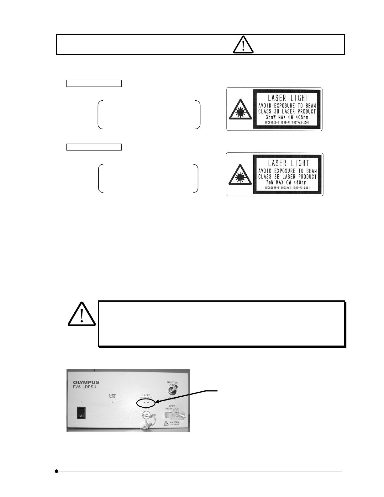
When red LED’s of LASER EMISSION on FV5-LDPSU are lighting, it indicates that laser is
being emitted. When microscope is connected, the laser is emitted from objective tip.
Reflection may enter your eyes or light may be scattered around. Care must be taken in this
case. In addition, do not see the sample while laser is scanning.
When two red LED’s are
lighting, it means “laser
emission”.
Page
I.
SAFETY GUIDE
I .
1-1
Page 12

Safety Considerations
Regarding settings of DIP switches located at back panel of FV5-LDPSU, refer to VI 1 –
Back panel switch settings.
z Set this system on robust base.
z This system generates heat. When installing this system, make it sure that a space of 10cm or more is
provided, left and right of the system, and do not block vent openings.
z Power cable may be molten when it hits hot place of lamp housing. When installing, make it sure that the
power cable is adequately apart from the lamp housing.
z Never insert a metal piece into vent opening as it may cause failure or electric shock.
z Do not apply your hand or finger to laser beam that comes from mounting hole of objective lens or objective
tip.
If your hand or finger is exposed to laser beam, it may cause a skin hazard. In addition, never insert a
mirror into light path as the laser beam may come outside and it may enter your eye which is very
dangerous
z Do not set or remove the sample during laser emission (laser scanning). If you set or remove the sample
in such a case, reflection from the sample may enter your eye which is very dangerous. Moreover, do not
look at the sample during laser emission (laser scanning).
z System performance as well as system safety cannot be guaranteed in case that cover is detached or the
system is disassembled with use of tools. Never disassemble the system.
z Do not bend or pull fiber excessively. Do not step on the fiber. If the fiber is broken, laser beam may leak
which is very dangerous. In case that such unlikely event occurred, turn power of laser power supply unit
to OFF position immediately and contact our sales office. (when using FV5-LD405 only)
z Always use the power cord provided by Olympus. If no power cord is provided, please select the proper
power cord by referring to the section “PROPER SELECTION OF THE POWER SUPPLY CORD ”at the
end of this instruction manual.
I
. SAFETY GUIDE
I .
1-2
Page
Page 13

Safety Considerations
z Connect the power cord correctly and ensure that the ground terminal of the power supply and that of the
wall outlet are properly connected. If the equipment is not grounded, Olympus can no longer warrant the
electrical safety and performance of the equipment.
z Before connecting cord and cable, verify that the main switch is turned to O – (OFF) position.
z Mixture (alcohol (3): ether (7)) that is used for cleaning optics is high inflammable so that utmost care must
be taken when handling with respect to fire and main switch ON/OFF. When using ether, it is
recommended that the room is well-ventilated.
z Be careful so as not to apply any excessive force to connecting cord or cable as it is very weak against
bend or twist.
z Do not change fuses that are located above the power cord connector. When change of fuses is required,
contact and consult with our local sales office.
z Do not carry the semiconductor laser head by hand. It may be damaged as it is very delicate tool.
z Do not swing around fiber carelessly. If fiber being emitted is swung around, laser beam may hit human
body that would cause a hazard. (when using FV5-LD405 ONLY)
z When you dispose of this system, it is necessary to handle it as an industrial waste. In case that you
cannot dispose it yourself, deliver it to our local sales office.
Page
I.
SAFETY GUIDE
I .
1-3
Page 14
Safety Considerations
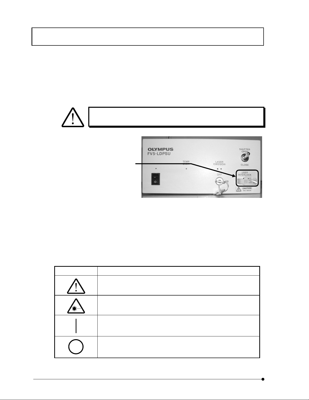
z External remote control connector is provided.
(Rating of external remote interlock circuit: Rated current 0.3A, Rated voltage 5V)
When shipping, a short pin of interlock connector is provided. Instead of the short pin, the external remote
interlock circuit can be connected. For further details, see Chapter 4 - USER’S SAFETY PROTECTION
MEASURES ACCORDING TO IEC60825-1:1993+A1:1997+A2:2001 “LASER PRODUCT RADIATION
SAFETY STANDARD”.
When using remote interlock connector, contact our local sales office for sure
as it may cause electric shock or fire.
Remote interlock
connector of this system
z See also instruction manual for microscope regarding safety considerations.
Symbols related to safety
This system is attached with the following marks.
Understand the meaning of symbols and handle the system safely.
Symbol Meaning
Before using, read instruction manual for sure.
In case of error handling, user may get hazard or products may be damaged.
Laser beam is used. Pay utmost care to handling.
Main switch is turned ON.
Main switch is turned OFF.
I
. SAFETY GUIDE
I .
1-4
Page
Page 15
Warning label / Label related to laser safety
2 Warning label
2-1 Label related to laser safety
Warning is displayed at the place where a care must be paid in handling and operating the system. Exercise
the instruction for sure. When label is blurred or peeled off, contact our local sales office and ask if new label for
change is available.
2-1-1 Warning label
The warning label shown below is attached to the system.
(In case of FV5-LD405) (In case of FV5-LD440)
Place attached
(In case of FV5-LD405) (In case of FV5-LD440)
Warning label is attached.
In case that you purchase our FV5-FUR405,
our service personnel would attach
manipulator cover to it.
Page
I.
SAFETY GUIDE
I .
2-1
Page 16
Warning label / Label related to laser safety
A
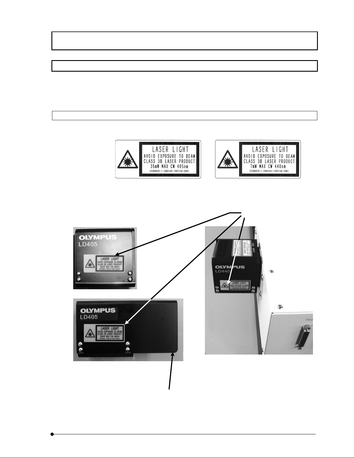
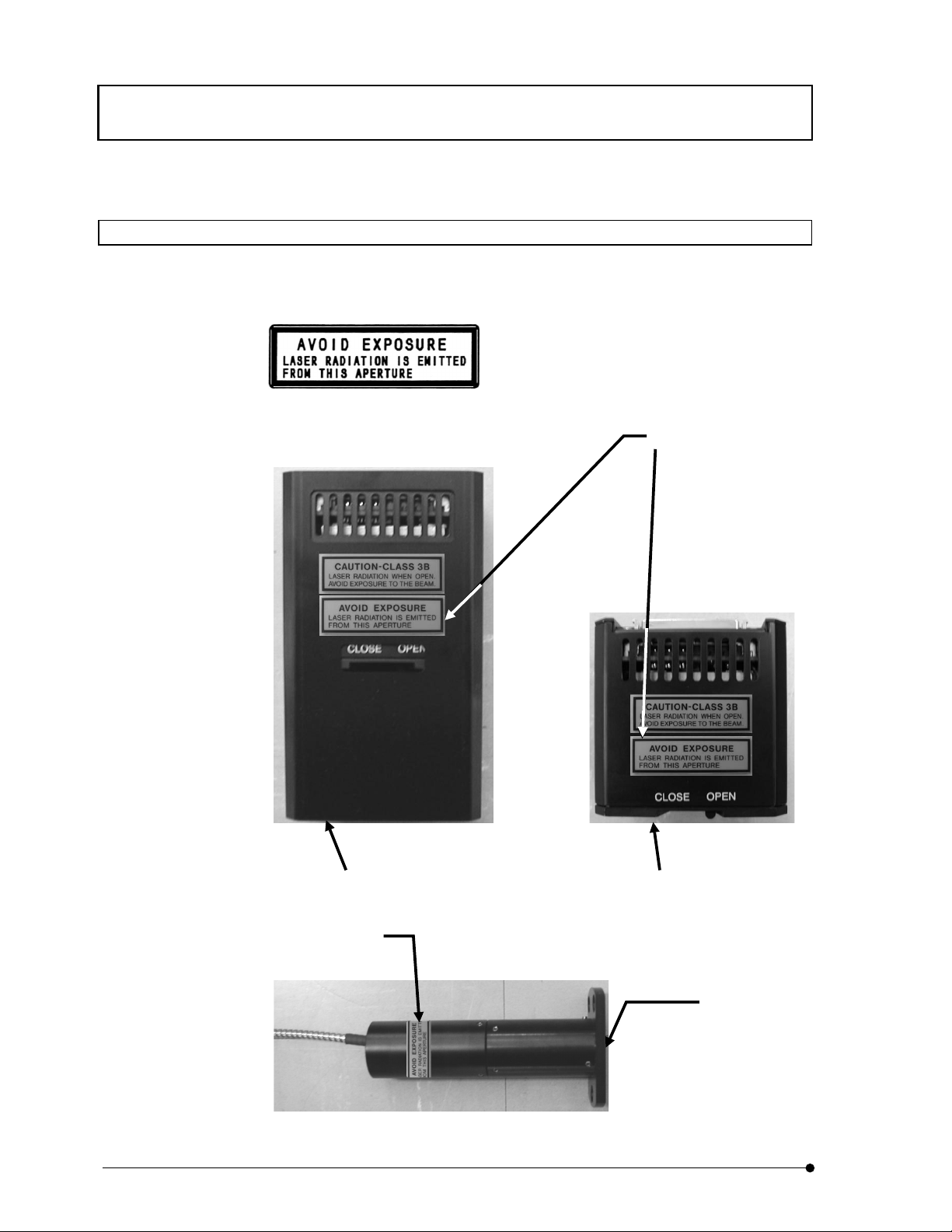
2-1-2 Aperture label
Aperture label shown below is attached to the system.
Place attached
In case that you purchase our FV5FUR405, our service personnel would
attach manipulator cover to it.
perture label is attached.
(In case of FV5-LD405)
The case where the shutter is
open and the fiber cable
disconnected.
Aperture label is attached.
Laser beam comes out here.
(In case of FV5-LD405)
I.
SAFETY GUIDE
I .
2-2
Page
Page 17
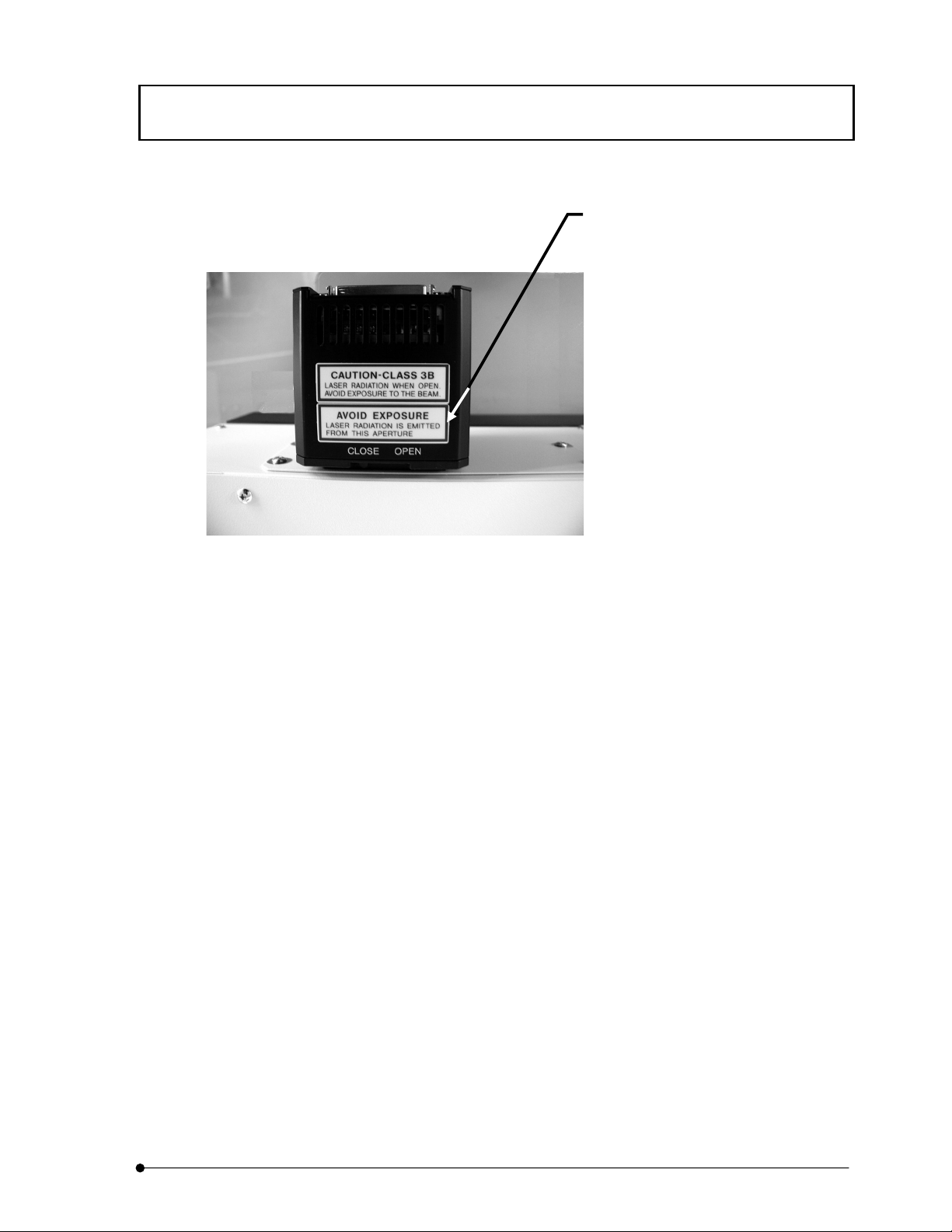
Warning label / Label related to laser safety
Opening label is attached.
(In case of FV5-LD440)
Page
I.
SAFETY GUIDE
I .
2-3
Page 18
Warning label / Label related to laser safety
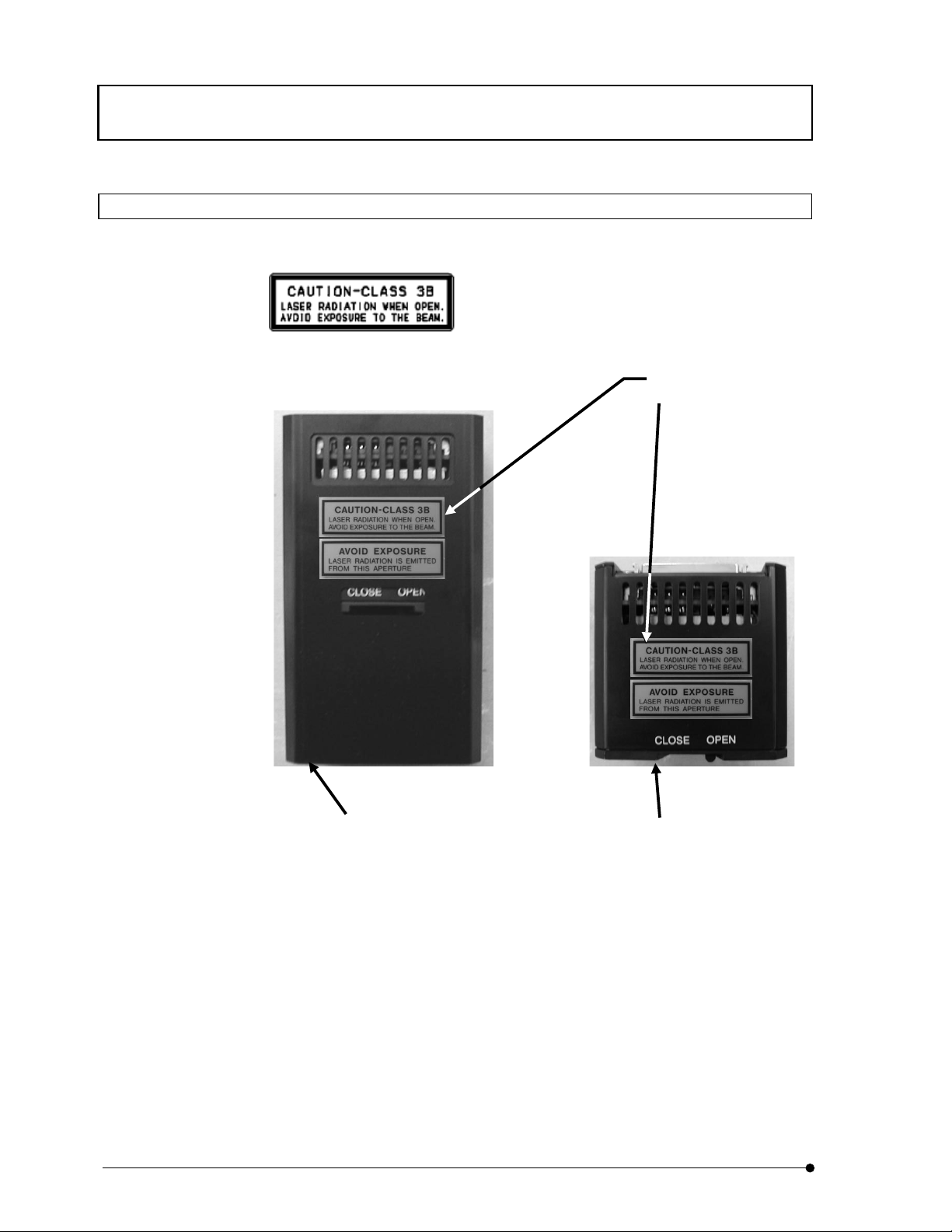
2-1-3 Protective housing label
Protective housing label as shown below is attached to the system.
Place attached
In case that you purchase our FV5-FUR405,
our service personnel would attach
manipulator cover to it.
Protective housing label is
attached.
(In case of FV5-LD405)
The case where the shutter is
open and the fiber cable
disconnected.
I.
SAFETY GUIDE
I .
2-4
Page
Page 19
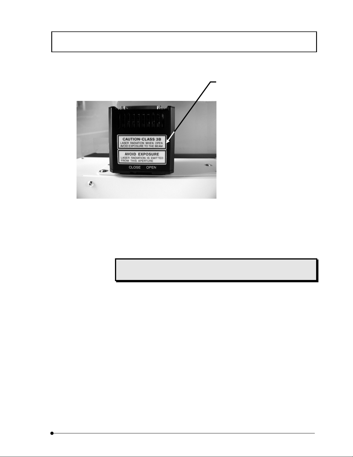
Warning label / Label related to laser safety
Protective housing label is
attached.
(In case of FV5-LD440)
Protective housing label may be attached to the place other than the place shown in this
manual. It is a warning label for our service personnel.
When label is blurred or peeled off, contact our local sales office for availability of label
for change.
Page
I.
SAFETY GUIDE
I .
2-5
Page 20

Page 21

Cautions when using the system
3 Cautions when using the system
3-1 About system move
z Assembling and setup of this system are executed by our service parsonnel. Avoid move of the system as
it may put optics system out of order. When the move of this system is required, contact and consult with
our local sales office. In an event of disorder or breakage of the system due to the move by customer, we
hold no responsibility.
3-2 Caution when using
z Handle this system with utmost care in order not to give a shock as it is precision instrument.
z Do not bend, pull or step on fiber excessively. Performance would severely be deteriorated. (when using
FV5-LD405 only).
z Power cable is also used to stop power supply against unlikely event. Power cable connector (located at
back panel of FV5-LDPSU) or power consent should be within a reach of your hand. Set the power supply
unit at the place where you can remove power cable easily against unlikely event. However, do not
remove it during power supply except emergency situation.
z Do not move the system by pulling power cable.
z For environment condition of usage, see II Chapter 2 – Specifications.
z When you clean each section, use soft cloth that contains diluted mild detergent and wipe out gently. Do
not use organic solvent as it would deteriorate paint or plastic parts.
3-3 Caution
Safety may not be guaranteed if the system is used by other methods than those described in this manual and
failure may occur. Use this system in accordance with this manual.
Page
I.
SAFETY GUIDE
I .
3-1
Page 22

Page 23

USER’S SAFETY PROTECTION MEASURES ACCORDING TO IEC60825-
1:1993+A1:1997+A2:2001 “LASER PRODUCT RADIATION SAFETY STANDARD”
4 USER’S SAFETY PROTECTION
MEASURES ACCORDING TO
IEC60825-1:1993+A1:1997+A2:2001
“LASER PRODUCT RADIATION
SAFETY STANDARD”
IEC60825-1:1993+A1:1997+A2:2001 requires the users of laser products to take proper safety protection measures
(summarized below). When using this system, be sure to take proper measures regarding the following points.
For details, please refer to the IEC60825-1:1993+A1:1997+A2:2001 mentioned above.
For warning labels used with this system and their positions, see Section 2, “Warning Labels” of this manual.
This requirement does not apply to Class 3B laser products with not more than five times the AEL of Class 2 in
the wavelength range from 400 nm to 700 nm.
Page
I.
SAFETY GUIDE
I .
4-1
Page 24

USER’S SAFETY PROTECTION MEASURES ACCORDING TO IEC608251:1993+A1:1997+A2:2001 “LASER PRODUCT RADIATION SAFETY STANDARD”
NOTE 1 There is only limited evidence about effects for exposures of less than 10-9s for wavelengths less
than 400 nm and greater than 1400 nm. The AELs for these exposure times and wav
derived by calculating the equivalent radiant power or irradiance from the radiant
-9
applying at 10
NOTE 2 Correction factors C
s for wavelengths less than 400 nm and greater than 1400 nm.
to C7 and breakpoints T1 and T2 used in tables 1 to 4 are defined in the
1
following expressions and are illustrated in figures 1 to 8.
Parameter Spectral region Figures
C1 = 5,6 x 10³t
T1 = 10
0,8(nj-295)
C2 = 10
T2 = 10 x 10
0,25
-15
x 10
0,2(nj-265)
[(ǂ –ǂmin)/98,5]sa
s 302,5 to 315 2
302,5 to 400 1
302,5 to 315 3
400 to 1400 4
C3 = 1,0 400 to 450 5
C3 = 10
C4 = 10
0,02(nj-450)
0,002(nj-700)
450 to 600 5
700 to 1050 6
C4 = 5 1050 to 1400 6
C6 = ǂ/ǂ
C6 = ǂ
C5 = 10
C6 = 1 for ǂ ǂ
for ǂ
min
max/ǂmin
min
= 66,7 for ǂ > ǂ
-1/4 b
min
< ǂ ǂ
max
min
400 to 10
400 to 1400
400 to 1400
d
400 to 1400
6
C7 = 1 700 to 1150 8
C7 = 10
0,018(nj-1150)
1150 to 1200 8
C7 = 8 1200 to 1400 8
a
T2= 10 s for ǂ < 1,5 mrad and T2 = 100 s for ǂ > 100 mrad
b
C5 is only applicable o pulse durations shorter than 0,25 s.
c
C6 is only applicable to pulsed lasers and to CW lasers where thermal injury dominates (see table 1)
d
The limiting angle of acceptance p shall be equal to ǂ
ǂ
min = 1,5 mrad
ǂ
max = 100 mrad
N
is the number of pulses contained within the applicable duration (see 8.4f) and 13.3)
max
elengths have been
power or radiant exposure
7
c
c
c
NOTE 3 See table 7 for limiting apertures.
NOTE 4 In the formulae in the tables 1 to 4 and in these no
t
nanometres, the emission duration
I.
SAFETY GUIDE
I .
4-2
Page
has to be expressed in seconds and ǂ has to be expressed in milliradians.
tes, the wavelength has to be expressed in
Page 25

USER’S SAFETY PROTECTION MEASURES ACCORDING TO IEC60825-
1:1993+A1:1997+A2:2001 “LASER PRODUCT RADIATION SAFETY STANDARD”
10
10.1
This section specifies safety precautions and control measures to be taken by the user of a laser product, in
accordance with its hazard classification. Often users can use the manufacturer's classification of the product
for classification of the laser installation, thus avoiding all measurements. This section is supplied for the
user's information. Nothing in this section shall be considered as constraints or requirements imposed upon the
manufacturer. For installations where Class 3R laser products emitting energy outside of the 400nm to 700nm
wavelength range or Class 3B or Class 4 laser products are operated, a laser safety officer should be appointed.
It should be the laser safety officer’s responsibility to review the following precautions and designate the
appropriate controls to be implemented. If should be the laser safety officer's responsibility to review the
following precautions and designate the appropriate controls to be implemented. Wherever practicable, laser
protective enclosures should be used for lasers of Class 3B or Class 4. Warning labels should be placed upon
removable parts of protective enclosures or at service connections where a hazard is introduced by their
removal or by disconnection.
Safety precautions
General
The purpose of safety precautions and control measures is to reduce the possibility of exposure to hazardous
levels of laser radiation, and to other associated hazards. Therefore, it may not be necessary to implement all of
the control measures given. Whenever the application of any one or more control measures reduces the possible
exposure to a level at or below the applicable MPE, then the application of additional control measures should
not be necessary.
If a user modification of a previously classified laser product affects any aspect of the product's performance or
intended functions within the scope of this standard, the person or organization performing any such
modification is responsible for ensuring the reclassification and relabelling of the laser product.
I.
SAFETY GUIDE
Page
I .
4-3
Page 26

USER’S SAFETY PROTECTION MEASURES ACCORDING TO IEC608251:1993+A1:1997+A2:2001 “LASER PRODUCT RADIATION SAFETY STANDARD”
10.2
The remote interlock connector of Class 3B and Class 4 lasers should be connected to an emergency master
disconnect interlock or to room, door or fixture interlocks (see 4.4).
The person in charge may be permitted momentary override of the remote interlock connector to allow access to
other authorized persons if it is clearly evident that there is no optical radiation hazard at the time and point of
entry.
10.3
Class 3B and Class 4 laser products not in use should be protected against unauthorized use by removal of the
key from the key control (see 4.5).
10.4
Use of remote interlock connector
Key control
Beam stop or attenuator
The inadvertent exposure of bystanders to laser radiation from Class 3B or Class 4 laser products should be
prevented by the use of the beam attenuator or beam stop (see 4.7).
10.5
The entrances to areas or protective enclosures containing Class 3B and Class 4 laser products should be
posted with appropriate warning signs.
I.
SAFETY GUIDE
Warning signs
I .
4-4
Page
Page 27

USER’S SAFETY PROTECTION MEASURES ACCORDING TO IEC60825-
1:1993+A1:1997+A2:2001 “LASER PRODUCT RADIATION SAFETY STANDARD”
10.6
The beam emitted by each Class 1M and Class 2M laser product classified under condition 1 of table 10, each
Class 3R laser product emitting energy outside of the 400nm to 700nm wavelength range, and each Class 3B or
Class 4 laser product should be terminated at the end of its useful path by a diffusely reflecting material of
appropriate reflectivity and thermal properties or by absorbers.
Open laser beam paths should be located above or below eye level where practicable.
The beam paths of Class 3R laser products emitting energy outside of the 400nm to 700nm wavelength range
and Class 3B or 4 laser products should be as short as practicable, should have a minimum number of
directional changes, should avoid crossing walkways and other access routes, and should, where practicable, be
enclosed. The beam enclosure (for example, a tube) should be securely mounted but preferably not rigidly
attached to (or provide support for) beam-forming components.
Beam paths
Page
I.
SAFETY GUIDE
I .
4-5
Page 28

USER’S SAFETY PROTECTION MEASURES ACCORDING TO IEC608251:1993+A1:1997+A2:2001 “LASER PRODUCT RADIATION SAFETY STANDARD”
10.7
Care should be exercised to prevent the unintentional specular reflection of radiation from Class 3R, Class 3B
or Class 4 laser products. Mirrors, lenses and beam splitters should be rigidly mounted and should be subject to
only controlled movements while the laser is emitting.
Care should be exercised to prevent the unintentional specular reflection of radiation from Class 1M and Class
2M laser products from surfaces that may focus the beam.
Reflecting surfaces that appear to be diffuse may actually reflect a considerable part of the radiation beam
specularly, especially in the infra-red spectral range. This may be potentially hazardous for longer distances
than one would expect for purely (Lambertian) diffuse reflections.
Special care needs to be taken in the selection of optical components for Class 3B and Class 4 lasers and in
maintaining the cleanliness of their surfaces.
Potentially hazardous specular reflections occur at all surfaces of transmissive optical components such as
Specular reflections
lenses, prisms, windows and beam splitters.
Potentially hazardous radiation can also be transmitted through some reflective optical components such as
mirrors (for example, infra-red radiation passing through a reflector of visible radiation).
I.
SAFETY GUIDE
I .
4-6
Page
Page 29

USER’S SAFETY PROTECTION MEASURES ACCORDING TO IEC60825-
1:1993+A1:1997+A2:2001 “LASER PRODUCT RADIATION SAFETY STANDARD”
10.8
Eye protection which is designed to provide adequate protection against specific laser wavelengths should be
used in all hazard areas where Class 3R laser products emitting energy outside of the 400 nm to 700 nm
wavelength range, Class 3B or Class 4 lasers are in use (see clause 12). Exceptions to this are
Eye protection
a) when engineering and administrative controls are such as to eliminate potential exposure in excess of
the applicable MPE;
b) when, due to the unusual operating requirements, the use of eye protection is not practicable. Such
operating procedures should only be undertaken with the approval of the laser safety officer.
c) maximum permissible exposure (MPE);
d) optical density of eyewear at laser output wavelength;
e) visible light transmission requirements;
f) radiant exposure or irradiance at which damage to eyewear occurs;
g) need for prescription glasses;
h) comfort and ventilation;
i) degradation or modification of absorbing media, even if temporary or transient;
j) strength of materials (resistance to shock);
k) peripheral vision requirements;
l) any relevant national regulations.
Eye protection which is designed to provide adequate protection against specific laser radiations should be
used in all hazard areas where Class 3B or Class 4 lasers are in use (see clause 12). This requirement does not
apply to Class 3B laser products with not more than five times the AEL of Class 2 in the wavelength range
from 400 nm to 700 nm. Additional exceptions to this are:
a) when engineering and administrative controls are such as to eliminate potential exposure in excess of the
applicable MPE;
b) when, due to the unusual operating requirements, the use of eye protection is not practicable. Such
operating procedures should only be undertaken with the approval of the laser safety officer.
I.
SAFETY GUIDE
Page
I .
4-7
Page 30

USER’S SAFETY PROTECTION MEASURES ACCORDING TO IEC608251:1993+A1:1997+A2:2001 “LASER PRODUCT RADIATION SAFETY STANDARD”
10.8.1
All laser protective eyewear shall be clearly labelled with information adequate to ensure the proper choice of
eyewear with particular lasers.
10.8.2
The spectral optical density
protective eyewear is required to cover a band of radiation, the minimum value of
band shall be quoted. The value of
where
10.8.3
Special attention has to be given to the resistance and stability against laser radiation when choosing eyewear
Identification of eyewear
Required optical density
of laser protective eyewear is normally highly wavelength dependent Where
D
O
required to give eye protection can be calculated from the formula:
D
O
D
O
is the expected unprotected eye exposure level.
H
0
Protective eyewear
measured within the
D
O
H
10
0
MPE
log
for protection against Class 4 lasers.
10.9
Special attention has to be given to the resistance and stability against laser radiation when choosing clothing
for protection against Class 4 lasers.
I.
SAFETY GUIDE
Protective clothing
I .
4-8
Page
Page 31

USER’S SAFETY PROTECTION MEASURES ACCORDING TO IEC60825-
1:1993+A1:1997+A2:2001 “LASER PRODUCT RADIATION SAFETY STANDARD”
10.10
Operation of Class 1M and Class 2M laser products that failed condition 1 of table 10, Class 3R, Class 3B and
Class 4 laser systems can represent a hazard not only to the user but also to other people over a considerable
distance.
Because of this hazard potential, only persons who have received training to an appropriate level should be
placed in control of such systems. The training, which may be given by the manufacturer or supplier of the
system, the laser safety officer, or by an approved external organization, should include, but is not limited to:
Training
a) familiarization with system operating procedures;
b) the proper use of hazard control procedures, warning signs, etc.;
c) the need for personal protection;
d) accident reporting procedures;
e) bioeffects of the laser upon the eye and the skin.
See also clause 12.
I.
SAFETY GUIDE
Page
I .
4-9
Page 32

USER’S SAFETY PROTECTION MEASURES ACCORDING TO IEC608251:1993+A1:1997+A2:2001 “LASER PRODUCT RADIATION SAFETY STANDARD”
10.11
In the absence of national regulations, the following recommendations should be taken into consideration:
11
Depending on the type of laser used, associated hazards involved in laser operations may include the following:
Medical supervision
a) the value of medical surveillance of laser workers is a fundamental problem as yet unresolved by the
medical profession. If ophthalmic examinations are undertaken, they should be carried out by a
qualified specialist and should be confined to workers using Class 3B and Class 4 lasers;
b) a medical examination by a qualified specialist should be carried out immediately after an apparent or
suspected injurious ocular exposure. Such an examination should be supplemented with a full
biophysical investigation of the circumstances under which the accident occurred;
c) pre, interim, and post employment ophthalmic examinations of workers using Class 3B and Class 4
lasers have value for medical legal reasons only and are not a necessary part of a safety program.
Hazards incidental to laser operation
11.1
I.
SAFETY GUIDE
I .
4-10
Atmospheric contamination
a) Vapourized target material and reaction products from laser cutting, drilling, and welding operations.
These materials may well include asbestos, carbon monoxide, carbon dioxide, ozone, lead, mercury, other
metals, and biological material.
b) Gases from the flowing gas laser systems or from the by products of laser reactions, such as bromine,
chlorine, and hydrogen cyanide.
c) Gases or vapours from cryogenic coolants.
d) Gases used to assist laser-target interactions, such as oxygen.
Page
Page 33

USER’S SAFETY PROTECTION MEASURES ACCORDING TO IEC60825-
1:1993+A1:1997+A2:2001 “LASER PRODUCT RADIATION SAFETY STANDARD”
11.2
11.2.1
There may be a considerable hazard from the ultra-violet radiation associated with flashlamps and CW laser
discharge tubes, especially when ultra-violet transmitting tubing or mirrors (such as quartz) are used.
11.2.2
The visible and near infra-red radiation emitted from flash tubes and pump sources and target re-radiation
may be of sufficient radiance to produce potential hazard.
11.3
Most lasers make use of high voltages (>1 kV) and pulsed lasers are especially dangerous because of the stored
energy in the capacitor banks.
Collateral radiation hazards
Ultra-violet collateral radiation
Visible and intra-red collateral radiation
Electrical hazards
Unless properly shielded, circuit components such as electronic tubes working at anode voltages greater than 5
kV may emit X-rays.
I.
SAFETY GUIDE
Page
I .
4-11
Page 34

USER’S SAFETY PROTECTION MEASURES ACCORDING TO IEC608251:1993+A1:1997+A2:2001 “LASER PRODUCT RADIATION SAFETY STANDARD”
11.4
Cryogenic liquids may cause burns and require special handling precautions.
11.5
Specifications for laser products used to process materials may vary according to their Intended use. If the user
wishes to process materials other than those recommended by the manufacturers, he should make himself
aware of the different degrees of risk and hazards associated with the processing of such materials, and take
appropriate precautions to prevent, for example, the emission of toxic fume, fire, explosion or reflection of laser
radiation from the workpiece.
11.6
The potential for explosions at the capacitor bank or optical pump systems exists during the operation of some
Cryogenic coolants
Materials processing
Other hazards
high-power laser systems. There is a possibility of flying particles from the target area in the laser cutting,
drilling, and welding operations. Explosive reactions of chemical laser reagents or other gases used within the
laboratory are also possible.
I.
SAFETY GUIDE
I .
4-12
Page
Page 35

USER’S SAFETY PROTECTION MEASURES ACCORDING TO IEC60825-
1:1993+A1:1997+A2:2001 “LASER PRODUCT RADIATION SAFETY STANDARD”
12
12.1
Three aspects of the use of lasers need to be taken into account in the evaluation of the possible hazards and in
the application of control measures:
The practical means for evaluation and control of laser radiation hazards is to classify laser systems according
to their relative hazard potential, and then to specify appropriate controls for each class. The use of the
classification system will in most cases preclude any requirement for radiometric measurements by the user.
The classification scheme relates specifically to the accessible emission from the laser system and the potential
Procedures for hazard control
General
a) the capability of the laser or laser system to injure personnel. This includes any consideration of human
access to the main exit port or any subsidiary port;
b) the environment in which the laser is used;
c) the level of training of the personnel who operate the laser or who may be exposed to its radiation.
hazard based on its physical characteristics. However, environmental and personnel factors are also relevant
in determining the control measures required and a responsible person should be designated as laser safety
officer, to be responsible for providing informed judgments on situations not specifically covered by this
standard.
The following details relate to safe operation of laser products in:
– outdoor and construction environments where administrative controls often provide the only reasonable
approach to safe operation;
– laboratory and workshop environments where engineering controls may play the greatest role;
– display and demonstration environments, where pre-planning, delineation and control of access often
provide the only reasonably practicable approach to safe operation.
I.
SAFETY GUIDE
Page
I .
4-13
Page 36

USER’S SAFETY PROTECTION MEASURES ACCORDING TO IEC608251:1993+A1:1997+A2:2001 “LASER PRODUCT RADIATION SAFETY STANDARD”
12.2
The hazard potential for Class 3B and Class 4 lasers may extend over a considerable distance. The range from
the laser at which the irradiance or radiant exposure falls below the appropriate MPE is termed the nominal
ocular hazard distance (NOHD). The area within which the beam irradiance or radiant exposure exceeds the
appropriate MPE is called the nominal ocular hazard area (NOHA). This area is bounded by the limits of
traverse, elevation and pointing accuracy of the laser system and extends either to the limit of the NOHD or to
the position of any target or backstop. The exact NOHA will also depend on the nature of any material within
the beam path, e.g., specular reflectors.
The NOHD is dependent on the output characteristics of the laser, the appropriate MPE, the type of optical
system used, and the effect of the atmosphere on beam propagation. Formulae and examples for calculating the
NOHD are given in annex A.
12.3
Hazard evaluation for Class 3B and Class4 lasers used outdoors
Personal protection
The need to use personal protection against the hazardous effects of laser operation should be kept to a
minimum by administrative controls, engineering design and by beam enclosure.
When personnel may be exposed to potentially hazardous laser radiation (Class 3B and Class 4) adequate
personal protection should be provided.
I.
SAFETY GUIDE
I .
4-14
Page
Page 37

USER’S SAFETY PROTECTION MEASURES ACCORDING TO IEC60825-
1:1993+A1:1997+A2:2001 “LASER PRODUCT RADIATION SAFETY STANDARD”
12.4
Only Class 1 or Class 2 laser products should be used for demonstration, display or entertainment in
unsupervised areas. The use of other classes of lasers for such purposes should be permitted only when the
laser operation is under the control of an experienced, well-trained operator and/or when spectators are
prevented from exposure to levels exceeding the applicable MPE.
Each demonstration laser product used for educational purposes in schools, etc. should comply with all of the
applicable requirements for a Class 1 or Class 2 laser product. A demonstration laser product shall not permit
human access to laser radiation in excess of the accessible emission limits of Class 1 or Class 2 as applicable.
NOTE – Additional guidance can be found in IEC 60825-3, a technical report on the safety p
laser light shows and displays.
12.5
Laser demonstrations, displays and exhibitions
recautions for
Laboratory and workshop laser installations
12.5.1
Precautions are only required to prevent continuous viewing of the direct beam; for Class 1M, Class 2 and
Class 2M, a momentary (0,25 s) exposure to radiation in the wavelength range400 nm to 700nm as would occur
in accidental viewing situations is not considered hazardous. However, the laser beam should not be
intentionally aimed at people. The use of optical viewing aids (for example, binoculars) with Class 1M, Class
2M and Class 3R laser products may Increase the ocular hazard. Additional precautions for Class 1M, Class
2M and Class 3R laser products are given in 12.6.2.
Class 1M, Class 2, Class 2M and Class 3R laser products
I.
SAFETY GUIDE
Page
I .
4-15
Page 38

USER’S SAFETY PROTECTION MEASURES ACCORDING TO IEC608251:1993+A1:1997+A2:2001 “LASER PRODUCT RADIATION SAFETY STANDARD”
12.5.2
Class 3B lasers are potentially hazardous if a direct beam or specular reflection is viewed by the unprotected
eye (intrabeam viewing). The following precautions should be taken to avoid direct beam viewing and to control
specular reflections.
Class 3B laser products
a) The laser should only be operated in a controlled area.
b) Care should be exercised to prevent unintentional specular reflections.
c) The laser beam should be terminated where possible at the end of its useful path by a material that is
diffuse and of such a colour and reflectivity as to make beam positioning possible while still minimizing
the reflection hazards.
NOTE - Conditions for safe viewing of diffuse reflections for Class 3B visible laser: are: mini
distance of 13 cm between screen and cornea and a maximum viewing time of 10 s. Other view
conditions require a comparison of the diffuse reflection exposure with the MPE.
mum viewing
ing
d) Eye protection is required if there is any possibility of viewing either the direct or specularly reflected
beam, or of viewing a diffuse reflection not complying with the conditions of item c).
e) The entrances to areas should be posted with a standard laser warning sign.
I.
SAFETY GUIDE
I .
4-16
Page
Page 39

USER’S SAFETY PROTECTION MEASURES ACCORDING TO IEC60825-
P
1:1993+A1:1997+A2:2001 “LASER PRODUCT RADIATION SAFETY STANDARD”
12.5.3
Class 4 laser products can cause injury from either the direct beam or its specular reflections and from diffuse
reflections. They also present a potential fire hazard. The following controls should be employed in addition to
those of 12.5.2 to minimize these risks.
Class 4 laser products
a) Beam paths should be enclosed whenever practicable. Access to the laser environment during laser
operation should be limited to persons wearing proper laser protective eyewear and protective clothing.
Beam paths should avoid work area where possible, and long sections of tubes should be mounted so that
thermal expansion, vibration, and other sources of movements in them do not significantly affect the
alignment of beam forming components.
b) Class 4 lasers should be operated by remote control whenever practicable, thus eliminating the need far
personnel to be physically present in the laser environment.
c) Good room illumination is important in areas where laser eye protection is worn. Light-coloured diffuse
wall surfaces help to achieve this condition.
d) Fire, thermally Induced aberrations in optical components and the melting or vapourization of solid
targets designed to contain the laser beam, are all potential hazards induced by the radiation from
Class 4 lasers. A suitable beam stop should be provided, preferably in the form of an adequately cooled
metal or graphite target. Very high power densities can be handled by absorbing the radiation over
several reflections, each reflecting surface being inclined at such an angle to the incident radiation as to
spread the laser power over a wide area.
e) Special precautions may be required to prevent unwanted reflections in the invisible spectrum from far
infra-red laser radiation and the beam and target area should be surrounded by a material opaque at
the laser wavelength. (Even dull metal surfaces may become highly specular at the CO2 wavelength of
10,5
Local screening should be used wherever practicable to reduce the extent of reflected radiation.
The alignment of optical components in the path of a Class 4 laser beam should be initially and periodically
checked.
m
).
I.
SAFETY GUIDE
Page
I .
4-17
Page 40

Page 41

.
IIII.
S
S
Y
S
T
E
Y
S
T
This section describes outline and specifications of this
system.
M
E
M
S
P
S
P
Note for this section
O
O
E
E
U
U
C..
C
T
T
LII
L
N
N
E
E
&
&
We recommend that you use this system after reading this
section and understanding this system.
Page 42

Page 43

CONTENTS
1 System Outline 1-1
1-1 System Outline................................................................................. 1-1
2 Specifications 2-1
2-1 Specifications of this system ......................................................... 2-1
3 Operating hours 3-1
3-1 Hour meter........................................................................................ 3-1
Regarding DIP switches at back panel of FV5-LDPSU, see VI – 1
[Warning to back panel switch settings].
Page 44

Page 45

1 System Outline
1-1 System Outline
1. This is a semiconductor laser diode system (LD) designed as compact, low-power
consumption and very quiet system.
2. LD itself is of temperature constant type so that the system can suppress
fluctuation of wavelength and power.
3. Light-stable laser output can be acquired with light feedback.
4. This system can attain the function equivalent to AOTF even if connected confocal
microscope does not have the function. (FV5-LD405 only)
System Outline
TIP
5. Image can be acquired in various methods by integrating our FV300, FV500 and
FV1000.
For further details of AOTF and ROI / REX function, see manual for
FV300, FV500 and FV1000.
II .
SYSTEM OUTLINE & SPEC.
Page
II .
1-1
Page 46

Page 47

2 Specifications
2-1 Specifications of this system
Unit Specifications
Semiconductor laser head
Specifications
FV5-LD405 Output
Wavelength
Dimensions(mm)
Mass
FV5-LD440 Output
Wavelength
Dimensions(mm)
Mass
Semiconductor laser
power supply unit
FV5-LDPSU
FV5-LDPSU(Type2) Mass 2,700g
Fiber cable Kind Polarized preserved fiber cable
FV5-FUR405 Fiber output
Environment conditions • Indoor use
Rating
Dimensions(mm)
Length
Max: 25mW
Min: 400nm Max: 408nm Typ: 405nm
70(W)×127(D)×70(H) (With a manipulator cover)
70(W)×70(D)×70(H) (Without a manipulator cover)
500g
Max: 5mW
Min: 437nm Max: 443nm Typ: 440nm
70(W)×70(D)×70(H)
500g
100-120/200-240V~
0.4/0.25A 50/60Hz
210(W)×300(D)×100(H)
Min: 6mW Max: 13mW (when integrated with FV5-LD405)
3m
• Altitude up to 2000m
• Temperature 10°C~35°C(FV300 and FV500)
18°C~28°C(FV1000)
• Humidity 30%~80% (up to 31°C)
Humidity at environment of 31°C or more will go down
linearly and become 70% at 34°C.
• Power voltage fluctuation: ±10%
• Pollution degree 2 (IEC60664)
• Installation category (Over voltage category) II
(IEC60664)
Storage environment • Temperature -25°C~65°C
• Humidity 10%~90%
This device complies with the requirements of both directive 89/336/EEC concerning electromagnetic
compatibility and directive 73/23/EEC concerning low voltage. The CE marking indicates compliance with the
above directives.
II.
SYSTEM OUTLINE & SPEC.
II.
Page
2-1
Page 48

Page 49

3 Operating hours
Operating hours of this system is described.
3-1 Hour meter
Hour meter is attached at back panel of FV5-LDPSU.
Hour meter indicates total time that the laser is being lighted.
Operating hours
NOTE
TIP
The reset switch on the Hour meter panel is not be refreshed, even if it is pushed.
Hour meter
HOUR METER INDICATES THE TIME IN SEVEN DIGITS AS FOLLOWS.
HHHHMM.M
MM.M (LOWER 3 DIGITS): MINUTE IS DISPLAYED IN RANGE OF 0.00 a 59.9.
HHHH (UPPER 4 DIGITS): HOUR IS DISPLAYED IN RANGE OF 0 a 9999.
E.G.: IN CASE THAT 142123.3 IS DISPLAYED, IT INDICATES THAT THE LASER
WAS LIGHTED FOR A TOTAL OF 1421 HOURS 23.3 MINUTES.
II.
SYSTEM OUTLINE & SPEC.
II.
Page
3-1
Page 50

Page 51

IIIIII.
.
P
A
C
P
A
This section describes packing details of this system.
We recommend that you use this system after reading this
section and checking the details of packing.
C
KII
K
C
C
N
G
N
G
H
E
H
E
Note for this section
C
C
D
D
K
K
E
E
T
T
AII
A
L
L
S
S
Page 52

Page 53

CONTENTS
1 Integration with this system 1-1
1-1 ND Combiner (FV5-COMB(2)) configuration for FV300 or FV500
with this system ..............................................................................1-1
1-2 AOTF Combiner (FV5-COMBA) configuration for FV300 or FV500
with this system ..............................................................................1-1
1-3 ND Combiner (FV5-COMB2) of FV300 / FV500 configuration with
FV5-LD440........................................................................................1-2
1-4 LD Interface(FV10-LDIF) configuration for LD405 laser or LD440
laser in FV1000 system................................................................... 1-2
1-4-1 LD405 configuration ...................................................................................... 1-2
1-4-2 LD440 Configuration .....................................................................................1-2
2 Packing details of this system 2-1
3 Setup 3-1
3-1 Cable connections...........................................................................3-1
3-2 FV5-FUR405 Installation and Light axis adjustment (In case of
FV5-LD405).......................................................................................3-2
3-3 FV5-LD405/440 Installation ............................................................. 3-3
Regarding DIP switches at back panel of FV5-LDPSU, see VI – 1
[Warning to back panel switch settings].
Page 54

Page 55

Integration with this system / ND Combiner (FV-COMB(2)) of FV300 / FV500 configuration with FV5-LD405
1 Integration with this system
This system can be integrated with FV300, FV500 or FV1000 as shown below.
1-1 ND Combiner (FV5-COMB(2)) configuration for FV300 or FV500 with
this system
This system can be integrated with FV5-COMB(2) for FV300 or FV500.
FV5-COMB
FV5-COMB2
FV-COMB Cable
FV5-LDPSU FV5-LD405
LD-LDPSU Inline Cable
FV5-FUR405
FV5-SU or,
FV3-SU-3
1-2 AOTF Combiner (FV5-COMBA) configuration for FV300 or FV500
with this system
This system can be integrated with FV5-COMBA (AOTF Combiner) for FV300 or FV500.
FV5-COMBA
FV-COMB Cable
FV5-LDPSU FV5-LD405
LD-LDPSU Inline Cable
FV5-FUR405
FV5-SU or,
FV3-SU-3
FV5-LCU
TIP
BNC Cable
Regarding connection for FV300 or FV500, see manual for FV300 and FV500.
III.
PACKING DETAILS CHECK
Page
III.
1-1
Page 56

Integration with this system / LD Interface(FV10-LDIF) configuration for LD405 laser or LD440 laser in FV1000 system
1-3 ND Combiner (FV5-COMB2) of FV300 / FV500 configuration with
FV5-LD440
This system can be integrated with FV5-COMB2 of FV300 or FV500.
TIP
FV-COMB Cable
FV5-LDPSU FV5-LD440
For connection details of FV300 or FV500, see instruction manual of FV300 or FV500.
LD-LDPSU Inline Cable
FV5-COMB2
1-4 LD Interface(FV10-LDIF) configuration for LD405 laser or LD440
laser in FV1000 system
1-4-1 LD405 configuration
FV10-LDIF
BNC Cable
FV5-LDPSU
(Type2)
LD-LDPSU Inline Cable
FV5-LD405
FV5-FUR405
FV10-SU
or
FV10-ASU
When using
FV10-ASW only
1-4-2 LD440 Configuration
BNC Cable
FV10-LDIF
TIP
III.
PACKING DETAILS CHECK
III.
1-2
Page
FV5-LDPSU
For connection details of FV1000, see instruction manual of FV1000.
(Type2)
LD-LDPSU Inline Cable
FV5-LD440
FV10-FUR440
FV10-SU
or
FV10-ASU
When using
FV10-ASW only
Page 57

Packing details of this system
2 Packing details of this system
Packing of this system contains the following parts.
FV5-LDPSU SET
z FV5-LDPSU (Semiconductor laser power supply unit) 1
z Cable pull-stopper 1
z FV-COMB Cable (for FV300 and FV500 that connects
semiconductor laser power supply unit with laser combiner) 1
z LD-LDPSU In-line Cable (cable that connects semiconductor laser head
and semiconductor laser power supply unit) 1
z BNC Cable (the cable that connects semiconductor power supply with FV5-LCU
(Laser Control Unit) for FV300 / FV500 /1000 (FV5-LD405) 2
FV5-LD405 SET (When using this system on FV5-LD405 only)
z FV5-LD405 (Semiconductor laser head) 1
z Cable pull-stopper 1
z Warning label set 1
FV5-LD440 SET (When using this system on FV5-LD440 only)
z FV5-LD440 (Semiconductor laser head) 1
z Cable pull-stopper 1
z Warning label set 1
FV5-FUR405 SET (For FV5-LD405)
z FV5-FUR405 (Fiber) 1
z Manipulator cover 1
z Fixing screw set for SU of FV5-FUR405 (Washer, Spring washer, AB4x16) 3
OTHER
z Rower cord 1
III.
PACKING DETAILS CHECK
Page
III.
2-1
Page 58

Packing details of this system
BNC Cable
(For FV5-LD405)
FV-COMB Cable
LD-LDPSU In-line Cable
Manipulator cover
(For FV5-LD405)
FV5-LD405/
FV5-LD440
FV5-FUR405
(For FV5-LD405)
FV5-LDPSU
Cable pull-stopper
Power cord
Warning label set
III.
PACKING DETAILS CHECK
III.
2-2
Page
Page 59

Setup / Cable connections
3 Setup
Setup of this system is normally executed by our service personnel. This section describes setup procedures
briefly.
3-1 Cable connections
1. Connect LD-LDPSU inline cable to FV5-LD405 and fasten cable pull-stopper firmly.
NOTE
NOTE
TIP
Fasten screws of cable pull-stopper tightly for sure. In case that LD-LDPSU
inline cable comes off from FV5-LD405, FV5-LD405 becomes shaky and it would
lead to breakage. In addition, if cable comes off during running time, it would
cause a failure.
2. Connect LD-LDPSU inline cable to LD-HEAD connector of FV5-LDPSU and fasten
cable pull-stopper firmly.
Fasten screws of cable pull-stopper tightly for sure. In case that LD-LDPSU
inline cable comes off from FV5-LDPSU, FV5-LD405 becomes shaky and it would
lead to breakage. In addition, if cable comes off during running time, it would
cause a failure.
3. Insert power cord into power cord connector of FV5-LDPSU.
When you use FV300 or FV500, connect FV-COMB cable from FV5-COMB(2) or FV5-
COMBA with FV5-LDPSU. Operation of FLUOVIEW software from FV300 or FV500 is
possible. For detail, refer to FV300 or FV500 manual.
TIP
When you use FV300 or FV500 and you set AOTF combiner (FV5-COMBA), you can
use REX function at the following connections and settings.
1. Connect BLANKING connector of FV5-LCU and ANALOG connector of
FV5-LDPSU with BNC cable.
2. Connect UV connector of FV5-LCU and DIGITAL connector of FV5-LDPSU with
BNC cable.
3. Set UV rotary switch of FV5-LCU to "1".
For details of REX function see instruction manual of FV300 or FV500.
III.
PACKING DETAILS CHECK
Page
III.
3-1
Page 60

Setup / FV5-FUR405 Installation and Light axis adjustment (In case of FV5-LD405)
TIP
BNC connector
BNC connector Option connector
When you use FV1000 and you connect ANALOG connector of LD Interface (FV5-LDIF)
with ANALOG connector of FV5-LDPSU(Type2), using BNC cable. ROI / REX function
can be used. For details of ROI / REX function, refer to FV1000 manual.
to LD-LDPSU inline
cable
to FV-COMB cable
to Power cord
3-2 FV5-FUR405 Installation and Light axis adjustment (In case of FV5-
LD405)
1. Install FV5-FUR405 to FV5-LD405 and adjust light path, using manipulator.
2. Attach manipulator cover to manipulator.
3. Attach fiber tip of FV5-FUR405 to the place where laser should emit.
III.
PACKING DETAILS CHECK
III.
3-2
Page
Page 61

3-3 FV5-LD405/440 Installation
z Threaded holes to fix base to the bottom of FV5-LD405/440 are provided. Location
of holes is shown in a figure. (unit = mm). It is possible to fix the base, using 6
screws M3 of 12mm long or less.
Setup / FV5-LD405/440 Installation
Bottom
(Figure represents FV5-LD405. It is the same as FV5-LD440.)
z Place FV5-LD405/440 on horizontal surface of base with its bottom facing down.
Do not place it upside down or sideway.
III.
PACKING DETAILS CHECK
Page
III.
3-3
Page 62

Page 63

V..
IIV
N
IIN
We request that you use this system after reading this
section and understand the system.
O
P
E
R
A
O
P
E
R
S
T
R
U
S
T
R
This section describes operation of this system.
C
U
C
Note for this section
A
TII
T
TII
T
O
O
O
O
N
N
N
N
S
S
Page 64

Page 65

CONTENTS
1 Powering up and shutdown 1-1
1-1 Powering up .....................................................................................1-1
1-2 Shutdown .........................................................................................1-2
2 Laser emission 2-1
2-1 When laser emits .............................................................................2-1
2-2 When you wish to stop laser emission .........................................2-2
3 Laser intensity change 3-1
3-1 Laser intensity change for ND combiner (using FV300 or FV500)3-1
3-2 Laser emission area and Laser intensity change for AOTF
combiner (using FV300 or FV500) ................................................. 3-2
3-3 The way of changing the emission area(ROI / REX) and intensity
of Laser with LD Interface (FV10-LDIF) configuration (FV1000
system).............................................................................................3-3
4 Description of LED indicators 4-1
4-1 LASER EMISSION LED....................................................................4-1
4-2 TEMP. OVER LED .............................................................................4-1
Regarding DIP switches at back panel of FV5-LDPSU, see VI – 1
[Warning to back panel switch settings].
Page 66

Page 67

Powering up and shutdown / Powering up
1 Powering up and shutdown
1-1 Powering up
1. Verify that remote interlock (1) is set properly.
TIP
TIP
NOTE
NOTE
See I. 1-4 page for instruction of remote interlock.
2. Connect power cord to power consent.
3. Turn power switch (2) to | - (ON) position.
4. Turn key switch (3) right to ON position.
5. Turn shutter switch (4) OPEN.
When you use FV300, FV500 or FV1000, boot up FV300, FV500 or FV1000 software.
When you use the FV1000, at first, you turn on the FV10-PSU and the UCB. Next
you turn on the FV5-LDPSU. Last, you run the FV10-ASW / FV10-SW software.
In case that FV300/500 is used, power of FV5-LDPSU must be turned ON and then,
FV300 / FV500 software must be booted.
NOTE
When you use FV5-LD405 and FV5-FUR405, manipulator adjustment of fiber is
done by our service personnel. Do not touch the manipulator. If you
accidentally touch the manipulator, light path of fiber may be displaced and laser
power from tip of fiber may get weak.
IV.
OPERATION INSTRUCTIONS
IV.
Page
1-1
Page 68

Powering up and shutdown / Shutdown
(2)
Front panel of FV5-LDPSU
1-2 Shutdown
(4)
(3)
(1)
TIP
When FV300, FV500 or FV1000 is used, close FV300, FV500 or FV1000 software.
1. Turn shutter switch (4) to CLOSE.
2. Turn key switch (3) left to OFF position.
3. Turn power switch (2) to O-(OFF) position.
4. In case that laser is not used for a long period of time, pull out power cord from
power consent.
5. Turn off the FV10-PSU and the UCB. (FV1000)
IV.
OPERATION INSTRUCTIONS
IV.
1-2
Page
Page 69

2 Laser emission
2-1 When laser emits
Laser emission / When laser emits
TIP
When you wish to emit laser, turn manual shutter to OPEN.
In case that you purchase our
FV5-FUR405, our service personnel
would attach manipulator cover to it.
Manual shutter
The case where the shutter is open
and the fiber cable disconnected.
When manual shutter is turned OPEN, laser would emit in continuous wave mode,
provided that the following conditions are satisfied.
z Interlock is short-circuited.
z Power switch is turned to | -(ON) position.
z Key switch is ON.
z Shutter switch is OPEN.
IV.
OPERATION INSTRUCTIONS
Page
IV.
2-1
Page 70

Laser emission / When you wish to stop laser emission
z FV300 or FV500 is not yet connected and DIP switch No.5 on back panel of FV5-
LDPSU is turned ON. In case that you use FV300 or FV500 and DIP switch No.5
located at back panel of FV5-LDPSU is turned to OFF position, the operation of
SCAN should be done on FV300 / FV500 software. In FV1000 system, if you want
to acquire the image to control LD laser, you must set the DIP switch No.5 to be ON.
See instruction manual of FV300, FV500 or FV1000 regarding software operation.
NOTE
Regarding DIP switch setting on back panel of FV5-LDPSU, refer to
– 1 [Back panel switch settings].
2-2 When you wish to stop laser emission
Even if shutter is OPEN, laser emission would stop provided that any of the following
conditions is satisfied.
z FV300, FV500 or FV1000 is not yet connected and DIP switch No.5 on back panel
of FV5-LDPSU is turned OFF.
z Remote interlock is turned OPEN.
z Power switch is turned O-(OFF).
z Key switch is turned OFF.
VI
IV.
OPERATION INSTRUCTIONS
IV.
2-2
Page
z Shutter switch is turned to CLOSE.
TIP
TIP
In case that FV300 or FV500 is used, shutter would close if FV300 / FV500
software scanning operation is stopped. In FV1000 system, Laser emission
stops when FV10-ASW / FV10-SW software scanning operation is
stopped. See instruction manual of FV300, FV500 or FV1000 regarding
software operation.
Laser emission would also stop when manual shutter is turned to CLOSE.
Page 71

Laser intensity change / Laser intensity change for ND combiner (using FV300 or FV500)
3 Laser intensity change
Laser intensity can be changed according to the following methods.
3-1 Laser intensity change for ND combiner (using FV300 or FV500)
When FV300 or FV500 is used and laser combiner is arranged with ND (FV5-COMB /
FV5-COMB2), laser intensity can be changed from FV300 or FV500. Laser intensity
can be changed from 1% to 100% if the maximum value is set to 100%. For further
details, see instruction manual for FV300 or FV500.
1. Connect FV5-COMB(2) with FV5-LDPSU.
2. Set laser intensity (%) with use of scale – [Laser Intensity] group box of FV300 or
FV500 software.
3. Start scanning. Laser intensity can be changed by changing the setting.
NOTE
TIP
Set back panel switch of FV5-LDPSU properly. Regarding DIP switch
setting, refer to VI– 1 [Back panel switch settings].
When you use this system as standalone, refer to Chapter 2 [Laser
emission].
IV.
OPERATION INSTRUCTIONS
Page
IV.
3-1
Page 72

Laser intensity change / Laser emission area and Laser intensity change for AOTF combiner (using FV300 or FV500)
3-2 Laser emission area and Laser intensity change for AOTF combiner
(using FV300 or FV500)
When FV300 or FV500 is used and laser combiner is arranged with AOTF (FV5-
COMBA), laser intensity and laser emission area (REX) can be changed. For further
details, see instruction manual for FV300 or FV500. Laser intensity can be changed
from 1% to 100% if the maximum value is set to 100%.
1. Verify that FV5-COMBA is connected with FV5-LCU.
2. Connect FV5-LCU with FV5-LDPSU.
3. Set REX from FV300 or FV500 software.
4. After REX setting, start scanning so that laser emission area can be changed.
TIP
NOTE
TIP
As in the case of FV5-COMB(2), laser intensity can also be changed with
scale setting of [Laser Intensity] group box. In case that FV5-COMBA is
used, the laser intensity can be changed from 1% to 100% if the maximum
value is set to 100%.
Set back panel switch of FV5-LDPSU properly. Regarding DIP switch
setting, refer to VI – 1 [Back panel switch settings].
When you use this system as standalone, refer to Chapter 2 [Laser
emission].
IV.
OPERATION INSTRUCTIONS
IV.
3-2
Page
Page 73

Laser intensity change/The way of changing the emission area (ROI / REX) and intensity of Laser with LD Interface configuration
(FV1000 system)
3-3 The way of changing the emission area(ROI / REX) and intensity of
Laser with LD Interface (FV10-LDIF) configuration (FV1000 system)
When FV1000 is used and FV10-LDIF, laser intensity and laser emission area (ROI /
REX) can be changed. For further details, see instruction manual for FV1000. Laser
intensity can be changed from 1% to 100% if the maximum value is set to 100%.
1. Connect FV10-LDIF with FV5-LDPSU(Type2).
2. Set ROI / REX from FV10-ASW / FV10-SW software.
3. After ROI / REX setting, start scanning so that laser emission area can be changed.
TIP
NOTE
TIP
Intensity can also be changed with scale setting of [Laser] group box (when
you use FV10-ASW) or [Laser Intensity] group box (when you use FV10-
SW). In case that FV10-LDIF is used, the laser intensity can be changed
from 1% to 100% if the maximum value is set to 100%.
Do not change back panel switch settings done at our setup time on
FV5-LDPSU.
For further details, see [Back panel switch settings].
When you use this system as standalone, refer to Chapter 2 [Laser
emission].
IV.
OPERATION INSTRUCTIONS
Page
IV.
3-3
Page 74

Page 75

Description of LED indicators
4 Description of LED indicators
LED indicators that light during scanning are explained.
4-1 LASER EMISSION LED
Two LASER EMISSION LED’s are attached to the front side of FV5-LDPSU. In case
that either of two is lighting in red, it indicates that laser is being emitted from FV5-LD405
provided that manual shutter was turned to OPEN.
In case that LASER EMISSION LED is not lighting, it indicates that laser is not emitted.
When you wish to emit laser, see 2-1 [When laser emits] and satisfy the conditions
required.
TIP
4-2 TEMP. OVER LED
This LED is an alarm to indicate abnormal temperature on FV5-LD405 or FV5-LD440.
When it is lighting or blinking in red, turn power to OFF position once and then, power up
again. When the error is not recovered after power up again, contact our local sales
office.
There is an exception that laser may not be emitted although the LED is
lighting, in case that the shutter switch on the front panel of FV5-LDPSU is
at CLOSE position (See 2-1 [When laser emits]).
IV.
OPERATION INSTRUCTIONS
Page
IV.
4-1
Page 76

Page 77

V..
V
T
R
O
U
B
L
E
S
H
O
T
R
O
U
B
L
E
S
H
Note for this section
This section describes countermeasures for troubles.
Before you contact our local sales office, please read this
section and try the countermeasures. In case that the trouble
occurs persistently, then, contact our local sales office.
O
O
O
TII
T
N
N
G
G
Page 78

Page 79

CONTENTS
1 Countermeasure when trouble occurs 1-1
1. Laser does not emit ...........................................................................1-1
2. Laser power is weak. .........................................................................1-1
Regarding DIP switches at back panel of FV5-LDPSU, see VI – 1
[Warning to back panel switch settings].
Page 80

Page 81

Countermeasure when trouble occurs
1 Countermeasure when trouble
occurs
It may not be a failure but, depending upon how it is used, the system may not perform as expected.
When trouble occurs, do countermeasure as shown in the following table. In case that the same trouble
occurs even after the countermeasure, contact our local sales office.
Phenomenon Cause Countermeasure Where to refer
1. Laser does not emit Power switch is not turned
ON.
Turn it ON.
IV 1-1 Section
Key switch is not turned ON. Turn it ON.
Shutter is turned CLOSE. Turn it to OPEN. Even if you
Remote Interlock is not
correctly connected.
Alternatively, short pin is
removed.
LED of TEMP.OVER is
lighting.
DIP switch setting is not
correct.
2. Laser power is weak. Manipulator adjustment is
displaced.
use FV300, FV500 or
FV1000 and shutter switch is
turned to CLOSE, laser does
not emit for safety purpose.
Contact our local sales
office.
Laser temperature is high.
Switch off POWER.
Powering up again and, if
laser does not emit, switch
off the POWER and contact
our local sales office.
Set correctly.
Contact our local sales
office.
IV 1-1 Section
IV 1-1 Section
I 1 Section
IV 4-2 Section
VI 1-1 Section
ʊʊʊ
Page
V.
TROUBLESHOOTING
V.
1-1
Page 82

Page 83

S
S
VII..
V
WII
W
B
B
T
T
A
C
C
K
K
S
S
A
C
H
C
H
Note for this section
P
P
E
E
A
T
T
A
TII
T
N
N
N
N
E
E
G
L
L
G
S
S
This section describes particularly important issue – back
panel switch settings. Read this section before you use the
system.
Page 84

Page 85

CONTENTS
1 Warning to back panel switch settings 1-1
1-1 Dip Switch Settings .........................................................................1-1
1-2 Rotary Switch Settings....................................................................1-3
Page 86

Page 87

Warning to back panel switch settings / Dip Switch Settings
1 Warning to back panel switch settings
1-1 Dip Switch Settings
Leave DIP switch 1, 2 and 3 set to OFF position and use this
system as is.
Regarding DIP switch 4, 5 and 6, see the following
description carefully and set them correctly. In case that these
are not set correctly, laser may accidentally emit and cause hazard
to human body.
Depending upon how DIP switches on back panel of FV5-LDPSU
are set, an electric shutter can open or close with shutter switch
only. In addition, laser output becomes 100% depending upon
how DIP switches are set.
When ON or OFF setting of DIP switch is not known, contact our
local sales office before you use the system.
DIP switch settings
1 2 3 4 (Laser output control) 5 (Electric shutter control) 6 (REX of FV5-LCU)
OFF OFF OFF
When laser is
controlled with
FV300, FV500 or
FV1000, turn this switch
to OFF position.
In case that laser is
used with max. power,
turn this switch to
ON position.
z When laser is controlled with FV300, FV500 or FV1000, set DIP switch 4 to
OFF position. When you use this system without connecting with FV300, FV500
or FV1000, set this switch to ON position. Laser output would become
max power all the time.
In case that this system is connected with FV300, FV500 or
FV1000, set DIP switch 4 to OFF position for sure. If you use
this system with DIP switch set to ON position, it is very dangerous
as control from FV300 /FV500 /FV1000 software is not possible.
When shutter is
controlled with
FV300 orFV500, turn
this switch to OFF position.
In FV1000, this
switch should be ON
not OFF.
When shutter is
controlled with this
system only, turn
this switch to ON position.
When FV5-LDPSU
and FV5-LCU are
not connected with use
of BNC cable, turn
this switch to OFF position.
In FV1000, this
switch should be OFF
not ON.
When FV5-LDPSU
and FV5-LCU
are connected with use
of BNC cable, turn
this switch to ON position.
VI.
BACK PANEL SWITCH SETTINGS
Page
VI.
1-1
Page 88

Warning to back panel switch settings / Dip Switch Settings
z DIP switch 5 should be set to OFF position in case that electric shutter
is controlled in remote mode with FV300 or FV500. In addition, laser does not
emit if the shutter switch were turned to CLOSE. When you wish to control
the electric shutter in remote mode, turn the shutter switch to OPEN all the
time. When you use this system without connecting with FV300 or FV500,
set this switch to ON position. OPEN/CLOSE operation of shutter switch
makes electric shutter open or close.
In case that this system is connected with FV300 or FV500, set
DIP switch 5 to OFF position for sure. If you use this system with
DIP switch set to ON position, it is very dangerous as control
from FV300 / FV500 software is not possible.
In case that this system is connected with FV1000, set DIP switch 5
to ON position for sure. If you use this system with DIP switch set
to OFF position, it is very dangerous as control from FV10-
ASW /FV10-SW software is not possible.
z DIP switch 6 should be set to OFF position in case that FV5-LCU of FV300
or FV500 is not connected with FV5-LDPSU with use of BNC cable.
When connecting, set it to ON position. If it were set to ON position,
REX function of FV5-LCU can be used. Regarding REX function, refer to
IV section 3-2. For further details, see manual of FV300 or FV500.
TIP
Default settings of all DIP switches are set to OFF when our system
is shipped. However, in case that you use FV300, FV500 or FV1000,
our service personnel would make the DIP switch settings properly.
In case that this system is connected with FV1000, set DIP switch 6
to OFF position for sure. If you use this system with DIP switch set
to ON position, it is very dangerous as control from FV10-ASW / FV10-
SW software is not possible.
VI.
BACK PANEL SWITCH SETTINGS
VI.
1-2
Page
Page 89

1-2 Rotary Switch Settings
Warning to back panel switch settings / Rotary Switch Settings
DIP switch
Change right side rotary switch only. Do not touch left side
rotary switch. If you change left rotary switch, you may not be able
to get optimum performance of this system.
When you use FV5-LD405, align arrow mark of right side rotary
switch with 5.
When you use FV5-LD440, align arrow mark of right side rotary
switch with 4.
Rotary switch
(In case of FV5-LD405)
(In case of FV5-LD440)
VI.
BACK PANEL SWITCH SETTINGS
Page
VI.
1-3
Page 90

Page 91

Page 92

OLYMPUS CORPORATION
Shinjuku Monolith, 3-1, Nishi Shinjuku 2-chome,Shinjuku-ku, Tokyo, Japan
OLYMPUS EUROPA GMBH
Postfach 10 49 08, 20034, Hamburg, Germany
OLYMPUS AMERICA INC.
2 Corporate Center Drive, Melville, NY 11747-3157, U.S.A.
OLYMPUS SINGAPORE PTE LTD.
491B River Valley Road, #12-01/04 Valley Point Office Tower, Singapore 248373
OLYMPUS UK LTD.
2-8 Honduras Street, London EC1Y OTX, United Kingdom.
OLYMPUS AUSTRALIA PTY. LTD.
31 Gilby Road, Mt. Waverley, VIC 3149, Melbourne, Australia.
OLYMPUS LATIN AMERICA, INC.
6100 Blue Lagoon Drive, Suite 390 Miami, FL 33126-2087, U.S.A.
This publication is printed on recycled paper.
Printed in Japan 2005 03
1.2
 Loading...