

Page 1

86(5b60$18$/
[HARDWARE]
FLUOVIEW
FV10i-LIV
Confocal Laser Scanning Biological Microscope
Note
؞This instruction manual is for the Olympus Confocal Laser Scanning Microscope Model
FLUOVIEW FV10i-LIV.
To ensure the safety, obtain optimum performance and familiarize yourself fully with the
use of this microscope, we recommend that you study this manual thoroughly before
RSHUDWLQJWKH PLFURVFRSH)RUVDIHW\ZHDOVRUHFRPPHQG WKDW\RXUHDG DWWDFKHG86(5b6
MANUAL [SAFETY] together with this manual.
؞ For the operating procedures for observation and acquisition, please also read separate
YROXPH>6LPSOLrHG2SHUDWLRQ0DQXDO@DQGWKH2QOLQH+HOSRIWKHVRIWZDUH
؞ Retain this instruction manual in an easily accessible place near the work desk for future
reference.
A X 8 0 1 7 [TYPE 3]
Page 2

Page 3

CONTENTS
FLUOVIEW FV10i-LIV
IMPORTANT
1 SYSTEM AND MAIN CONTROL
2 ASSEMBLY
1 Connecting the Cables ................................................................................................................................................................ 5
2 Connecting the Tubes .............................................................................................................................................................. 6,7
3 Preparation before Placing the Specimen ................................................................................................. 8,9
4 Placing the Specimen ............................................................................................................................................................ 9,10
3 ROUTINE MAINTENANCE
1 Cleaning the Objective.............................................................................................................................................................. 11
2 Refilling/Draining Water in the Incubator ....................................................................................................... 11
1
2-4
5-10
11,12
3 Refilling Water in the Objective Water Tank ............................................................................................... 11
4 Draining Water from the Water Tray ....................................................................................................................... 11
5 Disinfection and Sterilization ............................................................................................................................................ 12
PROPER SELECTION OF THE POWER SUPPLY CORD .................................................................................. 13,14
Page 4

IMPORTANT
For safety precautions, please refer to attached USER’S MANUAL
[ SAFETY ].
Getting Ready
1
1. Always use ultrapure water with the incubator and water tank.
2. Four forms of specimen (containers) can be used including a
cover glass chamber (8 compartments) and well slide (8 compartments). The standard thickness of the cover glass is
0.17 mm, but the range from 0.13 to 0.21 mm is acceptable.
3. After starting up the system, reserve a warm-up period of about 3 hours (When the use environment temperature is 25°C)
until the internal temperature of the incubator stabilizes. When the setting of the internal temperature of the incubator is
not necessary, hold the main switched pressed (for 3 seconds), and the system can be used right away.
4. The operating period warranted for the LD light source is the shorter period of 2000 hours or one (1) year after the delivery
inspection.
5. Depending on the fluctuation of the temperature in the usage environment, a drift may occur in the X, Y or Z direction.
6. Do not apply strong impact to the equipment.
7. Install this product on the flat (Tilt : less than 2°) and durable table.
8. Reserve clearances of 15 cm or more in front of the air inlet and outlet.
9. Be sure to clean or replace as required the filter connected to the water tank that stores the ultrapure water supplied to the
objective front.
10. Refill the ultrapure water to be supplied to the objective front whenever the display shows the warning message.
11. When a specimen holder for
specimens in the unused specimen positions.
12. If water drops are left on the inner side of the top cover of the
image may be degraded.
13. When a high-power objective is switched to a low-power objective, the image quality may be degraded if water is
attached at the bottom side of the specimen.
14. The Z-stack image can be obtained only in the direction from the position distant to the specimen toward the position
closer to it.
15. When the equipment is not to be used for a long period (more than 2 weeks), be sure to drain ultrapure water from the
tank for the ultrapure water supplied to the objective front.
16. If the inside of the water pump is dried, the failure may occur in the product performances. Refill the water tank with water
at least once a year (P. 8, 11) and drain water from the water pump (P. 9).
17. Long-period oscillations (20 Hz or less) may affect the image quality.
18. Oscillations may be noticeable during zooming. This is due to the fan of the incubator and can be reduced by increasing
the Karman integration count.
19. When disposing of the microscope, be sure to observe the regulations or rules of your local government.
35 mm dish is used and the number of specimens is 1 or 2, be sure to place dummy
35 mm glass-bottom dish, slide glass (76 mm x 26 mm),
35 mm glass-bottom dish, the quality of the transmitted
1
Caution
2
If the equipment is used in a manner not specified by this manual, the safety of the user may be imperiled. In addition, the
equipment may also be damaged. Always use the equipment as outlined in this instruction manual.
Page 5
1
SYSTEM AND MAIN CONTROLS
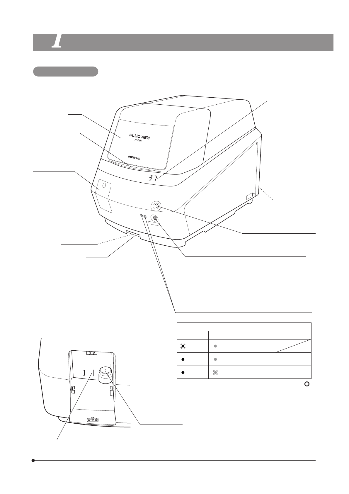
Main Unit: FV10C-W3
FLUOVIEW FV10i-LIV
Cover
Close lever
Water tank cover
Water tank for
immersed objective
(Approx. 200 ml) is
built in.
Water stop valve
Water tray
View when the water tank cover is
opened
Incubator temperature
· Blinks during warmup.
· “- -” is displayed when
the temperature setting is OFF.
CO2 inlet port
Cover lock buttons
Push the botton to open the cover.
When setting the sub-switch to ON
· Press it shortly to start up the main unit with the heater
ON.
· Press and hold it until a short beep is generated (about
3 seconds) to start up the main unit with the heater
OFF.
Sub-switch OFF
· Press and hold for 3 sec.
}Status LEDs when both the main and sub switches are ON.
LEDs
Left Right
Green
blinking
Green
lighting
Green
lighting
· The left LED lights in red when the main switch is set to “ ”
(ON).
· Both the left LED (green) and right LED (orange) blink when
the cover is open.
Orange
lighting
Orange
lighting
Orange
blinking
Laser Software
Initializing
Standby Not run
Standby Running
indicator
Sub-switch
Status LEDs
Water level
window
Water inlet
With a cap and filter.
2
Page 6
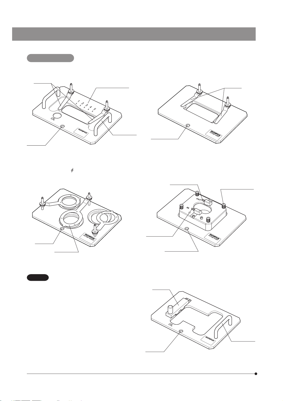
Specimen Holders
1. Specimen holder for slide glass: FV10C-HOS-2
Specimen
stoppers
Positioning
hole
Map area indicator
Holder handle
3. Specimen holder for 35 mm dish: FV10C-HOD3
2. Specimen holder for chamber: FV10C-HOC
Chamber
stopper
Positioning hole
4. Specimen holder for culture pod: FV10C-HOP
Culture solution
outlet
Top cover clamping
screws
x 4 pcs.
Positioning
hole
Dish stopper
CAUTION
To keep the internal temperature and humidity of
the incubator stable, be sure to place dummy
specimens in the unused specimen positions
when the number of specimens used is 1 or 2.
Culture solution
inlet
Positioning holes
5. Specimen holder for well slide: FV10C-HOW
Slide glass
stopper
Holder handle
Positioning
hole
3
Page 7

Power Supply Unit: FV10C-PSU
Main switch
Power cord
connector
FLUOVIEW FV10i-LIV
Output connector
Controller: FV10C-CU
}The software is pre-installed.
Software: FV10i-SW
}The display is not provided. Please prepare
a WUXGA (1920 x 1200 pixels) display.
Main switch
Dongle
4
Page 8

ASSEMBLY
Connecting the Cables
1
CAUTION
Be sure to set the main switches of the power supply unit and controller to “ ” (OFF) before connecting the
cables.
Attach the dongle
to the USB port.
Rear panel of the
FV10C-CU controller unit
Communication cable
Main switch
“ ” (OFF)
Rear panel of the
FV10C-W3
Power input cord
5
Power cord
}For the connection of the display, refer to the instruction manual for your display.
@²
Fig. 1
CAUTION
CAUTION
· Cables and cords are vulnerable to bend or twist. Do not apply
excessive force to them.
· Always use the power cord provided by Olympus. If no power
cord is provided, please select the power cord by referring to
the section “PROPER SELECTION OF THE POWER SUPPLY
CORD” at the end of this manual. If the proper power cord is
not used, Olympus can no longer warrant the electrical safety
performance of the equipment.
1. Insert the connector of the power cord to the connector on the power
supply unit.
Always ensure that the grounding terminal is safety grounded/
earthed. If the equipment is not grounded/earthed, Olympus
can no longer warrant the electrical safety performance of the
equipment.
2. Insert the power cord plug @ into the wall power outlet ².
Rear panel
of the FV10C-PSU
power supply unit
Page 9

Connecting the Tubes
2
FLUOVIEW FV10i-LIV
CAUTION
The tubes, CO2 gas cylinder and CO2 mixer are not included in the FV10i-LIV package. Please purchase
these accessories separately.
100% CO2 gas cylinder**
CO2 mixer*
Tube
Tube
Rear panel of
FV10C-W3
Diameter converter
Tube
Inner dia. 2 x Outer dia. 4 mm
Tube
Inner dia. 2 x Outer
dia. 4 mm
nipple
Ultrapure water
}As the CO2 concentration is reduced due to the incubator structure, please supply 6% CO2 gas. It will be turned into 5%
CO
2 gas inside the incubator.
* Recommended CO
**
When a 6% CO2 gas cylinder is used, connect a flow meter in place of the CO2 mixer.
2 mixer output flow: 150 ml/min. of 6% CO2 gas.
6
Page 10

Connecting the culture perfusion tubes to the culture pod
²
³
Peristaltic
pump
Tube
Inner dia. 2 x Outer
dia. 4 mm
Fig. 2
4
Cap @
1. Remove the cap @ provided on the left side of main body (Fig. 3).
Use the allen wrench included in the product. Loosen the stopper screw
from inside and remove the cap by bringing the stopper in horizontal
position.
2. Remove the cover ² of the incubator.
3. Remove the screw ³ by the allen wrench and remove the cap | provided
on the side of the cover (Fig. 2).
4. Connect the tubes to culture pod as illustrated in the Fig. 3.
}Connect the tube on the side of the peristaltic pump to OUT.
Connect the tube on the side of culture solution to IN.
5. Place the cover on the incubator. Use the space for the cap | to take out
the tubes.
Incubator
7
Culture solution
Fig. 3
Connecting the chemical stimulation tube to the culture pod
CAUTION
Be sure to connect to the OUT side make the amount of the culture solution 2 ml in order to prevent
bubble production in the culture solution.
Chemical syringe
Inner dia. 2 x Outer dia. 4 mm
Tube
FV10C-W3
OUT
IN
Culture pod
Culture pod
Page 11

Preparation Before Placing the Specimen
3
²
³
FLUOVIEW FV10i-LIV
Water Injection in the Incubator (Fig. 4)
}Water injection is not necessary when the internal temperature of the
incubator is not set (OFF).
1. Push and hold the cover button @, and lift the cover.
2. Remove the cover ² from the incubator.
3. Take out the rubber CO
pour ultrapure water until it fills about 70% of the water reservoir.
4. Re-place the rubber CO
tube is immersed underwater.
5. The cover of the incubator is to be placed after having placed the
specimen.
2 feed tube holder ³ from the water reservoir and
2 feed tube holder to that the extremity of the
@
Fig. 4
Fig. 5
²
@
Water Injection in the Objective Water Tank (Fig. 5)
}Confirm that the drain cock is closed before filling water. Please refer to
“Refilling Water in the Objective Water Tank” in P.11 for the detail information
of the drain cock.
1. Push the dented portion of the water tank cover to open it.
2. Remove the cap from the water inlet @ and pour ultrapure water gently
(so that the filter can pass the water).
3. Fill the water tank while observing the water level window ².
The water level is not visible until the water approaches the full capacity
of 200 ml.
}Be sure to fill the water tank completely when the time-lapse operation is
to be performed.
The amount of water injected into the objective tip is 0.1 ml per time.
When the tank is full, water injection is possible for about 2,000 times.
}The water inlet has a filter inserted in the way. If the water feed is extremely
slow, take out the filter and clean* or change it.
* Clean the filter frame with ultrapure water after taking it out and reversing
it.
8
Page 12

Draining of Water Pump (Fig. 6)
The water pump for the objective lens contains water to prevent dryness. At the first startup of FV10i-LIV, or after emptying
and refilling the objective water tank with water, drain water from the water pump according to the procedures below.
1. Open the body cover and remove the sample holder.
2. Start Software and Logon.
3. Click on the button. Water feeding starts and the color
of the button changes to red.
Fig. 6
4. Wait for the color of the
gray.
5 minutes later, water feeding stops and the color of the button returns
automatically to gray.
5. Return the sample holder and the body cover back to the original position.
button to return automatically to
Placing the Specimen
4
CAUTION
NOTE
· If you attempt to place the specimen directly on the specimen holder installed in the main unit, it may drop
inside the main unit.
Be sure to take out the specimen holder and place the specimen on it outside the main unit.
· If the sample falls within the device, pick up the sample with the tweezers made of bamboo or plastic, or the
stick wrapped by the adhesive tape.
If you open the cover, the temperature within the incubator drops. When you replace samples, etc., do so
quickly. After you open the cover, wait for a while to stabilize the temperature within the incubator.
(When the use environment temperature is 25°C and the cover open time is less than 3 minutes, wait for
approx.30 minutes.)
Place a dummy specimen until the internal temperature of the incubator rises to the optimum temperature (35 to
37°C).
When the specimen holder for
Without specimens placed, the internal temperature of the incubator may become unstable.
a
²
8
³
9
8
@
(Figs. 7 to 9)
35 mm dish is used, place dummy specimens in all of the three positions.
1. Push and hold the cover buttons @, and lift the cover.
2. Remove the cover of the incubator.
3. Place the specimen.
} When using a culture pod, it is necessary to remove its top cover, set the
35 mm dish and connect the tubes (see page 7).
Specimen other than well slide/culture pod specimen
· Place the specimen in the specified specimen holder ² and fix the
specimen with the specimen stopper ³ (Fig. 7).
A slide glass specimen should be placed with the cover glass facing
downward.
9
Fig. 7
Page 13

4
Fig. 8
5
7
FLUOVIEW FV10i-LIV
Well slide specimen (Fig. 8)
Remove media chamber from the slide and cover glass on top
surface. Shield it with proper method.
Place the slide with cover glass facing downward for imaging.
· Loosen the knob | of the slide glass stopper and lift it.
· Place the well slide 5 along the left edge, lower the slide glass stopper
and tighten the knob |.
}When using the specimen holder for slide glass, memorize the map area
indicator number 7 aligned with the position of the observation target 6
and use the same position in later observation/acquisition (Fig. 9).
6
Fig. 9
4. Hold the specimen holder ² horizontally by the holder handle 8 or
pillars of the specimen stoppers and place the specimen holder on the
specimen holder mount so that the positioning hole 9 of the specimen
holder comes on the front (Fig. 7).
5. Re-place the cover of the incubator.
6. Push down the close lever a and confirm that a click sound is generated
(Fig. 7).
}If the cover is not closed completely, the internal temperature of the
incubator may become unstable and the laser beam will not be output,
making observation impossible.
10
Page 14

ROUTINE MAINTENANCE
Cleaning the Objective
1
}Clean the object front after completing observation and acquisition.
1. Remove the specimen holder and wipe water attached to the object front using a piece of cleaning paper or clean cloth.
2. If the object front is stained, moisten the cleaning paper or cloth with commercially available absolute alcohol.
Refilling/Draining Water in the Incubator
2
· Check the amount of water in the incubator at proper timing, for example when replacing the specimen, and refill water
as required.
· After completing observation/acquisition, take out the rubber tube from the water reservoir of the incubator without
stopping the CO
After this, drain water from the water reservoir.
Refilling Water in the Objective Water Tank
3
2 feed (in order to drain water from inside the rubber tube).
· Check the water level of the water tank periodically through the water level window, and refill water as required.
· The display shows an alarm when the water amount gets insufficient.
Draining Water from the Water Tank (Figs. 10 & 11)
}When the system is not to be used for more than two weeks, drain the
water because the water quality would degrade.
}For safety in transportation, shut down the software and turn the sub-
switch of the main unit to OFF.
1. Slide out the water tray @.
2. Attach the drain tube ² at the drain outlet.
3. Prepare the relatively large bucket, and place it so that water from the
drain tube enters into the bucket.
4. Twist the drain cock ³ to start draining.
@
Fig. 10
²
5. When draining is finished, return the drain cock ³ to the original position.
6. Remove the drain tube ² and return the water tray @ to the original
position.
CAUTION
4
Be sure to use the drain tube provided by Olympus.
Draining Water from the Water Tray
· The water tray @ pools excess water in the main unit. Slide out the tray
periodically and drain water from it.
(Fig. 10)
11
3
Fig. 11
Page 15

FLUOVIEW FV10i-LIV
Disinfection and Sterilization
5
}If a hazardous specimen is attached to or splashed in the specimen holder or the incubator, immediately disinfect or
sterilize it.
Do not leave the attached substance, for it will harden and become hard to remove.
Disinfection
· Applicable position: Inside the incubatorand on various specimen holders. (excluding the rubber part @ of the
FV10C-HOW).
· Procedure: Moisten a clean cloth with disinfecting alcohol and wipe with it.
Do not rub the name plate with a strong force to prevent it from being peeled off.
Sterilization
@
· Applicable position: Cover on the culture pod.
· Procedure: Use autoclaving (high-pressure steam sterilization)
at 121°C for 20 minutes.
After sterilization, dry the specimen holder before reuse.
12
Page 16

PROPER SELECTION OF THE POWER SUPPLY CORD
If no power supply cord is provided, please select the proper power supply cord for the equipment by referring to “ Specifications ” and
“ Certified Cord ” below:
CAUTION:
In case you use a non-approved power supply cord for Olympus products, Olympus can no longer warrant the
electrical safety of the equipment.
Specifications
Voltage Rating
Current Rating
Temperature Rating
Length
Fittings Configuration
125V AC (for 100-120V AC area) or, 250V AC (for 220-240V AC area)
6A minimum
60°C minimum
3.05 m maximum
Grounding type attachment plug cap. Opposite terminates in molded-on IEC configuration appliance coupling.
Table 1 Certified Cord
A power supply cord should be certified by one of the agencies listed in Table 1 , or comprised of cordage marked with an
agency marking per Table 1 or marked per Table 2. The fittings are to be marked with at least one of agencies listed in
Table 1. In case you are unable to buy locally in your country the power supply cord which is approved by one of the
agencies mentioned in Table 1, please use replacements approved by any other equivalent and authorized agencies in
your country.
Country Agency
Argentina
Australia
IRAM
SAA
Certification
Mark
Country Agency
Italy
Japan
IMQ
JET, JQA, TÜV,
UL Japan / METI
Certification
Mark
13
Austria
Belgium
Canada
Denmark
Finland
France
Germany
Ireland
ÖVE
CEBEC
CSA
DEMKO
FEI
UTE
VDE
NSAI
Netherlands
Norway
Spain
Sweden
Switzerland
United
Kingdom
U.S.A.
KEMA
NEMKO
AEE
SEMKO
SEV
ASTA
BSI
UL
Page 17

FLUOVIEW FV10i-LIV
Table 2 HAR Flexible Cord
APPROVAL ORGANIZATIONS AND CORDAGE HARMONIZATION MARKING METHODS
Approval Organization
Comite Electrotechnique Belge
(CEBEC)
Verband Deutscher Elektrotechniker
(VDE) e.V. Prüfstelle
Union Technique de l´Electricite´
(UTE)
Instituto Italiano del Marchio di
Qualita´ (IMQ)
British Approvals Service for Electric
Cables (BASEC)
N.V. KEMA
SEMKO AB Svenska Elektriska
Materielkontrollanstalter
Österreichischer Verband für
Elektrotechnik (ÖVE)
Danmarks Elektriske Materialkontroll
(DEMKO)
Printed or Embossed Harmonization Marking (May be located on
jacket or insulation of internal wiring)
CEBEC <HAR>
<VDE> <HAR>
USE <HAR>
IEMMEQU <HAR>
BASEC <HAR>
KEMA-KEUR <HAR>
SEMKO <HAR>
<ÖVE> <HAR>
<DEMKO> <HAR>
Alternative Marking Utilizing
Black-Red-Yellow Thread (Length
of color section in mm)
Black Red Yellow
10 30 10
30 10 10
30 10 30
10 30 50
10 10 30
10 30 30
10 10 50
30 10 50
30 10 30
National Standards Authority of Ireland
(NSAI)
Norges Elektriske Materiellkontroll
(NEMKO)
Asociacion Electrotecnica Y
Electronica Espanola (AEE)
Hellenic Organization for
Standardization (ELOT)
Instituto Portages da Qualidade
(IPQ)
Schweizerischer Elektro
Technischer Verein (SEV)
Elektriska Inspektoratet
Underwriters Laboratories Inc. (UL) SV, SVT, SJ or SJT, 3 X 18AWG
Canadian Standards Association (CSA) SV, SVT, SJ or SJT, 3 X 18AWG
<NSAI> <HAR>
NEMKO <HAR>
<UNED> <HAR>
ELOT <HAR>
np <HAR>
SEV <HAR>
SETI <HAR>
30 30 50
10 10 70
30 10 70
30 30 70
10 10 90
10 30 90
10 30 90
14
Page 18

MEMO
Page 19

Page 20

Shinjuku Monolith, 3-1, Nishi Shinjuku 2-chome, Shinjuku-ku, Tokyo, Japan
Wendenstrasse 14-18, 20097 Hamburg, Germany
3500 Corporate Parkway, Center Valley, Pennsylvania 18034-0610, U.S.A.
491B River Valley Road, #12-01/04 Valley Point Office Tower, Singapore 248373
31 Gilby Road, Mount Waverley, VIC., 3149, Melbourne, Australia
Blue Lagoon Drive, Suite 290 Miami, FL 33126, U.S.A.
5301
Printed in Japan on June 01, 2011 M 002–04
 Loading...