

Page 1

User’s Manual
A
FLUOVIEW
FV1000
CONFOCAL LASER SCANNING
BIOLOGICAL MICROSCOPE
[OPERATION] FV10-SW Ver 5.0c
Petition
This user’s manual is for the software to be run on Olympus FLUOVIEW FV1000 Confocal Laser
Scanning Biological Microscope. To ensure safety, obtain optimum performance and familiarize
yourself fully with this product, we recommend that you study this manual thoroughly before operation.
This user’s manual is composed of two volumes including “OPERATION INSTRUCTIONS” and
“MAINTENANCE”. Together with this manual, please also read the “SAFETY GUIDE”, “HARDWARE
GUIDE” of User’s manual FLUOVIEW FV1000 and the instruction manual of the microscope in order to
understand overall operation methods. To ensure the safety operation of laser system, we recommend
you to study the manual of each laser and the light source equipment besides this manual.
Retain this manual in an easily accessible place near a system for future reference.
X7274
Page 2

Page 3

CAUTION
CAUTION
1. Reproduction, copying or duplication of a part or all of this software and manual is prohibited.
2. The information described in this manual may be subject to change without notice.
Registered Trademarks
Microsoft, Microsoft Windows, Excel for Windows are registered trademarks of Microsoft Corporation.
Other brand names and product names are trademarks or registered trademarks of their respective owners.
Page
1
Page 4

FLUOVIEW MANUAL CONFIGURATION
FLUOVIEW MANUAL CONFIGURATION
The FLUOVIEW system uses two manuals including this “User’s Manual” and the on-screen
manual built into the software (“Online Help”).
The User’s Manual is composed of the five following volumes and subject matter:
OPERATION INSTRUCTIONS
Describes the operation procedures of the FLUOVIEW system, for example, methods
for image acquisition and various image processing.
1 Getting Started FLUOVIEW................................................................................ 1-1
2 APPLIED OPERATIONS.................................................................................... 2-1
Appendix A List of Hot Keys.................................................................................. A-1
Appendix B Glossary............................................................................................. B-1
Appendix C USER REGISTRATION OF FV1000 ................................................. C-1
Appendix D Change of Default Folder for [File I/O] Panel..................................... D-1
Appendix E List of Functions in the [Active Overlays] Dialog Box......................... E-1
Appendix F Hand Switch and Microscope Frame Function Allocation .................. F-1
MAINTENANCE
Describes maintenance of the FLUOVIEW system.
1 Software Setup................................................................................................... 1-1
2 Maintenance of Major System Units................................................................... 2-1
3 Setting the Confocal Aperture ............................................................................3-1
TROUBLESHOOTING
Describes countermeasures in case trouble occurs.
1 TROUBLESHOOTING GUIDE ........................................................................... 1-1
For Online Help, please see “1-3 Online Help” in “OPERATION INSTRUCTIONS” of this
manual.
2
Page
Page 5

NOTATIONS IN THIS MANUAL
This manual complies with the following notations.
Notation of Caution, Notes and Tips
Notation Description
NOTATIONS IN THIS MANUAL
Caution to prevent injuries to the user or damage to the
product (including surrounding objects).
NOTE
TIP
Note for the user.
Hint or one-point advice for user reference.
Notation of panel, Command Buttons and Dialog Boxes
Notation Description
[Acquire] panel The name of a panel, dialog box, list box or check box is
enclosed inside square brackets ([ ]).
<OK> button
<Open File> button
The name of a button in a panel or dialog box is enclosed
inside angled brackets (< >).
Notation of Mouse Operations
Notation Description
clicking Action of pressing, then immediately releasing the mouse
button.
double-clicking Action of clicking the mouse button twice in quick succession.
dragging Action of moving the mouse while holding down the mouse
button, then releasing the mouse button at the desired
destination.
(Note) In this manual, clicking, double-clicking and dragging involves pressing the left button
of the mouse, unless otherwise specified.
Page
3
Page 6
NOTATIONS IN THIS MANUAL
Notation of key operations
Notation Description
Enter
The name of a key is enclosed inside .
Alt
+
Direction keys
F1
The positive sign (+) expresses the combination of more than
one key operation.
For example,
key while holding the
F1
Generic names given to the
keys.
↓
Alt
+
refers to pressing the
F1
key down.
Alt
→
,
←
,
and
↑
Notation of system-specific terms
Notation Description
XY observation
(Other observations)
Note that some of the panels and dialog boxes shown in this manual are not the precise
reproductions of the originals. Some windows are resized to facilitate the reading and some
grayed-out characters are printed in readable characters.
Refers to observation with XY scanning.
(The same principle also applies to other observations such
as XZ, Xt, XYZ, XYt and XYZt.)
4
Page
Page 7
Software Functional Configuration
This software uses panel-type windows.
Usually, it is required to “select a menu then select the command to be executed” in order to
execute a function provided by software. With the panel system, a software function can be
executed easily by “selecting the panel page tab of the function to be executed”, just like
when using a system notebook or file folder.
Function Window and Image Window
The FLUOVIEW software is organized by two kinds of windows, the function windows and
the image .window.
The function windows include the [Acquire], [File I/O], [Tile], [Process], [Analyze] and
[Visualize] panels.
The image .window shows either the [Live] panel or the panel image loaded from a file
([(filename)] window).
The function window
Software Functional Configuration
NOTE
The image window
In this manual, the function windows are referred to simply using their
page tabs.
Namely, the [File I/O] panel of function windows is referred to simply as the
[File I/O] panel.
Page
5
Page 8

Software Functional Configuration
A
A
Panel Structure of the Software
This software cannot show the all function panels at a glance.Please use the following list of
the panels for reference in scrolling.
Acquire
Settings
Z Stage
Time Series
Dyes
Lasers Sets the intensity of laser and other option for image acquisition.
File I/O
Tile
Process
Math
Filters
Histogram
Experiment Editor
Analyze
Single
Sets up the image acquisition and executes actual acquisition.
Sets the zooming ratio and observation mode for image acquisition.
Sets the microscope light path for image acquisition.
Sets the Z-direction scanning range for image acquisition.
Sets the interval period for image acquisition.
Sets the fluorescence dye method for image acquisition and reagent for
each channel.
Saves, loads and deletes images.
Changes the image display method.
Processes the acquired images.
Performs mathematical and logical operations between images.
Filters images.
Changes the image contrast.
ppends two images, adds and extracts the channel.
nalyzes image data.
Obtains the intensity values, intensity distribution, length, area and
average intensity in images.
Series
Visualize
Orientation
Other Options
6
Page
Obtains the change in the sum of intensity values in images.
Constructs an image from a different viewpoint or displays a 3D image.
Sets the image rotation angle, direction and number.
Sets the various 3D Rendering.
Page 9
Icons Executed by Dragging & Dropping
This software selects image files and observation methods (dye name) by means of
dragging & dropping. This allows simple selection based on an intuitive operation of
“selecting an icon (image file or observation method), dragging it to the desired position and
dropping it there”.
Software Functional Configuration
Page
7
Page 10
Software Functional Configuration
Identification of Images Depending on the Observation Methods
Image Icon Significance
XZ observation
XZ observation, 2-channel mode
Xt observation
Xt observation, 2-channel mode
XZT observation
XZT observation, 2-channel
mode
XY observation
XY observation, 2-channel mode
XYt observation
XYt observation, 2-channel
mode
On many occasions, FLUOVIEW displays image
icons to allow identification of the observation
method used when each image is acquired. (See
table on the left.)
When the [File I/O], [Tile], [Process], [Analyze] or
[Visualize] panel is selected, the icon of the image
selected in the image window is displayed in a
frame at the top of the function panel. The image
icons are also displayed in the [Icon] field in the
[Files] list box in the [File I/O] panel or during
dragging of an image file.
Use these icons to identify the observation methods
used in image acquisition.
TIP
In all observation modes, the icons for 3
XYZ observation
XYZ observation, 2-channel
mode
XYZt observation
XYZt observation, 2-channel
mode
Point Scan
Animation image
Stereo 3D image: Image to be
viewed with color eyeglasses.
3 or more channels
or more channels are identical.
8
Page
Page 11

O
O
P
P
E
E
N
IIN
R
R
S
A
A
S
TII
T
T
T
R
R
O
O
U
U
N
N
C
C
TII
T
O
O
N
N
S
S
On This Volume
This volume describes the operating procedures of the
FLUOVIEW FV1000 system.
“Getting Started FLUOVIEW” contains information on the basic
operation flow until acquisition of XY images.
“APPLIED OPERATIONS” provides detailed operating
procedures of the system.
Please read this volume so that you can understand the system
before use.
Page 12

Page 13

CONTENTS
1 Getting Started FLUOVIEW 1-1
1-1 Basic Operations .............................................................................1-1
1-1-1 Microscope .................................................................................................... 1-1
1-1-2 General Mouse Operation Procedures.......................................................... 1-7
1-1-3 Names of Major Panel and Window Controls and Their Functions............... 1-8
1-2 Outline of LSM Observation Procedures ......................................1-9
1-2-1 Turning Power On ....................................................................................... 1-11
1-2-2 Focusing on the Specimen.......................................................................... 1-12
1-2-2-1 Combination with BX .......................................................................................1-12
1-2-2-2 Combination with IX81 FVF .............................................................................1-14
1-2-3 Setting the LSM Light Path.......................................................................... 1-16
1-2-3-1 Combination with Upright Microscope (BX).....................................................1-16
1-2-3-2 Combination with Inverted Microscope (IX81 FVF) .........................................1-18
1-2-4 Selecting the Dyeing Method ...................................................................... 1-20
1-2-5 Selecting the Filters..................................................................................... 1-23
1-2-6 Setting the ND Filters ..................................................................................1-26
1-2-7 Setting the Observation Condition............................................................... 1-27
1-2-7-1 Setting the Objective Magnification .................................................................1-27
1-2-7-2 Setting the Zoom Ratio to 1X...........................................................................1-28
1-2-7-3 Setting the Channels .......................................................................................1-28
1-2-7-4 Setting the Highest Scan Speed......................................................................1-29
1-2-7-5 Setting the XY Observation Mode ...................................................................1-30
1-2-7-6 Repeated Scanning Operation ........................................................................1-30
1-2-7-7 Setting the Cross-section to be Observed.......................................................1-31
1-2-7-8 Setting the Area to be Observed .....................................................................1-32
1-2-7-9 Setting a Lower Scan Speed ...........................................................................1-32
1-2-7-10 Stopping Repeated Scanning........................................................................1-33
1-2-8 Acquiring Image ..........................................................................................1-33
1-2-9 Saving Image .............................................................................................. 1-34
1-2-10 Exiting from the Software, Turning Power Off ........................................... 1-35
Page 14

CONTENTS
1-3 Online Help..................................................................................... 1-36
2 APPLIED OPERATIONS 2-1
2-1 General Operation Procedure ........................................................2-1
1-3-1 Function Help ..............................................................................................1-36
1-3-2 Microscope Help..........................................................................................1-37
1-3-2-1 Configuring the Microscope ............................................................................ 1-40
1-3-2-2 Parfocality Correction and Jog Sensitivity Adjustment ................................... 1-46
1-3-2-3 Configuring the Filters (When using a filter system) ....................................... 1-52
1-3-2-4 Configuring the filters (When using a spectral detecting system)................... 1-56
1-3-2-5 Setting the C.A. Diameters ............................................................................. 1-59
2-1-1 Image Acquisition Procedure (Section (A))....................................................2-3
2-1-2 Image Acquisition Procedure in an Observation Mode (Section (B)) ............2-4
2-1-3 Examples of Operation Procedures...............................................................2-5
2-2 Image Acquisition............................................................................ 2-7
2-2-1 Image Acquisition in XY Observation Mode ..................................................2-8
2-2-1-1 Configuring the Microscope .............................................................................. 2-9
2-2-1-2 Setting the Filters ............................................................................................ 2-15
2-2-1-3 Setting the ND Filters...................................................................................... 2-17
2-2-1-4 Setting the Observation Condition .................................................................. 2-19
2-2-1-5 Acquiring Image .............................................................................................. 2-28
2-2-1-6 Acquiring Image in Accumulation Mode.......................................................... 2-29
2-2-1-7 Saving the Acquired Image in File .................................................................. 2-33
2-2-2 Image Acquisition in Other Observation Modes ..........................................2-34
2-2-2-1 XZ Observation Mode ..................................................................................... 2-34
2-2-2-2 XT Observation Mode ..................................................................................... 2-38
2-2-2-3 XZT Observation Mode................................................................................... 2-40
2-2-2-4 XYZ Observation Mode................................................................................... 2-46
2-2-2-5 XYT Observation Mode................................................................................... 2-51
2-2-2-6 XYZT Observation Mode ................................................................................ 2-55
2-2-3 Differences in Image Acquisition Method Between Fluorescent and Transmitted
Page 15

CONTENTS
Images......................................................................................................... 2-61
2-2-3-1 Monochrome Image.........................................................................................2-61
2-2-3-2 Dual-Fluorochrome Image ...............................................................................2-64
2-2-3-3 Transmitted Image...........................................................................................2-67
2-2-4 Image Acquisition by Rotating It (Rotation Scan)........................................ 2-71
2-2-5 Image Acquisition of Only the Rectangular Position (Clip Scan)................. 2-72
2-2-6 Image Acquisition by Magnifying the Rectangular Position (Zoom-In Scan)2-75
2-2-7 High-Speed Image Acquisition .................................................................... 2-78
2-2-8 Image acquisition to prevent crosstalk between fluorescence (Sequential Scan)
.................................................................................................................... 2-79
2-2-8-1 Virtual Channel Function .................................................................................2-82
2-2-9 Image Acquisition of a Line at Desired Angle.............................................. 2-88
2-2-10 Display the change of image intensity (Point Scan) .................................. 2-89
2-2-11 Image Acquisition on Desired Line (XZ, XT or XZT Observation)............. 2-94
2-2-12 Image Acquisition in the Laser Excitation Mode........................................ 2-97
2-2-12-1 Making REX Mask File ..................................................................................2-98
2-2-12-2 Example of FRAP experiment .....................................................................2-103
2-2-13 Notes for image acquisition ..................................................................... 2-112
2-2-13-1 Memory of setting information for scanning region......................................2-112
2-3 Saving, Opening and Shredding Images................................... 2-113
2-3-1 Saving Images........................................................................................... 2-116
2-3-1-1 Saving Images As a Series............................................................................2-116
2-3-1-2 Saving a Display ............................................................................................2-118
2-3-1-3 Saving Specified Area of Image ....................................................................2-120
2-3-1-4 Saving Animation Images ..............................................................................2-123
2-3-1-5 File Types Available for Save ........................................................................2-125
2-3-2 Opening Previously Saved Images ........................................................... 2-132
2-3-3 Shredding Images .....................................................................................2-133
2-3-4 Saving Comment Together with Image ..................................................... 2-135
2-3-5 Checking the Image Information/Acquisition Parameters.......................... 2-138
2-3-6 Saving the Image Information/Observation Condition............................... 2-142
2-3-7 Saving/Reading the Region File................................................................ 2-145
Page 16

CONTENTS
2-4 Protocol processor...................................................................... 2-150
2-3-7-1 Saving the Region File.................................................................................. 2-145
2-3-7-2 Reading the Region File ............................................................................... 2-147
2-4-1 Starting the Protocol Processor.................................................................2-151
2-4-2 Editing the Protocol ...................................................................................2-152
2-4-2-1 Description of Setting Items .......................................................................... 2-153
2-4-2-2 Command List ............................................................................................... 2-160
2-4-2-3 Protocol Repetition Processing..................................................................... 2-165
2-4-2-4 Input supporting function............................................................................... 2-167
2-4-2-5 Protocol procedure supporting function ........................................................ 2-169
2-4-3 Saving the Protocol....................................................................................2-170
2-4-4 Executing the Protocol...............................................................................2-172
2-4-5 Loading a Protocol.....................................................................................2-174
2-4-6 Loading a protocol of previous format .......................................................2-175
2-4-7 COM Communication function................................................................... 2-177
2-4-8 Example of assembling a protocol.............................................................2-178
2-4-8-1 Example of Setting Procedure of FRAP Observation ................................... 2-178
2-4-8-2 Example of Setting Procedure of XYT Observation for hours (Protocol using
repetition processing) ........................................................................................... 2-187
2-4-9 Pop-up Menu .............................................................................................2-195
2-4-10 Restrictions of [PAPP] setting.................................................................. 2-196
2-4-10-1 Restrictions with [Mode] and [Sub Mode] ................................................... 2-196
2-5 Changing the Image Display Method......................................... 2-198
2-5-1 Displaying an Image in Simulated Colors .................................................. 2-198
2-5-2 Editing the LUT (Look Up Table) ...............................................................2-200
2-5-2-1 LUT Graph Editing According to Colors........................................................ 2-200
2-5-2-2 LUT Graph Editing by Gamma Correction.................................................... 2-202
2-5-3 Switching the Displayed Channels (Ch1 – Ch5)........................................2-203
2-5-4 Displaying Images of Multiple Channels Simultaneously (Side By Side Views,
Over And Under Views, Single View) ........................................................2-204
2-5-4-1 Displaying Images Separately Per Channel (Side By Side Views, Over And Under
Views) ................................................................................................................... 2-205
Page 17

CONTENTS
2-5-4-2 Displaying Merged Image of Multiple Channels (Single View)......................2-206
2-5-5 Changing the Number of Divided Images ................................................. 2-208
2-5-5-1 Increasing the Number of Divided Images ....................................................2-208
2-5-5-2 Decreasing the Number of Divided Images...................................................2-210
2-5-6 Switching the Display Method of Multiple Images ..................................... 2-211
2-5-7 Displaying Multiple Image Slices Together ............................................... 2-213
2-5-7-1 Displaying Multiple Images Per Channel.......................................................2-214
2-5-7-2 Displaying Images of Two Channels Together..............................................2-216
2-5-7-3 Displaying Time-Lapse Images .....................................................................2-217
2-5-7-4 Displaying Multiple Multiple sections Images ................................................2-218
2-5-7-5 Displaying Same Images in Different Display Methods.................................2-218
2-5-7-6 Re-arranging Images Using the Same Display Method ................................2-221
2-5-7-7 Displaying Different Images Together ...........................................................2-221
2-5-8 Magnifying/Reducing an Image................................................................. 2-224
2-6 Image Processing ........................................................................ 2-225
2-6-1 Filtering...................................................................................................... 2-225
2-6-1-1 Contour Enhancement...................................................................................2-226
2-6-1-2 Noise Reduction ............................................................................................2-229
2-6-1-3 Image Sharpening .........................................................................................2-230
2-6-1-4 DIC Correcting DIC Level Irregularities .........................................................2-231
2-6-2 Contrast Conversion.................................................................................. 2-233
2-6-3 Mathematical Operations Between Images............................................... 2-236
2-6-3-1 Image Addition...............................................................................................2-236
2-6-3-2 Image Subtraction..........................................................................................2-239
2-6-3-3 Image Multiplication .......................................................................................2-239
2-6-3-4 Image Division ...............................................................................................2-240
2-6-3-5 NOT Image ....................................................................................................2-241
2-6-3-6 Image AND Image .........................................................................................2-243
2-6-3-7 Image OR Image ...........................................................................................2-244
2-6-3-8 Image XOR Image .........................................................................................2-244
2-6-4 Brightness overlap level between 2 channels (Colocalization).................. 2-246
2-6-4-1 Annotation Mode............................................................................................2-247
Page 18

CONTENTS
2-7 Image Analysis............................................................................. 2-274
2-6-4-2 Colocalization for series image data set ....................................................... 2-254
2-6-4-3 Image measurement ..................................................................................... 2-255
2-6-5 Appending image (Append).......................................................................2-258
2-6-5-1 Appending two images.................................................................................. 2-258
2-6-5-2 Appending image from several image data set ............................................ 2-262
2-6-6 Extract image (Crop)..................................................................................2-267
2-7-1 Checking the Intensity of a Specific Part ...................................................2-275
2-7-1-1 Intensity Values on a Line (Line Profile) ....................................................... 2-275
2-7-1-2 Intensity Values on a Planar Region (Bird’s Eye View) ................................ 2-278
2-7-2 Checking the Intensity Distribution of a Specific Part ................................2-283
2-7-2-1 Intensity Distribution on a Line (Histogram) .................................................. 2-283
2-7-2-2 Intensity Distribution on a Planar Region (Histogram).................................. 2-284
2-7-3 Image Measurement..................................................................................2-286
2-7-3-1 Length Measurement .................................................................................... 2-286
2-7-3-2 Area Measurement........................................................................................ 2-286
2-7-3-3 Measuring the Change in Mean Value of Intensity ....................................... 2-287
2-7-3-4 Measuring the Change in Integrated Intensity .............................................. 2-293
2-8 Building an Image from a Different Viewpoint.......................... 2-295
2-8-1 Building Extended Focus Image from XYZ Image.....................................2-295
2-8-1-1 Display Switching to Built Image................................................................... 2-295
2-8-1-2 Turning Built Image into Single Image .......................................................... 2-298
2-8-1-3 Turning Built Image into time series image................................................... 2-300
2-8-2 Building line images to be viewed in Z direction........................................2-301
2-9 Viewing 3D Image ........................................................................2-305
2-9-1 Successive Display of Images...................................................................2-307
2-9-1-1 Changing the Successive Display Speed ..................................................... 2-308
2-9-1-2 Changing the successive image display position ......................................... 2-309
2-9-2 Animation...................................................................................................2-310
2-9-3 Building Stereo 3D Images........................................................................2-312
2-9-4 Building a 3D Image to be Viewed Through Color (Red/Green) Eyeglasses2-314
2-10 Viewing Images Following the Progress of Time................... 2-316
Page 19

CONTENTS
2-10-1 Displaying Images Together.................................................................... 2-316
2-10-2 Displaying Images Successively .............................................................2-316
2-11 Transferring Data to Another Application...............................2-319
2-11-1 Transferring Analysis Data to Another Application.................................. 2-319
2-11-2 Transferring the Plot Image of Analysis Data to Another Application...... 2-322
2-11-3 Transferring Image Data to Another Application (Paint, etc.).................. 2-323
2-12 Entering Comment in Image .....................................................2-324
2-12-1 Writing Characters in Image.................................................................... 2-324
2-12-2 Displaying the Image Intensity ................................................................ 2-326
2-12-3 Displaying the X-coordinate/Y-coordinate of the Image .......................... 2-327
2-12-4 Drawing a Figure in Image ...................................................................... 2-328
2-12-5 Drawing a Scale in Image ....................................................................... 2-329
2-12-6 Drawing an Arrow in Image ..................................................................... 2-330
2-12-7 Drawing Color Bars in Image .................................................................. 2-331
2-12-8 Deleting Comment................................................................................... 2-332
2-12-9 Moving Comment ....................................................................................2-333
2-12-10 Changing the Comment Size ................................................................ 2-334
2-12-11 Changing the Comment Color............................................................... 2-335
2-12-12 Changing the Comment Font ................................................................ 2-336
2-13 Image Output at Printer.............................................................2-337
2-14 Merger/Extraction of Image Channels ..................................... 2-338
2-14-1 Setting the Range of Multiple Image Slices............................................. 2-338
2-14-2 Merging Image Channels ........................................................................ 2-339
2-14-3 Extracting Channels from Image ............................................................. 2-344
2-15 Changing the Chart Display Method........................................ 2-348
2-15-1 [Chart] Panel ...........................................................................................2-348
2-15-2 [Series] Panel .......................................................................................... 2-356
2-16 Pop-up Menus ............................................................................ 2-359
Appendix A List of Hot Keys A-1
Page 20

CONTENTS
Appendix B Glossary B-1
Appendix C USER REGISTRATION OF FV1000 C-1
Appendix C-1 User Registration.......................................................... C-1
Appendix C-2 Logging into the FV1000.............................................. C-4
Appendix C-3 Deleting a User ............................................................. C-5
Appendix D Change of Default Folder for [File I/O] Panel
D-1
Appendix E List of Functions in the [Active Overlays]
Dialog Box E-1
Appendix E-1 Coordinate Position Data..............................................E-1
Appendix E-1-1 X-Coordinate ................................................................................ E-1
Appendix E-1-2 Y-Coordinate ................................................................................ E-2
Appendix E-1-3 Other ............................................................................................ E-3
1 Z Position....................................................................................................................E-3
2 T Position....................................................................................................................E-3
3 Animation.................................................................................................................... E-3
Appendix E-2 Intensity Data .................................................................E-4
Appendix E-3 Other ...............................................................................E-5
Appendix E-3-1 Channel Number .......................................................................... E-5
Appendix E-3-2 Objective Power ........................................................................... E-5
Appendix E-3-3 Date of Image Capturing .............................................................. E-5
Appendix E-3-4 Time of Image Capturing.............................................................. E-5
Appendix E-3-5 Image File Name .......................................................................... E-5
Appendix F Hand Switch and Microscope Frame Function
Page 21

CONTENTS
Allocation F-1
Appendix F-1 Hand Switch Functions .................................................F-1
Appendix F-1-1 BX/BXWI .......................................................................................F-1
Appendix F-1-2 IX...................................................................................................F-2
Appendix F-2 Microscope Frame Functions .......................................F-3
Appendix F-2-1 BX .................................................................................................F-3
Appendix F-2-2 IX...................................................................................................F-4
Appendix F-2-3 Focus Adjustment Knob ................................................................F-5
1 BX............................................................................................................................... F-5
2 IX ................................................................................................................................ F-5
Page 22

Page 23
Getting Started FLUOVIEW/ Basic Operations
r
r
)
1 Getting Started FLUOVIEW
1-1 Basic Operations
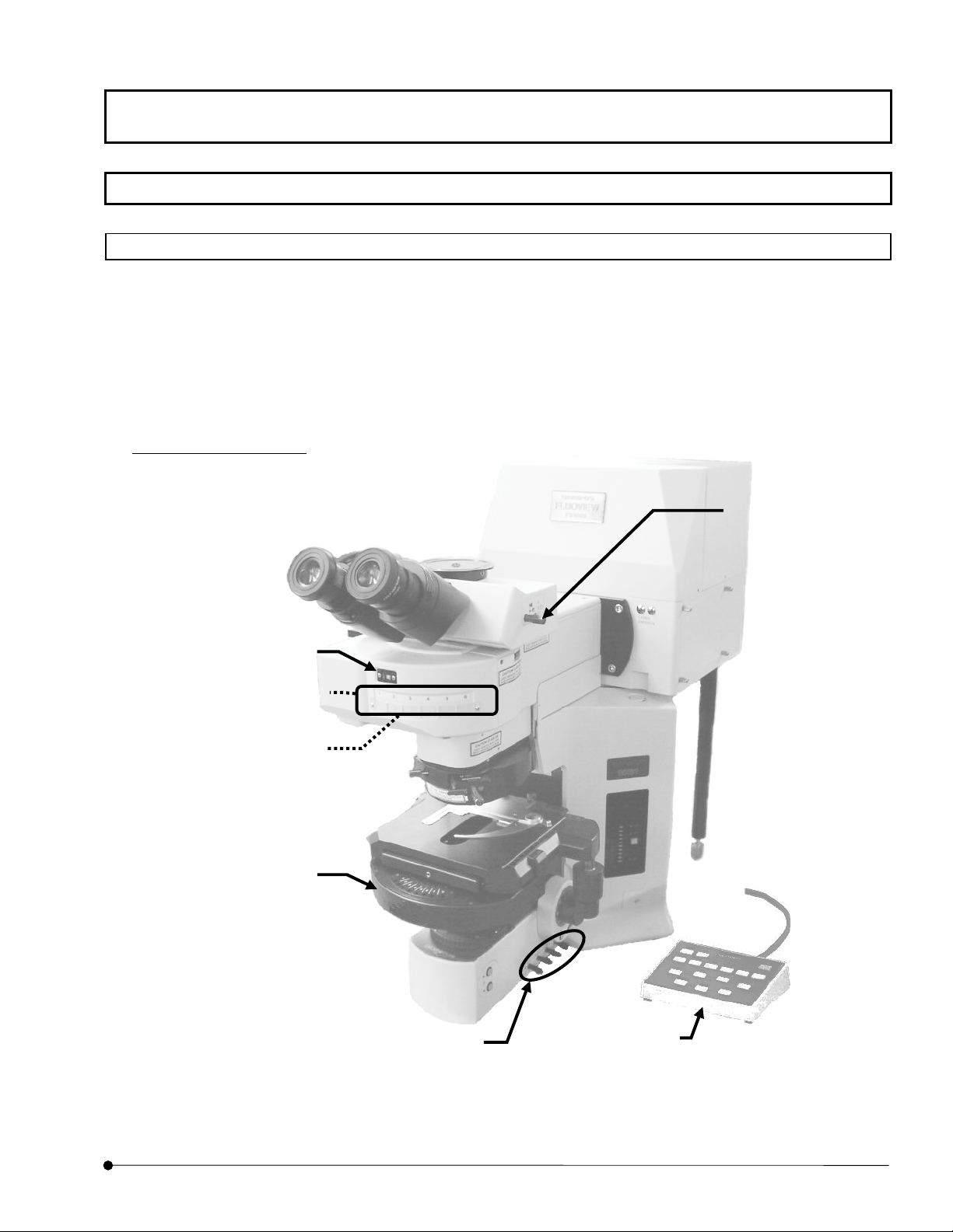
1-1-1 Microscope
The following figure shows the major controls of a microscope. The actual configuration of
the modules including the specimen stage, revolving nosepiece and lighting equipment may
differ from those shown below.
For detailed microscope operation procedures, refer to the instruction manuals of your
microscope.
Combination with BX61
(1) Light path
selector knob
(2) Cube turret /Cube display window
(This figure shows Cube display
window)
(4) Transmitted light DIC
FV5-DICTS/ WI-DICTH (with
BX61WI) (optional)
(3) Analyze
IX2-MDICT
(6) Universal
condense
(This figure shows the case of BX)
(5) Filters
LBD
ND6
ND25
When using BX61WI,
LBD
FFR
(7)Hand switch
U-HSTR2
(U-FH is optionally
available with BX61
OPERATION INSTRUCTIONS
Page
1-1
Page 24

Getting Started FLUOVIEW/Basic Operations
2
(1) Light path selector knob
Select the light path between the visual observation and photography observation.
• See the following table and set the knob to the position corresponding to the
required light path.
Light path selector knob Symbol Intensity Ratio
Pushed in 100% for the visual observation
Middle position
Pulled out 100% for photography observation
(2) Cube turret
Select the fluorescence observation tube by rotating the turret.
20% for the visual observation, 80%
for photography observation
• Engage the desired cube in the light path for visual fluorescence observation or
visual transmitted light observation.
• For laser microscopy, rotate the turret to page tab
state that mirror cube is entered.)
(3) Analyzer IX2-MDICT
Polarizing plate for use in differential interference observation and polarized light
observation.
• Rotate the turret to engage the IX2-MDICT in the light path for visual transmitted
light differential interference observation or transmitted polarized light observation.
(4) Transmitted light DIC slider U-DICTS/WI-DICTHRA (built-in FV10-SRE or FV10-
SNPXLU of BX61WI)
This is the prism for use in differential interference observation.
• Engage the transmitted light DIC in the light path for laser differential interference
observation or visual transmitted light differential interference observation.
Leaving the transmitted light DIC engaged during laser fluorescence observation will
1
. (Set cube turret in the
degrade the resolution somewhat. We recommend disengaging the transmitted light
DIC from the light path when simple laser fluorescence observation is required.
OPERATION INSTRUCTIONS
1-
Page
Page 25

Getting Started FLUOVIEW/Basic Operations
NOTE
(5) Filters
These filters are used to adjust the transmitted light.
• Be sure to disengage any filter from the light path for transmitted observation using
lasers. Leaving a filter engaged in the light path will degrade the image quality.
When you perform transmitted observation using laser with BX61WI, use the filter
knob to disengage the LBD from the light path and engage the FR (Frost) into the
light path. Disengaging the FR (Frost) from the light path may generate interference
fringes on an image.
(6) Universal condenser
With transmitted light differential interference observation using an
immersion objective, set the microscope’s field diaphragm so that
it circumscribes the field of view. Otherwise the contrast may
degrade. (This applies to both visual observation and laser
differential interference observation.)
Condenser for transmitted lighting. In addition, the rotary turret for the transmitted light
DIC prism and the polarizing plate for differential interference observation (polarizer)
are also provided.
• To perform differential interference observation, engage the transmitted light DIC
prism matching the objective in use in the light path (For both visual observation and
laser differential interference observation).
• To perform visual differential interference observation or laser differential
interference observation, engage the polarizing plate in the light path.
(7) Hand switch U-HSTR2 (U-FH is optionally available with BX61/BX61WI)
This is the hand switch to operate the BX motorized system.
NOTE
Connect the filter wheel of BX to connector of the following in the
back of UCB.
FW0: FW1
•
FWR: FW2
•
FWT: FW3
•
OPERATION INSTRUCTIONS
Page
1-3
Page 26
Getting Started FLUOVIEW/Basic Operations
y
)
r
Combination with IX81 FVF
(4) Condense
(5) Filters
(6) Light path selector button
(1)Fluorescence mirror
unit
((2) Analyzer IX-MDICT
Optionall
installed
(4) Transmitted light
DIC slider
U-DICTS (optional)
(6)Hand switch
U-HSTR2
(U-FH is optionally
available.)
OPERATION INSTRUCTIONS
1-4
Page
Page 27

Getting Started FLUOVIEW/Basic Operations
5
(1) Fluorescence mirror unit
Select the fluorescence observation tube by rotating the turret.
• Engage the desired cube in the light path for visual fluorescence observation.
• For laser microscopy, rotate the turret to page tab
mirror cube is entered.)
(2) Analyzer IX2-MDICT
Polarizing plate for use in differential interference observation and polarized light
observation.
• Rotate the cube turret to engage the IX2-MDICT analyzer into the light path for visual
transmitted light differential interference observation or transmitted polarized light
1
. (Set turret in the state that
observation.
(3) Transmitted light DIC slider U-DICTS
This is a prism for use in differential interference observation.
• Engage U-DICTS in the light path for laser differential interference observation or
visual transmitted light differential interference observation.
Leaving U-DICTS engaged during laser fluorescence observation will degrade image
quality somewhat. We recommend disengaging the U-DICTS from the light path
when simple laser fluorescence observation is required.
NOTE
With transmitted light differential interference observation using an
immersion objective, set the microscope’s field diaphragm so that it
inscribes the field of view. Otherwise the contrast may degrade.
(This applies to both visual observation and laser differential
interference observation.)
OPERATION INSTRUCTIONS
Page
1-
Page 28

Getting Started FLUOVIEW/Basic Operations
6
(4) Condenser, polarizing plate
Condenser for transmitted lighting.
In addition, the rotary turret for the transmitted light DIC and the polarizing plate for
differential interference observation (analyzer) are also provided.
• To perform differential interference observation, engage the transmitted light DIC
(optional) matching the objective in use in the light path (For both visual observation
and laser differential interference observation).
• To perform visual differential interference observation or laser differential
interference observation, engage the polarizing plate in the light path.
(5) Filters
These filters are used to adjust transmitted light.
• For transmitted observation using laser, disengage the LBD filter from the light path
and engage the FR (frost) filter in the light path by operating the filter levers. If the FR
filter is disengaged from the light path, the image may suffer from stripe interference.
(6) Light path selector button
Select the light path between the visual observation and photography observation.
• When <
• When <
(7) Hand switch (U-FH is optionally available.)
This is the hand switch to operate the IX motorized system.
> LED is lighted, visual observation can be done.
> LED is lighted, TV or photography observation can be done.
OPERATION INSTRUCTIONS
1-
Page
Page 29

7
1-1-2 General Mouse Operation Procedures
Use the mouse to select a command, character string or button. Use the left
button of the mouse unless otherwise specified.
To select or execute something: Clicking
To click the mouse, place the mouse pointer on the desired function and
press the mouse button once.
(Pressing the right button of the mouse is referred to as right-clicking.)
To select something and execute its function: Double clicking
To double-click, place the mouse pointer on the desired function and press the
Getting Started FLUOVIEW/Basic Operations
mouse button successively twice.
To move something: Dragging
To drag, place the mouse pointer on the desired function, and while pressing
and holding the mouse button, move the mouse to the desired destination. At
the desired destination, release the mouse button.
(Dragging by pressing the right button of the mouse is referred to as right-
dragging.)
One Point!
When the mouse is moved, the picture of arrow on the screen moves
accordingly. The picture which moves on the screen as the mouse is
moved is referred to as the mouse pointer.
OPERATION INSTRUCTIONS
Page
1-
Page 30
Getting Started FLUOVIEW/Basic Operations
f
r
g
r
f
1-1-3 Names of Major Panel and Window Controls and Their Functions
The window as shown below is displayed when FLUOVIEW starts up. FLUOVIEW uses
panel-type windows.
This section describes the names of the major controls displayed in panels and windows.
Click to turn the window into an icon.
Original size button <
Click each button to
execute the processing
Drop-down list
Click
the list of available
items for selection.
To select an item in
the list, click the item.
Buttons
indicated on it.
to display
Control menu box
Clicking this box displays a control
menu, which contains the commands
for use in controllin
the window.
Click to return the maxim-size window to its original size.
Title bar
Shows the title of the window. The title ba
of a window that is active is displayed in a
different color from that of other windows.
Information
Shows information on the operations and
meanings of functions.
Scale
The scale is used to set a value which is
continuously variable in a certain range.
Clicking a point in the scale area allows the
value to change on a large scale.
Clicking the top or bottom arrow button allows
fine adjustment of the value.
Dragging the square knob allows the value to
vary directly.
Option buttons
This is a group of multiple items among
which only one can be selected.
Clicking one of the round buttons selects
the corresponding item.
The option button of the selected item is
displayed with a black dot in the center o
Minimize button < >
>
Sub-panel
A sub-panel is
provided for use in
detailed setting o
information display o
a function.
Fig. 1-1 Window and Major Functions
Check box
Clicking this box enables or disables the indicated item. The
item is enabled when the check box is checked (X).
Scroll bar
The scroll bar is displayed when there are too many data items to be displayed in a field at
once, and is used to display the data items outside the field. Clicking a point in the scroll area
allows data items to be scrolled in large steps.
Clicking the top or bottom arrow button allows fine scrolling of the data items.
Dragging the square knob allows direct scrolling.
List box
Shows the list of available items for selection. All items in the list can be displayed by
scrolling. To select an item in the list, double-click or drag the item.
Fig. 1-2 Sub-panel and Major Functions
OPERATION INSTRUCTIONS
1-8
Page
Group box
The group box groups functions with
specific meanings and encloses
frame.
them in a
Page 31

Getting Started FLUOVIEW/Outline of LSM Observation Procedures
1-2 Outline of LSM Observation Procedures
• Fluorescence observation procedure
Start the system.
•
Turn the system power ON.
•
Start the FLUOVIEW software.
z
Let an appropriate cube for
(Section 1-2-1)
(Section 1-2-1)
dyeing method into the light
path.
z
Select the light path for 100
binocular tube and focus on
the specimen.
(Section 1-2-2)
z
Select the LSM light path.
z
Let the mirror cube into the
light path.
(Section 1-2-3)
Set the dyeing method.
(Section 1-2-41-2-5)
When the combination using the laser
combiner is used, set the optimum ND
filters for the laser.
(Section 1-2-6)
Change the ND filter with a filter
with higher transmittance
(Section 1-2-6)
Set the observation condition.
Set the objective magnification.
(Section 1-2-7-1)
•
Set the zoom ratio to 1X.
•
Set the channels.
•
Set the highest scan speed.
•
Select the XY observation mode.
•
Perform repeated scanning.
(Section 1-2-7-6)
(Section 1-2-7-3)
(Section 1-2-7-4)
(Section 1-2-7-5)
(Section 1-2-7-2)
If no image is
displayed
Image is
displayed in the
Adjust PMT Voltage.
(Section 2-1-1-4-9)
[Live] panel of
the software
•
Set the multiple sections to be
observed.
•
Set the area to be observed.
(Section 1-2-7-8)
If an image
is displayed
(Section 1-2-7-7)
• Set a lower scan speed.
(Section 1-2-7-9)
•
Stop repeated scanning.
(Section 1-2-7-10)
If the image is still not displayed
Acquire an image.
(Sec 1-2-8)
Save the image.
(Sec 1-2-9)
Exit from the FLUOVIEW software.
(Sec 1-2-10)
Turn the system power OFF.
(Sec 1-2-10)
OPERATION INSTRUCTIONS
Page
1-9
Page 32

Getting Started FLUOVIEW/Outline of LSM Observation Procedures
• Transmitted light observation procedure
Start the system
Turn the system power ON.
•
(Section 1-2-1)
Start the FLUOVIEW software.
•
(Section 1-2-1)
Change the ND filter with a higher
transmittance filter.
(Section 1-2-6)
z
Let the transmitted light DIC
slider into the light path.
z
Select the light path for 100%
binocular tube and focus on the
specimen.
(Section 1-2-2)
Select the LSM light path.
(Section 1-2-3)
When the combination using the laser
combiner is used, set the optimum ND
filters for the laser.
(Section 1-2-6)
Set the observation condition.
Set the objective magnification.
•
(Section 1-2-7-1)
Set the zoom ratio to 1X.
•
(Section 1-2-7-2)
Set the channels.
•
Set the highest scan speed.
•
(Section 1-2-7-4)
Select the XY observation mode.
•
(Section 1-2-7-5)
Perform repeated scanning.
•
(Sec tion 1-2-7-6)
(Section 1-2-7-3)
If no image is
displayed.
Image is
displayed in
the [Live]
Adjust PMT Voltage.
(Section 2-2-1-4-9)
panel of the
software.
If an image is
displayed
• Set the multiple sections to be
observed. (Section 1-2-7-7)
Set the area to be observed.
•
(Section 1-2-7-8)
Set a lower scan speed.
•
(Section 1-2-7-9)
Stop repeated scanning.
•
(Section 1-2-7-10)
If the image is still not displayed
OPERATION INSTRUCTIONS
1-10
Page
Acquire an image.
(Section 1-2-8)
Save the image.
(Section 1-2-9)
Exit from the FLUOVIEW software.
(Section 1-2-10)
Turn the system power OFF.
(Section 1-2-10)
Page 33

1-2-1 Turning Power On
Set the power switch of each unit to ON, then start the software.
For details, see sections 1-1 “Turning the Power On” and section 1-2 “Starting the Software”
in Volume II [PREPARATION For OPERATION] of [HARDWARE GUIDE] of the FV1000
User’s Manual.
Getting Started FLUOVIEW/Outline of LSM Observation Procedures
OPERATION INSTRUCTIONS
Page
1-11
Page 34

Getting Started FLUOVIEW/Outline of LSM Observation Procedures
1-2-2 Focusing on the Specimen
1-2-2-1 Combination with BX
1. Select the light path for 100% eyepiece by pushing in the light path selector
knob (1) fully to the stop position.
2. From the page tabs on the bottom right of the [Acquire] panel, select the
[Settings] sub-panel.
(2)
OPERATION INSTRUCTIONS
1-12
Page
(1)
(3)
(4)
Fig. 1-3 [Settings] Sub-panel
3. Select the <BI> button in the [Light Path] group box.
The <BI> button looks pushed in to indicate that it is selected.
4. Push the cube button (5) of the hand switch (4) to engage the optimum
cube for specimen dye. In the cube display window (2), the selected cube
is displayed.
5. When you do the transmitted light observation, push the transmitted light
DIC slider (3) and let it into the light path.
6. Focus on the specimen by looking into the eyepiece. Be sure to adjust
(5)
the diopter of the eyepiece in advance. (Refer to the instruction manual of
the BX microscope.)
Page 35

Getting Started FLUOVIEW/Outline of LSM Observation Procedures
When focus is aligned with use of focus handle of microscope
or U-FH, uncheck checkbox of [Locked] on [Z Stage] sub
panel inside [Acquire] panel. (See 2-2-1-4-7 of this manual.)
When [Locked] checkbox is checked, the handle cannot be
operated.
Clip for immersion
objective
NOTE
If you want to use a differential interference unit in transmitted light observation,
refer to the instruction manual of your microscope.
NOTE
The specimen may float during oil-immersed observation. In
this case, prepare an optional clip for immersion objective and
attach it as shown on the left.
With transmitted light differential interference observation
using an immersion objective, set the microscope’s field
diaphragm so that it circumscribes the field of view. Otherwise
the contrast may become degrade.
OPERATION INSTRUCTIONS
Page
1-13
Page 36

Getting Started FLUOVIEW/Outline of LSM Observation Procedures
1-2-2-2 Combination with IX81 FVF
1. Push the light path selector button (1) on the front of the microscope to
(when using Manual microscope).
From the page tabs on the bottom right of the [Acquire] panel, select the [Scan]
sub-panel, and Select the <BI> button in the [Light Path] group box (when using
Motorized microscope).
The <BI> button looks pushed in to indicate that it is selected.
(1)
(3)
OPERATION INSTRUCTIONS
Fig. 1-4 [Settings] Sub-panel
2. Engage the optimum cube for specimen dye by pressing the cube turret (2).
(when using Manual microscope)
Engage the optimum cube for specimen dye by operating the cube button (4) on
the hand switch (5).(when using Motorized microscope)
3. When you do the transmitted light observation, push the transmitted light DIC
slider (3) and let it into the light path.
4. Focus on the specimen by looking into the eyepiece. Be sure to adjust the diopter
of the eyepiece in advance. (Refer to the instruction manual of the IX71/81
(4)
microscope.)
(5)
1-14
Page
Page 37

Getting Started FLUOVIEW/Outline of LSM Observation Procedures
When focus is aligned with use of focus handle of microscope or
U-FH, uncheck checkbox of [Locked] on [Z Stage] sub panel
inside [Acquire] panel. (See 2-2-1-4-7 of this manual.) When
[Locked] checkbox is checked, the handle cannot be operated.
NOTE
The specimen may float during oil-immersed observation. In this
case, prepare a stage clip (U-SCL) and attach it to the microscope
as shown on the left.
OPERATION INSTRUCTIONS
Page
1-15
Page 38

Getting Started FLUOVIEW/Outline of LSM Observation Procedures
1-2-3 Setting the LSM Light Path
1-2-3-1 Combination with Upright Microscope (BX)
1. From the page tabs on the bottom right of the [Acquire] panel, select the [Settings]
sub-panel.
OPERATION INSTRUCTIONS
1-16
Page
Fig. 1-5 [Settings] Sub-panel
2. Select the <LSM> button in the [Light Path] group box.
The <LSM> button looks pushed in to indicate that it is selected.
(When scanning is started while the <BI> button is selected, the LSM light path is
selected automatically. It is switched back to the visual observation automatically when
scanning completes.)
3. Push the hand switch button to (8) set
window (1) on the reflected light fluorescence vertical illuminator
to be displayed in the cube display
1
Page 39

Getting Started FLUOVIEW/Outline of LSM Observation Procedures
r
4. When only fluorescence observation is required, disengage the transmitted DIC slider
(3) by setting the switch to the pulled-out position. When transmitted light differential
interference observation or simultaneous fluorescence + transmitted light differential
interference observation is required, engage the transmitted DIC slider and the optimum
transmitted light DIC for the objective in the light path by operating the universal
condenser (5).
5. For transmitted light observation, disengage any filter (4) from the light path.
When you perform transmitted observation using laser with BX61WI, use the filter knob
to disengage the LBD from the light path and engage the FR (Frost) into the light path.
Disengaging the FR (Frost) from the light path may generate interference fringes on an
image.
(1) Cube display window
(2) Analyze
IX2-MDICT
(3) Transmitted light DIC slider
(5) Universal condenser
(4) Filters
LBD
ND6
ND25
When using
BX61WI,
LBD
FFR
(This figure shows
the case of BX)
(6) Hand switch
U-HSTR2(U-FH)
OPERATION INSTRUCTIONS
Page
1-17
Page 40

Getting Started FLUOVIEW/Outline of LSM Observation Procedures
1-2-3-2 Combination with Inverted Microscope (IX81 FVF)
1. From the page tabs on the bottom right of the [Acquire] panel, select the [Settings]
sub-panel, and .select the <LSM> button in the [Light Path] group box.
The <LSM> button looks pushed in to indicate that it is selected.
(When scanning is started while the <BI> button is selected, the LSM light path is
selected automatically. It is switched back to the visual observation automatically when
scanning completes.)
OPERATION INSTRUCTIONS
1-18
Page
2. Push the hand switch button (7) to set reflected light fluorescence mirror unit to
3. When a fluorescence observation alone is required, disengage the U-DICTS
transmitted DIC slider (3) by setting the switch to the pulled-out position. When a
transmitted light DIC observation or a simultaneous fluorescence & transmitted light
DIC observation is required, engage the transmitted DIC slider (3) and the optimum
transmitted DIC slider for the objective into the light path by operating the universal
condenser (4).
In a simultaneous fluorescence & transmitted light differential interference observation,
leaving the transmitted DIC slider (3) within the light path degrades the fluorescence
image resolution to some extent.
1
.
Page 41

Getting Started FLUOVIEW/Outline of LSM Observation Procedures
(5)
)
4. During the transmitted light observation, be sure to disengage the filter (5) from the light
path.
Filters
(3) Transmitted DIC
U-DICTS
(1) Fluorescence mirror unit
(4) Condenser
((2) Analyzer IX-MDICT
Optionally installed.)
(6) Hand switch
U-HSTR
(U-FH is optionally
available.
OPERATION INSTRUCTIONS
Page
1-19
Page 42

Getting Started FLUOVIEW/Outline of LSM Observation Procedures
A
1-2-4 Selecting the Dyeing Method
1. From the page tabs on the bottom right of the [Acquire] panel, select the [Dyes] sub-
panel.
2. Select the specimen dyeing method by dragging [FITC] and [TRITC] in the [Available
Dyes] list box in the [Selected Dyes] group box to the field immediately above the list
box.
Place the pointer on the icon displayed
in the [Selected Dyes], and the dyeing
method is shown in the pop-up display.
[Available Dyes] list box
Lists the available dyes. Select the
desired items from this list and drag
them to the field above it to select the
dyeing method.
<Clear> button
Clear the set dyeing method.
<Prev.> button
Sets the dyeing method which
was set last time by clicking
the <Apply> button.
Fig. 1-6 [Dyes] Sub-panel
[Assign dyes manually] check box
Checking this enables the manual
setting. Dragging the dyeing method in
the list directly to the [Ch] group box
assigns the dye to the desired channel.
<Apply> button
pplies the dyeing method dragged in
the [Selected Dyes] group box to the
[Ch] group in the [Acquire] panel.
3. Click the <Apply> button to apply the selected dyeing method to the [Ch] group box on
the upper part of the [Acquire] panel.
OPERATION INSTRUCTIONS
1-20
Page
Page 43

Getting Started FLUOVIEW/Outline of LSM Observation Procedures
TIP
TIP
When the dyeing method is selected from the [Available Dyes] list box and the
<Apply> button is clicked, a channel for acquiring fluorescence is set
automatically according to the switched filter. And the dyeing method is shown
in the [Ch] group box.
The Confocal Aperture value is also set automatically according to the
wavelength and the objective for every channel.
If you have changed the objective, click the <Apply> button in the [Dyes] sub
panel. The Conforcal Aperture value is set appropriately.
For detailes, see section 1-3-2-4 “Configuring the Filters” for automatic
Confocal Aperture setting with switching the objective.
OPERATION INSTRUCTIONS
Page
1-21
Page 44

Getting Started FLUOVIEW/Outline of LSM Observation Procedures
One Point!
The [Assign dyes manually] check box can also be used to set the dyeing method to the
desired channel.
1. Check the [Assign dyes manually] check box in the [Dyes] sub-panel.
2. Select the dyeing method in the [Available Dyes] list box and drag it directly to the
field of the [Ch] check box.
3. After dragging, the icon appears on the right of the [Ch] check box and the dyeing
Dragging the icon to the out of the [Ch] check box field cancels the setting of the dyeing
method.
OPERATION INSTRUCTIONS
[Assign dyes manually]
check box
method is set.
The dyeing method is set
Icon
1-22
Page
Page 45

1-2-5 Selecting the Filters
The excitation dichroic mirror, beam splitter and barrier filters are set automatically to the light path according to the dyeing method
selected for the specimen.
To change filters, see section 1-3-2-4, “Configuring the Filters” in this volume and follow instructions in the [Optical System
Configuration] window.
The following table shows the possible combinations of the barrier and excitation filters.
Getting Started FLUOVIEW/Outline of LSM Observation Procedures
Laser Combination
Multiline Ar. HeNe(G),
HeNe(R)
458/488/515, 543, 633
(3 channels)
Multiline Ar. HeNe(G),
HeNe(R)
458/488/515, 543, 633
(3 channels)
SPD system
Multiline Ar,
Kr, HeNe(R)
458/488/515, 568, 633
(3 channels)
Multiline Ar,
Kr, HeNe(R)
458/488/515, 568, 633
(3 channels)
SPD system
Excitation
Dichroic Mirror
(1) BS20/80
(2) DM405/488
(3) DM488/543/633
(4) DM458/515
(5) (6) -
(1) BS20/80
(2) DM405/488
(3) DM488/543/633
(4) DM458/515
(5) (6) -
(1) BS20/80
(2) DM405/488
(3) DM488/568/633
(4) DM458/515
(5) (6) -
(1) BS20/80
(2) DM405/488
(3) DM488/568/633
(4) DM458/515
(5) (6) -
Beam
Splitter 1
(1) Mirror
(2) Glass
(3) SDM560
(4) SDM510
(5) (6) -
(1) Mirror
(2) Glass
(3) SDM560
(4) SDM510
(5) (6) -
(1) Mirror
(2) Glass
(3) SDM560
(4) SDM510
(5) (6) -
(1) Mirror
(2) Glass
(3) SDM560
(4) SDM510
(5) (6) -
Beam
Splitter 2
(1) Mirror
(2) Glass
(3) SDM640
(4) (5) (6) -
(1) Mirror
(2) Glass
(3) SDM640
(4) (5) (6) -
(1) Mirror
(2) Glass
(3) SDM640
(4) (5) (6) -
(1) Mirror
(2) Glass
(3) SDM640
(4) (5) (6) -
Beam
Splitter 3
Barrier Filter 1 Barrier Filter 2
(1) BA505IF
(2) BA505-525
(3) BA480-495
(4) (5) (6) -
(1) BA505IF
(2) BA505-525
(3) BA480-495
(4) (5) (6) -
(1) BA505IF
(2) BA505-550
(3) BA480-495
(4) (5) (6) -
(1) BA505IF
(2) BA505-550
(3) BA480-495
(4) (5) (6) -
(1) BA560IF
(2) BA560-620
(3) BA535-565
(4) (5) (6) -
(1) BA560IF
(2) BA560-620
(3) BA535-565
(4) (5) (6) -
(1) BA585IF
(2) BA585-615
(3) BA535-565
(4) (5) (6) -
(1) BA585IF
(2) BA585-615
(3) BA535-565
(4) (5) (6) -
Barrier
Filter 3
(1) BA650IF
(2) (3) (4) (5) (6) -
(1) BA650IF
(2) BA560IF
(3) (4) (5) (6) -
(1) BA650IF
(2) (3) (4) (5) (6) -
(1) BA650IF
(2) BA560IF
(3) (4) (5) (6) -
Barrier
Filter 4
OPERATION INSTRUCTIONS
Page
1-23
Page 46

Getting Started FLUOVIEW/Outline of LSM Observation Procedures
Laser Combination
LD440, Multiline Ar,
HeNe(G), HeNe(R)
440, 458/488/515,
543, 633
(3 channels)
LD440, Multiline Ar, Kr,
HeNe(R)
440, 458/488/515,
568,633
(3 channels)
LD405, Multiline Ar,
HeNe(G), HeNe(R)
405, 458/488/515, 543,
633
(3 channels)
LD405, Multiline Ar, Kr,
HeNe(R)
405, 458/488/515, 568,
633
(3 channels)
LD405, Multiline Ar,
HeNe(G), HeNe(R)
405, 458/488/515, 543,
633
(4 channels)
LD405, Multiline Ar, Kr,
HeNe(R)
405, 458/488/515, 568,
633
(4 channels)
Excitation
Dichroic Mirror
(1) BS20/80
(2) DM405/488
(3) DM488/543/633
(4) DM405-440/515
(5) DM458/515
(6) -
(1) BS20/80
(2) DM405/488
(3) DM488/568/633
(4) DM405-440/515
(5) DM458/515
(6) -
(1) BS20/80
(2) DM405/488
(3) DM488/543/633
(4) DM405-440/515
(5) DM405/488/543
(6) DM458/515
(1) BS20/80
(2) DM405/488
(3) DM488/568/633
(4) DM405-440/515
(5) DM458/515
(6) -
(1) BS20/80
(2) DM405/488
(3) DM488/543/633
(4) DM405-440/515
(5) DM405/488/543
(6) DM458/515
(1) BS20/80
(2) DM405/488
(3) DM488/568/633
(4) DM405-440/515
(5) DM458/515
(6) -
Beam
Splitter 1
(1) Mirror
(2) Glass
(3) SDM560
(4) SDM510
(5) (6) -
(1) Mirror
(2) Glass
(3) SDM560
(4) SDM510
(5) (6) -
(1) Mirror
(2) Glass
(3) SDM560
(4) SDM510
(5) SDM490
(6) -
(1) Mirror
(2) Glass
(3) SDM560
(4) SDM510
(5) SDM490
(6) -
(1) Mirror
(2) Glass
(3) SDM490
(4) SDM510
(5) (6) -
(1) Mirror
(2) Glass
(3) SDM490
(4) SDM510
(5) (6) -
Beam
Splitter 2
(1) Mirror
(2) Glass
(3) SDM640
(4) (5) (6) -
(1) Mirror
(2) Glass
(3) SDM640
(4) (5) (6) -
(1) Mirror
(2) Glass
(3) SDM640
(4) SDM560
(5) (6) -
(1) Mirror
(2) Glass
(3) SDM640
(4) SDM560
(5) (6) -
(1) Mirror
(2) Glass
(3) SDM560
(4) (5) (6) -
(1) Mirror
(2) Glass
(3) SDM560
(4) (5) (6) -
Beam
Splitter 3
(1) Mirror
(2) Glass
(3) SDM640
(4) (5) (6) -
(1) Mirror
(2) Glass
(3) SDM640
(4) (5) (6) -
Barrier Filter 1 Barrier Filter 2
(1) BA465-495
(2) BA505-525
(3) BA480-495
(4) (5) (6) -
(1) BA465-495
(2) BA505-550
(3) BA480-495
(4) (5) (6) -
(1) BA465-495
(2) BA505-525
(3) BA430-470
(4) BA480-495
(5) (6) -
(1) BA465-495
(2) BA505-550
(3) BA430-470
(4) BA480-495
(5) (6) -
(1) BA465-495
(2) BA430-470
(3) BA480-495
(4) (5) (6) -
(1) BA465-495
(2) BA430-470
(3) BA480-495
(4) (5) (6) -
(1) BA505IF
(2) BA560-620
(3) BA535-565
(4) (5) (6) -
(1) BA505IF
(2) BA585-615
(3) BA535-565
(4)
-
(5) -
(6) -
(1) BA505IF
(2) BA560-620
(3) BA535-565
(4) BA505-525
(5) (6) -
(1) BA505IF
(2) BA585-615
(3) BA535-565
(4) BA505-550
(5) (6) -
(1) BA505IF
(2) BA505-525
(3) BA535-565
(4) (5) (6) -
(1) BA505IF
(2) BA505-550
(3) BA535-565
(4) (5) (6) -
Barrier
Filter 3
(1) BA650IF
(2) BA560IF
(3) (4) (5) (6) -
(1) BA650IF
(2) BA585IF
-
(3)
(4) -
(5) -
(6) -
(1) BA650IF
(2) BA560IF
(3) (4) (5) (6) -
(1) BA650IF
(2) BA585IF
(3) (4) (5) (6) -
(1) BA560IF
(2) BA560-620
(3) (4) (5) (6) -
(1) BA585IF
(2) BA585-615
(3) (4) (5) (6) -
Barrier
Filter 4
(1) BA650IF
(2) (3) (4) (5) (6) -
(1) BA650IF
(2) (3) (4) (5) (6) -
I
OPERATION INSTRUCTIONS
1-24
Page
Page 47

Getting Started FLUOVIEW/Outline of LSM Observation Procedures
Laser Combination
UV, Multiline Ar,
HeNe(G), HeNe(R)
351, 458/488/515, 543,
633
(3 channels)
UV, Multiline Ar, Kr,
HeNe(R)
351, 458/488/515, 568,
633
(3 channels)
UV, Multiline Ar,
HeNe(G), HeNe(R)
351, 458/488/515, 543,
633
(4 channels)
UV, Multiline Ar, Kr,
HeNe(R)
351, 458/488/515, 568,
633
(4 channels)
Excitation
Dichroic Mirror
(1) BS20/80
(2) DM351/488
(3) DM488/543/633
(4) DM351/543
(5) DM458/515
(6) -
(1) BS20/80
(2) DM351/488
(3) DM488/568/633
(4) DM351/568
(5) DM458/515
(6) -
(1) BS20/80
(2) DM351/488
(3) DM488/543/633
(4) DM351/543
(5) DM458/515
(6) -
(1) BS20/80
(2) DM351/488
(3) DM488/568/633
(4) DM351/568
(5) DM458/515
(6) -
Beam
Splitter 1
(1) Mirror
(2) Glass
(3) SDM560
(4) SDM510
(5) SDM490
(6) -
(1) Mirror
(2) Glass
(3) SDM560
(4) SDM510
(5) SDM490
(6) -
(1) Mirror
(2) Glass
(3) SDM490
(4) SDM510
(5) (6) -
(1) Mirror
(2) Glass
(3) SDM490
(4) SDM510
(5) (6) -
Beam
Splitter 2
(1) Mirror
(2) Glass
(3) SDM640
(4) SDM560
(5) (6) -
(1) Mirror
(2) Glass
(3) SDM640
(4) SDM560
(5) (6) -
(1) Mirror
(2) Glass
(3) SDM560
(4) (5) (6) -
(1) Mirror
(2) Glass
(3) SDM560
(4) (5) (6) -
Beam
Splitter 3
(1) Mirror
(2) Glass
(3) SDM640
(4) (5) (6) -
(1) Mirror
(2) Glass
(3) SDM640
(4) (5) (6) -
- :Invaild
Barrier Filter 1 Barrier Filter 2
(1) BA380-470
(2) BA505-525
(3) BA480-495
(4) (5) (6) -
(1) BA380-470
(2) BA505-550
(3) BA480-495
(4) (5) (6) -
(1) BA380-470
(2) BA480-495
(3) (4) (5) (6) -
(1) BA380-470
(2) BA480-495
(3) (4) (5) (6) -
(1) BA505IF
(2) BA560-620
(3) BA535-565
(4) BA505-525
(5) (6) -
(1) BA505IF
(2) BA585-615
(3) BA535-565
(4) BA505-550
(5) (6) -
(1) BA505IF
(2) BA505-525
(3) BA535-565
(4) (5) (6) -
(1) BA505IF
(2) BA505-550
(3) BA535-565
(4) (5) (6) -
Barrier
Filter 3
(1) BA650IF
(2) BA560IF
(3) (4) (5) (6) -
(1) BA650IF
(2) BA585IF
(3) (4) (5) (6) -
(1) BA560IF
(2) BA560-620
(3) (4) (5) (6) -
(1) BA585IF
(2) BA585-615
(3) (4) (5) (6) -
Barrier
Filter 4
(1) BA650IF
(2) (3) (4) (5) (6) -
(1) BA650IF
(2) (3) (4) (5) (6) -
(1), (2), and (3) of the spectral filters are equipped as the factory configuration.
A single type of excitation filter can be equipped. Replace it if necessary.
Up to two types of barrier filter can be equipped per channel.
If the equipment of another filter set for laser configuration is required, please contact your local Olympus representative.
OPERATION INSTRUCTIONS
Page
1-25
Page 48

Getting Started FLUOVIEW/Outline of LSM Observation Procedures
f
1-2-6 Setting the ND Filters
When you use the laser combiner, you can set the laser intensity by setting ND filter on the
laser combiner.
Display the [Acquire] panel.
Set each laser intensity by sliding the scale bar in the [Laser Intensity] group box of the
[Lasers] sub-panel, in accordance with specimen’s brightness, fluorescence crosstalk and
photo-bleaching.
[Laser Intensity] group box
Set the laser intensity value
by the scale bar..
The number of the displayed
laser intensity sliders varies
depending on that o
channels setting for the
acquisition.
OPERATION INSTRUCTIONS
1-26
Page
Fig. 1-7 [Lasers] Sub-panel
While using the HeNe green laser, try out the laser power 50% by setting the [Intensity] scale
bar in the [Laser Intensity] group box .
For other lasers, try the laser power 5% .
Page 49

Getting Started FLUOVIEW/Outline of LSM Observation Procedures
r
y
r
One Point!
After the dyeing method has been set with the [Dyes] sub-panel, the ND filters can be
set using the [Ch] group box in the upper part of the [Acquire] panel.
In the upper part of the [Acquire] sub-panel, open the [Ch] group box for the ND to be
1.
changed.
2. Click the <More> button.
The field as shown below is displayed below the [Ch] group box.
Clicking this button allows fine
adjustment of the ND value.
Display of the optimum lase
and ND value which are set
automatically according to the
selected dyeing method.
Clicking this field allows the
ND value to be changed on a
large scale.
The ND values which are
usually used are displayed in
green.
3. Vary the ND value using the Laser LED slider.
Each click of the laser ND <+> or <-> varies the laser ND value by 1%.
Each click of the laser ND slider varies the laser ND value by 5%.
1-2-7 Setting the Observation Condition
1-2-7-1 Setting the Objective Magnification
From the drop-down list on the center of the [Acquire] panel, select the objective being used
with the microscope.
TIP
If you change the objective, click the <Apply> button in the [Dyes] sub panel.
The Conforcal Aperture value is set appropriately.
Display of the ND value set by
clicking the <+> and <-> buttons o
the field. The set ND value can
also be changed by entering its
value directl
from the keyboard.
For detailes, see section 1-3-2-4 “Configuring the Filters” for automatic
Confocal Aperture setting with switching the objective.
OPERATION INSTRUCTIONS
Page
1-27
Page 50

Getting Started FLUOVIEW/Outline of LSM Observation Procedures
1-2-7-2 Setting the Zoom Ratio to 1X
Use the [Zoom] scale in the [Acquire] panel to set the zoom ratio to “X1”.
Using the UV-Ar laser, set the zoom ratio to “X2”.
1-2-7-3 Setting the Channels
1. In the [Ch] group box, make sure that the check boxes showing the applicable dyeing
methods are check-marked to indicate that the channels are ready for image
acquisition.
If the check box of a channel is not check-marked, check it to make the channel ready.
Channel check boxes, with which
dyeing methods are displayed
TIP
To display the information on all channels simultaneously, right-click the
boundary between channel display boxes.
Click the boundary again to return to the original display.
OPERATION INSTRUCTIONS
1-28
Page
Page 51

Getting Started FLUOVIEW/Outline of LSM Observation Procedures
A
A
f
1-2-7-4 Setting the Highest Scan Speed
1. Set the scan speed to the fastest speed by using the scale in the [Scan Speed] group
box in the [Acquire] panel
[Scan Speed] group box
Set the scan speed by clicking a point on
the scale line.
TIP
The focus mode makes it possible to increase the line skipped scan speed.
From the page tabs on the bottom right of the [Acquire] panel, select the [Scan]
sub-panel.
Select either option button in the [Focus Mode] group box.
[Focus Mode] group box
[X2] option button
cquires image at twice the
highest speed.
[X4] option button
cquires image at 4 times the
highest speed.
Increasing the number o
divided images in the image
window, line skipped scan at 4
times (Focus) cannot be done.
The focus mode is enabled when acquiring images using the <Focus> button.
NOTE
The Focus function reduces the scanning time by line skipped scan. As a
result, the acquired images become coarse.
OPERATION INSTRUCTIONS
Page
1-29
Page 52

Getting Started FLUOVIEW/Outline of LSM Observation Procedures
1-2-7-5 Setting the XY Observation Mode
1. In the [Mode] group box in the [Acquire] panel, select the [Surface] option button.
2. In the [Mode] group box in the [Acquire] panel, select [800 by 600] from the [Scan Size]
drop-down list.
3. In the [Acquire] panel, select the XY observation mode option button.
1-2-7-6 Repeated Scanning Operation
1. Select the <XY Repeat> button. The acquired image will be displayed in the [Live]
panel.
<XY Repeat> button
TIP
Use the <FOCUS> button to acquire image at an even higher speed. If the
specimen is already being scanned, stop scanning with the <STOP
<Focus> button
NOTE
NOTE
SCAN> button before selecting the <XY Repeat> button.
The Focus function reduces the scanning time by line skipped scan.
As a result, the acquired images become coarse.
Do not move FLOUVIEW FV1000 Menu while acquiring an image.
OPERATION INSTRUCTIONS
1-30
Page
Page 53

Getting Started FLUOVIEW/Outline of LSM Observation Procedures
1-2-7-7 Setting the Cross-section to be Observed
While acquiring image, move the Z stage to select the cross-section to be observed.
1. From the panel page tabs shown on the bottom right of the [Acquire] panel, select the
[Z Stage] sub-panel.
<Z stage fine adjustment> buttons
Displace the Z stage by 0.1 µm per
step.
[Current Pos] text box
Shows the current position of the stage.
The value can also be entered directly
from the keyboard.
<Z stage coarse adjustment>
buttons
Displace the Z stage by 1.0 µm
per step.
[Locked] check box
Z-motor is engaged by checking this
box.
Fig. 1-8 [Z Stage] Sub-panel
2. Check the [Locked] check box in the [Z Stage] sub-panel.
Do not turn the fine focus adjustment knob while the [Locked] check box
is checked, for this may damage the Z motor.
3. While observing the image in the [Live] panel, locate the plane to be observed by
displacing the stage using the <Z stage coarse adjustment> and <Z stage fine
adjustment> buttons in the [Z Stage] sub-panel.
OPERATION INSTRUCTIONS
Page
1-31
Page 54

Getting Started FLUOVIEW/Outline of LSM Observation Procedures
r
f
1-2-7-8 Setting the Area to be Observed
When the observation targets are concentrated in a narrow area or when observation of a
specific area detail is required, the image of a limited area can be selected.
The 4 buttons represent directions, and
clicking a button moves the acquired image
area in the direction indicated by the button.
Clicking the square button on the cente
returns the acquired image area to the center.
Click a point inside the circle to change the
position of the acquired image area directly.
1-2-7-9 Setting a Lower Scan Speed
The scan speed can be decreased using the scale in the [Scan Speed] group box on the
[Acquire] panel.
TIP
In general, setting a lower scan speed allows the acquired image quality to be
improved.
However, a low scan speed also lengthens the time required for image
acquisition.
Clicking a point in the scale area
to change the value on a large
scale.
Clicking the top or bottom arrow
button allows fine adjustment o
the value.
Dragging the square knob allows
the value to be changed directly.
Fig. 1-9 [Pan]/[Zoom] Group Box
[Scan Speed] group box
Set the scan speed by clicking a
point on the scale line.
OPERATION INSTRUCTIONS
1-32
Page
NOTE
When the scan speed is decreased during fluorescence observation, the
saturation of fluorescence may darken the image of certain types of
specimens. In this case, increase the scan speed and increase the PMT
Voltage or use accumulation in scanning.
Page 55

1-2-7-10 Stopping Repeated Scanning
After the brightness and gain have been adjusted, select the <STOP SCAN> button in the
[Acquire] panel to stop scanning temporarily.
1-2-8 Acquiring Image
Select the <Once> button. The acquired image will be displayed in the [Live] panel.
<Once> button
Getting Started FLUOVIEW/Outline of LSM Observation Procedures
Fig. 1-10 Image Acquired in the [Live] Panel
OPERATION INSTRUCTIONS
Page
1-33
Page 56

Getting Started FLUOVIEW/Outline of LSM Observation Procedures
1-2-9 Saving Image
1. Display the [File I/O] panel.
<Display channel switch>
buttons
2. When saving images acquired with more than one channel, it is possible to select
whether images from more than one image are saved simultaneously or only one of the
images is saved.
Use the <Display channel switch> buttons to select the images to be saved. The selected
images will be saved under the conditions set for each channel.
Example)When only the image of Channel 1 is displayed, only the image of Channel 1
will be saved.
OPERATION INSTRUCTIONS
1-34
Page
Page 57

Getting Started FLUOVIEW/Outline of LSM Observation Procedures
3. Click <Experiment> button in the [Save] group box. The [Save Experiment As] dialog
box will open.
Fig. 1-11 [Save Experiment As] Dialog Box
4. Enter the file name in the [File name:] text box.
5. Select “FLUOVIEW MultiTif” from [Save as type:]
6. Click the <Save> button.
1-2-10 Exiting from the Software, Turning Power Off
Exit from the software, then set the power switch of each unit to off.
For details, see section 1-3 “Exiting from the Software” and section 1-4 “Turning the Power
Off” in Volume II PREPARATION For OPERATION of [HARDWARE GUIDE] of the FV1000
User’s Manual.
OPERATION INSTRUCTIONS
Page
1-35
Page 58

Getting Started FLUOVIEW/Online Help
1-3 Online Help
The FLUOVIEW application comes with two kinds of online help facility:
• function help for referencing the function and operation procedure description while
controlling the application, and
• microscope help providing information on the system setup.
1-3-1 Function Help
This section describes a simple method for displaying and consulting the online help on the
functions and operation procedures.
The figure below shows the initial display (table of contents) of the FLUOVIEW Online Help
window. To display this window, click the <Help> button in the toolbar at the bottom left of
the screen.
<Help> button
Finger pointer
Enhanced display
Some words in the displayed information are shown in enhanced display (underscored or
colored green). Clicking one of these words allows you to “jump” to the meaning of the word
or to more information about its meaning.
OPERATION INSTRUCTIONS
1-36
Page
Fig. 1-13 Initial Window
Page 59

Getting Started FLUOVIEW/Online Help
A
1-3-2 Microscope Help
The microscope, scan unit and laser types can be set up from the FLUOVIEW software, by
selecting the dyeing method and following the displayed guidance information.
• Selecting the Dyeing Method
Place the pointer on the icon
displayed in the [Selected
Dyes], and the dyeing method
is shown in the pop-up display.
TIP
When the mouse pointer is placed on a word in enhanced display, the mouse
pointer turns into a “finger pointer”.
One Point!
Click the <Contents> button to the initial display. Click the <Back> button to
return to the previous information page.
1. From the page tabs on the bottom right of the [Acquire] panel, select the [Dyes] sub-
panel.
[Assign dyes manually] check box
Checking this enables the manual
setting. Dragging the dyeing method
directly to the [Ch] group box assigns
the dyes to the desired channel.
[Available Dyes] list box
Lists the available dyes. Select the
desired items from this list and drag
them to the field above it to select the
dyeing method.
<Prev.> button
Sets the dyeing method which was
set last time by clicking the <Apply>
button.
2. Select the specimen dyeing method by dragging desired dye names in the [Available
Dyes] list box in the [Selected Dyes] group box to the field immediately above the list
box.
<Clear> button
Clear the set dyeing method.
<Apply> button
pplies the dyeing method
dragged in the [Selected Dyes]
group box to the [Ch] group in
the [Acquire] panel.
Fig. 1-14 [Dyes] Sub-panel
OPERATION INSTRUCTIONS
Page
1-37
Page 60

Getting Started FLUOVIEW/Online Help
3. Click the <Apply> button to apply the selected dyeing method to the [Ch] group box
on the upper part of the [Acquire] panel.
TIP
When the dyeing method is selected from the [Available Dyes] list box and the
<Apply> button is clicked, a channel for acquiring fluorescence is set
automatically according to the changed filter. And the dyeing method is shown
in the [Ch] group box.
The Confocal Aperture value is also set automatically according to the
wavelength and the objective per channels.
OPERATION INSTRUCTIONS
1-38
Page
Page 61

Getting Started FLUOVIEW/Online Help
One Point!
The [Assign dyes manually] check box can also be used to set the dyeing method to the
desired channel.
1. Check the [Assign dyes manually] check box in the [Dyes] sub-panel.
2. Select the dyeing method in the [Available Dyes] list box and drag it directly to the
field of the [Ch] check box.
[Assign dyes manually]
check box
3. After dragging, the icon appears on the right of the [Ch] check box and the dyeing
method is set.
The dyeing method is set
Dragging the icon to the out of the [Ch] check box field cancels the setting of the dyeing
method.
Icon
OPERATION INSTRUCTIONS
Page
1-39
Page 62

Getting Started FLUOVIEW/Online Help
1-3-2-1 Configuring the Microscope
When the combination with BX61 or IX81 is in use, the microscope and scan unit can be
configured on the FLUOVIEW software.
Use the following procedure to configure the microscope.
1. From the panel page tabs shown on the bottom right of the [Acquire] panel, select the
[Settings] sub-panel.
<Scope> button
Sets the system.
Fig. 1-15 [Settings] Sub-panel
OPERATION INSTRUCTIONS
1-40
Page
Page 63

2. Select the <Scope> button on the bottom of the [Settings] sub-panel. The [Microscope
r
r
r
p
r
r
Control] window as shown below appears.
[Light Path] group box
Selects the light path. <BI> is fo
direct observation, <LSM> is fo
LSM observation and <TV> is fo
TV observation.
[Filter Turret] group box
Clicking the filter for visual
observation to be set switches the
turret automatically.
[Shutter] group box
Clicking inside the box switches the
EPI shutter to be closed/opened,
The shutter is opened.
The shutter is closed.
Getting Started FLUOVIEW/Online Help
[EPI lamp]
Indicates the EPI lamp.
[Filter Turret] group
box
Clicking the filter fo
reflected light
observation to be set
switches the turret
automatically.
[Mirror Unit] group box
Clicking the cube automatically
switches the turret.
[Nosepiece] group box
Click to change the objective.
[Top Lens] group box
Clicking inside the box switches the
top lens to be engaged into the light
path.
The top
lens is engaged into the light oath.
The top
lens is disengaged from the light
ath.
[Condenser Turret] group box
Clicking the universal condense
automatically switches the turret.
[Aperture Iris] group box
Changes the AS value.
<Link Setting> button
Selects the function to change settings corresponding to
the change of BX settings.
<Focus Setting> button
Enables parfocal corrections and adjustments of jogging
sensitivity for the objectives.
[Options] group box
Used for optional BX settings.
(Combination with BX)
[Lamp] group box
Clicking inside the box switches the
TD lamp ON/OFF.
The TD lamp is set to OFF.
The TD lamp is set to ON.
OPERATION INSTRUCTIONS
Page
1-41
Page 64

Getting Started FLUOVIEW/Online Help
r
[Lamp] group box
Clicking inside the box switches the TD lamp ON/OFF.
The TD lamp is set to OFF.
The TD lamp is set to ON.
[Options] group box
Used for optional IX settings.
<Link Setting> button
Selects the function to change settings
corresponding to the change of IX
settings.
<Focus Setting> button
Enables parfocal corrections and
adjustments of jogging sensitivity for the
objectives.
[Light Path] group box
Selects the light path. <BI> is for direct
observation, <LSM> is for LSM
observation.
[Condenser Turret] group box
Clicking the universal condense
automatically switches the turret.
[Nosepiece] group box
Click to change the objective.
[Mirror Unit] group box
Clicking the cube automatically switches
the turret.
[Shutter] group box
Clicking inside the box switches the
EPI shutter to be closed/opened,
The shutter is opened.
[EPI lamp]
Indicates the EPI lamp.
OPERATION INSTRUCTIONS
1-42
Page
The shutter is closed.
(Combination with IX)
Page 65

z Clicking the <Link Setting> button displays the [Link Setting] dialog box as shown
[
below.
Checking here links the objective in the [Nosepiece] group box
with the condenser turret.
Checking here escapes the stage or revolving nosepiece when
the objective is selected and changed in the [Nosepiece] group
Checking here disengages the top lens from the light path
when the objective of ×4 or lower magnification is selected in
the [Nosepiece] group box. (BX only)
Checking here enables parfocality correction when the
objective is selected and changed in the [NosePiece] group
box.
When objective is selected in [Nosepiece] group box while this
box is checked, close shutter of incident lighting lamp first and
then, change objective lens. After change, open the shutter.
Checking here sets the TD lamp to OFF when the fluorescent
cube is selected in the [Mirror Unit].
Checking here disengages the top lens from the light path
when the fluorescent cube is selected in the [Mirror Unit]. (BX
only)
Checking here closes the shutter when the Mirror Units are
switched in the [Mirror Unit].
Checking here closes the FL shutter and engages Analyzer and
Polarizer into the light path when the TD lamp is set to ON in
Lamp] group box.
the
<Import Setting> button
Loads the microscope
settings already
registered to reflect it.
Getting Started FLUOVIEW/Online Help
<Export
Setting>button
Saves the current
Click the desired check box to be checked.
Select the <Close> button to close the dialog box.
The microscope settings are automatically saved and read out when the software is
started up next time.
OPERATION INSTRUCTIONS
Page
1-43
Page 66

Getting Started FLUOVIEW/Online Help
Open the setting
Open the file to which the microscope settings were exported with the <Export
Setting> button.
The Settings configured by another user or configured for another combination can
be applied.
Selecting the <Import Setting> button of the [Link Setting] dialog box displays the
[Open] dialog box as shown below.
When the setting file which you want to read is not displayed in the list box, use the
[Look in:] drop-down list and select the drive or directory where the file is saved.
Select “BX Setting File (*.ini)” in the [Files of type: ] drop-down list.
In the list box, select the setting file which you want to read.
Select the <Open> button to close the dialog box.
OPERATION INSTRUCTIONS
1-44
Page
Page 67

Getting Started FLUOVIEW/Online Help
Save the setting
Settings in the [Link Setting] dialog box can be applied to other users or other
combinations.
Selecting the <Export Setting> button of the [Link Setting] dialog box displays the
[Save As] dialog box as shown below.
To change the save destination drive or directory, use the [Save in: ] drop-down list.
Enter the setting file name into the [File name] text box.
Select the <Save> button to close the dialog box.
z The <Focus Setting> button enables parfocal corrections and adjustments of jogging
sensitivity for the objectives.
See section 1-3-2-2, “Parfocality Correction and Jog Sensitivity Adjustment”.
Select the <Exit> button to close the dialog box.
3. After completing the system setup, click the <Close> button to close the window.
OPERATION INSTRUCTIONS
Page
1-45
Page 68

Getting Started FLUOVIEW/Online Help
f
1-3-2-2 Parfocality Correction and Jog Sensitivity Adjustment
When the system use the BX or IX microscope, the parfocality correction and jog sensitivity
can be set per objective.
1. Open the [Microscope Control Panel] window.
For the method of displaying this window, see steps 1 and 2 in section 1-3-2-1,
“Configuring the Microscope ” in this section.
2. Click the <Focus Setting> button in the [Microscope Control Panel] window.
The [Focus Setting] dialog box as shown below opens.
[Objectives] group box
Click the button for the objective
subjected to parfocality correction so
that the button looks depressed.
[Pfcl Setup Wizard] group box
The Wizard for parfocality correction.
<Next> button
Click to execute the Parfocality Setup
(correction) Wizard.
<Import> button
Click to import the previously saved
parfocality correction and jog
sensitivity values for each objective.
<Pfcl> button
Depress to activate the
parfocality correction. To
deactivate, depress this
button once again.
[Jog Fine] group box
Select the jog sensitivity o
each objective from the
drop-down list.
Display of the parfocality
correction value of each
objective.
<Exit> button
Click to close the [Focus
Setting] dialog box.
OPERATION INSTRUCTIONS
1-46
Page
3. When the [Focus Setting] dialog box is displayed, the objective mounted on the
microscope is selected.
To use the setup wizard to begin the parfocality correction from the value of the
objective with maximum magnification in descending order, click the <Next> button in
the [Pfcl Setup Wizard] group box.
Page 69

Getting Started FLUOVIEW/Online Help
r
4. The following option button menu is displayed in the [Pfcl Setup Wizard] group box. If
you want to begin the parfocality correction value setting with the objective with the
maximum magnification, click the [Switch to...] option button then click the <Next>
button.
Click to set the objective with the
maximum magnification in the list as
the reference for correction of othe
objectives.
Click to set the objective being
selected in the [Objectives] group box
as the reference for correction.
OPERATION INSTRUCTIONS
Page
1-47
Page 70

Getting Started FLUOVIEW/Online Help
5. The objective set as the specified in the [Objectives] group box is selected, and the
[Pfcl Setup Wizard] group box displays the message shown below. Bring the specimen
in focus by observing it visually or on the scanned image, and then click the <Next>
button.
OPERATION INSTRUCTIONS
1-48
Page
Page 71

6. The [Pfcl Setup Wizard:] group box displays the option button menu shown below. If
r
you want to set the parfocality correction values of objectives with other power values,
simply click the <Next> button.
Click to proceed to the setting of the
objective with next higher power to the
current objective.
Getting Started FLUOVIEW/Online Help
Click to select the desired objective
from the [Objectives] group box and
set the parfocality correction value fo
it.
Click to save the currently set
parfocality correction and jog
sensitivity values, then close the
dialog box.
(This option button is displayed when
the setting is changed.)
(Click the <Next> button to save the
setting and close the dialog box.)
OPERATION INSTRUCTIONS
Page
1-49
Page 72

Getting Started FLUOVIEW/Online Help
7. The [Pfcl Setup Wizard] group box displays the option button menu shown below.
Adjust the focal position and click the <Next> button.
Click to set the current focal position
as the parfocality correction value for
the current objective and proceed to
the setting of the next objective.
Click to set the parfocality correction
value of the current objective to “0.00”
and proceed to the setting of the next
objective.
Click to proceed to the parfocality
correction setting of the next objective
without changing the setting for the
current objective and jog sensitivity
values.
OPERATION INSTRUCTIONS
1-50
Page
Page 73

Getting Started FLUOVIEW/Online Help
8. Set the parfocality correction values of objectives by repeating steps 6 and 7 for each.
The [Pfcl Setup Wizard] group box displays the option button menu shown below.
Click the <Pfcl> button to activate the parfocality correction.
[Jog Fine] group box
Select the jog sensitivity
of each objective from
the drop-down list.
The * mark represents
the value recommended.
Click to save the currently set
parfocality correction and jog
sensitivity values, then close the
dialog box.
(This option button is displayed when
the setting is changed.)
(Click the <Next> button to save the
setting and close the dialog box.)
9. Set the jog sensitivity values of the objectives.
Select the jog sensitivity of each objective from the [Jog Fine] drop-down list.
The drop-down list appears when clicking each value in the [Jog Fine].
10. After completing the setting, click the [Save each Perfocal value and Jog Setting, then
Exit] option button and then click the <Next> button.
The setting will be registered and the dialog box will close.
If you do not want to register the setting, simply click the <Exit> button to close the
dialog box.
OPERATION INSTRUCTIONS
Page
1-51
Page 74

Getting Started FLUOVIEW/Online Help
r
r
r
1-3-2-3 Configuring the Filters (When using a filter system)
The barrier filters, excitation filter and beam splitter are set automatically to the light path
according to the dyeing method selected for the specimen.
Use the following procedure to change these filters.
1. Select the [Settings] sub-panel.
Fig. 1-16 [Settings] Sub-panel
<Scan Unit> button
Display the filter and lase
types to be set.
(Combination with the lase
combiner sets up the lase
automatically.)
OPERATION INSTRUCTIONS
1-52
Page
Page 75

Getting Started FLUOVIEW/Online Help
f
r
r
2. Click the <Scan Unit> button at the bottom of the panel. The window as shown below will
appear.
[Laser Unit] group box
Shows the type of laser to be used. (With the laser combiner operation, the laser type is set and
displayed automatically.) When the <On> button is depressed, the laser is oscillating the beam.
When the <Stby> button is depressed, the laser is not oscillating. When the [Auto standby]
check box is checked, the [After] text box appears below it. When not using laser for a long time,
in order to suppress useless electric-power consumption, we recommend you making <Stby>
mode. The laser oscillation stops when the time shown in this box has elapsed after the end o
laser scanning. The laser oscillation stops when the time shown in this box has elapsed afte
the end of laser scanning. The laser is suspended as standby mode (using Ar or Kr-laser) or the
laser oscillation stops (using UV-Ar laser) When the time shown in this box has elapsed afte
the end of laser scanning.
[Excitation DM] and [Beam
splitter] drop-down lists
Change the excitation filter and
beam splitter of each channel.
Clicking this area causes the [Microscope
Configuration] window to appear.
[Fit C.A. for change of Objective Lens]
Check box
In case of check this box, Confocal Aperture
diameter is set with switching the objective.
[TD Unit] group box
Shows the transmitted light detection.
[Barrier Filter] drop-down list
Changes the barrier filter of each channel.
[Dyes]
Shows the dyeing method set for
each channel.
[XY Resolution]
Shows lateral resolution for each
channel,
[Z Resolution]
Shows the Z resolution set for each
channel.
TIP
Fig. 1-17 [Optical System Configuration] Window
Virtual channels can be used. For the virtual channels, see section 2-2-8-1,
“Virtual Channel”.
3. To change the displayed filter types, use the [Excitation DM], [Beam splitter] and/or
[Barrier Filter] drop-down lists.
4. After completing the fitler setup, click the <Close> button to close the window.
OPERATION INSTRUCTIONS
Page
1-53
Page 76

Getting Started FLUOVIEW/Online Help
The formulas of resolution of X and Y are as follows;
FWHM : Resolution of X and Y
L : The length of a diagonal line of Square Pinhole
NA = nSINθ :NA of Objective lens
MG : The objective Magnification
N : The refractive index of a medium
Air : 1.0
Water : 1.3
Oil : 1.5
X = L/(1.22*3.8*λ*MG/NA)
One Point!
The case where the variable x is as follows; 0 <= x < 0.5
FWHM = (0.5λ*XYPSF)/NA
XYPSF = -5.1459x6 + 1.0147*10x5 - 7.1668x4 + 2.2804x3 - 1.7696*10-1x2 + 1.9256*10
7.1915*10
-1
-02
x +
The case where the variable x is as follows; 0.5 <= x < 1.0
FWHM = (0.5λ*XYPSF)/NA
XYPSF = -3.05539x6 + 1.32031*10x5 - 2.25074*10x4 + 1.89617*10x3 - 7.89685x2 + 1.56587x
+ 6.20850*10
-1
The case where the variable x is as follows; 1.0 <= x < 1.7
FWHM = (0.5λ*XYPSF)/NA
XYPSF = -2.61786x6 + 2.14478*10x5 - 7.18428*10x4 + 1.25767*102x3 - 1.21445*102x2 +
6.17335*10x - 1.21495*10
The case where the variable x is as follows; 1.7 <= x < 2.0
FWHM = (0.5λ*XYPSF)/NA
XYPSF = -0.0078x3 + 0.0422x2 - 0.0689x + 1.0478
OPERATION INSTRUCTIONS
1-54
Page
The case where the variable x is as follows; 2.0 <= x
FWHM = (0.5λ*XYPSF)/NA
XYPSF = 1.0164
Page 77

Getting Started FLUOVIEW/Online Help
One Point!
The formula of resolution of Z is as follows;
FWHM : Resolution of Z
L : The length of a diagonal line of Square Pinhole
NA = nSINθ :NA of Objective lens
MG : The objective Magnification
N : The refractive index of a medium
Air : 1.0
Water : 1.3
Oil : 1.5
X = L/(1.22*3.8*λ*MG/NA)
The case where the variable x is as follows; 0 <= x < 2.0
FWHM = (2λ*ZPSF)/(4n(1-COSθ))
ZPSF = -5.5158*10-2x5 + 2.0877*10-1x4 - 2.1172*10-1x3 + 2.0864*10-1x2 - 2.2669*10-2x +
6.9038*10
The case where the variable x is as follows; 2.0 <= x
FWHM = (2λ*ZPSF)/(4n(1-COSθ))
ZPSF = 0.6164x+0.1283
-1
OPERATION INSTRUCTIONS
Page
1-55
Page 78

Getting Started FLUOVIEW/Online Help
r
r
r
r
1-3-2-4 Configuring the filters (When using a spectral detecting system)
When the system incorporates the spectral detector unit that is composed of a 2-channel
spectral detector and 1-channel filter, it is possible to set the detection conditions more
flexibly, acquire the fluorescence spectral data and use the fluorescence isolation function.
As the upper and lower limit wavelengths can be set while acquiring images, any desired
wavelength regions can be selected easily.
To acquire image with a spectral detecting system, set the wavelength regions in the
[Spectral-Control] sub panel.
Shows the graph of fluorescence
wavelength (Em_**) for each
dyes. When area inside the graph
is double clicked, a window to
change graph display method will
appear.
Set the upper limit (left) and lowe
limit (right) wavelengths of the
barrier filter.
Move the upper limit and lowe
limit wavelength of the barrier filte
while maintaining the width
between the upper limit and lowe
limit wavelengths.
The settings are interlocked with those in the [Optical System Configuration] window.
Fig. 1-18 [Spectral-Control] sub panel and [Dyes] sub panel
OPERATION INSTRUCTIONS
Page
1-56
Page 79

Getting Started FLUOVIEW/Online Help
r
r
r
The parameters of the spectral detecting system can also be set in the [Optical System
Configuration] window as well as in the [Spectral-Control] sub panel.
1. Select the [Settings] sub panel.
<Scan Unit> button
Display the filter and laser
types to be set.
(Combination with the laser
combiner sets up the laser
automatically.)
2. Click the <Scan Unit> button on the bottom of the [Settings] sub-panel. When the
window shown below is displayed, set up the spectral detecting system in the [SPD]
group box.
Set the upper limit (left)
and lower limit (right)
wavelengths of the barrie
filter.
Move the upper limit o
lower limit wavelength
while maintaining the
width between the uppe
limit and lower limit
wavelengths.
Fig. 1-19 [Settings] sub panel
Fig. 1-20 [Optical System Configuration] window
OPERATION INSTRUCTIONS
Page
1-57
Page 80

Getting Started FLUOVIEW/Online Help
For other functions available in the [Optical System Configuration] window, see section 1-3-
2-3, “Configuring the Filters (When using a filter system),”
3. After completing the setup, click the <Close> button to close the window.
OPERATION INSTRUCTIONS
1-58
Page
Page 81

1-3-2-5 Setting the C.A. Diameters
f
The pinhole diameters are set automatically according to the selected dyeing method.
Use the following procedure to change the pinhole diameters.
1. Display the [Acquire] panel.
[Ch] group box
Sets whether the image o
each channel is to be
acquired or not, the PMT
voltage, Gain and Offset.
Right-clicking the mouse
inside this group box
displays the [Ch] group
boxes of all channels.
Getting Started FLUOVIEW/Online Help
OPERATION INSTRUCTIONS
Page
1-59
Page 82

Getting Started FLUOVIEW/Online Help
r
2. Right-click the mouse inside the [Ch] group box to display the [Ch] group boxes of all
channels.
[Ch1], [Ch2], [Ch3], [Ch4] and
[Ch5] group boxes
Select the channels from which
you want to acquire
[PMT], [Gain] and [Offset] LED
sliders
Set these values independently.
Increasing the PMT Voltage
improves the sensitivity.
Increasing the Gain brightens
the image.
Increasing the Offset darkens
the image.
images.
< > button
Click to display the pinhole
diameter and the laser ND filte
setting.
OPERATION INSTRUCTIONS
1-60
Page
Page 83

3. Click the < > button of the channel you want to change the pinhole diameter.
The group boxes for setting the pinhole diameters and laser ND filter values of the
channels are displayed below the [Ch] group box. (They are not displayed for channels
set for transmitted light observation.)
[Ch1], [Ch2], [Ch3], [Ch4] and [Ch5]
group boxes
Select the channels from which you want
to acquire images.
[PMT], [Gain] and [Offset] LED sliders
Set these values independently.
Increasing the PMT Voltage improves
the sensitivity.
Increasing the Gain brightens the image.
Increasing the Offset darkens the image.
< > button
Click to close each group box showing the
pinhole diameter and laser ND filter value.
The pinhole diameter and laser ND filter
value are valid even before the group box is
closed by clicking the <
> button.
Getting Started FLUOVIEW/Online Help
[C.A.] and
Laser ND LED sliders
Set these values
independently.
The laser type used with
each channel is
displayed below its
Laser ND LED
slider.
OPERATION INSTRUCTIONS
Page
1-61
Page 84

Getting Started FLUOVIEW/Online Help
4. While observing the images in the [Live] panel, change their pinhole diameter
settings.
Clicking this button allows
fine adjustment of the
value.
Clicking this field allows the
value to be changed on a
large scale.
The ND value which are
usually used are displayed in
green.
Clicking the <+> or <-> button
or the field displays the set
value. The set value can be
varied by direct input from the
keyboard.
TIP
TIP
Each click of the <+> or <-> button of the [C.A.] LED slider increases or
decreases the pinhole diameter by 5 nm.
Each click of the slider section of the [C.A.] LED slider varies the pinhole
diameter by 25 nm.
Each click of the <+> or <-> button of the Laser ND LED slider increases or
decreases the laser ND value by 1%.
Each click of the slider section of the Laser ND LED slider varies the laser ND
value by 5%.
To set to the Confocal Aperture value to its primal value, click the <Apply>
button in the [Dyes] sub-panel of the [Acquire] panel.
OPERATION INSTRUCTIONS
1-62
Page
Page 85

APPLIED OPERATIONS/General Operation Procedure
2 APPLIED OPERATIONS
2-1 General Operation Procedure
This section describes the general image acquisition procedure with the aim to get
accustomed with the operation.
Begin using the FLUOVIEW system by acquiring an image or opening an image from a
file. For the detailed operation method of each item in the procedure, see the section
specified in parentheses (( )).
NOTE
The following is the general operation procedure of FLUOVIEW. Many
other functions that are not shown in the following are also available.
Please also study their description.
OPERATION INSTRUCTIONS
Page
2-1
Page 86

APPLIED OPERATIONS/General Operation Procedure
Turn power ON and start the FLUOVIEW software.
(Sections 1-2-1 & 1-2-2)
Acquire an image.
(A)
(According to the selected
observation mode)
For detailed operation procedures for image
acquisition, see section 2-1-1, “Image
Acquisition Procedure (Section A)”.
Process the image.
Filtering (Section 2-6-1) Contrast conversion (Section 2-6-2)
Observe the image.
z Observation of image shape
Image display in simulated colors
(Section 2-5-1)
LUT change (Section 2-5-2)
Simultaneous display of multi-channel
images (Section 2-5-4)
Side-by-side image display (Section 2-5-7)
Magnified/reduced image display
(Section 2-5-9)
Stereo 3D image display (Section 2-9-3)
Color-eyeglass 3D image display
(Section 2-9-4)
Animation display (Section 2-9-2)
Continuous display (Frame-by-frame
display) (Section 2-9-1)
Open an image in a file.
(Section 2-3-2)
Inter-image operation (Section 2-6-3)
z Observation of image change
over time
Side-by-side image display
(Section 2-10-1)
Continuous display (Frame-by-frame
display) (Section 2-10-2)
z Measurement of image shape
Length measurement(Section 2-7-3-1)
Area measurement (Section 2-7-3-2)
Exit from the FLUOVIEW software and turn power OFF.
OPERATION INSTRUCTIONS
2-2
Page
Measure the image.
z Measurement of image intensity
value and distribution
Intensity on a line (Line profile)
(Section 2-7-1-1)
Intensity on a plane (Bird’s eye view)
(Section 2-7-1-2)
Intensity distribution (Section 2-7-2)
Save the image.
(Section 2-3-1)
Compile the presentation data.
Drawing characters on image (Section 2-12-1)
Drawing pictures on image (Section 2-12-2)
Drawing scales on image (Section 2-12-3)
Output the image at the printer.
(Section 2-13)
(Sections 1-2-10)
Page 87

APPLIED OPERATIONS/General Operation Procedure
(A)
(
)
g
2-1-1 Image Acquisition Procedure (Section (A))
This section describes the procedure for acquiring images. See sections 2-2 and after
for the actual operation methods. The detailed operation methods of each item in the
procedure are described in the section specified in parentheses (( )).
After “Turn power ON and start the FLUOVIEW software”,...
Configure the system and confirm the images to be observed.
The system configuration and image confirmation are described in details in section
1-2, “Outline of LSM Observation Procedures” in the [OPERATION] Volume. Refer
to this section as required.
(B)
XY observation
(Section 2-2-1)
Acquire an image in an observation mode.
(FLUOVIEW provides the following observation modes.)
TIME
XZ observation
(Section 2-2-2-1)
XT observation
(Section 2-2-2-2)
XZT observation
(Section 2-2-2-3)
When saving the
e in a file:
ima
Save the acquired data in a file.
Section 2-3-1
Go to “Process the image”.
TIME
XYZ observation
(Section 2-2-2-4)
TIME
XYT observation
(Section 2-2-2-5)
With this system, the observation
by XY scanning is called simply as
“XY observation”.
TIME
XYZT observation
(Section 2-2-2-6)
OPERATION INSTRUCTIONS
Page
2-3
Page 88

APPLIED OPERATIONS/General Operation Procedure
2-1-2 Image Acquisition Procedure in an Observation Mode (Section (B))
As an example of “Acquire an image in an observation mode”, this section describes the
procedure in the XY observation mode. For the procedures in other observation modes,
see section 2-2-2, “Image Acquisition in Other Observation Modes” as well as the
following procedure.
After “Configure the system and confirm the images
to be observed”...
XY observation
(Section 2-2-1)
(B)
When noise is noticeable:
Perform accumulation.
(Section 2-2-1-6)
Set the acquisition parameters.
(Section 2-2-1-4)
z
Observation mode
z
Scanning speed
Image brightness
z
z
Multiple-section to be
observed
z
Area to be observed
Acquire an image in the XY observation mode.
(Section 2-2-1-5)
OPERATION INSTRUCTIONS
2-4
Page
Go to “Save the acquired data in a file.” or “Process the image”.
Page 89

2-1-3 Examples of Operation Procedures
Begin using the FLUOVIEW system by acquiring an image or opening an image in a file.
For the detailed operation method of each item in the procedure, see the section
specified in parentheses (( )).
APPLIED OPERATIONS/General Operation Procedure
Example 1) To perform XYZ observation of a cell,
apply filter processing to the image,
display animation to identify the cell shape,
then calculate the area, and save the
obtained image data:
Turn power ON and start the
FLUOVIEW software.
(Sections 1-2-1)
Acquire an image.
(Section 2-2)
Apply filter processing.
(Section 2-6-1)
Display the animation.
(Section 2-9-2)
Measure area
(Section 2-7-3-2)
Example 2) To open a previously acquired image in a
file, measure the intensity distribution and
edit data with Excel:
Turn power ON and start the
FLUOVIEW software.
(Sections 1-2-1)
Open an image in a file.
(Section 2-3-2)
Specify the area to be measured
When
there is
another
Measure the intensity distribution.
(Section 2-7-2)
area to be
measured
Save the measurement data in
the Excel format.
(Section 2-11-1)
Save the image.
(Section 2-3-1)
Exit from the FLUOVIEW software
and turn power OFF.
(Sections 1-2-10)
Read the saved measurement data
with Excel and edit it.
Exit from the FLUOVIEW software
and turn power OFF.
(Sections 1-2-10)
OPERATION INSTRUCTIONS
Page
2-5
Page 90

APPLIED OPERATIONS/General Operation Procedure
Example 3) To acquire an image and compared it with a
previously acquired image:
Turn power ON and start the
FLUOVIEW software.
(Sections 1-2-1)
Open an image in a file.
(Section 2-3-2)
Acquire an image.
Section
(
2-2)
Display the opened and acquired
images side by side and compare
them.
(Section 2-5-6)
Example 4) To open an image in a file, improve its
contrast and create a presentation image by
entering comment, etc.
Turn power ON and start the
FLUOVIEW software.
(Sections 1-2-1)
Open an image in a file.
(Section 2-3-2)
Convert the contrast.
(Section 2-6-2)
Draw comment text on the image.
(Section 2-12)
Exit from the FLUOVIEW software
and turn power OFF.
(Sections 1-2-10)
Save the image.
(Section 2-3-1)
Output the image at the printer.
(Section 2-13)
Exit from the FLUOVIEW software
and turn power OFF.
(Sections 1-2-10)
OPERATION INSTRUCTIONS
2–6
Page
Page 91

2-2 Image Acquisition
Confirm the image to be acquired using the microscope, and acquire its image using
FLUOVIEW. The image can be saved in a file as required.
APPLIED OPERATIONS/Image Acquisition
NOTE
If FLUOVIEW window is moved while an image is being acquired, it may
cause image acquisition failure.
If at all possible, refrain from moving.
OPERATION INSTRUCTIONS
Page
2-7
Page 92

APPLIED OPERATIONS/Image Acquisition
2-2-1 Image Acquisition in XY Observation Mode
This section describes the basic operation procedure from the system configuration to the
image acquisition in the XY observation mode and image saving in a file as shown in the
following chart. The details of each operation will be described in the subsequent sections.
Set the dyeing method.
(Section 2-2-1-1 in [OPERATION])
Configure the microscope and scan
(Sections 2-2-1-1 & 2-2-1-2 in [OPERATION])
unit.
Set the objective magnification.
(Section 2-2-1-4-1 in [OPERATION])
Set the zoom ratio to 1X.
(Section 2-2-1-4-2 in [OPERATION])
Set the channel to be acquired.
(Section 2-2-1-4-3 in [OPERATION])
Set the highest scan speed.
(Section 2-2-1-4-4 in [OPERATION])
Set the XY observation mode.
(Section 2-2-1-4-5 in [OPERATION])
Perform repeated scanning.
(Section 2-2-1-4-6 in [OPERATION])
Set a lower scan speed.
(Section 2-2-1-4-10 in [OPERATION])
If the image
becomes
clean
If the image
does not
become
clean
Re-adjust the image
brightness.
(Section 2-2-1-4-9 in [OPERATION])
Stop repeated scanning.
(Section 2-2-1-4-11 in [OPERATION])
Acquire the image.
(Section 2-2-1-5 in [OPERATION])
Adjust the Z-position to observe the
desired multiple sections.
(Section 2-2-1-4-7 in [OPERATION])
Set the observation range.
(Section 2-2-1-4-8 in [OPERATION])
Adjust the image brightness.
(Section 2-2-1-4-9 in [OPERATION])
OPERATION INSTRUCTIONS
2-8
Page
Save the image.
(Section 2-3-1 in [OPERATION])
Page 93

2-2-1-1 Configuring the Microscope
A
y
Set the light path so that the image can be observed through the microscope.
1. Display the [Acquire] panel.
<Once> button
cquires an image in the currentl
selected observation mode and display
the image in the [Live] panel.
<XY Repeat> button
Repeats XY scanning to display images
successively in the [Live] panel.
[Ch1], [Ch2] and [Ch3] check boxes
Check to select the image acquisition
channel.
[PMT], [Gain] and [Offset] LED
sliders
These can be adjusted independently.
Increasing the PMT voltage improves
the sensitivity.
Increasing the Gain brightens the
image.
Increasing the Offset darkens the
image.
Option buttons
Check a button to select one of the
displayed observation modes.
[Scan Speed] group box
Sets the scan speed. Sliding
left of the scale increases the scan
speed and to the right decreases it.
to the
APPLIED OPERATIONS/Image Acquisition
<Focus> button
The repetition images can be acquired at a high speed.
Use this button to find an optimum image.
The acquired image is displayed.
<Load> button
Loads the observation conditions
at image acquisition.
<Save> button
Saves the observation conditions
at image acquisition.
[Scan Size] drop down list
Select the image acquisition size.
Select the magnification of the
objective on the microscope.
[Settings], [Z Stage], [Time Series],
[Dyes] and [Lasers] sub-panels
These panels are used to set the
information required for image
acquisition.
Fig. 2-1 [Acquire] Panel
OPERATION INSTRUCTIONS
Page
2-9
Page 94

APPLIED OPERATIONS/Image Acquisition
A
2. Setting the dyeing method
1) From the page tabs on the bottom right of the [Acquire] panel, select the [Dyes]
sub-panel.
Place the pointer on the icon
displayed in the [Selected
Dyes], and the dyeing method
is shown in the pop-up display.
[Available Dyes] list box
Lists the available dyes. Select
the desired items from this list
and drag them to the field above
it to select the dyeing method.
[Assign dyes manually]
check box
Checking this enables the
manual setting. Dragging
the dyeing method in the
list directly to the [Ch]
group box assigns the dye
to the desired channel.
<Clear> button
Clear the set dyeing method.
<Prev.> button
Sets the dyeing method which
was set last time by clicking the
<Apply> button.
2) Select the specimen dyeing method by dragging desired dye names in the
[Available Dyes] list box in the [Selected Dyes] group box to the field immediately
above the list box.
<Apply> button
pplies the dyeing method
dragged in the [Selected
Dyes] group box to the
[Ch] group in the [Acquire]
panel.
Fig. 2-2 [Dyes] Sub-panel
Fig. 2-3 [Dyes] Sub-panel
OPERATION INSTRUCTIONS
2-10
Page
Page 95

APPLIED OPERATIONS/Image Acquisition
3) Click the <Apply> button to apply the selected dyeing method to the [Ch] group box
on the upper part of the [Acquire] panel.
TIP
TIP
When the dyeing method is selected from the [Available Dyes] list box and the
<Apply> button is clicked, a channel for acquiring fluorescence is set
automatically according to the changed filter. And the dyeing method is shown
in the [Ch] group box.
The Confocal Aperture value is also set automatically according to the
wavelength and the objective per channels.
If you switch the objective, click the <Apply> button in the [Dyes] sub panel. The
Confocal Aperture value is set appropriately.
For detailes, see section 1-3-2-6 “Setting the Filters” for automatic Confocal
Aperture setting with switching the objective.
OPERATION INSTRUCTIONS
Page
2-11
Page 96

APPLIED OPERATIONS/Image Acquisition
The [Assign dyes manually] check box can also be used to set the dyeing method to the
desired channel.
1. Check the [Assign dyes manually] check box in the [Dyes] sub-panel.
2. Select the dyeing method in the [Available Dyes] list box and drag it directly to the
field of the [Ch] check box.
One Point!
3. After dragging, the icon appears on the right of the [Ch] check box and the dyeing
Dragging the icon to the out of the [Ch] check box field cancels the setting of the dyeing
method.
OPERATION INSTRUCTIONS
[Assign dyes manually]
check box
method is set.
The dyeing method is set
Icon
2-12
Page
Page 97

APPLIED OPERATIONS/Image Acquisition
3. From the panel page tabs shown on the bottom right of the [Acquire] panel, select the
[Optics] sub-panel.
<Scope> button
Displays useful information for the
system setup.
Fig. 2-4 [Optics] Sub-panel
OPERATION INSTRUCTIONS
Page
2-13
Page 98

APPLIED OPERATIONS/Image Acquisition
4. Select the <Scope > button at the bottom of the panel. The window as shown below will
appear (in case of a combination with the IX81).
OPERATION INSTRUCTIONS
2-14
Page
Fig. 2-5 [Microscope Control Panel] Window
5. Configure the microscope in [Microscope Control Panel] window.
6. After completing the setup, click the <Close> button to close the window.
TIP
7. While looking into the microscope, move the stage and check the observed image.
For details of [Microscope Control Panel] window, see section 1-3-2-1
“Configuring the Microscope” in this volume.
Page 99

2-2-1-2 Setting the Filters
r
r
The excitation filter, spectral filter and barrier filters are set automatically to the light path
according to the dyeing method selected for the specimen.
To change filters, use the following procedure.
1. From the panel page tabs shown on the bottom right of the [Acquire] panel, select the
[Settings] sub-panel.
APPLIED OPERATIONS/Image Acquisition
Fig. 2-6 [Settings] Sub-panel
<Scan Unit> button
Click to display the filter and
laser types to be set.
(Combination with the lase
combiner sets up the lase
automatically.)
OPERATION INSTRUCTIONS
Page
2-15
Page 100

APPLIED OPERATIONS/Image Acquisition
A
2. Click the <Scan Unit> button at the bottom of the panel. The window as shown below
will appear.
[Laser Unit] group box
Shows the type of laser to be used. (With the laser combiner operation, the laser type is set
and displayed automatically.) When the <On> button is pressed-in, the laser is oscillating the
beam. When the <Stby> button is pressed-in, the laser is not oscillating. When the [Auto
standby] check box is checked, the [After] text box appears below it. When not using laser for
a long time, in order to suppress useless electric-power consumption, we recommend you
making <Stby> mode. The laser oscillation stops when the time shown in this box has
elapsed after the end of laser scanning. The laser oscillation stops when the time shown in
this box has elapsed after the end of laser scanning. The laser is suspended as standby
mode (using Ar or Kr-laser) or the laser oscillation stops(using UV-Ar laser) When the time
shown in this box has elapsed after the end of laser scanning.
[Excitation DM] and [Beam splitter] drop-down
lists
Change the excitation filter and beam splitter of
each channel.
[Fit C.A. for change of Objective Lens]
Check box
In case of check this box, Confocal
perture diameter is set with switching the
objective.
[TD Unit] group box
Shows the transmitted light detection.
[Barrier Filter] drop-down list
Changes the barrier filter of each channel.
[Dyes]
Shows the dyeing method set for each channel.
[XY Resolution]
Shows lateral resolution for each channel.
[Z Resolution]
Shows the Z resolution set for each channel.
3. To change the displayed filter types, use the [Excitation DM], [Beam splitter] and/or
[Barrier Filter] drop-down lists.
Fig. 2-7 [Optical System Configuration] Window
4. After completing the filter setup, click the <Close> button.
OPERATION INSTRUCTIONS
2-16
Page
 Loading...