

Olympus FLUOVIEW FV300 User Manual

A
CONFIGURATION
I . SAFETY GUIDE (Another manual)
II . SPECIFICATIONS (Another manual)
III . SYSTEM OVERVIEW
IV . OPERATION INSTRUCTIONS
V . MAINTENANCE
VI . TROUBLESHOOTING
FLUOVIEW
User’s Manual
CONFOCAL LASER SCANNING
Petition
This user’s manual is for the software to be run on Olympus FLUOVIEW FV300 Confocal Laser
Scanning Biological Microscope. To ensure safety, obtain optimum performance and familiarize yourself
fully with this product, we recommend that you study this manual thoroughly before operation.
This user’s manual is composed of two volumes including “SYSTEM OVERVIEW”, “OPERATION
INSTRUCTIONS”, “MAINTENANCE” and “TROUBLESHOOTING”. Together with this manual, please
also read the “User’s manual FLUOVIEW FV300” and the instruction manual of the microscope in order
to understand overall operation methods. To ensure the safety operation of laser system, we
recommend you to study the manual of each laser and the light source equipment besides this manual.
Retain this manual in an easily accessible place near a system for future reference.
FV300
BIOLOGICAL MICROSCOPE
Ver 4.3a
X6338


CAUTION
1. Reproduction, copying or duplication of a part or all of this software and manual is prohibited.
2. The information described in this manual may be subject to change without notice.
Registered Trademarks
Microsoft, Microsoft W indows, Excel for Windows are registered trademarks of Microsoft Corporation.
Other brand names and product names are trademarks or registered trademarks of their respective owners.
Page
1

FLUOVIEW MANUAL CONFIGURATION
FLUOVIEW MANUAL CONFIGURATION
The FLUOVIEW system uses two manuals including this “User’s Manual” and the on-
screen manual built into the software (“Online Help”).
The User’s Manual is composed of the five following volumes and subject matter:
I . SAFETY GUIDE (Another manual)
Describes notes and cautions on using the FLUOVIEW system and on types of
warning labels.
1 SAFETY CAUTION
2 WARNING LABELS ...........................................................................................I. 2-1
3 CAUTION FOR SYSTEM OPERATION............................................................. I. 3-1
4 USER’S SAFETY PROTECTION MEASURES ACCORDING TO IEC60825-
1:1993+A1:1997+A2:2001 “LASER PRODUCT RADIATION SAFETY STANDARD”
..........................................................................................................................I. 4-1
............................................................................... I. 1-1
II . SPECIFICATIONS (Another manual)
Describes the specifications of the FLUOVIEW system.
1 SPECIFICATIONS..............................................................................................II. 1-1
III . SYSTEM OVERVIEW (This manual)
Describes the outline of the FLUOVIEW system.
1 SYSTEM OVERVIEW ........................................................................................ III. 1-1
IV . OPERATION INSTRUCTIONS (This manual)
Describes the operation procedures of the FLUOVIEW system, for example,
methods for image acquisition and various image processing.
1 Getting Started FLUOVIEW ...............................................................................IV. 1-1
2 APPLIED OPERATIONS.................................................................................... IV. 2-1
Appendix A List of Tools........................................................................................ IV. A-1
Appendix B List of Hot Keys.................................................................................. IV. B-1
Appendix C Glossary............................................................................................. IV. C-1
Appendix D Formatting of Magnetic Optical Disk.................................................. IV. D-1
2
Page

FLUOVIEW MANUAL CONFIGURATION
Appendix E Converting Analysis Data into a Chart Using EXCEL ........................IV. E-1
Appendix F User Registration................................................................................ IV. F-1
Appendix G USER REGISTRATION OF FV300 ...................................................IV. G-1
Appendix H Change of Default Folder for [File I/O] Panel .....................................IV. H-1
Appendix I List of Functions in the [Active Overlays] Dialog Box ..........................IV. I-1
Appendix J Hand Switch and Microscope Frame Function Allocation ..................IV J-1
V . MAINTENANCE (This manual)
Describes maintenance of the FLUOVIEW system.
1 Software Setup ...................................................................................................V. 1-1
2 Maintenance of Major System Units ...................................................................V. 2-1
VI . TROUBLESHOOTING (This manual)
Describes countermeasures in case trouble occurs.
1 TROUBLESHOOTING GUIDE ...........................................................................VI. 1-1
For Online Help, please see “1-3 Online Help” in “OPERATION INSTRUCTIONS” of this
manual.
Page
3

NOTATIONS IN THIS MANUAL
NOTATIONS IN THIS MANUAL
This manual complies with the following notations.
Notation of Caution, Notes and Tips
Notation Description
Caution to prevent injuries to the user or damage to the product
(including surrounding objects).
NOTE
TIP
Note for the user.
Hint or one-point advice for user reference.
Notation of panel, Command Buttons and Dialog Boxes
Notation Description
[Acquire] panel The name of a panel, dialog box, list box or check box is
enclosed inside square brackets ([ ]).
<OK> button
<Open File> button
The name of a button in a panel or dialog box is enclosed
inside angled brackets (< >).
Notation of Mouse Operations
Notation Description
clicking Action of pressing, then immediately releasing the mouse
button.
double-clicking Action of clicking the mouse button twice in quick succession.
dragging Action of moving the mouse while holding down the mouse
button, then releasing the mouse button at the desired
destination.
(Note) In this manual, clicking, double-clicking and dragging involves pressing the left
button of the mouse, unless otherwise specified.
4
Page

Notation of key operations
Notation Description
Enter
The name of a key is enclosed inside
NOTATIONS IN THIS MANUAL
.
Alt
+
Direction keys
F1
The positive sign (+) expresses the combination of more than
one key operation.
For example,
F1
key while holding the
Generic names given to the
keys.
p
Alt
F1
+
refers to pressing the
Alt
key down.
o
,
m
,
n
and
Notation of system-specific terms
Notation Description
XY observation
(Other observations)
Note that some of the panels and dialog boxes shown in this manual are not the precise
reproductions of the originals. Some windows are resized to facilitate the reading and
some grayed-out characters are printed in readable characters.
Refers to observation with XY scanning.
(The same principle also applies to other observations such
as XZ, Xt, XYZ, XYt and XYZt.)
Page
5


IIIIII.
.
S
Y
S
T
E
S
Y
S
T
On This Volume
This volume describes the outline of the FLUOVIEW FV300
system.
Please read this volume so that you can understand the
system before use.
E
M
M
O
O
V
V
E
E
R
R
VII
V
E
E
W
W


CONTENTS
1 SYSTEM OVERVIEW 1-1
1-1 Principle............................................................................................ 1-1
1-2 Features of FLUOVIEW FV300 ........................................................1-2
1-3 Light Path Diagram ..........................................................................1-3
1-4 System Configuration...................................................................... 1-4
1-4-1 System Component Units and Their Functions ............................................1-4
1-4-2 Block Diagram .............................................................................................1-7
1-5 Software Functional Configuration ..............................................1-10
1-5-1 Function Panel and Display Panel..............................................................1-10
1-5-2 Panel Structure of the Software .................................................................1-11
1-5-3 Icons Executed by Dragging & Dropping....................................................1-12
1-5-4 Identification of Images Depending on the Observation Methods ..............1-13

SYSTEM OVERVIEW/Principle
1 SYSTEM OVERVIEW
Olympus FLUOVIEW is a confocal scanning type laser reflected fluorescence microscope with high resolution,
high contrast and drastically improved resolution in the light axis direction thanks to the use of confocal optics.
It offers researchers features for sectioning, 3D construction and time-series observation as well as a variety of
image processing and analysis functions.
This section describes the principle and characteristics of the system and the functional configuration of the
software used with the system.
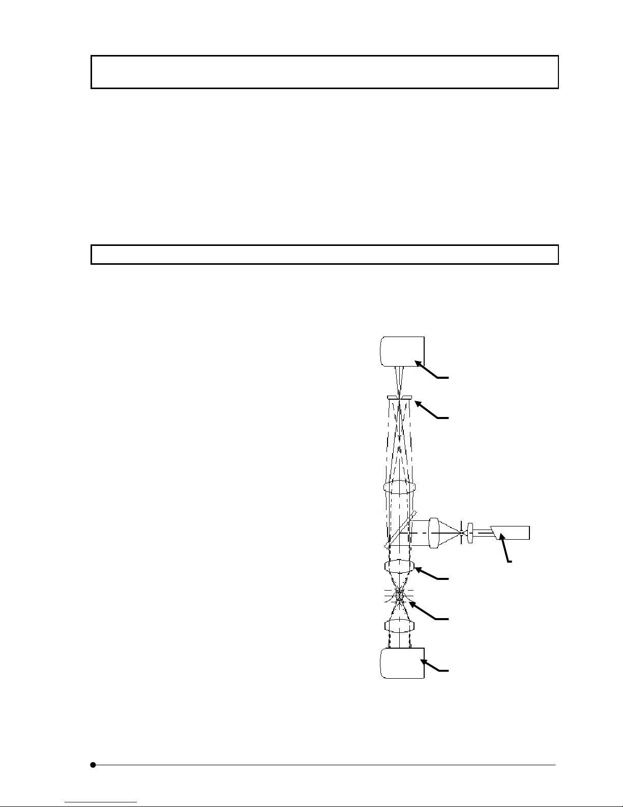
1-1 Principle
A laser-scanning microscope concentrates a laser beam on a very small spot using an
objective and scans the specimen in the X-Y directions.
It then detects the fluorescence and transmitted light from the specimen using light
detector and outputs the image of the
specimen on an image monitor.
The confocal optics place a confocal
aperture at a position which is optically
conjugate with the focusing position (i.e.
confocal plane) in order to eliminate
light from parts other than those for the
focusing position. As a result, the part
corresponding to the eliminated light is
darkened in the image, making it
possible to optically slice a thick tissue
specimen.
On the other hand, with ordinary optical
microscopes, light from a part other
than the focusing position are
overlapped from the image-forming
light on the focusing position, and the
overall image tends to be vague.
Transmitted light images can be
obtained by use of a transmitted light
detector, but the images will not be
confocal image, because there is no
confocal aperture in front of the detector.
The transmitted light image can be used by combination with fluorescence image to
observe fluorescent localization.
Confocal aperture
III .
SYSTEM OVERVIEW
Page
III .
1-1

SYSTEM OVERVIEW/Features of FLUOVIEW FV300
1-2 Features of FLUOVIEW FV300
1. The detector has 12-bit resolution and is capable of detecting very small changes
in fluorescence inside cells.
2. The system has high resolution of a maximum 2048 x 2048 pixels. The output video
signal is non-interlaced to provide a clear image without flickering.
3. The transmitted light is detected by a photomultiplier to offer a bright, sharp
transmitted image.
4. The auto gain adjustment feature eliminates the need for complicated gain
adjustment operation.
5. A total of 3 image channels, including up to 2 fluorescence images and a
transmitted image, can be acquired simultaneously.
6. The confocal aperture can be selected from 5 positions so the optimum confocal
aperture for each objective can be selected with one-touch operation.
7. High-speed scanning acquires 4 images per second (512 x 512 pixels).
8. Sequential scan for acquiring images without crosstalk.
9. In addition to raster scanning, scanning modes such as vector scanning and
oblique scanning are provided to meet a wide range of applications.
10. When using the system with AOTF (FV5-COMBA), the following functions are
available.
x Line Kalman scanning
x Line sequential scanning
x Image acquisition in the REX/Bleach mode(FRAP experiment)
11. One of the two DMs can be selected using the excitation DM selector knob.
12. The ports for introducing the fiber are provided on two positions, that is, on the rear
and left side panels of the scan unit. (The port on the left side panel accepts only
the cable for laser wavelengths of 430 nm or less.)
III .
SYSTEM OVERVIEW
III .
1-2
Page
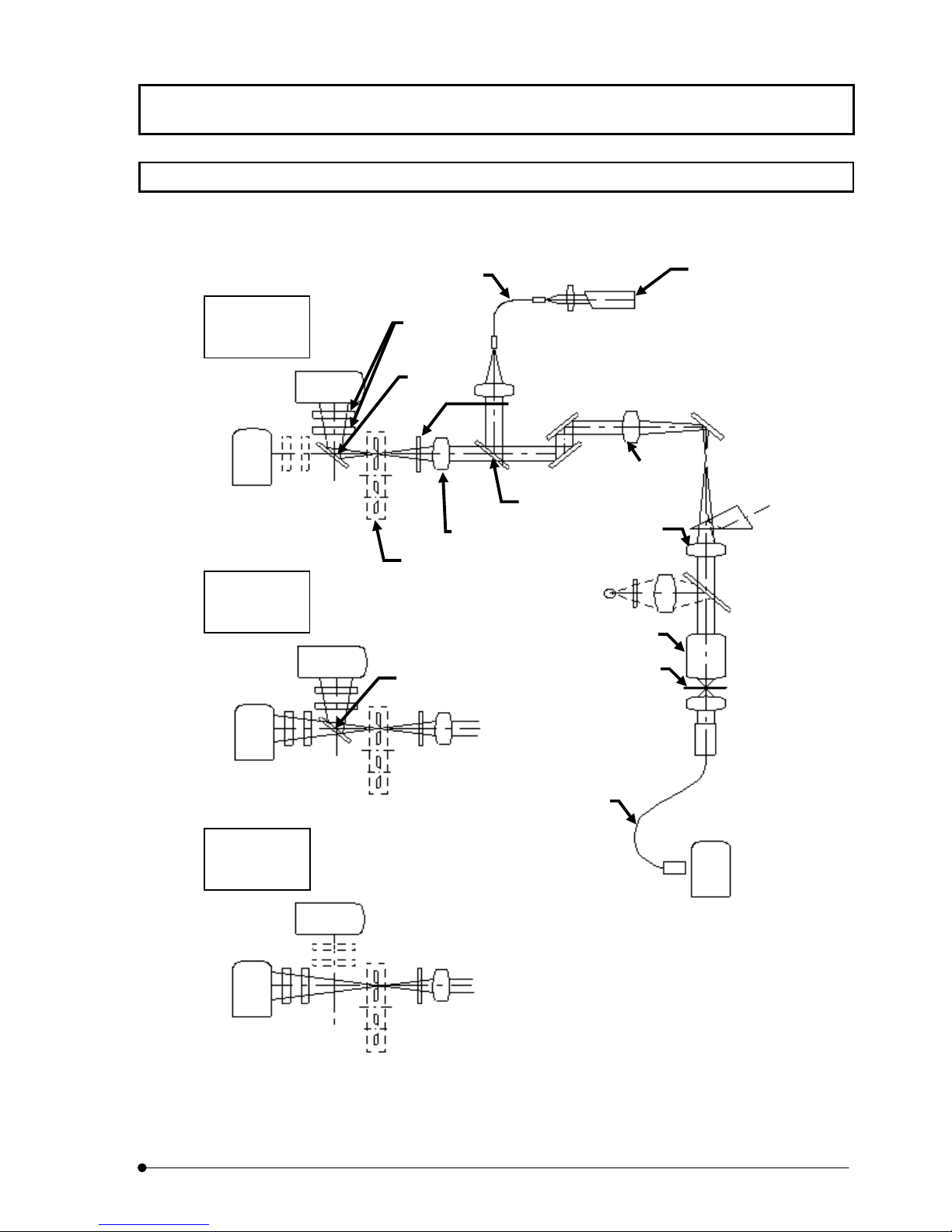
1-3 Light Path Diagram
SYSTEM OVERVIEW/Light Path Diagram
Optical
CH1 CH2
FL ––
CH2 PM2
CH1 CH2
FL FL
CH2 PM2
CH1
PM1
CH1
PM1
Barrier
filters
½
°
¾
Mirror
Condensing lens
Confocal aperture turret
Custom dichroic mirror
for separating the
fluorescence emission
°
¿
Light axis adjustment plate
Beam expander
Pupil
lens
CH1 CH2
–– FL
CH1
PM1
CH2 PM2
Optical
Page
PM3
III .
SYSTEM OVERVIEW
III .
1-3
SYSTEM OVERVIEW/System Configuration
g
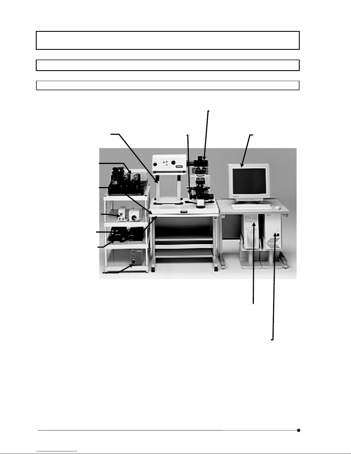
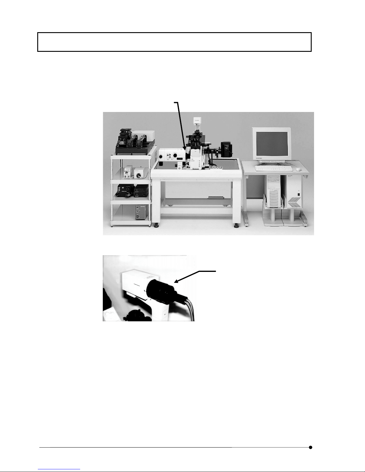
1-4 System Configuration
1-4-1 System Component Units and Their Functions
Upright stand
Support the scan unit.
Protects the
microscope against
excessive load.
Laser Combiner
Unit which compounds
various laser light.
Rubber feet antivibration table
Exclusively designed
platform with rubber
feet.
Transmitted light
detector (optional)
Unit for acquiring
transmitted images.
Upright microscope
frame desk
Laser power supply
unit
Supply power to the
laser oscillator.
Reflected light power
supply unit
Supply power to the
mercury burner light unit.
Z motor
Motor for driving the
focusing adjustment knobs
of the microscope.
Photo 1-1 Combination with BX61
Microscope
BX61 upright microscope
set up for fluorescence
observation.
Image monitor
Video monitor for
displaying laser scanning
images, control panel, etc.
Computer
Used to control the
LSM, process image
files, etc.
III .
SYSTEM OVERVIEW
III .
1-4
Page
Power unit
Control the scanning
unit and converts the
detection signal into
e.
ima
SYSTEM OVERVIEW/System Configuration
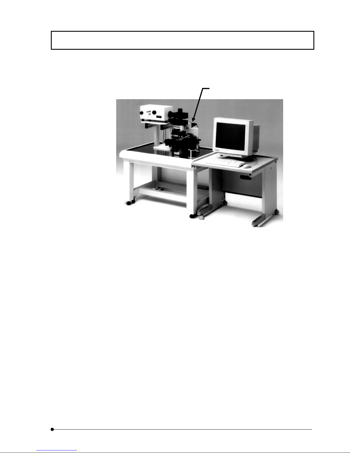
Microscope
BX51WI stage-fixed upright
microscope set up for fluorescence
observation.
Photo 1-2 Combination with BX51WI
Page
III .
SYSTEM OVERVIEW
III .
1-5
SYSTEM OVERVIEW/System Configuration
Microscope
IX81 inverted microscope set up
for fluorescence observation.
Photo 1-3 Combination with IX
Transmitted light detector (optional)
Unit for acquiring transmitted images.
III .
SYSTEM OVERVIEW
III .
1-6
Page
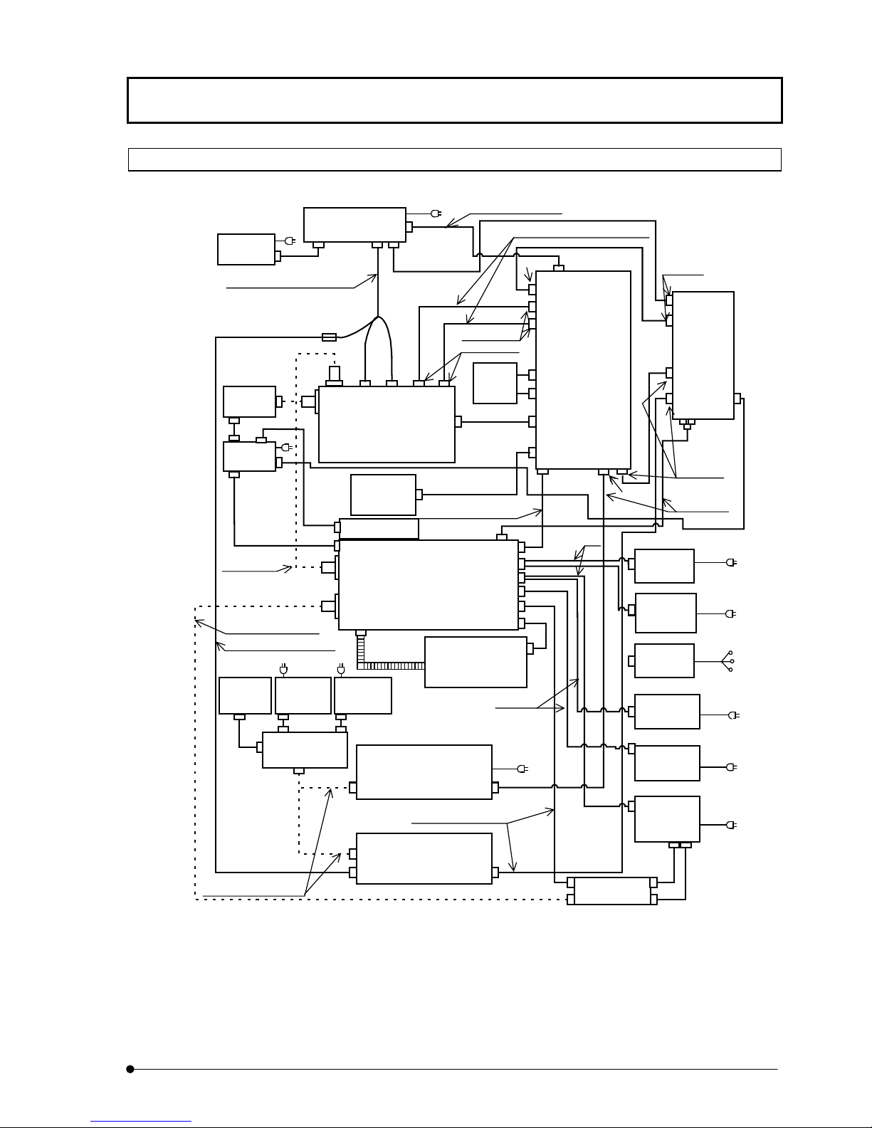
1-4-2 Block Diagram
MONITOR
Analog signal cable 2.9 m
COMPUTER
Dsub15pin
50pin
I/O cable, 2.9 m
SYSTEM OVERVIEW/System Configuration
Galvano control cable
Galvano X/Y cables, 2.9 m each
50pin
1m
50pin
FV5-
LD405
FV5-
LDPSU
Optical fiber cable 3m
Optical fiber cable 3m
Analog signal cable 2.9m
U-MCB
(combination
with AX only)
U-PS
(combination
with AX only)
BNC
BNC
(combination with
BX51, 61 only)
BNC
FV3-SU-3
SCAN UNIT
FV5-ZM
Z MOTOR
FV5-LD440
LASER COMBINER
Duct 2.2 m
BX-UCB
Power control cable
Control cable, 2.9 m
FV5-COMB(2)
Kr LASER SILOCCO
Dsub15pin
Dsub15pin
Warning
SU control
2.9m
FAN
Laser
cable
Dsub9pin
1.8m
FV5-PSU-2
POWER SUPPLY
UNIT
Dsub25pin
Dsub25pin
2m
1m
8pin
Ar LASER
POWER
SUPPLY UNIT
Multiline Ar
LASER
POWER
SUPPLY UNIT
Kr LASER
POWER
SUPPLY UNIT
HeNe (G)
LASER POW ER
SUPPLY UNIT
FV5-LCU
Laser Control
Unit
Circular X2
Dsub25pin
Control cable
2.9 m
5.5m
5.5m
5.5m
1.8m
MICROSCOPE
Optical fiber cables 2 m
LG-PS2
TRANSMITTED LIGHT UNIT
FV5-TD
TRANSMITTED LIGHT
BNC
DETECTOR
Control cable, 2.9 m
Dsub25pin
Dsub25pin
FV5-LUHECD
Either the Kr laser or HeNe(G) laser can be used.
Page
HeNe (R)
LASER POW ER
SUPPLY UNIT
HeNe
LASER
POWER
SUPPLY UNIT
Control
cable
2.2 m
III .
SYSTEM OVERVIEW
1.8m
1.8m
High
voltage
cable
2.2 m
III .
1-7
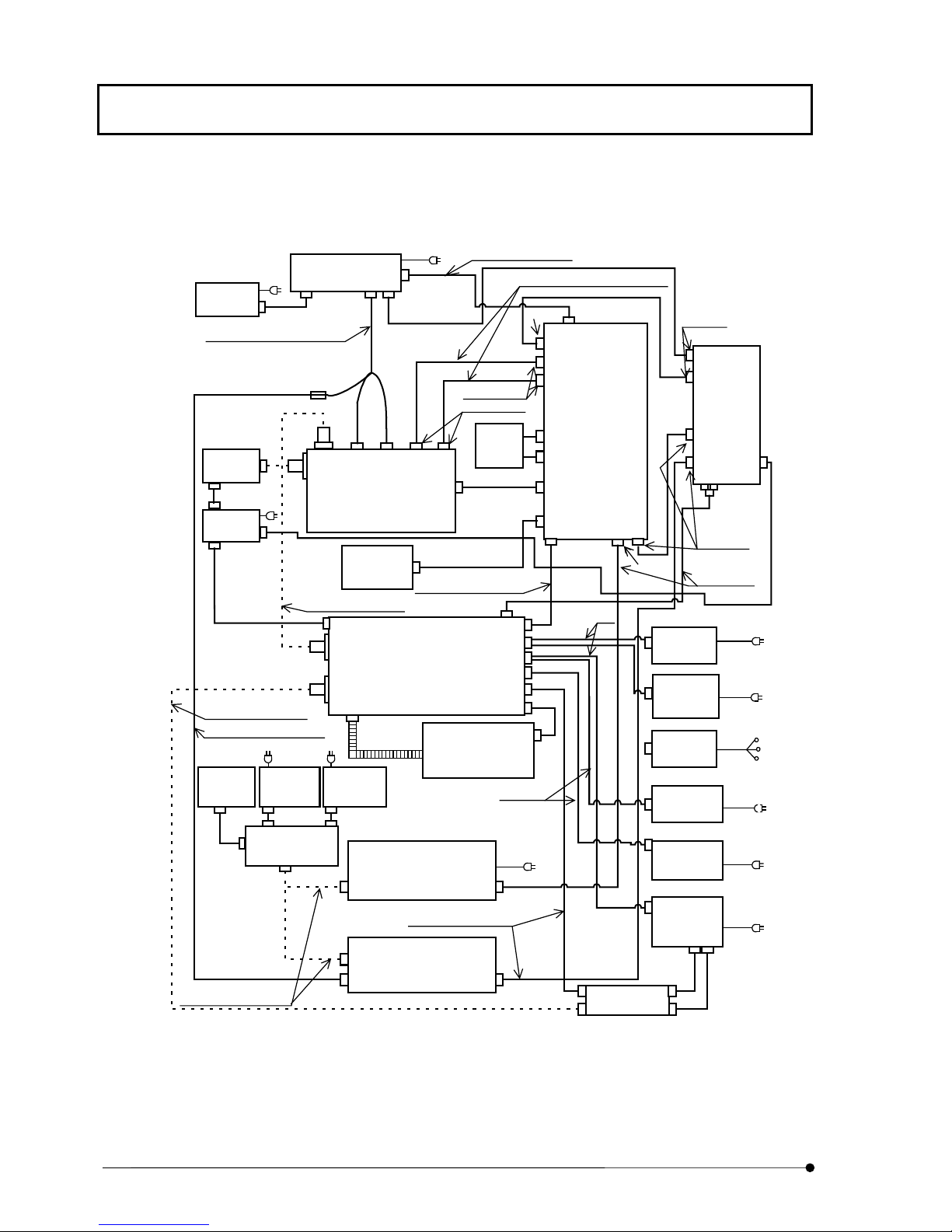
SYSTEM OVERVIEW/System Configuration
The block diagram in AOTF (FV5-COMBA) use.
COMPUTER
MONITOR
Analog signal cable 2.9 m
Dsub15pin
50pin
I/O cable, 2.9 m
Galvano control cable
Galvano X/Y cables, 2.9 m each
50pin
1m
50pin
FV5-
LD405
FV5-
LDPSU
Optical fiber cable 3m
Analog signal cable 2.9m
U-MCB
(combination
with AX only)
U-PS
(combination
with AX onl y)
BNC
BNC
BNC
FV3-SU-3
SCAN UNIT
FV5-ZM
Z MOTOR
Optical fiber cable 3m
LASER COMBINER
Duct 2. 2 m
BX-UCB
(combination with
BX51, 61 only)
Power control cable
Control cable, 2.9 m
FV5-COMBA
with AOTF
Kr LASER SILOCCO
Dsub15pin
Dsub15pin
Warning
SU control
2.9m
FAN
Laser
cable
Dsub9pin
1.8m
FV5-PSU-2
POWER SUPPLY
UNIT
Dsub25pin
Dsub25pin
2m
1m
8pin
Ar LASER
POWER
SUPPLY UNIT
Multiline Ar
LASER
POWER
SUPPLY UNIT
Kr LASER
POWER
SUPPLY UNIT
HeNe (G)
LASER POW ER
SUPPLY UNIT
FV5-LCU
Laser Control
Unit
Circular X2
Dsub25pin
Control cable
2.9 m
5.5m
5.5m
5.5m
1.8m
MICROSCOPE
Optical fiber cables 2 m
III .
SYSTEM OVERVIEW
III .
1-8
Page
BNC
LG-PS2
TRANSMITTED LIGHT UNIT
Control cable, 2.9 m
FV5-TD
TRANSMITTED LIGHT
DETECTOR
Dsub25pin
Dsub25pin
FV5-LUHECD
HeNe (R)
LASER POW ER
SUPPLY UNIT
HeNe
LASER
POWER
SUPPLY UNIT
Control
cable
2.2 m
1.8m
1.8m
High
voltage
cable
2.2 m

For connection to FV5PSU (PC-SYSTEM), 50
pin.
For connection to PC (PCSYSTEM), 50 pin.
Outputs for laser intensity
(Analog, 0-10V)
(VIS1 and VIS2 are for
invisible laser, UV is for UV
laser, IR is for IR laser and
Blanking is for switching laser
ON/OFF.)
(UV laser and IR laser are
optional.)
SYSTEM OVERVIEW/System Configuration
Input and output terminals on FV5-LCU back
VIS1VIS2 UV IR Blanking
VIS1 VIS2 UV IR
For switching signals output
from the left connectors
(VIS1 and VIS2 are for invisible
laser, UV is for UV laser, IR is
for IR laser and Blanking is for
switching laser ON/OFF.)
(UV laser and IR laser are
optional.)
For connection to (AOTF)
FV5-COMBA
(Coaxial connector)
Service connector
For connection to FV5-PSU
(TD)
(Dsub 25 pin, male terminal)
For connection to FV5-TD
(Dsub 25 pin, male terminal)
Event output signal 1 (TLL)
Event output signal 0 (TLL)
Trigger input signal 1 (TTL)
Trigger input signal 0 (TTL)
Horizontal sync signal
(TTL)
Vertical sync signal (TTL)
Page
III .
SYSTEM OVERVIEW
III .
1-9
SYSTEM OVERVIEW/Software Functional Configuration
1-5 Software Functional Configuration
This software uses panel-type windows.
Usually, it is required to “select a menu then select the command to be executed” in
order to execute a function provided by software. With the panel system, a software
function can be executed easily by “selecting the panel page tab of the function to be
executed”, just like when using a system notebook or file folder.
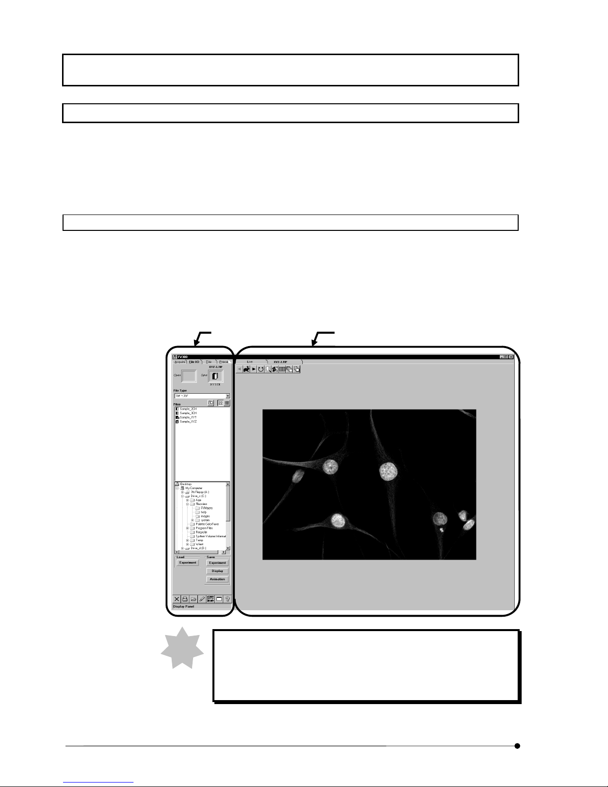
1-5-1 Function Panel and Display Panel
The FLUOVIEW software is organized by two kinds of panels, the function panels and
display panel.
The function panels include the [Acquire], [File I/O], [Tile], [Process], [Analyze] and
[Visualize] panels.
The display panel shows either the [Live] panel or the panel image loaded from a file
([(filename)] panel).
Function panel Display panel
NOTE
III .
SYSTEM OVERVIEW
III .
1-10
Page
In this manual, the function panels are referred to simply using their
page tabs.
Namely, the [File I/O] panel of function panel is referred to simply as
the [File I/O] panel.

1-5-2 Panel Structure of the Software
This software cannot show the page tabs of all function panels at a glance, but uses
scrolling to display the desired page tab. Please use the following list of the panels as
reference in scrolling.
SYSTEM OVERVIEW/Software Functional Configuration
Acquire
Settings
Z Stage
Time Series
Dyes
Lasers
File I/O
Tile
Process
Math
Filters
Histogram
Experiment Editor
Analyze
Single
Series
Visualize
Set up the image acquisition and executes actual acquisition.
Set the observation mode for image acquisition.
Set the reference of a Light path selector knob for image acquisition.
Set the Z-direction scanning range for image acquisition.
Set the interval period for image acquisition.
Set the fluorescence dye for each image channel.
Set the intensity of laser and other option for image acquisition.
Save, load and delete images.
Change the image display method.
Process the acquired images.
Perform mathematical operations between images.
Filter images.
Change the image contrast.
Appends two images, adds and extracts the channel.
Analyze image data.
Obtain the intensity values, intensity distribution, length, area and
average intensity in images.
Obtain the change in the average and sum of intensity values in images.
Construct an image from a different viewpoint or displays a 3D image.
Orientation
Other Opations
Set the image rotation angle, direction and number.
Set the various 3D Rendering.
III .
Page
SYSTEM OVERVIEW
III .
1-11
SYSTEM OVERVIEW/Software Functional Configuration
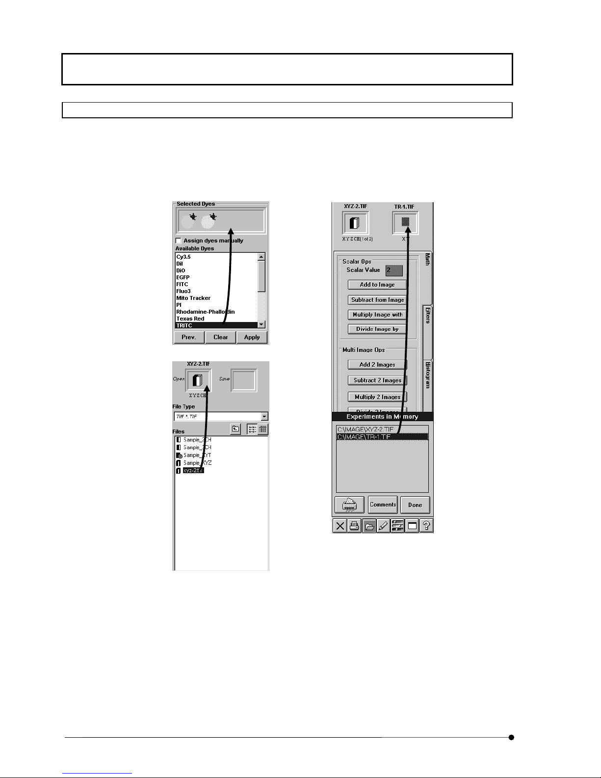
1-5-3 Icons Executed by Dragging & Dropping
This software selects image files and observation methods (dye name) by means of
dragging & dropping. This allows simple selection based on an intuitive operation of
“selecting an icon (image file or observation method), dragging it to the desired position
and dropping it there”.
III .
SYSTEM OVERVIEW
III .
1-12
Page
SYSTEM OVERVIEW/Software Functional Configuration
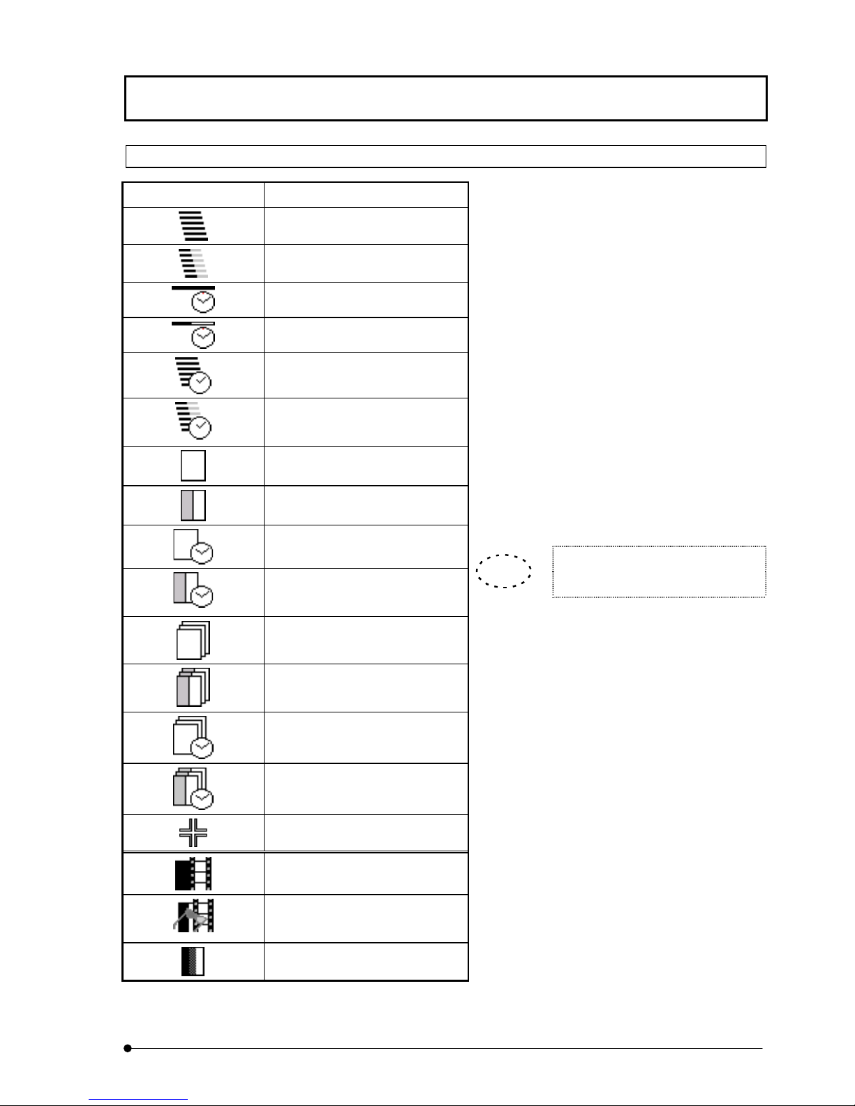
1-5-4 Identification of Images Depending on the Observation Methods
In many occasions, FLUOVIEW displays image
Image Icon Significance
XZ observation
XZ observation, 2-channel mode
Xt observation
Xt observation, 2-channel mode
XZT observation
XZT observation, 2-channel
mode
XY observation
icons to allow identification of the observation
method used when each image is acquired.
(See table on the left.)
When the [File I/O], [Tile], [Process], [Analyze]
or [Visualize] panel is selected, the icon of the
image selected in the [Display] panel is
displayed in a frame at the top of the function
panel. The image icons are also displayed in the
[Icon] field in the [Files] list box in the [File I/O]
panel or during dragging of an image file.
Use these icons to identify the observation
methods used in image acquisition.
XY observation, 2-channel mode
XYt observation
XYt observation, 2-channel
mode
XYZ observation
XYZ observation, 2-channel
mode
XYZt observation
XYZt observation, 2-channel
mode
Point Scan
Animation image
TIP
In all observation modes, the icons
for 3 or more channels are identical.
Stereo 3D image: Image to be
viewed with color eyeglasses.
3 or more channels
Page
III .
SYSTEM OVERVIEW
III .
1-13


V..
IIV
O
O
N
IIN
P
P
S
S
E
R
A
TII
E
R
A
T
R
R
U
U
T
On This Volume
T
C
C
O
O
TII
T
N
N
O
O
N
N
S
S
This volume describes the operating procedures of the
FLUOVIEW FV300 system.
“Getting Started FLUOVIEW” contains information on the basic
operation flow until acquisition of XY images.
“APPLIED OPERATIONS” provides detailed operating procedures
of the system.
Please read this volume so that you can understand the system
before use.


CONTENTS
1 Getting Started FLUOVIEW 1-1
1-1 Basic Operations .............................................................................1-1
1-1-1 Scan Unit .....................................................................................................1-1
1-1-2 Microscope ..................................................................................................1-8
1-1-3 General Mouse Operation Procedures.......................................................1-17
1-1-4 Names of Major Panel and Window Controls and Their Functions.............1-18
1-2 Outline of LSM Observation Procedures..................................... 1-20
1-2-1 Turning Power On......................................................................................1-22
1-2-2 Starting the Software .................................................................................1-26
1-2-3 Focusing on the Specimen.........................................................................1-28
1-2-3-1 Combination with BX........................................................................................1-28
1-2-3-2 Combination with IX .........................................................................................1-29
1-2-4 Setting the LSM Light Path ........................................................................1-31
1-2-4-1 Combination with Upright Microscope (BX) .....................................................1-31
1-2-4-2 Combination with Erected Microscope(AX) .....................................................1-35
1-2-4-3 Combination with Inverted Microscope (IX81) .................................................1-36
1-2-4-4 Combination with Inverted Microscope (IX70) .................................................1-38
1-2-5 Setting the Dyeing Methods .......................................................................1-40
1-2-6 Selecting the CONFOCAL APERTURE .....................................................1-42
1-2-7 Selecting the DETECTION MODE.............................................................1-42
1-2-8 Setting the Barrier filters ............................................................................1-42
1-2-9 Setting the Excitation DM...........................................................................1-45
1-2-10 Setting the ND Filters of the Laser Combiner...........................................1-45
1-2-11 Selecting the Laser Line Filters (Combination Using the Kr/Ar Laser)......1-46
1-2-12 Setting the Observation Condition............................................................1-46
1-2-12-1 Setting the Objective Magnification ................................................................1-46
1-2-12-2 Setting the Zoom Ratio to 1X .........................................................................1-46
1-2-12-3 Setting the Channels......................................................................................1-47
1-2-12-4 Setting the Highest Scan Speed ....................................................................1-48
1-2-12-5 Setting the XY Observation Mode..................................................................1-49
1-2-12-6 Repeated Scanning Operation.......................................................................1-49
1-2-12-7 Setting the Multiple sections to be Observed.................................................1-50
1-2-12-8 Setting the Area to be Observed....................................................................1-51

CONTENTS
1-3 Online Help..................................................................................... 1-57
1-2-12-9 Setting a Lower Scan Speed ......................................................................... 1-51
1-2-12-10 Stopping Repeated Scanning...................................................................... 1-52
1-2-13 Adjusting the Detection Light Axis............................................................1-52
1-2-14 Acquiring Image.......................................................................................1-52
1-2-15 Saving Image...........................................................................................1-54
1-2-16 Exiting from the Software.........................................................................1-55
1-2-17 Turning Power Off....................................................................................1-56
1-3-1 Referencing Method...................................................................................1-57
1-3-2 Setup of Microscope and Scan Unit ...........................................................1-58
1-3-2-1 Configuring the Microscope............................................................................. 1-61
1-3-2-2 Configuring the Scan Unit ............................................................................... 1-63
1-3-2-3 Configuring the Filters ..................................................................................... 1-64
1-3-2-4 Configuring the Microscope (Combination with BX51, BX61, IX81) ............... 1-66
1-3-2-5 Parfocality Correction and Jog Sensitivity Adjustment (When the BX or IX is
used)................................................................................................................ 1-72
2 APPLIED OPERATIONS 2-1
2-1 General Operation Procedure......................................................... 2-1
2-1-1 Image Acquisition Procedure (Section (A)) ..................................................2-3
2-1-2 Image Acquisition Procedure in an Observation Mode (Section (B))............2-4
2-1-3 Examples of Operation Procedures .............................................................2-5
2-2 Image Acquisition............................................................................ 2-7
2-2-1 Image Acquisition in XY Observation Mode .................................................2-8
2-2-1-1 Configuring the Microscope............................................................................... 2-9
2-2-1-2 Configuring the Scan Unit ............................................................................... 2-13
2-2-1-3 Setting the Observation Condition................................................................... 2-14
2-2-1-4 Acquiring Image .............................................................................................. 2-22
2-2-1-5 Acquiring Image in Accumulation Mode.......................................................... 2-22
2-2-1-6 Saving the Acquired Image in File................................................................... 2-26
2-2-2 Image Acquisition in Other Observation Modes .........................................2-27
2-2-2-1 XZ Observation Mode ..................................................................................... 2-27
2-2-2-2 XT Observation Mode ..................................................................................... 2-33
2-2-2-3 XZT Observation Mode ................................................................................... 2-35
 Loading...