

Olympus Fluoview-1000 User Manual

Olympus Fluoview-1000 User’s Guide
V.M. Bloedel Hearing Research Center, Core for Communication Research
Center on Human Development and Disability, Digital Microscopy Center
Quick Start Guide
Start-Up 5
Shut-Down 5
............................................................................................................Quick Guide to Getting an Image 6
........................................................................................................Place the sample on the microscope 7
........................................................................................Finding the sample – transmitted light or DIC 7
..................................................................................................................................Brightfield vs. DIC 9
....................................................................................................Finding the sample – epi-fluorescence 9
................................................................................................................Finding the sample - confocal 10
......................................................................................................Setting Up for Confocal Microscopy 11
...................................................................................................................................Choosing the Dye 11
..............................................................................................................Changing the Dye Selection 12
...............................................................................................................Confocal acquisition controls. 12
.................................................................................................Settings for the fluorescence detectors. 13
.................................................................................................................Additional detector controls. 13
.......................................................................................................................................Laser Controls. 14
...................................................................................................................................Line Selection. 14
..............................................................................................................Line availability, Figure 7.2. 14
......................................................................................................Laser Power Selector, Figure 7.3. 15
.......................................................................................................................Scroll List, Figure 7.4. 15
....................................................................................................................Line Settings, Figure 7.5 15
.........................................................................................................................................Scan Controls 16
...........................................................................................................................Scan Mode, Figure 6.1 16
..........................................................................................................................Dwell Time, Figure 6.2 16
..................................................................................................................Scan Regions, Figure 6.3. 17
........................................................................................................Image Aspect Ratio, Figure 6.4. 17
.....................................................................................................................................Box Size, 6.5. 17
.............................................................................................................Box Size effect on resolution 18
......................................................................................................................................AutoHV, 6.6. 18
................................................................................................................................Scan Area Controls 18
..................................................................................................................................Field of View, 8.1. 18
.......................................................................................................................................Scan Area, 8.2. 18
.................................................................................................................................Scan Rotation, 8.3. 18
.....................................................................................................................................Scan Zoom, 8.4. 19
..........................................................................................................................Reset Scan Values, 8.5. 19
.....................................................................................................................................Scan Offset, 8.6. 19
..............................................................................Use of Sequential, Simultaneous and Averaging. 21
................................................................................Simultaneous Capture versus Sequential Capture. 21
....................................................................................................Two Methods for Sequential Capture 21
..................................................................................................Sequential Line Capture, Figure 9.1 21
...............................................................................................Sequential Frame Capture, Figure 9.1 21
May 11, 2011 1

Olympus Fluoview-1000 User’s Guide
V.M. Bloedel Hearing Research Center, Core for Communication Research
Center on Human Development and Disability, Digital Microscopy Center
.....................................................................................................Scan mode and sequential capture 22
.......................................................................................................Using Channel Groups, Figure 9A. 22
....................................................................................Adjusting the channels with sequential imaging 22
...............................................................................Adjusting the channels with simultaneous imaging 22
...............................................................................................................................Collecting a Z-Series. 23
...........................................................................................Determine the depth of the optical volume. 23
..........................................................................................................Which way does the focus move? 23
..............................................................................................................Settings for z-series collection. 25
........................................................................................................................What is axial resolution? 25
...................................................................................................................................Vertical Sections. 26
...............................................................................................................Files: Saving and Transferring 26
...........................................................................................................................................Saving Files 26
.............................................................................................................The Olympus “OIB” format. 26
..............................................................................................................The Olympus “OIF” format. 26
.............................................................................................Where are Your Files on the Confocal? 27
....................................................................................................................................Export file types. 27
................................................................................................................Add a scale bar to your file 27
...............................................................................................................................Opening your Files. 27
.......................................................................................................................Olympus free file viewer 28
................................................................................................................Offline Fluoview workstation 28
.............................................................................................Importing Olympus datasets into ImageJ. 28
............................................................................................................Loci-tools Plugin for ImageJ. 28
...........................................................................................................Import Channel Order Macro. 28
...............................................................................................................................Image 5D plugin. 28
..........................................................................................File Import from the OIF.Files directory. 29
..........................................................................................................................................File Transfer. 29
.................................................................File transfer to Mac Pro ‘Fluoview’, confocal file server. 29
.....................................................................................Saving files directly to Mac Pro ‘Fluoview’. 29
..........................................................................................USB and Firewire Ports on the Mac Pro. 29
................................................................Recording to CD-ROM and DVD-ROM on the Mac Pro. 30
............................................Networked file transfer to remote servers from the Fluoview Mac Pro 30
....................................................................................................Using FTP to Windows computers 30
........................................................................Remote access to the Mac Pro from your laboratory. 30
..................................................................................................................Optimizing Image Collection 31
..............................................................................................Qualities of an Optimal Confocal Image. 31
...............................................................................................Overview of image capture properties 31
.........................................................................................................Overview of basic image capture. 31
.............................................................................................Basic settings for confocal microscopy 31
.................................................................................................................................Labeling Controls. 32
...............................................................................................................................Negative controls 32
................................................................................................................................Positive controls 32
............................................................................................................................The confocal aperture 32
........................................................................................................................Optimal Iris Diameter 32
May 11, 2011 2

Olympus Fluoview-1000 User’s Guide
V.M. Bloedel Hearing Research Center, Core for Communication Research
Center on Human Development and Disability, Digital Microscopy Center
.........................................................................................................................................Bleedthrough. 33
......................................................................................................................Reducing bleedthrough 33
.................................................................................................Procedure to minimize bleedthrough 33
.....................................................................................................................................................Noise. 34
................................................................................................................Signal Noise (Shot Noise). 34
..................................................................................................................................Detector Noise. 35
............................................................................................................................Kalman Averaging. 35
............................................................................................................................................Background 35
.....................................................................................Bright Images versus Scorching the Specimen 35
.....................................................................................................................Images with Weak Signals 35
...........................................................................................................................................Using Zoom 36
..........................................................................................Zoom reduces objective lens aberrations. 36
..........................................................Use Zoom to fulfill sampling requirements for the specimen. 36
.......................................................................Use Zoom to fulfill adequately sample the objective. 36
.............................................................................................................................Obtaining a Z-Series. 37
.............................................................................................................................................Resolution. 37
................................................................................Sampling frequency and the Nyquist Theorem. 38
............................................................................................................................................Box size. 38
Zoom. 38
..........................................................................................Considerations for increasing resolution. 38
.........................................................................................................................................Size of Pixels 39
..........................................Table. 5 Pixel Size (µm) versus Box Size and Magnification at Zoom = 1 39
................................................................................................................................Microscope controls. 41
.....................................................................................................................................................Focus. 41
............................................................................................................................Fine/Coarse Focus. 41
...................................................................................................................Lowering the Objectives. 41
..................................................................................................................................Manual shutter. 41
..............................................................................................Differential Interference Contrast (DIC). 41
....................................................................................................................................DIC Analyzer. 41
....................................................................................................................................DIC polarizer. 42
........................................................................................................................................DIC mirror. 42
................................................................................................................Setting Koehler Illumination. 42
...........................................................................................................................Condenser position. 43
........................................................................................................................Photoactivation Methods. 44
.....................................................................................................................Zoom versus Laser Power. 44
...........................................................................................................Recording initial recovery event. 44
..........................................................................................................Methods to photoactivate/bleach. 44
.............................................................................................................Using the Stimulus Window. 44
..................................................................................................Avoid spontaneous photoactivation. 46
...........................................................................................Controlling Computer Display Brightness. 46
..................................................................................................................Set ‘Darkroom’ color mode. 47
.............................................................................................................................Technical Information 48
.............................................................................................................................Caring for Objectives 48
May 11, 2011 3

Olympus Fluoview-1000 User’s Guide
V.M. Bloedel Hearing Research Center, Core for Communication Research
Center on Human Development and Disability, Digital Microscopy Center
.............................................................................................................FV-1000 Optical Specifications 48
.................................................................................................................................................No Image! 50
..................................................................................................................................Start-up problems. 50
..............................................................................................................................Scans, but no image. 50
..............................................................................The confocal image appears unevenly illuminated: 50
...................................................The epifluorescent or tungsten images appear unevenly illuminated: 50
Figures
Figure 1. Main Fluoview window. 6
Figure 2. Enlarged view of Fluoview windows. 8
Figure 3. Microscope Controller Window 9
Figure 4. Image Acquisition Window – Basic controls for Finding the Image 11
Figure 5. Channel Settings for the Photomultiplier Tube (PMT) 14
Figure 6. The Scan Mode and Scan Size settings of the Acquisition Setting Window. 16
Figure 7. Selecting laser lines and setting laser power 15
Figure 8. Scan Controls for Zoom, Pan and Rotation 19
Figure 9. Sequential Imaging Control 20
Figure 9A. Sequential Imaging Control 20
Figure 10. Z-Series Control Window 24
Figure 11. Z-Series Control Window 24
Figure 12. DIC and Focus Controls, Lower Half of the Microscope 40
Figure 13. Condenser and DIC Controls 42
Figure 14. Tilting the condenser. 43
Figure 15. The Stimulus Setting window for photoactivation 45
Figure 16. Photobleaching an ROI. 46
Figure 17. The toolbar item for control over display color 47
Figure 18. Fluoview appearance in Darkroom Color 47
Table 1. Mirror Buttons 10
Table 2. Objective Lenses Available 12
Table 3. Scan Speed and Acquisition Time 14
Table 4. Optimal Z-Step Values 37
Table 5. Pixel Size (µm) versus Box Size and Magnification at Zoom = 1 39
Table 6. Dichroic Mirrors and Barrier Filters 38
Table 7. Laser Lines on the FV-1000 38
Table 8. Index of Refraction for Common Mounting Materials 49
May 11, 2011 4
Tables

Olympus Fluoview-1000 User’s Guide
V.M. Bloedel Hearing Research Center, Core for Communication Research
Center on Human Development and Disability, Digital Microscopy Center
Quick Start Guide
A. Start-up:
All items are lettered in the order in which they are to be turned on.
1. Enter your name and session into the Olympus FV-1000 web calendar;
2. Turn on items labeled with letters:
(A) Turn on mercury lamp, if needed - power supply is on shelf over monitor;
(B) Turn on system controllers – press black switch on power supply on right side of air table, next
to the computer.
(C) Turn on power to lasers – press the switch on power strip under shelf behind confocal (beneath
the lasers) (405 nm, 561 nm, 633 nm);
(D) Fire up the DPSS laser (561 nm) – press the green button;
(E) Turn on Argon ion laser – turn the key to “ON” (458 nm, 488 nm, 514 nm);
(F) Turn on computer, black tower to right of confocal, press round button to right of floppy;
a. Windows user name is “Administrator”
b. password is “fluoview”
3. Double-click on the Fluoview icon, left side of computer monitor desktop, “FV-10ASW”;
4. Choose your name from the users list and enter your password;
NOTE: Fluoview user accounts open with the last settings used by the previous user.
B. Shut down:
1. Transfer files from your account (See File Transfer, Section );
2. Exit from Fluoview;
3. Ignore the warning about light coming through the microscope.
4. Turn off power strip (B);
5. Turn off power strip (C);
6. Turn off argon ion laser (E), key only;
7. Delete images from the hard drive;
8. Turn off the computer;
9. Remove immersion oil from objectives, clean the stage and platform.
10. Edit time in the web calendar, if you went longer than reserved.
Keys versus Switches.
Use the key to turn the argon laser on and off. Do not use the power switch – that will prevent the fan to
run during cooling down and potentially damage the laser.
For components controlled by power strips (B, C, D), do not fiddle with the keys or switches on the
actual components. The exception is that the 561 nm laser (D) needs its green button pushed to turn it
on, but it is turned off by the power strip (C), along with the other 2 lasers.
If the building power fails, backup batteries will provide about 10 minutes to turn off all components.
May 11, 2011 5
Olympus Fluoview-1000 User’s Guide
V.M. Bloedel Hearing Research Center, Core for Communication Research
Center on Human Development and Disability, Digital Microscopy Center
1. Quick Guide to Getting an Image
Examples of the software control windows are on the following pages. The text contains numbers that
refer to specific numbered controls in figures.
Your overall goal with fluorescent microscopy is to image the specimen with the least amount of
photobleaching. This requires limiting specimen exposure to damaging levels of excitation light.
1. Find the specimen using the eyepieces and epi-fluorecence. This is faster than scanning.
2. Low magnification objectives allow rapidly searching over large areas, but usually dimmer.
3. Low intensity transmitted light is safest for finding and positioning the sample.
4. DIC is usually better than brightfield for low contrast samples, such as monolayers or picking out
structures in complex specimens.
5. Epi-fluorescence is usually faster than confocal to find the fluorescent sample.
6. Epi-fluorescence allows you to see a blurry glow from out of focus objects, unlike confocal.
7. Use the least amount of light necessary to find the sample to reduce photobleaching and toxicity.
8. Begin confocal imaging using low laser intensity with high PMT HV while surveying the
sample.
9. Focusing on the edge of the coverslip by transmitted light can help to find initial focus.
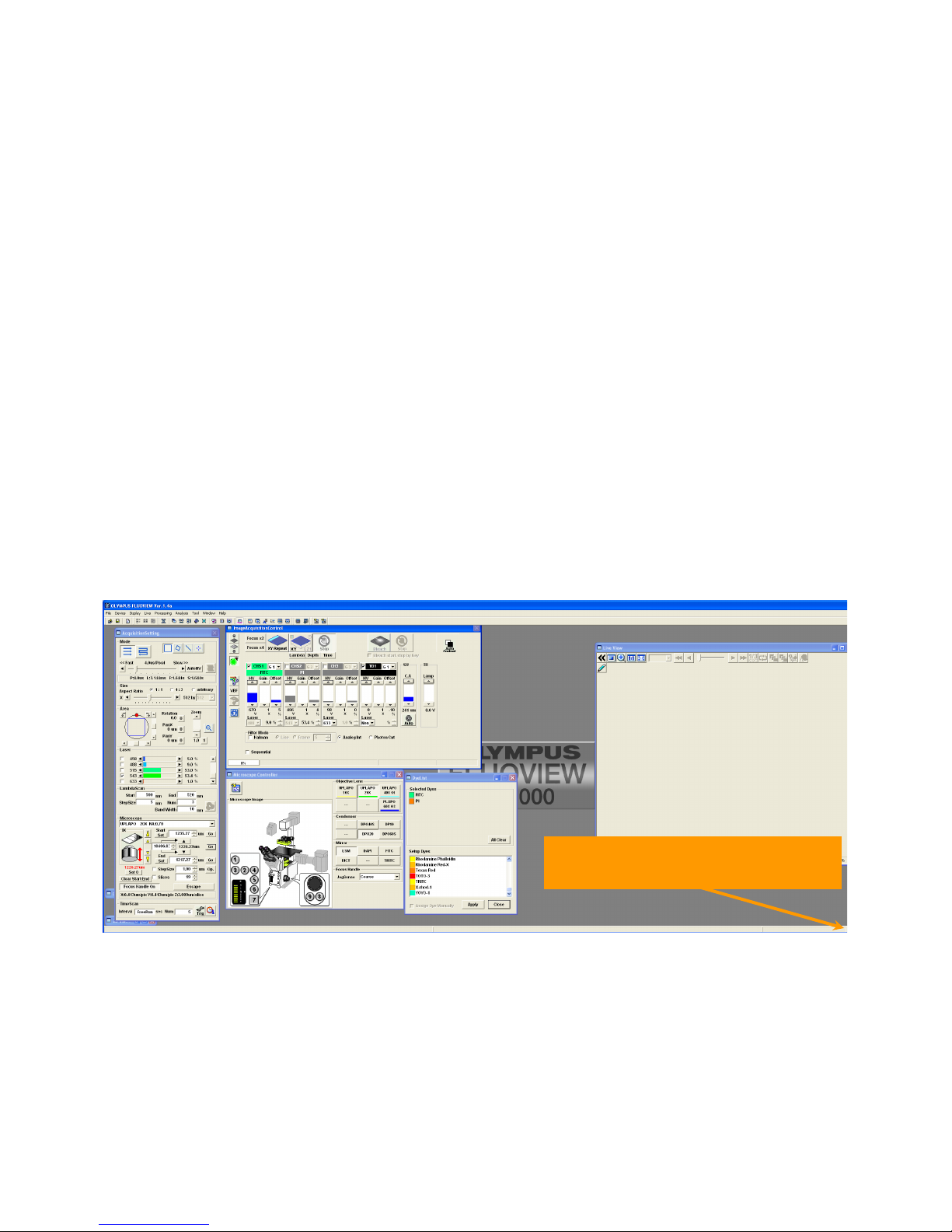
Figure 1. Main Fluoview window.
May 11, 2011 6
Drag this corner to resize the window

Olympus Fluoview-1000 User’s Guide
V.M. Bloedel Hearing Research Center, Core for Communication Research
Center on Human Development and Disability, Digital Microscopy Center
1.1 Place the sample on the microscope
1. Make sure the objective lens is not extending above the level of the specimen holder;
a. If it is, rotate the focus knob to lower the objective lens (set to Coarse Focus)
2. Press ‘ESC’ button behind either focus knob to lower the objectives;
3. Move the condenser up, out of your way;
4. Install the appropriate specimen holder in the stage, if needed;
5. Place the slide on the stage with the coverslip downwards;
6. The sample should be centered in the stage opening to avoid bumping the sample holder with the
lens as you move the stage to position the desired field of interest;
7. Press ‘ESC’ button to return the lens to focus;
8. Lower the condenser back into position;
9. Do not use the keypad on the front of the microscope, it has been disabled;
10. All microscope control must be through the Fluoview software windows, Figures 2, 3;
11. Open the Microscope Controller window, if it is not open: Fluoview
menu>Device>Microscope Controller…, Figure 2.1;
12. Select an objective: Microscope Controller Window>Objective Lens>click on desired lens,
Figures 2.4 and 3.2, see Table 2;
13. Condenser setting: Microscope Controller Window>Condenser sets condenser automatically –
don’t touch, Fig. 3.1;
14. Select mirrors (fluorescence filter cubes): Microscope Controller Window>Mirror>click on
desired mirror, Fig. 3.3, see Table 1;
15. Fine focus/coarse focus: press the ‘F/C’ button below each focus knob, Figure 12.2, to toggle
between focus modes;
16. Lower/raise lens to apply immersion oil: press the ‘ESC’ button behind each focus knob, Figure
12.3;
17. Center the region of interest in the field of view with the joystick;
1.2 Finding the sample – transmitted light or DIC
1. Center the sample over the stage opening to avoid bumping the stage with the lens;
2. Refer to Microscope Controls, Sections 7.2 and 7.3, for details on using DIC and setting Koehler
illumination;
3. Open the Microscope Controller window, Fluoview menu>Device>Microscope Controller…,
Figure 2.1;
4. All microscope control must be through the Fluoview software windows, Figures 2.1, 2.4;
a. Select lens: Microscope Controller Window>Objective Lens, Figure 3.2, Table 2;
b. Condenser controls are set automatically: Microscope Controller Window>Condenser –
don’t touch, Fig. 3.1;
c. DIC condenser settings are automatically selected when transmitted lamp is on:
Microscope Controller Window>Mirror>Select DIC (DICT), Fig. 3.3;
5. Turn on the transmitted light;
May 11, 2011 7

Olympus Fluoview-1000 User’s Guide
V.M. Bloedel Hearing Research Center, Core for Communication Research
Center on Human Development and Disability, Digital Microscopy Center
a. Image Acquisition Control Window>Click on transmitted light, Figure 4.1;
b. Image Acquisition Control Window>adjust brightness (TR Lamp) (click or scroll),
Figure 4.4;
6. Bring sample into focus;
7. Set Koehler illumination [optional, Section 7.3];
8. Center the region of interest in the field of view;
9. Turn off the transmitted light with the Image Acquisition Control Window, Figure 4.1;
10. Switch to fluorescent imaging.
Remove the DIC analyzer from the light path for optimal confocal images!
2.1 Menus
2.2 Acquisition settings
2.3 Image acquisition
2.4 Microscope controller
Figure 2. Enlarged view of Fluoview windows.
May 11, 2011 8
2.5 Dye list window
Olympus Fluoview-1000 User’s Guide
V.M. Bloedel Hearing Research Center, Core for Communication Research
Center on Human Development and Disability, Digital Microscopy Center
1.3 Brightfield vs. DIC
The default setting for plain brightfield imaging is with the condenser DIC prism in place, “DICT”.
True brightfield illumination is obtained by removing the condenser polarizer and analyzer from the
light path then selecting a “--“ setting for the condenser in the Microscope Controller window.
Refer to section 7 for more information.
1.4 Finding the sample – epi-fluorescence
1. Sample should be brought into focus and centered, as described above;
2. Open the fluorescent shutter
a. Image Acquisition Control Window>Click on the fluorescent shutter button, Fig. 4.2;
b. The Microscope Controller will switch to the last filter used;
3. Select fluorescence filter, if desired
a. Microscope Controller Window>Mirror>click on ‘DAPI’, ‘FITC’ or ‘TRITC’ (blue,
green or red fluorescence), Fig. 3.3, Table 1;
4. Adjust focus and stage to position sample;
5. Adjust fluorescent intensity with the aperture lever on the mercury lamp;
6. Close the mercury lamp shutter
a. Image Acquisition Control Window, Fig. 4.2;
b. System will switch to ‘LSM’;
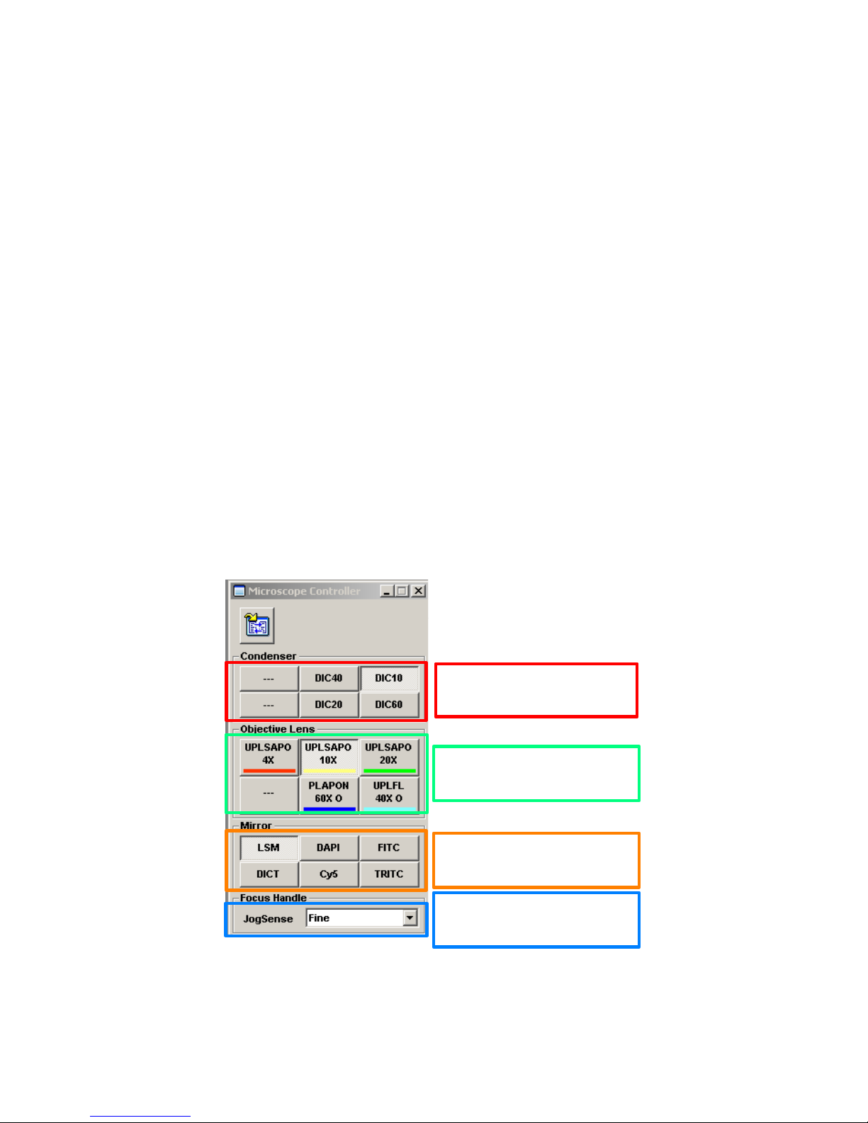
Figure 3. Microscope Controller Window
May 11, 2011 9
3.1 Condenser buttons
[automatic, don’t touch]
3.2 Click on buttons to
select objectives
3.3 Mirror buttons control
imaging mode and filters
3.4 Indicate & toggle
coarse/fine focus

Mirror Button
Function
Mode
Visualization
LSM
Confocal Imaging
Confocal
Confocal only, automatic
DAPI
UV excitation
Epi-fluorescence
Eyepieces only
FITC
Blue excitation
Epi-fluorescence
Eyepieces only
TRITC
Green excitation
Epi-fluorescence
Eyepieces only
Cy5
Red excitation
Epi-fluorescence
Eyepieces or Camera
DICT
DIC/ Brightfield
Transmitted light
Confocal or Eyepieces
---
Brightfield
Transmitted light
Confocal or Eyepieces
Olympus Fluoview-1000 User’s Guide
V.M. Bloedel Hearing Research Center, Core for Communication Research
Center on Human Development and Disability, Digital Microscopy Center
Table 1. Mirror Buttons
1.5 Finding the sample - confocal
1. Select the dyes from the Dye List Window (Section 2.1);
2. Set collection parameters for minimal photobleaching – See “Optimizing Image Collection”;
a. Minimal laser intensity, Acquisition Setting Window>Lasers, Fig. 7, start with 1%;
b. set detector HV fairly high ~1000 V, Image Acquisition Control Window (See section
2.7.1 regarding Auto HV)
3. Set the Live View to tile view, each channel is displayed in a separate window;
4. Set to gray scale (control-h);
5. Set scanning to simultaneous (Sequential checkbox, Fig. 4.9, is cleared);
6. Initiate scanning: Image Acquisition Control Window>Focus X2 or Focus X4, Fig. 4.5;
7. Adjust focus and position of sample;
8. Roughly adjust laser power and HV to reduce saturation;
9. Stop scanning, Image Acquisition Control Window>Stop Fig. 4.8.
10. Refer to Section 2 for more information on settings.
11. Select Sequential, Frame, Fig. 4.9;
12. Select each channel and adjust to minimal laser power and HV less than 750 to avoid saturation
(red masked pixels);
13. Set the Offset to see only a few or no pixels of intensity = 0 (blue masked pixels)
14. Set the dwell time, 2 or 4 µs are good starting points
a. Acquisition Setting Window>Fast-Slow slider, Fig. 6.2;
15. Scan XY Repeat, Image Acquisition Control Window, Fig. 4.6 to preview full resolution;
May 11, 2011 10
Olympus Fluoview-1000 User’s Guide
V.M. Bloedel Hearing Research Center, Core for Communication Research
Center on Human Development and Disability, Digital Microscopy Center
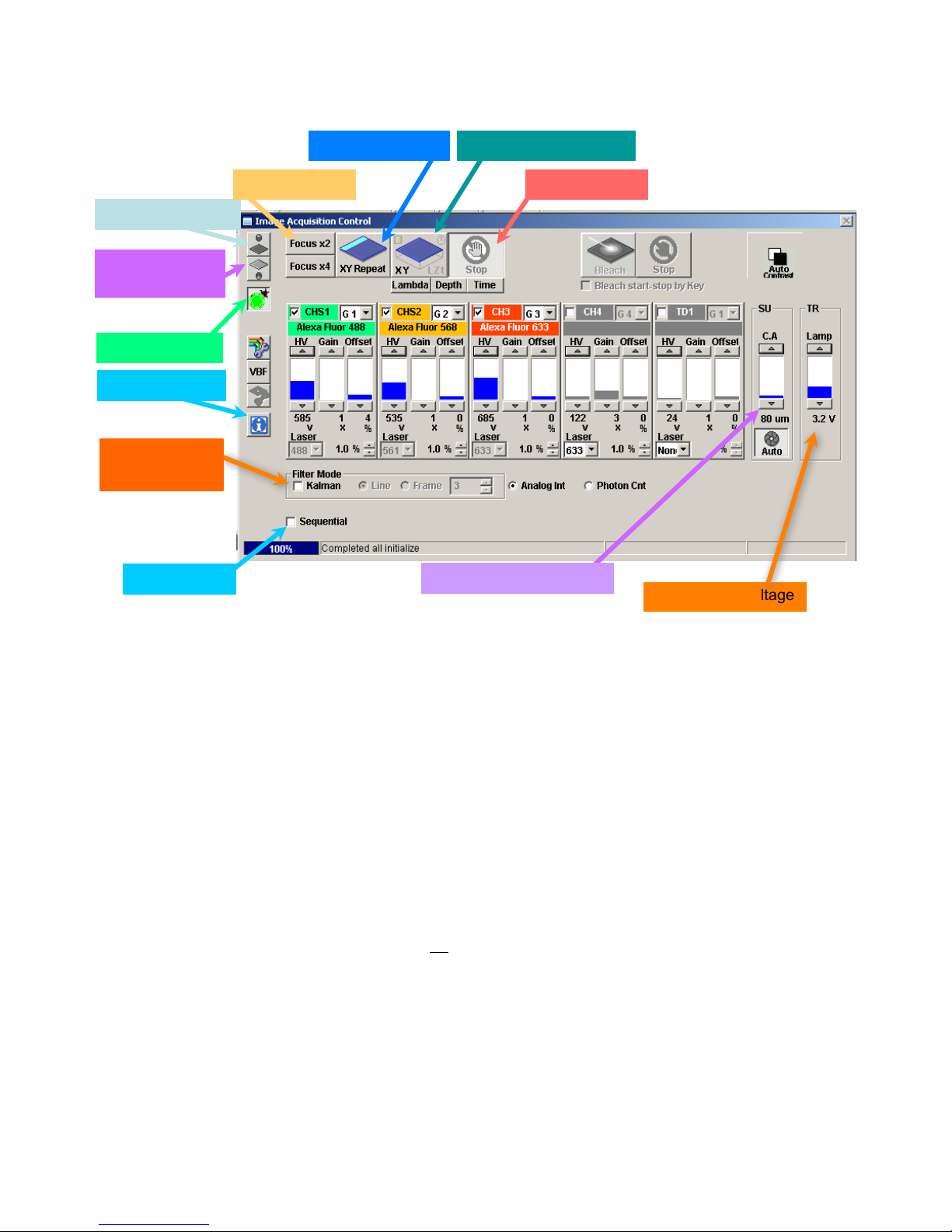
4.1 Tungsten Lamp
4.2 Fluorescence
shutter
4.3 Dye List
4.12 Information
4.11 Kalman
Averaging
4.9 Sequential
4.6 XY Repeat
4.5 Fast scan
4.7 Acquisition scan
4.8 Stop scan
4.10 Confocal Aperture
4.4 Tungsten Voltage
Figure 4. Image Acquisition Window – Basic controls for Finding the Image
2. Setting Up for Confocal Microscopy
This section covers basic settings for obtaining a confocal image.
2.1 Choosing the Dye
Each combination of fluorescent labels requires specific laser lines, dichroic mirrors and filters. These
are selected automatically when you choose the fluorophores from the list in the Dye List Window.
1. Open the Dye List Window, if it is not currently visible, Fig. 2.5;
a. click on Image Acquisition Control/Dye List button, Fig. 4.3, to open;
2. Selected Dyes – upper window displays the currently selected dyes
a. click on “All Clear” to remove all current selections
b. double-click on any selected dye to remove it
3. Scroll through the list of dyes in the lower window;
4. Select each desired fluorophore by double-clicking on the name;
a. if your particular dye does not appear in the list, contact facility manager, or choose one
with similar characteristics
b. dyes with conflicting optical requirements will generate an error message
5. Activate the settings by clicking on the “Apply” button, lower window;
May 11, 2011 11

Olympus Fluoview-1000 User’s Guide
Objective
NA
Working
Immersion
Resolution
Objective
NA
Working
Distance
Immersion
Lateral
Axial
4X UplanSApo
0.16
13 mm
Air
1.906 µm
54.3
10X UplanSApo
0.40
3.1 mm
Air
0.601 µm
8.56
20X LWD*
0.45
7.8 mm
Air
0.677 µm
3.56
20X UPlanSApo
0.75
600 µm
Air
0.319 µm
2.12
40X UPlanFL N
1.30
200 µm
Oil immersion
0.181 µm
0.948
60X PlanSApo
1.35
150 µm
Oil immersion
0.226 µm
0.782
60X/W collar*
1.20
280 µm
Water immersion
0.254 µm
0.800
100X UPlanSApo
1.40
139 µm
Oil immersion
0.168 µm
0.778
V.M. Bloedel Hearing Research Center, Core for Communication Research
Center on Human Development and Disability, Digital Microscopy Center
Dye names are written into the image file metadata. However, fluorophores with broadly similar
excitation and emission spectra will use the same laser line and filters. For example, FITC, EGFP,
Alexa488 and Mitotracker Green will all use the 488 nm laser and a bandpass filter of 500 nm to 550 nm
2.1.1 Changing the Dye Selection
1. Remove a selected fluorophore by double-clicking on the dye name
2. To add a dye
a. double-click on the new label from the dye list
b. set the detectors for the new dye by clicking on “Apply”.
Q. My fluorescent stain is not on the list – what do I do? Refer to “Optimizing the Image”.
Table 2. Objective Lenses Available
*Special purpose, not usually kept on microscope.
*Correction collar allows correction for coverslip thickness and refractive index mis-match.
20X LWD is intended for use with plastic culture dishes.
60X/W lens is used for live tissue or fixed tissue mounted in low RI media such as PBS
2.2 Confocal acquisition controls.
1. Focus X2, 4.5 - Scans only the odd lines and replicates them, at 2 µs pixel dwell time.
a. rapidly scanning is very helpful when focusing and moving the stage.
b. may be used for recording rapid fluorescence changes, such as ion measurements.
2. Focus X4, 4.5 - Scans alternate odd lines, replicating the scanned lines to generate an image of
4X reduced resolution in the Y-axis, at 2 µs pixel dwell time for extremely fast scanning.
3. XY Repeat, 4.6 – Scans at full resolution, at the user’s chosen dwell time.
4. XY, 4.7 – Acquires one image, or defined set of images, using the current settings.
5. Stop, 4.8 – Stops any scan, retaining the current image in the Live Image Window.
6. Sequential Acquisition, 4.9 – collect each channel separately, scanning with one laser line at a
time.
May 11, 2011 12

Olympus Fluoview-1000 User’s Guide
V.M. Bloedel Hearing Research Center, Core for Communication Research
Center on Human Development and Disability, Digital Microscopy Center
7. Confocal Aperture, 4.10 – Controls the diameter of the pinhole.
8. Kalman Averaging, 4.11 – Allows averaging signals from multiple scans to reduce noise.
9. Information, 4.12 – Opens a window displaying the current pixel size.
Focus X2 and Focus X4 settings switch to 2 µs dwell time. These scan settings reduce resolution in
Y axis by 2-fold and 4-fold, respectively. Use these settings with the AutoHV switch selected.
2.3 Settings for the fluorescence detectors.
Each fluorophore selected from the Dye List will activate one of the photomultiplier tube (PMT)
channels and set its appropriate filters. Three settings control the sensitivity and signal to noise ratio for
each detector. Refer to “Optimizing the Image” for details on these settings.
1. HV, 5.1 – The primary adjustment for the PMT. HV controls the detector sensitivity and
amplification.
a. try to stay below 750, higher settings will introduce detector noise in the image
b. higher HV may used with averaged images to allow reduced laser intensity
2. Gain, 5.2 – This multiplies the analog electrical signal created by the PMT by a constant, before
it is digitized. While this can provide ‘brighter’ images, the noise and background intensities are
increased as well.
a. leave set to “1” unless working with very low HV settings.
3. Offset, 5.3 – The Offset will raise or lower all pixel intensities to control the “Black Level” of
the image. It should be set so that the darkest values in the image are above zero.
a. leave set to default values of approximately 5 to 7
b. set the display to gray scale, pixels with intensity = 0 will be pseudocolored blue
c. set the Offset so that no blue pixels ( intensity = 0) are present
2.4 Additional detector controls.
1. Laser power level, 5.4 - changing from this window may be more convenient than scrolling over
to the laser control window.
2. Active detector check mark, 5.7 – removing this check mark will turn off the channel and its
associated laser line.
3. Group number, 5.5 - allows channels to be grouped for sequential channel acquisition.
a. channels that do not share bleedthrough, e.g. Alexa488 and Cy5, they can be combined
into the same group.
b. channels in the same group are scanned simultaneously to reduce the amount of time
required for sequential acquisition
May 11, 2011 13
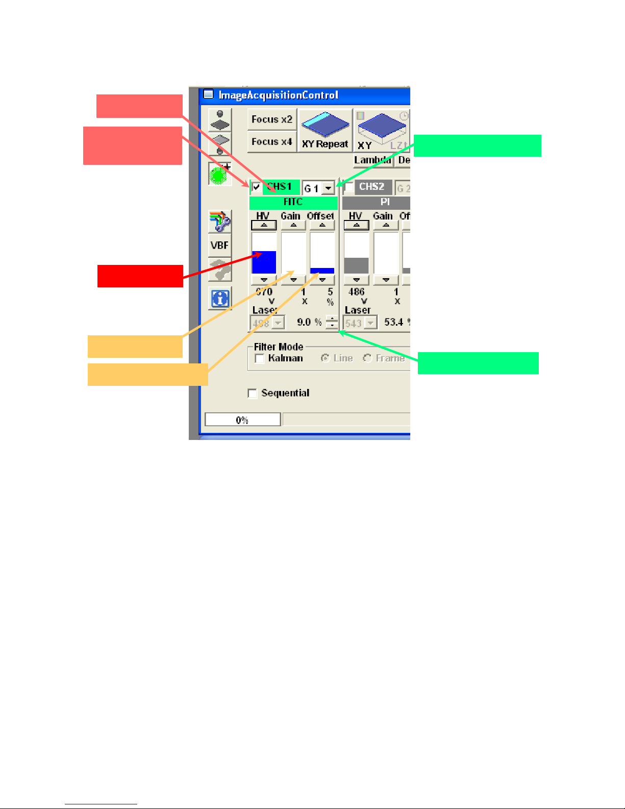
V.M. Bloedel Hearing Research Center, Core for Communication Research
5.6 Channel
Olympus Fluoview-1000 User’s Guide
Center on Human Development and Disability, Digital Microscopy Center
5.7 Active if
checked
5.1 PMT Voltage
5.2 Amplifier Gain
5.3 Offset (black level)
5.5 Channel group
5.4 Laser Settings
Figure 5. Channel Settings for the Photomultiplier Tube (PMT)
2.5 Laser Controls.
Each fluorophore selected in the Dye List will select an appropriate laser line and some default intensity
setting. The Line Setting values are given as a percentage of full rated output of the laser (mW) entering
the scanhead. You can change the power setting for each line or turn lines off to assess bleedthrough
(details of bleedthrough are in section 6).
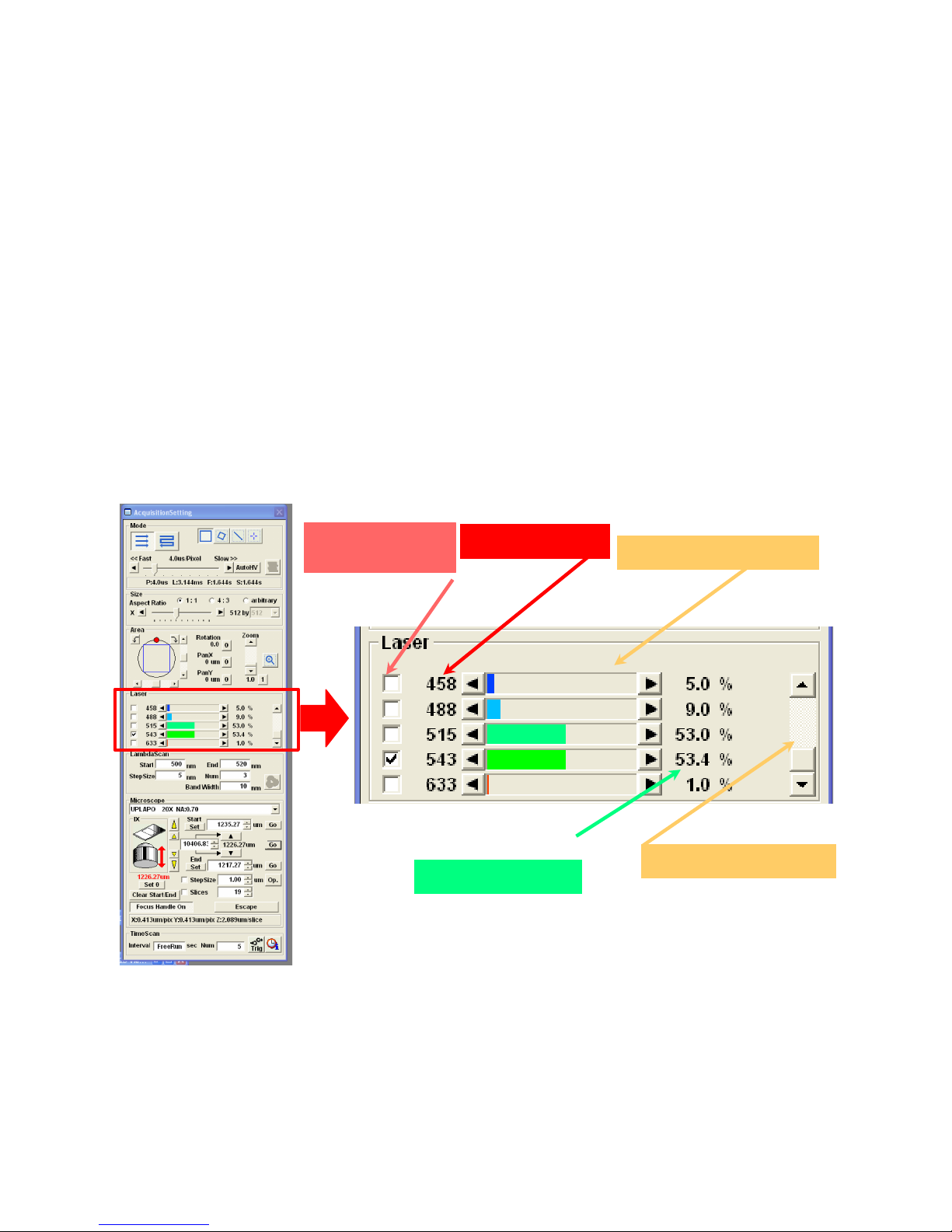
2.5.1 Line Selection.
Active lines are indicated by a check mark, Figure 7.1. Clicking in these boxes will toggle lines
between active and blocked. This control blanks the lines in the scanhead, it does not turn the laser itself
on or off.
2.5.2 Line availability, Figure 7.2.
Laser lines associated with each set of controls are listed in this column. This list is not affected by a
whether or not a laser has been powered up.
May 11, 2011 14
Olympus Fluoview-1000 User’s Guide
V.M. Bloedel Hearing Research Center, Core for Communication Research
Center on Human Development and Disability, Digital Microscopy Center
2.5.3 Laser Power Selector, Figure 7.3.
These controls regulate the percentage of laser power allowed to pass through the acoustico-optical
tunable filter (AOTF) located in the scanhead. Each individual laser has a unique output power. Thus, if
all laser lines are set at any given percentage, each will be providing a different amount of energy to the
sample.
2.5.4 Scroll List, Figure 7.4.
If there are more lines than can be displayed in the window, scroll through the list by clicking on the
black triangles or by dragging the slider.
2.5.5 Line Settings, Figure 7.5
As with other controls, the laser power may be adjusted by clicking anywhere in the control area,
scrolling the thumbwheel (1% increments) or by clicking on the black triangles (0.1% increments).
Using the thumbwheel to go below 1% will set the laser power to 0%. Use the triangles to increment
laser intensities to values between 0% and 1%.
7.1 Laser Line
Selection
7.2 Laser Line
7.5 Line Settings
7.3 Line Power Selector
7.4 Scroll List of Lines
Figure 7. Selecting laser lines and setting laser power
May 11, 2011 15
 Loading...