

Page 1
Users Manual
Fluoview
Scanning Laser Biological Microscope
Ver. 1.1
WARNING
A
Caution:
Before using your microscope, the items in this manual
Identified by the mark shown to the left should be read
carefully until completely understood to ensure safe
operation.
Thank you for purchasing an Olympus Fluoview Microscope.
Before using your microscope, read this manual thoroughly to
make sure you obtain full performance from all of the functions
provided by this system.
This manual is divided into the following five sections:
For Safe Usage
Introduction to Fluoview
Operation
Hardware
Troubleshooting Q & A
OIVMPUS'
August 1996
Page 2
raj
?3
n
IF=°
-About This Manual
This manual explains potential risks and provide important
safety information designed to ensure the safe use bf the
FLUOVIEW System. Thoroughly study this manual before
operating the system.
Page 3

1 Safety Precautions
2 Warning Labels
A
CONTENTS
1-1
2-1
2-1 Warning Labels Concerning Laser Safety 2-1
2-1-1 Warning Labels 2-1
2-1-2 Aperture Label 2-3
2-1-3 Protective Housing Label 2-5
3 Precautions for Use of the System 3J^
Page 4
1.
Safety Precautions
1 Safety Precautions
A
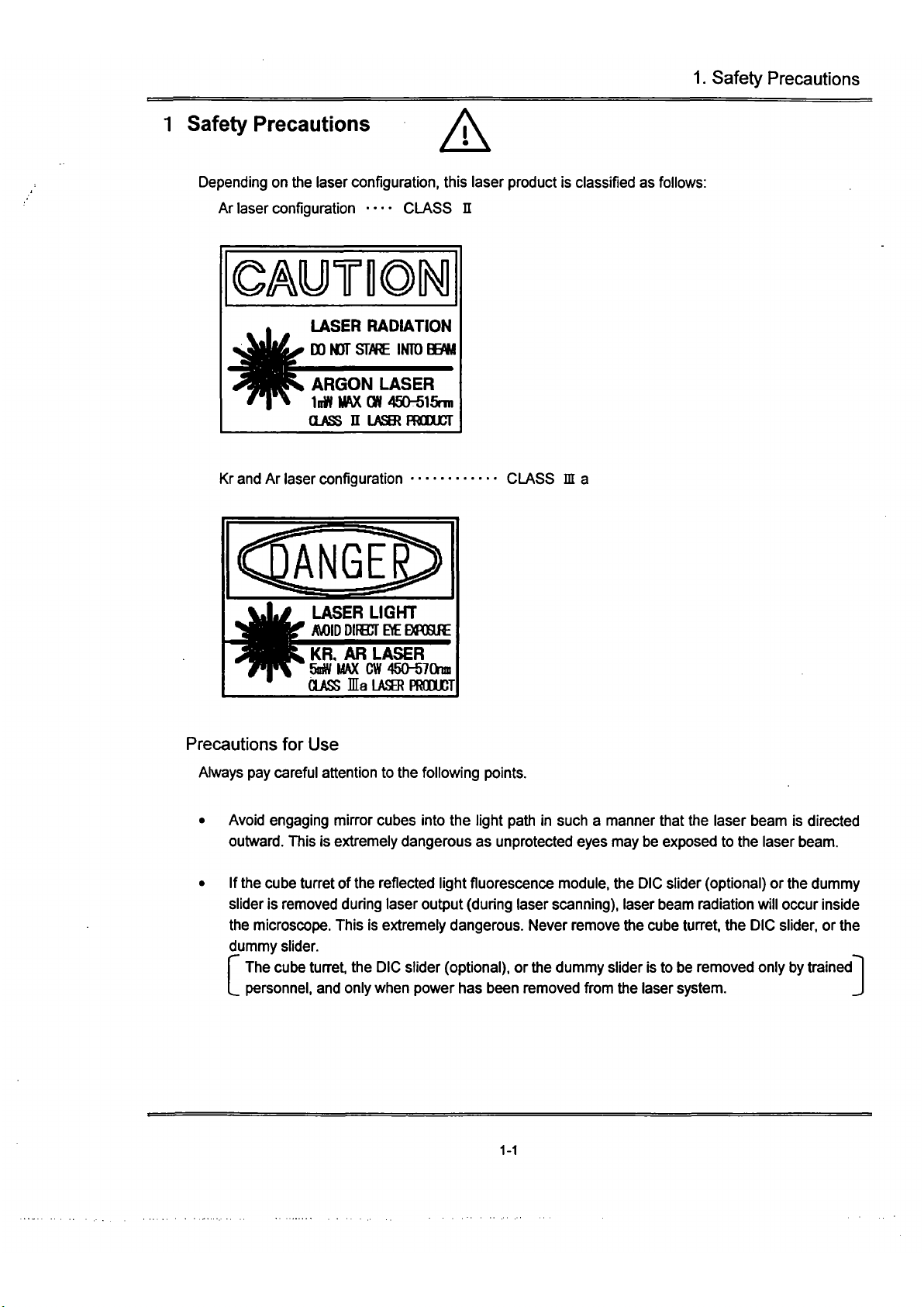
Depending on the laser configuration, this laser product is classified as follows:
Ar laser configuration — CLASS n
OAyilONl
LASER RADIATION
DO NOT
S[fPt
IN1D
Sm
ARGON LASER
InW Mf\X
CW
450-515nn
(LASS n LASKPRGDUCT
Kr and Ar laser configuration
CLASS in a
ANGE
LASER LIGHT
/M)IDD!fB]TBEB«RRE
KR. AR LASER
SniW
MAX CW
450-570na
CLASS la
LASER
PRdXJCT
Precautions for Use
Always pay careful attention to the following points.
Avoid engaging mirror cubes into the light path in such a manner that the laser t>eam is directed
outward.
This is extremely dangerous as unprotected eyes may be exposed to the laser beam.
If the cube turret of the reflected light fluorescence module, the DIC slider (optional) or the dummy
slider is removed during laser output (during laser scanning), laser beam radiation will occur inside
the microscope. This is extremely dangerous. Never remove the cube turret, the DIC slider, or the
dummy slider.
I The cube turret, the DIC slider (optional), or the dummy slider is to be removed only by trained
L personnel, and only when power has been removed from the laser system.
']
1-1
Page 5
1.
Safety Precautions
If the objective revolving nosepiece or the objective lens is removed during laser output (during
laser scanning), the laser beam will be emitted uncontrollably. This is extremely dangerous. Never
remove the objective revolving nosepiece or the objective lens.
TThe nosepiece or the objective lens is to be removed only by trained personnel, and only when
[_ power has been removed from the laser system.
]
If the transmitted light lamp housing or the lamp socket is removed during laser output (during
laser scanning), the laser beam light will be emitted uncontrollably. This is extremely dangerous.
Never remove the reflected light lamp housing or the lamp socket.
The transmitted light lamp housing or the lamp socket is to be removed only by trained
personnel,
and only when power has been removed from the laser system and from the
microscope.
• If the scan unit's (2) detection mode selector slider is detached during laser output (during laser
scanning), laser beam radiation will occur inside the microscope (beam reflected from the
specimen). This is very dangerous. Never remove the scan unit's detection mode selector slider.
The scan unit's (2) detection mode selector slider is to be detached only by trained personnel, |
_and only when power has been removed from the laser system. J
• Using tools to remove the protective housing, or otherwise dismantling/remodeling units, is
extremely dangerous as this may lead to uncontrollable laser beam radiation inside the unit Never
attempt to dismantle/remodel the system.
• Never excessively bend, strain, or step on the optical fibers. Damaged optical fibers may result in
laser beam leakage. This is extremely dangerous. Should the optical fibers be damaged,
immediately turn OFF the laser power supply unit and contact your Olympus representative.
• Hot air is emitted from the laser cooling fan exhaust outlet. Keep flammable materials and
materials adversely affected by heat at a safe distance of the outlet.
• The power consumption of both the power unit and the laser unit is very large. Ensure that each
unit obtains power from separate electrical systems.
• To prevent shock hazards, always ground the equipment.
• Always unplug the power cord before replacing fuses.
• Since the mixture (ether (70%) and alcohol (30%), etc.) used to clean the optical components of
the system is highly flammable, be careful to keep these chemicals away from open fire and
potential sources of electrical sparks, such as when the main switches are moved to
"I"
(ON) or
"O"
(OFF).
1-2
Page 6
1.
Safety Precautions
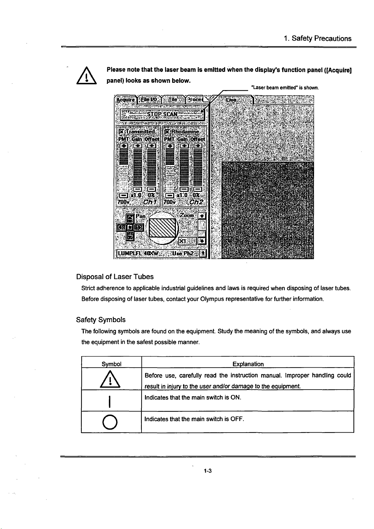
A
Please note that the laser beam is emitted when the display's function
pane!
([Acquire]
panel) looks as shown below.
"Laser beam emitted" is shown.
w}iFjmt^axv/),^^.\jiu»:p^
Disposal of Laser Tubes
Strict adherence to applicable industrial guidelines and laws is required when disposing of laser tubes.
Before disposing of laser
tubes,
contact your Olympus representative for further information.
Safety Symbols
The following symbols are found on the equipment Study the meaning of
the
symbols,
and always use
the equipment
in
the safest possible manner.
Symbol
A
O
Explanation
Before use, carefully read the instmction manual. Improper handling could
result in injury to the user and/or damage to the equipment
Indicates that the main switch is ON.
Indicates that the main switch is OFF.
1-3
Page 7

2.
Warning Labels
2 Warning Labels
2-1 Warning Labels Concerning Laser Safety
2-1-1 Warning Labels
(1)
Ar
laser configuration
©AUTIOff^
LASER RADIATION
DONdTSIWE INTDB^
ARGON LASER
Inn IMX
cn
45Ch515nn
CLASS n LASBIPRCOUCT
(2)
Kr
and
Ar
laser configuration
ANGE
LASER LIGKT
MIDDIIECrBEenHIE
Ka
AR
LASER
SaWMAX CW45O-570niD
CLASS
la
LASe)
PRODUCT
Attached position
BX50 configuration (Similar
in
case
of
BXWI configuration)
(Dor (2)
*^^MiiSr'
r
-
2-1
Page 8
2.
Warning Labels
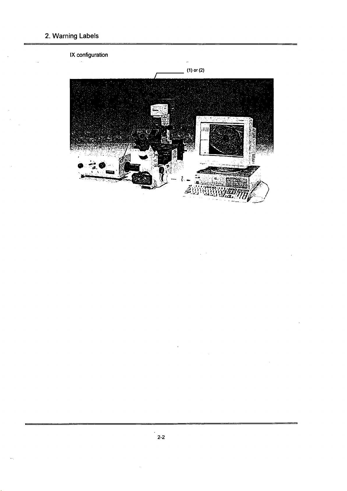
IX configuration
(Dor
(2)
2-2
Page 9
2.
Warning Labels
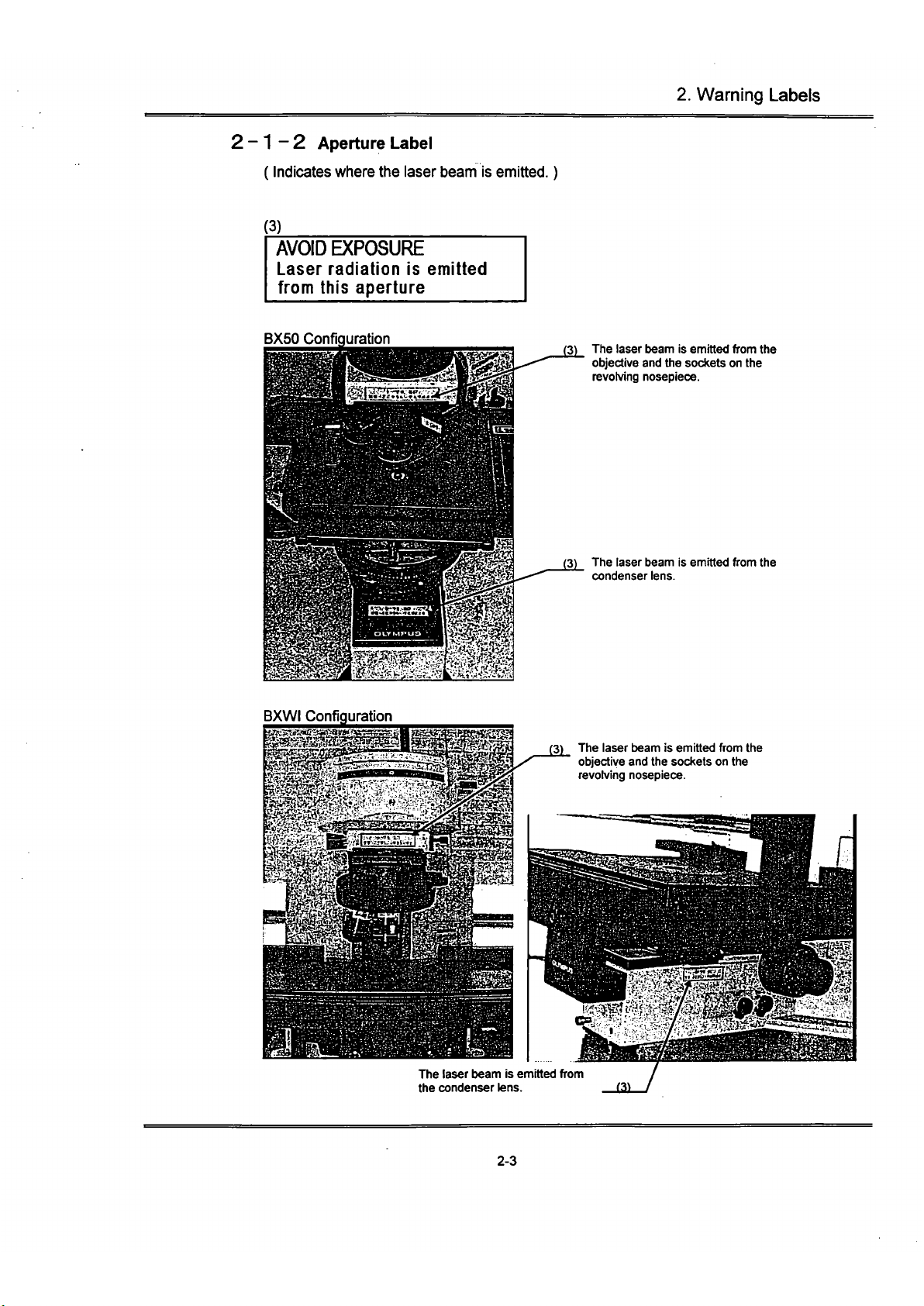
2-1-2 Aperture Label
(Indicates where the laser beam is emitted.)
(3)
AVOID EXPOSURE
Laser radiation is emitted
from this aperture
BX50 Configuration
(3) The laser beam is emitted from the
objective and the sockets on the
revolving nosepiece.
(3) The laser beam Is emitted from the
condenser lens.
BXWI Configuration
(3) The laser beam Is emitted from the
objective and the sockets on the
revolving nosepiece.
The laser beam is emitted from
the condenser lens. 13)
2-3
Page 10
2.
Warning Labels
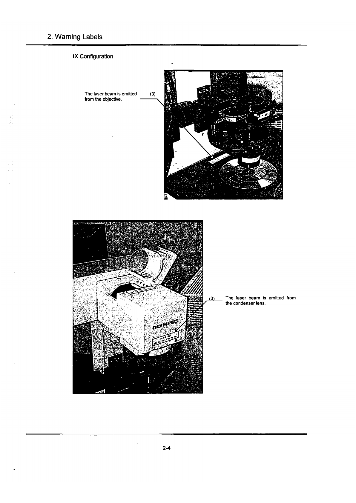
IX Configuration
The laser beam is emitted (3)
from the objective.
(3) The laser beam is emitted from
the condenser lens.
2-4
Page 11
2.
Warning Labels
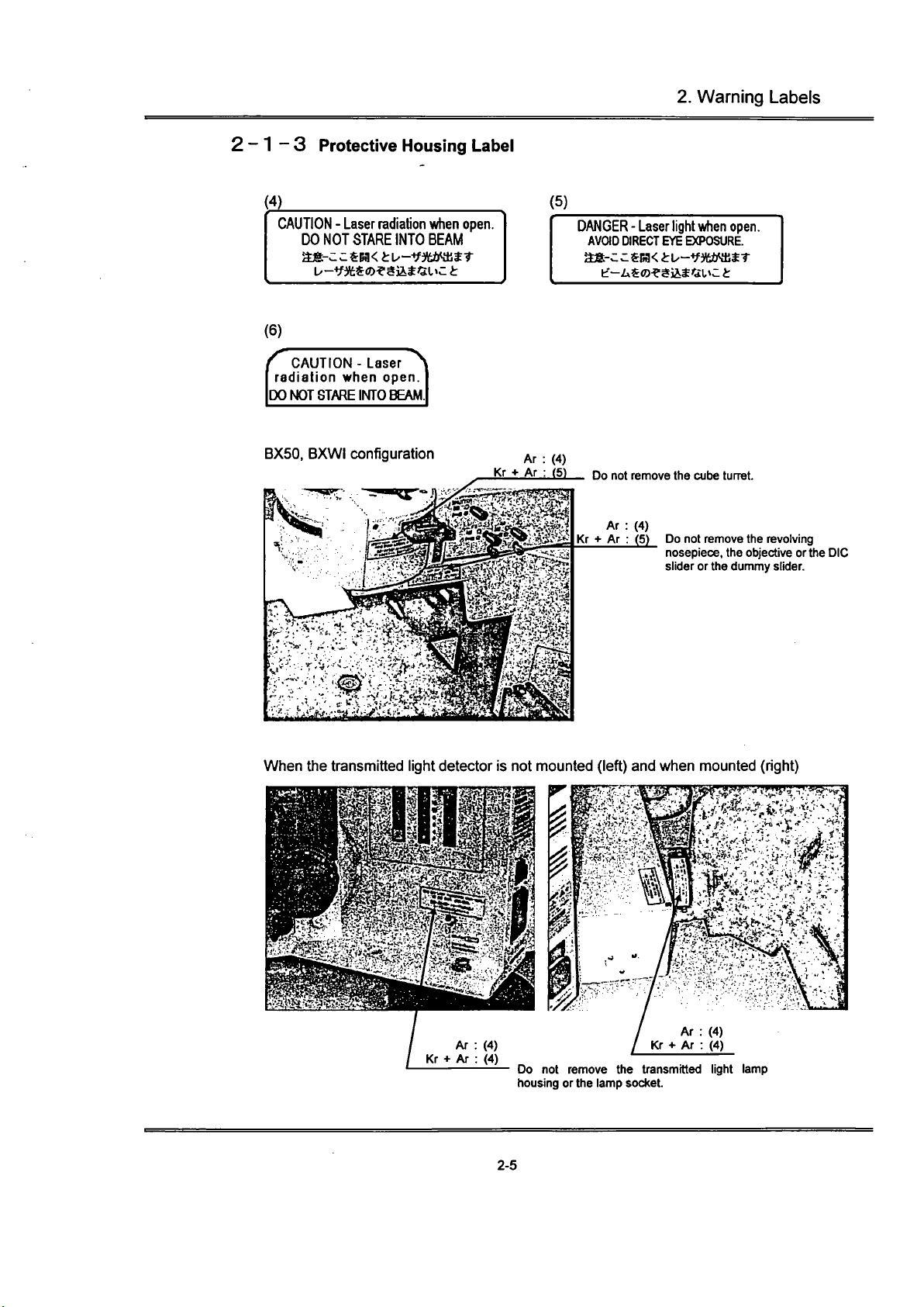
2-1-3 Protective Housing Label
(4)
CAUTION - Laser radiation when open.
DO NOT STARE INTO BEAM
t/-^f3tS®^ajit«L»c
t
(5)
DANGER - Laser light
when
open.
AVaO DIRECT
EYE
EXPOSURE.
CAUTION - Laser
^
radiation when open.
jDO NOT STARE INTO BEAM
BX50,
BXWI configuration
Ar
: (4)
Kr •»
Ar : (5)
Do
not
remove the cube turret.
Do
not
remove the revolving
nosepiece, the objective or the DIC
slider or the dummy slider.
When
the
transmitted light detector
is not
mounted (left) and when mounted (right)
(30
not
remove
the
transmitted light lamp
housing or the lamp socket.
2-5
Page 12
2.
Warning Labels
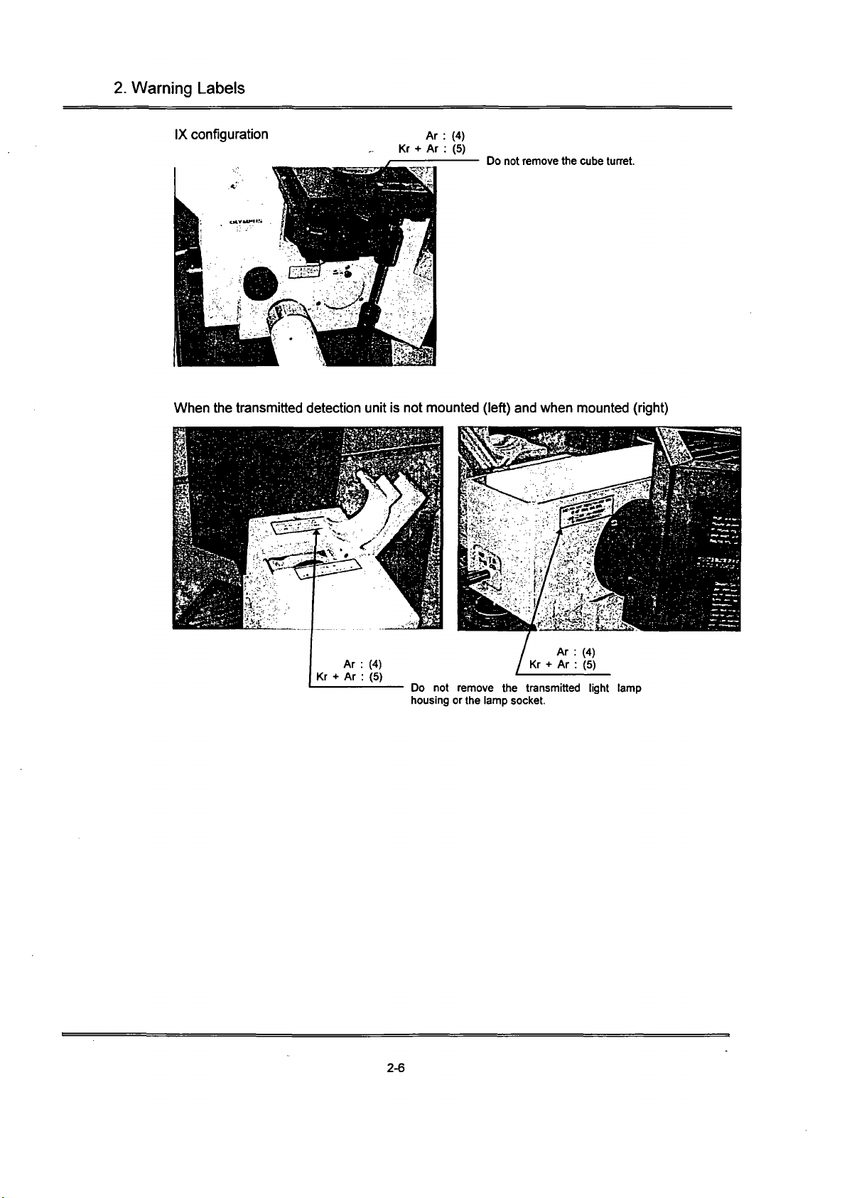
IX configuration
Ar : (4)
Kr + Ar : (5)
Do not remove the cube tuaet.
When the transmitted detection unit is not mounted (left) and when mounted (right)
Do not remove the transmitted light lamp
housing or the lamp socket.
2-6
Page 13
2.
Warning Labels
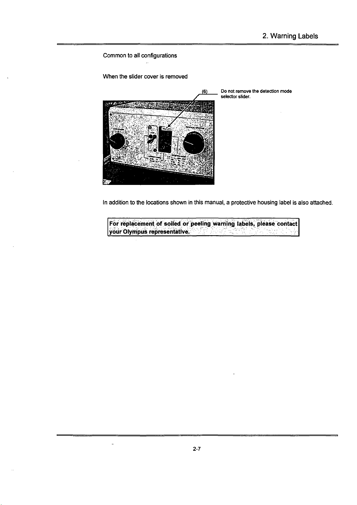
Common to all configurations
When the slider cover is removed
(6) Do not remove the detection mode
selector slider.
In addition to the locations shown in this manual, a protective housing label is also attached.
For replacement of spiled brp warriihg labblSi^ pibaise cohtact
your Olympus representative. r ^^^'..'
•.:'.'
:.'r ••• '••••:;:'
•. •
vr
2-7
Page 14
3. Precautions for Use of the System
3 Precautions for Use of the System
Installation
• The FLUOVIEW system will be assembled and setup by qualified technicians. Avoid moving the
system as this may adversely affect the adjustment of the optical system. In case it becomes
necessary to move the system, please consult your Olympus representative.
Olympus shall not be liable for improper adjustments, damages, or other problems occum'ng as a
result of the system being moved by the customer or other unauthorized personnel.
• Pulling the optical fiber in case of the KrAr laser configuration will change the laser output
Never modify by pulling the optical fiber.
• To prevent overheating, leave at least 30 cm of free space t>etween the exhaust opening of the
laser cooling fan and walls or other objects. Laser tube overheating will result in unstable laser
oscillation or the laser oscillation may stop. Excessively high temperature inside the unit may also
result in malfunction and/or damage.
• Openings for a cooling fan for ventilation are provided on the rear panel of the control unit
computer, and the magneto-optical disk unit. To prevent the risk of overiieating and other damage,
the openings should never be blocked. Leave at least 10 cm of free space between the openings
and walls or other objects.
Avoid installation in places exposed to direct sunlight high humidity, high temperatures, and dust
Operating environment: Ambient room temperature 10~35°C; relative humidity 30~80%.
• Avoid installation in places exposed to vibrations. Consult your Olympus representative if the
location is subjected to vibrations.
Handling
• The FLUOVIEW system is a precision instrument. Handle it with care and avoid subjecting it to
sudden or severe impact
• Never excessively bend, strain, or subject the laser fiber to crushing force as this will result in
reduced performance.
• The piezoelectric stage and the piezoelectric nosepiece (option) employ a piezoelectric element
which is fragile. Never subject to impact and ensure that undue force is never applied to these
units.
Precautions for Use
• When the built-in power supply for transmitted light is tumed on for a long time, accumulated heat
may cause metal to stretch and the focus to drift. To achieve highly precise image data, it is
recommended to turn OFF the main switch on the microscope frame.
3-1
Page 15
3. Precautions for Use of
the
System
• Standard objectives for biological use are employed for both the upright microscope system
configuration (BX) and the inverted microscope system configuration (IX). Accordingly, use cover
glass with a thickness of 0.17 mm or Petri dishes with a bottom thickness of 0.17 mm.
It is recommended to use special cover glass for LSM water immersion objectives.
• When using the FLUOVIEW system, it is recommended to dim the light in the room to reduce the
adverse effects of extraneous light.
• To ensure a stable laser beam output allow at least 10 minutes for warm-up after the laser power
supply is tumed ON.
• After tuming the reflected light power supply OFF, wait at least 10 minutes before tuming ON
again.
Tuming ON sooner will reduce the service life of the mercury burner.
About the Computer
and
Software
• Microsoft Windows are pre-installed on the computer for use with the FLUOVIEW system.
Microsoft Windows are pre-installed on the computer for use with the FLUOVIEW system.
The customer should make a back-up of the pre-installed program and store the back-up floppy
disks carefully. (Olympus offers no support for back-up, missing back-up, etc.)
For details on Microsoft Windows, refer to the User's Manual for Microsoft Windows.
• When the empty capacity of the hard disk becomes low, data processing will become very slow.
Periodically erase unnecessary data files from the hard disk. For details on erasing data files, refer
to the User's Manual for Microsoft Windows.
• When closing the software, always click the <Exit> button at the bottom of the [File I/O] panel. If
you display Windows' [Task List] dialog box and click the <End Task> button to close the software,
the file conditions, etc. of the last session will not be saved and subsequently not recalled next
time the software is started.
• When using the Z-motor, bring the specimen into focus by operating the coarse (fine) adjustment
knob on the microscope frame after clearing the check from the [Keep locked] check box on the [Z
Stage] panel of the [Acquire] panel (refer to Section 4-2-3-1 in the Operation Manual). Operating
the focus adjustment knobs on the microscope frame while the [Keep locked] check box remains
checked may result in damage to the Z-motor.
3-2
Page 16

Concerning This Section
This section provides an overview of the Fluoview System
and should be read before the system is used.
After reading and understanding this section, please read
the Operation section.
Page 17
Contents
CAUTIONS 2
REGISTERED TRADEMARKS 2
CARE AND MAINTENANCE 3
MOVING THE FLUOVIEW 3
SECTION 1 INTRODUCTION H
1-1 Fluoview Manual Configuration 1-1
1-1-1 Users Manual Configuration 1-1
1-2 Conventions Used in This Manual 1-2
SECTION 2 SYSTEM OVERVIEW 2J.
2-1 Principle of Operation 2-1
2-2 Fluoview Features 2-2
2-3 Optical Path Diagram 2-3
2-4 System Configuration 2-4
2-4-1 System Units and Their Roles 2-4
2-5 Software Function Configuration 2-7
2-5-1 Software Panel Configuration 2-7
2-5-2 Function Panel and Display Panel 2-8
2-5-3 Drag and Drop Function Execution Icon 2-9
2-6 System Setup 2-10
2-6-1 Power Consumption 2-10
2-6-2 Tuming on the Power Supply 2-11
2-7 System Operational Procedure Overview 2-14
2-7-1 Fluorescent Light Observation Procedure 2-15
2-7-2 Transmitted Light Observation Procedure 2-16
2-8 Identifying Images From Different Methods of Observation 2-17
Page 18
Cautions
(1) This software and manual may not be reproduced in part or in their entirety without the express written
permission of Olympus.
(2) The contents of this manual are subject to change without notice.
Registered Trademarks
Microsoft, Microsoft Windows and Excel for Windows are registered trademarks of Microsoft Corporation of
the U.S.
All other company names and product names are the trademarks or the registered trademarks of the
respective companies.
Page 19

Care and Maintenance
(1) When not in use, always use the accessory cover to protect your microscope from dust.
(2) This microscope is a precision instrument, so do not disassemble any of the components.
(3) Keep dirt, fingerprints off the lenses and filters. Remove any dirt by wiping lightly with soft gauze.
Stubborn dirt can be removed by wetting the gauze with a mixture of alcohol and ether (3:7 ratio), or
benzene.
,::Ethei^
is highly <x>mbusUble^^^ cautipri when turiiihg'
* \ the main switch oh arid off.
(4) Clean the various parts by wiping with a soft cloth moistened with diluted detergent. Do not use organic
solvents because these can cause deterioration of the paint and plastic parts.
Moving the Fluoview
Avoid moving this microscope since this can adversely affect adjustment of the optical system.
Please consult with your Olympus sales representative before moving this system.
Olympus is not responsible for any problems resulting from moving this system.
Page 20
Section 1 Introduction
Section 1 Introduction
1-1 Fluoview Manual Configuration
There are two Fluoview manuals; the Users Manual and the On-screen Manual (on-line help).
The Users Manual consists of five sections. The contents of these sections are described below.
1-1-1 Users Manual Configuration
• For Safe Usage
This section explains the requests, cautions and wamings related to usage of the
Fluoview System.
• Introduction to Fluoview
This section provides an overview of the Fluoview System.
• Operation
This section explains the method of
operation,
including the input of images and different
types of image processing.
• Hardware
This section provides detailed explanations of the Fluoview System hardware functions
and specifications.
• Troubleshooting 0 & A
This section explains the various countermeasures that can be taken in case a problem
should occur.
1-1
Page 21
Section 1 Introduction
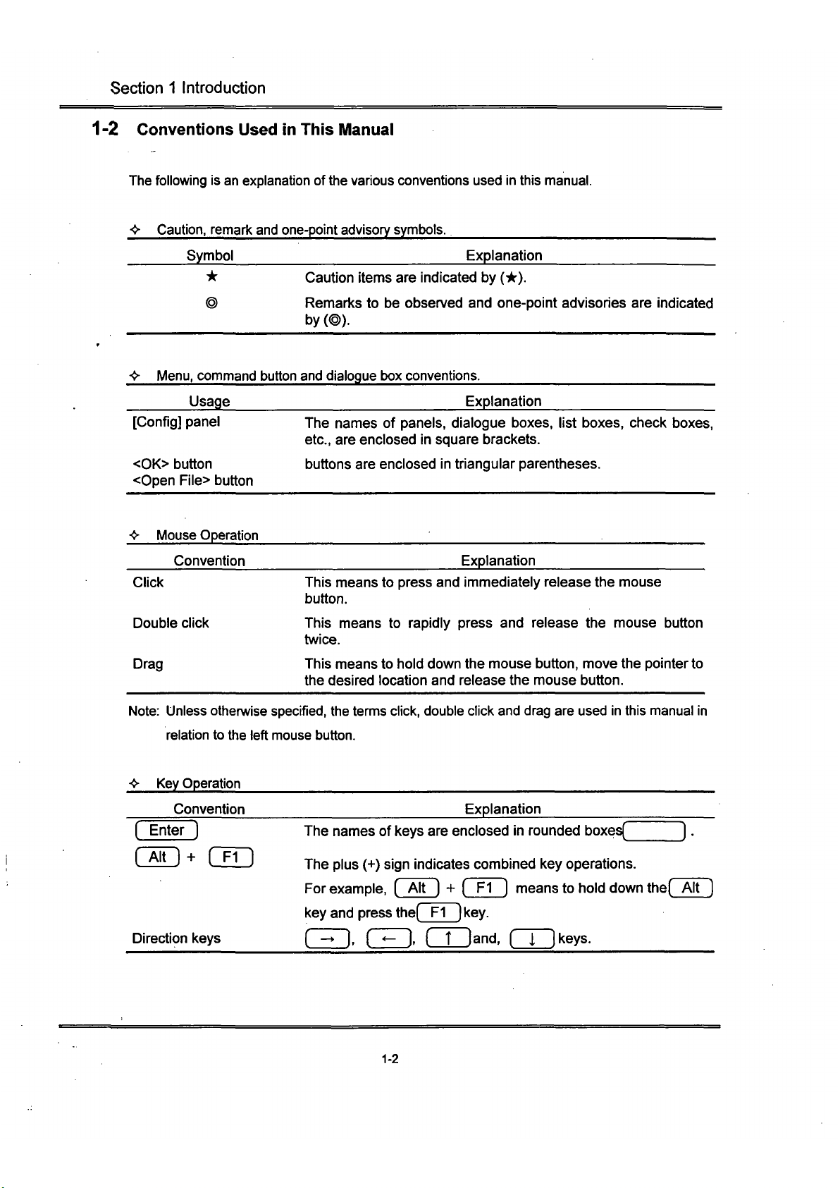
1-2 Conventions Used in This Manual
The following is an explanation of
the
various conventions used in this manual.
<•
<•
Caution,
remari< and
Symbol
*
one-point advisory symbols.
Explanation
Caution items are indicated by (*).
Remarks to be observed and one-point advisories are
by (@).
Menu,
command button and dialogue box conventions.
Usage
Explanation
indicated
[Config] panel
<0K> button
<Open File> button
The names of panels, dialogue boxes, list boxes, check boxes,
etc., are enclosed in square brackets.
buttons are enclosed in triangular parentheses.
•» Mouse Operation
Convention
Explanation
Click This means to press and immediately release the mouse
button.
Double click This means to rapidly press and release the mouse button
twice.
Drag This means to hold down the mouse button, move the pointer to
the desired location and release the mouse button.
Note:
Unless othen/vise
specified,
the temns click, double click and drag are used in this manual in
relation to the left mouse button.
••• Key Operation
Convention
Explanation
( Enter )
( Alt ) + fTT"
Direction keys
The names of keys are enclosed in rounded boxes(_
The plus (+) sign indicates combined key operations.
For
example,
( Alt ] + ( Fl ] means to hold down the( Alt
key and press the( Fl ] key.
( - ). CED. ( T
land,
nrikeys.
1-2
Page 22

^
Section 1 Introduction
> Terms Unique to This System
Convention Explanation
XY obsen/ation This means using XY scan to obsen/e.
(Other observation) (The same is for
XZ,
Xt, XVt and XYZt observation.)
1-3
Page 23
Section 2 System Overview
Section 2 System Overview
The Olympus Fluoview is a confocal scanning type laser fluorescent microscope that utilizes a common
focal point optical system to realize high resolution and high contrast as well as a spectacular
improvement in resolution in the optical axis.
This microscope provides researchers with the ability to perform automatic sectioning, three-dimensional
structuring and time fluctuation observation as well as various types of image processing and analysis.
2-1 Principle of Operation
Light detector
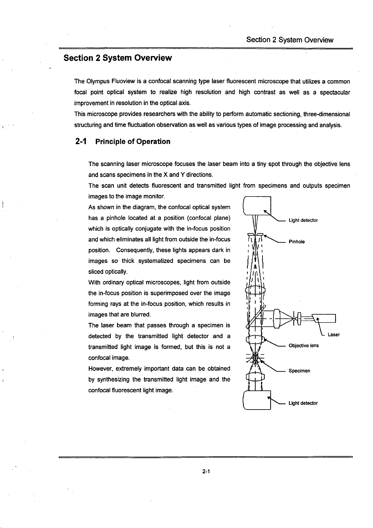
The scanning laser microscope focuses the laser beam into a tiny spot through the objective lens
and scans specimens in the X and Y directions.
The scan unit detects fluorescent and transmitted light from specimens and outputs specimen
images to the image monitor.
As shown in the diagram, the confocal optical system
has a pinhole located at a position (confocal plane)
which is optically conjugate with the in-focus position
and which eliminates all light from outside the in-focus
position.
Consequently, these lights appears dark in
images so thick systematized specimens can be
sliced optically.
With ordinary optical microscopes, light from outside
the in-focus position is superimposed over the image
fomiing rays at the in-focus position, which results in
images that are blurred.
The laser beam that passes through a specimen is
detected by the transmitted light detector and a
transmitted light image is formed, but this is not a
confocal image.
However, extremely important data can be obtained
by synthesizing the transmitted light image and the
confocal fluorescent light image.
Light detector
c)^
Laser
Objective lens
Specimen
2-1
Page 24
Section 2 System Overview
2-2 Fluoview Features
1.
The detector has a resolution of 12 bits, so images are extremely clear,
2.
1 A high-resolution 1024 x 768 pixel system is used. Non-interlaced output signals are used
for clear, flickeriess images.
3. Transmitted light is detected by a photomultiplier detector, so transmitted light images are sharp
and clear.
4.
An auto-gain function eliminates any need for bothersome sensitivity adjustment
5. Two image modes, 2-channel fluorescent images or fluorescent image + transmitted light
image,
can be selected with one touch.
6. The scan unit is corrected up to the infrared range to assure compatibility with a variety of
lasers. Use is also possible with both erect image and inverted image microscopes.
7. The confocal aperture is a 5-position turret, so the correct confocal aperture for each objective
lens can be selected with one touch.
2-2
Page 25
Section 2 System Overview
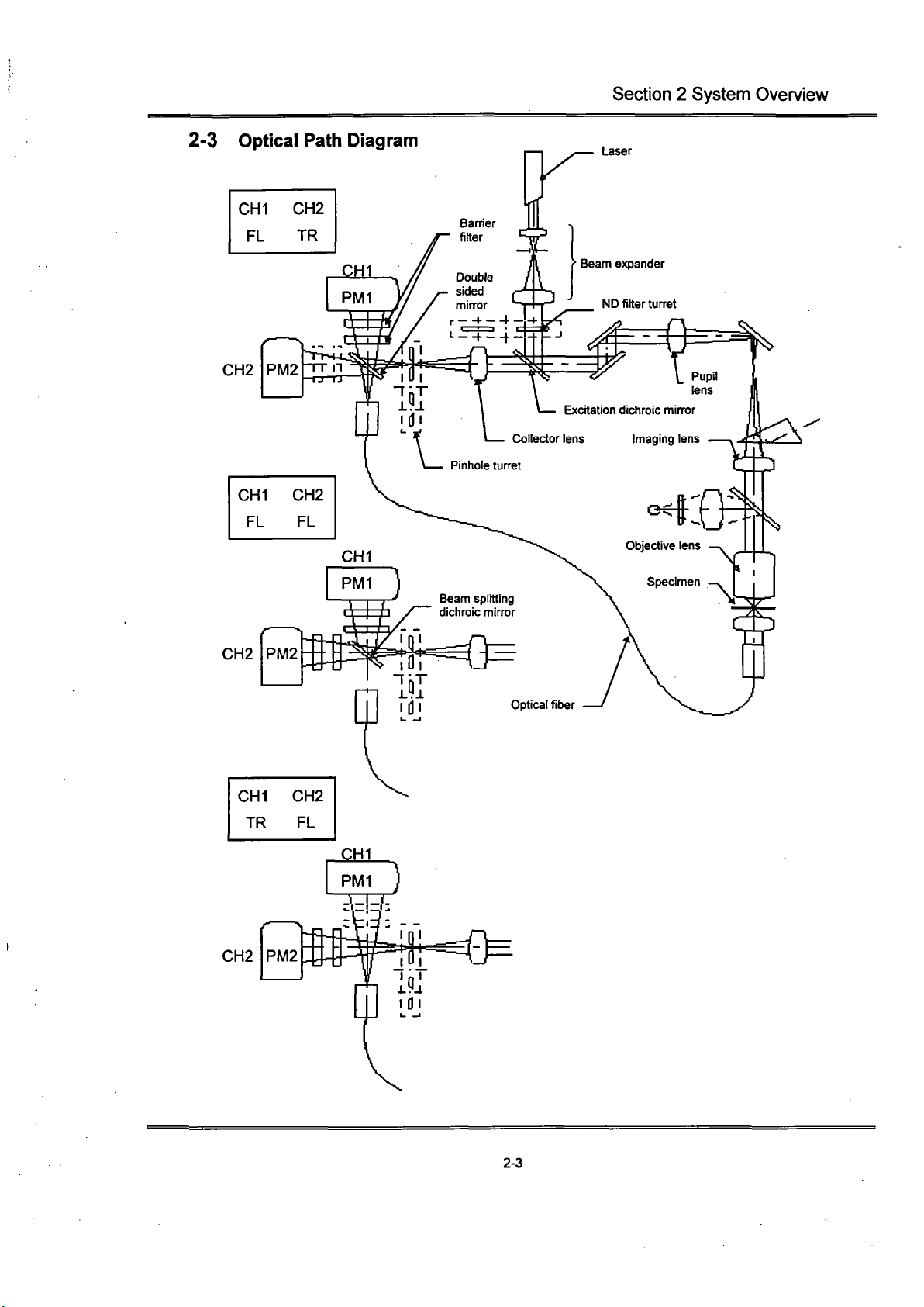
2-3 Optical Path Diagram
CHI CH2
FL TR
Laser
CH2
CH2
CHI CH2
TR FL
CH2
PM2
• —
2-3
Page 26

Section 2 System Overview
2-4 System Configuration
2-4-1 System Units and Their Roles
Scan unit
This unit scans the laser beam in the X and Y
directions and detects the light that retums.
Microscope
A BX50 erect image
microscope for fluorescent
observation.
type
light
Vertical stand
This stand supports
the scan unit to
prevent excessive
load being applied to
the microscope.
Transmitted light:
detector (option)
This unit is used to
obtain transmitted light
images.
Vibration-free
stand
Special rubber legs
eliminate vibration.
Microscope desk
Hard copy device
This device copies
images onto 35mm
or Polaroid
film.
Control Unit
Used to control the
scan unit and convert
detected signals into
images.
Electromagnetic disk
A large-capacity storage device
for storing images as files.
Image monitor
Used to display laser
scanned images,
operation panel, etc.
Power controller
A special table-top
controller for power supply
connections other than the
laser and Illumination bulb
power supplies.
Computer
Used for LSD control and
for storing Images as
files.
Computer desk
Laser power supply
The power supply for the
laser oscillator.
Illumination power supply
_ The power supply for the
mercury vapor illumination.
Photo
2-1
BX50 System
L^ser
unit
Consists of a laser oscillator and fiber
coupling (argon laser shown to the left).
2-4
Page 27

Section 2 System Overview
Microscope
A BXWI fixed stage erect image microscope
for fluorescent light observation.
VIbration-free stand
A special pneumatic type stand for
eliminating vibration.
^fis^.f •••"
Photo 2-2 BXWI System
Compressor
Supplies air to the vibration-free
stand.
2-5
Page 28

Section 2 System Overview
Microscope
AN 1X70 Inverted Image microscope
for
fluorescent light observation.
Vibration-free stand
A special pneumatic type stand
for eliminating vibration.
Photo 2-3
1X70
System
Pt^^ii^
^W
^r^F
pjfr-:
T*
fc^^
RK?
^m
mmM:n^
ij^feg
PH . ^-.«"-^'
'•"•••
i. .f^^S:
^^^ •^'•nn
'
'MF^'^Cz^m^D
"
iri'''**?**SPyt1rtit' • :K--<.'*S<
-':H^9BS^BHli ''^'''^''
t-*.—
'|~
"•'Vk'^'"^''*
%•
!)fj|;5l|;
^•^^^'.-'f-J.%'\
..'"' (,..ii^-—.^".
"^M'J^'.^'^
• •
••:V..<>rT"
""" •
iL
^
T^^W^HWll
• 1
^8H
Transmitted light detector (option)
This unit
Is
used
to
obtain transmitted light
images.
Compressor
Supplies air to the vibration-free stand.
2-6
Page 29

Section 2 System Overview
2-5 Software Function Configuration
This software uses panel type windows.
With conventional software, it is necessary to select a menu and then select the command to be
executed.
With panels, however, software functions can easily be executed by merely selecting
the panel index for the function to be executed, like a system notebook or file folder.
2-5-1 Software Panel Configuration
The panel indexes for all of the functions cannot be displayed at one time but must be
scrolled.
The panel list is shown below for use as reference when scrolling.
— Acquire
— Scan
— Z Stage
— Time Series
— Config
— File I/O
— Tile
— Process
— Math
— Filters
— Histogram
— Logical
— Analyze
— Single
'— Series
— Visualize
— Orientation
'— Other Options
2-7
Page 30

Section 2 System Overview
2-5-2 Function Panels and Display Panels
The Fluoview software utilizes two types of panels: the function panel and the display panel.
The functions panel includes the [Acquire], [File I/O], [Tile], [Process], [Analyze], and
[Visualize] panels.
The [Live] panel and [(File Name)] panel which are read in from a file are displayed in the
display panel.
Function panel ^ Display panel
•k With this software, a panel is simply called the '0000 panel' instead of the '0000 panel of
the function panel'.
For example, the [File I/O] panel of the function panel is simply called the [File I/O] panel.
2-8
Page 31

Section 2 System Overview
2-5-3 Drag and Drop Function Execution Icon
This software uses
the
drag
and
drop method
of
selecting image files
and
observation
methods (dye color name
or
transmitted light). With this intuitive method, selection requires
only picking
up
[Item
to
Select (image file
or
obsen/ation method)] with
the
mouse
and
dragging
it
to the setting location, where
it is
dropped.
*^ "•.•:.^-\ •::••••'.•,:'..
•
.Oi1:FITC!:."=.---:'':-; S-'-.--.
,;CH2:Rhodamin... ;,•.
;v.'
bVutV
-.-
-
tl
lniMit2'
1.
-1 ...,„
.:••• 1 dsar Bafcwl
6
::''\
^':;i^.TVl»,-;is;,j:-:<--y
:'0i
• •
f
TRITC
f
CY3
1
Texat
Re/
•
.
^^rn'.
Lucifei Yellow
_J,
Da
±1
.xyz-2.Tr
D
;XYCCE(iill2)
&![•
Scalaf Qpi/jrr
SciibrVakw
r''•'AJd
to'im»B»T
I
I' Sufahact hop Imagtf]
JMulliplyliMgBiiah
I
..|-. DivijB Image hy"
|
<r'.-.
MiitB Image Opt ~
Add 2 Ireaget.-
' |
Sufattact 2 Image!
MuBiiijf 2 Imaget
Experiments
in Men ory
CMMAGEV«YZ-2.TIF..'
Done
nmm^^md^
2-9
Page 32

Section 2 System Overview
2-6 System Setup
This system must be set up by a special technician. To maintain the perfonnance and for safety,
never disassemble or re-adjust this system.
2-6-1 Power Consumption
As shown below, some of the units consume considerable
power;
therefore, check the
capacity of the power outlet before connecting this system.
Microscope
Control unit
Electromagnetic
disk
IHard copy unit
Monitor
3A
Max.
3A
Max.
j 0,3A Max. IA Max,
Power controller
(up to 15A max, can be connected)
Personal computer
I.SAMax,
3A Max.
AC100V12.1AMax.
O
Fluorescent Illumination
power supply
(BH2-RFL-T3)
AC100V2.8AMax,
O
Argon laser power
supply
ACIOOVIOAMax.
O
Krypton/argon laser
power supply
200VAC, single-phase,
20Amax.
<
2-10
Page 33

Section 2 System Overview
2-6-2 Turning on the Power Supply
Tum on the power supply of each unit.
When only reading data, the laser power supply and illumination power supply are not
necessary and need not be tumed on.
To obtain a stable laser output, tum on the laser power supply and allow the system to warm
up for 10 min. or more before using.
Once the illumination power supply (mercury vapor lamp power supply) has been tumed off,
do not turn it on again for at least 10 min. to avoid shortening the service life of the mercury
vapor lamp.
• Tuming on the laser power supply
Argon laser:
(1) Turn on the power supply switch.
(2) Turn the key to the ON position.
Krypton/argon laser:
Please refer to the laser
instruction manual.
Please refer to the laser instruction
manual.
(1) Tum on the power supply switch.
(D
2-11
Page 34

Section 2 System Overview
• Tuming on the power controller power supply
(1) Tum on the main switch.
For details, refer to the Power Controller
SSI-9501 instruction manual.
(2) Tuming on the switches
If
all
of the switches are tumed on, the power
for the entire system can be tumed on and
off
with
the main switch as described in item
(1)-
The units are connected as shown below.
Computer
Monitor
Hard copy device
Electromagnetic disk
Microscope
2-12
Page 35

Section 2 System Overview
Tuming on the control unit power supply
(1) Turn on the power supply switch.
This unit is connected to the power controller, so the
power switch can be left turned on.
• Tuming on the electromagnetic disk power supply
(Please read the electromagnetic disk instruction manual.)
This unit is connected to the power controller, so the power switch can be left turned on.
• Tuming on the microscope power supply
(Please read the instruction manual of the microscope used.)
This unit is connected to the power controller, so the power switch can be left turned on.
2-13
Page 36

Section 2 System Overview
2-7 System Operational Procedure Overview
A flow chart is used here to explain the operational procedures so that operation of the entire system
can be more easily understood. For reference, the relevant manual sections (f j) and numbers
(( )) are indicated at the right side of the flow chart for each procedure. Please refer to 2-7-1
Fluorescent Light Observation Procedure and 2-7-2 Transmitted Light Observation Procedure.
2-14
Page 37

Section 2 System Overview
2-7-1 Fluorescent Light Observation Procedure
Start the system.
Prepare the system
(tum on the power supply).
Introduction to Fluoview (2-6)
Start the Fty<M/iew software.
Op9fati«>n(
2-1-1)
Look through the eiej^Hnti J^ns and focus on the speclmea
ISelect the li^pf^for
100%
for binocular
tube and
feiCttSidn
the specimen.
Har<iW»e(S-l-1)
•
Set to thft LSM light
path.
Set to the tSM light
path.
Hardware (3-1-2)
Set ^ scan unit.
[
Operate the det^t^tion mode setting
knob and^et the channel.
Har<IW8re(
3-1-4)
Insert the absorptK«t filter into the light
path!
Har<tware(
3-1-5)
Operate the pinhole turret and
se{.dd a pinhole.
Har(JWB(re(
3-1-3)
Operate th6 ND filter turret and
seled;*
ND filter
(100%.
50%, 20%, 6%).
.H^tJware
(3*1-6)
'••"• • --••• •)*-«••«•»'+ fy^yy^^ifr^i'^-^*
i
Replace with a high transmt^lifQn
rate ND filter (100%, 50%, 20%»6%).
Hardware -,
(3-1-6) . . ,
Read in an image.
Operation (3-1)
Set the ot)$en/ation
conditions.
\i
Scan once
<H:
repeatedly.
If the image is
not displayed,
•
adjust In
accordance
with the
;
The
imagels \
•
dsplayediofe^ ;
!software[Uv8] >
!
panel.
!
If^ima^jefs.
not dis{)layad.
( Adjust the PMt voltage, ^\
V lllll r [ f
tltspl«^ed.
iC
stop scanning.
I *M -It 4i * I
Shut down the system.
Shut
doWCi
the Ruoview software.
,
<;^>eration(
2-1-2)
•*:*•«
•«*(••
Shgl down the system.
(Tum off the power supply.)
2-15
Page 38

Section 2 System Overview
2-7-2 Transmitted Light Observation Procedure
start the system.
Prepare the system
(tum on the power supply).
Introduction to Fluoview (2-6)
start
the
fluoview softvyrare.
Operatton (2-1-1)
.
Look thraugti
the eyd(jto0^l0ns and
focus on
ttie specimen.
" Select
the
^; path for
100%
for ^
binocular
tube
and
focus
on the specimen.
:
H*dware
•Set to the LSM light
path.
Set to 1t)e LSM light
path.
HardWWe (3-2-3)
I f « Y.|»« I
Set Ihe scan unit.
Remove the microscope caps and
filters from the light
path.
[
Operate the dialection mode setting
knob and $et the channel.
Hardware (3-2-4)
Insert
the
absoi|7lJqc^ filter into the light
path.
Hardware (3-2-5)
Operate the ND filter turret and
sef0<:^
^ ND filter
(100%,
50%.
20%, 6%).
H^dw^re
(3-2-6)
^Replace with a high transmis^i;^ rate^
ND filter (100%, 50%, 20%,^5%).
Hardware '
(3-2-6)
Read in an image.
Operation (3-1)
• -w-^
*.j*
.•
<
Set the Ot)idervation
con<itlons.
Scan once dftepeatedly.
If the image is not
displayed,
adjust
In accordance with
the relevant
procedure.
%
m
The
image
is \
displayed l(t|he^
software [LjveJ »
panel.
*
if;dr)im«S«)9
Adjust the PMT voltage* J
If an iinei^e i$
tSsplayed,'
Stop scann^g.
Shut down the system.
Shut down the Fluoview softv\^are.
Operation (2-1-2)
Shtltdown the system.
(Turn off the power supply.)
2-16
Page 39

Section 2 System Overview
2-8 Identifying Images From Different Methods of Observation
Fluoview displays various image icons
which
can be used to identify the method of
obsen/ation
used
to read in images. (See the table to the
right)
When the [File I/O], [Tile], (Process],
[Analyze] and [Visualize] panels are selected,
the icon of the image of the selected
[Display] panel is displayed inside the box at
the top of the respective panel. Also, when
the icon area of
the
[Files] list box of
the
[File
I/O] panel or image file is dragged, the icon
of the image is used in various aspects.
This sen/es in the identification of the
method of observation.
Image icon
0
0
^
^
D
[h
^^
IS
BHI
Icon Meaning
XZ observation
XZ obsen/ation, 2-channel
mode
XT obsen/ation
XT observation, 2-channel
mode
XZT observation
XZT obsen/ation, 2-channel
mode
XY observation
XY observation, 2-channel
mode
XYt obsen/ation
XYt obsen/ation, 2-channel
mode
XYZ observation
XYZ obsen/ation, 2-channel
mode
XYZt observation
XYZt
observation,
2-channel
mode
Animated image
Binocular erect image/erect
image viewed through
colored glasses
2-17
Page 40

This instmction manual describes functions, specifications,
assembly (connections) and adjustment of the hardware.
Before reading this instmction manual, please thoroughly
review the preceding manual "INTRODUCTION TO
FLUOVIEW" for an outline of the system.
Page 41

LASER SAFETY PRECAUTION
Units indicated as "OPERATOR SERVICE" should be removed only by a person who has had laser safety
training,
and only after tuming off the laser unit. This should not be done by any untrained persons.
Removing any of the following units is considered to be OPERATOR SERVICE :
Cube turret
Objective revolving nosepiece
Objective lens
DIC slider or dummy slider
Transmitted light lamphousing and / or lamp socket
Detection mode selector slider ( Scan unit)
See
2-1,
2-7, 2-10.
Page 42

1 STANDARD CONFIGURATIONS
1 STANDARD CONFIGURATIONS
1-1 BX Upright Microscope System Configuration
bfesi&;SftM!3escnpbonMH?#g^
Scan Unit
Excitation Cube
Filter
Dual Wavelength Excitation
Cube
Banier Filter
Barrier Filter
Kr and Ar Laser Line Filter
Polarizing Filter for Upright
Microscope
Control Unit
Pupil Lens
Laser Tube
Extension Unit
Stand for BX
Rubber Feet Anti-Vibration
Table for BX
Ar Laser Unit 2
Ar Power Supply Unit 100
Laser Combiner
Z-Motor
Unit
Desk for Microscope Frame
Computer Desk
Microscope
Computer
Monitor 17"
Power Controller
SCSI Kit
Polaroid Recorder
FVX-SU
FVX-DM488
FVX-BA565IF
FVX-DM488/568
FVX-BA550RIF
FVX-BA585IF
FVX-LLF-KR
FVX-PO-U
FVX-CU
FVX-PL-IBX50
FVX-LT
FVX-EXTU
FVX-ST
FVX-UVT-BX
FVX-LU-AR2
FVX-PS-AR100
FVX-COM-KRAR
FVX-ZM
FVX-DK8070
FVX-DK6570
BX50-FLA-FVX
PC-AT-P95
M0NIT0R17
SSI-9501
SCSI-1510-JPN
FVX-POLA
ilBX5oy^ti§
1
1
1
S^^^ii
1
1-1
Page 43
CONTENTS
1 STANDARD CONFIGURATIONS t£t
1-1 BX Upright Microscope System Configuration 1-1
1-2 IX Inverted Microscope System Configuration 1-2
1-3 Optional Accessories 1-3
2 MAIN UNITS AND DESCRIPTION OF CONTROLS 2£L
2-1 Scan Unit 2-1
2-2 Microscope Frame 2-7
2-3 Transmitted Light Detector (Optional) 2-13
3 PREPARATIONS FOR OBSERVATION Z=l
3-1 Fluorescence Observation 3-1
3-1-1 Bringing the Specimen into Focus 3-1
3-1
-2
Selecting the LSM Light Path 3-3
3-1-3 Selecting the Pinhole 3-5
3-1-4 Selecting the Detection Mode 3-5
3-1-5 Engaging the Barrier Filter 3-5
3-1-6 Selecting the ND Filter 3-6
3-1-7 Selecting the Laser Line Filter (Kr and Ar Laser Combination) 3-6
3-2 Transmitted Observation 3-7
3-2-1 Selecting the Transmitted Light Detector Light Path (Visual Setting) 3-7
3-2-2 Bringing the Specimen into Focus 3-7
3-2-3 Selecting the LSM Light Path 3-8
3-2-4 Selecting the Detection Mode 3-10
3-2-5 Disengaging the Banier Filter 3-11
3-2-6 Selecting the ND Filter 3-11
4 SPECTRAL CHARACTERISTICS OF FILTERS 4=1
5 SPECIFICATIONS 5=1
Page 44

1 STANDARD CONFIGURATIONS
1-2 IX Inverted Microscope System Configuration
^nimsii^
Scan Unit
Excitation Cube
Filter
Dual Wavelength Excitation
Cube
Banier Filter
Banier Filter
Kr and Ar Laser Line Filter
Polarizing Filter for Inverted
Microscope
Control Unit
Pupil Lens
Air Anti-Vibration Table for IX
Compressor
Ar Laser Unit 2
Ar Power Supply Unit 100
Laser Combiner
Z-Motor
Unit
Computer Desk
Microscope
Computer
Monitor 17"
Power Controller
SCSI Kit
Polaroid Recorder
«Siiii^«»
FVX-SU
FVX-DM458
FVX-BA565IF
FVX-DM488/568
FVX-BA550RIF
FVX-BA585IF
FVX-LLF-KR
FVX-PO-U
FVX-CU
FVX-PL-IBX50
FVX-ST
FVX-UVT-BX
FVX-LU-AR2
FVX-PS-AR100
FVX-COM-KRAR
FVX-ZM
FVX-DK6570
IX70-FLA-FVX
PC-AT-P95
M0NIT0R17
SSI-9501
SCSI-1510-JPN
FVX-POLA
mmm^.
1
1
1
iHlli^
1
1-2
Page 45

1 STANDARD CONFIGURATIONS
1-3 Optional Accessories
Green HeNe Laser Unit
Dual Wavelength Excitation
~
Cube
Banier Filter
Transmitted Light Detector for
BX
Transmitted Light Detector for
IX
UCD Lens Unit
LWUCD Lens Unit
Piezoelectric Z-Stage
IX Frame (With Piezo)
Anti-Vibration Platform for IX
Barrier Filter
Banier Filter
Barrier Filter
Optional Banier Filter Slider
Optional Emission dichromatic
min-or Cube
FVX-LU-HEG
FVX-DM488/543
FVX-BA530RIF
FVX-TD-BX
FVX-TD-IX
LSM-THI-UCD
LSM-THI-WUCD
FVX-PZT-BX1
IX70-FVXPZ-F
FVX-UVT-TA
FVX-BA590
FVX-610IF
FVX-BA510-540
FVX-BA-OPT
FVX-SDM-OPT
Used In combination with the Ar laser. Suitable for
TRITC and PI obsen/ation. 543 nm excitation
wavelength. Can not be combined witii the Kr laser.
Dual wavelength excitation cube for Ar laser and
HeNe green laser.
Short-pass filter for blocking ttie 543 nm wavelength
beam emitted by the HeNe green laser.
Used for 488/543 nm dual wavelengUi excitation.
Transmitted Ught Detector for BX50/BXWI for
providing transmitted light to the scan unit via an
optical fiber connection.
Transmitted Light Detector for IX for providing
transmitted light to Uie scan unit via an optical fiber
connection.
Lens unit for use with the UCD condenser, mounted
on the FVX-TD-IX.
Lens unit for use with the LWUCD condenser,
mounted on the FVX-TD-IX.
When used with extemal sensor for fijil-cross
conti-ol.
this stage offers Z-movement with extremely
high position reproducibility. Minimum step of 0.1
^m;
stroke length 100 \im.
When used with extemal sensor for fijil-cross
control,
this IX frame offers Z-movement with
extremely high position reproducibility. Minimum
step of
0.1
^m; stroke lengtii 100 ^m.
Simple anti-vibration Platform for IX.
To minimize the fluorescence cross-over when
observing double-stained specimens, such as
FITC+TRITC, using ttie Ar laser (488 nm).
Band pass filter for use
writh
FITC.
Optional banier filter slider for customized filter
placement.
Compatible with a filter diameter of 13
.Q'3
mm and a
filter thickness of 2-3 mm.
Optional Emission DM cube for mounting a custom
dichromatic mirror to separate the fluorescence
emission for detection by the Channel 1 and
Channel 2 PMT. Compatible writti 18mm x 11 mm, 1
mm thickness dichroic minors.
1-3
Page 46

2 MAIN UNITS AND DESCRIPTION OF CONTROLS
2 MAIN UNITS AND DESCRIPTION OF CONTROLS
Also referto Section 2-4, SYSTEM LAYOUT in the "INTRODUCTION TO FLUOVIEW manual.
2-1 Scan Unit
(5) Filter slider
cover screws
USBt IIIEKITr
0
(4) ND filter tun^t
(6) Laser line filter turret (only for
Kr and Ar laser combination)
"OPERATOR SERVICE"
(2) Detection mode _ (D Pinhole tun^t
selector slider
o(E)«
:iECTION WOE
Ofl OC
H. IR
H. H.
TR R.
OLYMPUS
FLUOVIEW
(D
&
(3) Banier filter slider
(1) Pinhole turret
The pinhole sizes are as follows
1:60nm
The pinhole turret contains 5 pinholes. Allowing
selection of an optimum pinhole for all objectives.
Select the pinhole number displayed on the control
panel ([Acquire] panel).
If the acquired image is sufficiently bright and noise is
not aparent even when the photomultiplier HV is
raised,
an even better image may be obtained by
operating the pinhole turret and selecting a smaller
pinhole.
2:
lOOum
3: 150nm
4:
200nm
5: 300nm
}
Select either 1, 2 or 3 in accordance with the pinhole size indicated for a
given objective (see below).
Use to obtain a brighter image, Confocality is compromised.
2-1
Page 47

2 MAIN UNITS AND DESCRIPTION OF CONTROLS
In
general,
selecting a smaller pinhole than the pinhole size recommended for a given
objective
will
not increase the axial resolution. However, in some cases the lateral
resolution may
increase.
The effect differs with the refractive index of
the
specimen and
the dispersion of
the
light
The following table shows-the recommended pinhole number for a given objective.
o
\i^
Nl
•^i
, -
N.
N
Objective
PLAPO 40X
PLAPO 60XO
PLAPO 100XO
PLAPO 40XWLSM
PLAPO 60XWLSM
PLAPO 60XOLSM
UPLAPO 10X
UPLAPO 20X
UPLAPO 20XO
UPLAPO 40X
UPLAPO 40XO
UPLAPO 60X
UPLAPO 60XWPSF
UPLAPO 100XO
UPLFL10X
UPLFL20X
UPLFL40X
UPLFL60XO
UPLFL100XO
UMPLFL10XW
UMPLFL20XW
LUMPLFL40XW
LUMPLFL60XW
NA
0.95
1.40
1.40
0.90
1.00
1.10
0.40
0.70
0.80
0.85
1.00
0.90
1.20
1.35
0.30
0.50
0.75
1.25
1.30
0.30
0.50
0.80
0.90
Pinhole No.
2
2
3
2
3
3
1
1
1
2
2
3
2
3
1
2
3
2
3
1
2
2
3
2-2
Page 48

2 MAIN UNITS AND DESCRIPTION OF CONTROLS
(2) Detection mode selector slider
Slider for selecting either two fluorescence signals or one fluorescence signal + transmitted
light 3 settings. This slider is placed at the A-section shown in Fig, (I).
• Slide'r at the pushed-in position
Select this mode when observing a transmitted light and / or a fluorescence with
emission wavelength shorter than 570nm, such as FITC, GFP, DiO, etc.
As shown in Fig. (I) on the following page, a double-sided mirror is engaged into the light
path.
Consequently, fluorescence light is reflected to the CHI (PMI). When the transmitted
light detector (option) is
attached,
the transmitted light is reflected via the optical filter
connection to the CH2 (PM2).
• Slider at the middle position
Select this mode when observing a double-stained specimen, such as FITC+PI, etc.
As shown in Fig. (II) on the following page, a beam splitting dichroic mirror is engaged
into the light
path.
The characteristics of this dichroic minor make it reflect light with
wavelengths below 570 nm and pass the longer wavelengths. Consequently, the
fluorescence light can be split into light for the 1CH (PMI) and the 2CH (PM2). With the
slider at this position, the transmitted light from the optical fiber connection is blocked.
•
Slider at the pulled-out position
Select this mode when observing a transmitted light image and / or fluorescence
specimen with emission wavelengths longer than 570 nm, such as PI, TRITC, etc.
As shown in Fig. (Ill) on the following page, nothing is engaged into the light
path.
Consequently, fluorescence light is directed to the CH2 (PM2). When the transmitted
light detector (option) is attached, the transmitted light is directed via the optical fiber
connection to the
CH1
(PMI).
2-3
Page 49

2 MAIN UNITS AND DESCRIPTION OF CONTROLS
Laser
Slider at pushed-in position
CHI CH2
FL TR
Fig. (I)
Middle position
Fig.(n)
Slider at pulled-out position
Fig. (IE)
2-4
Page 50

2 MAIN UNITS AND DESCRIPTION OF CONTROLS
1
(3) Bamer filter slider
Up to two filters can be placed for both CHI and CH2. At the pushed-in position, the filter is
engaged into the light
path.
At the pulled-out position, it is disengaged.
* If erroneously placed at the middle position, no image will appear. Always stop at the
correct position.
(4) ND filter turret
There are five positions.
Transmission ratio: 0, 6, 20, 50, and 100%.
(5) Filter slider cover screws
Operated when the bamer filter slider or the detection mode selector slider is replaced.
When this screw is loosened, the covers can be pulled off. Then replace the sliders, retum the
cover to its original position, and tighten the screw again.
r Detection mode selector slider should be removed only, by a person who has had laser
L safety training, and only after tuming off the laser unit
(6) KrAr laser line filter tun-et
(Only attachable with the Kr and Ar laser combination)
Unit
writh
built-in 5-filter turret for selection in accordance with the 488 nm and 568 nm
excitation wavelength of the Kr
and
Ar laser.
(1)488:
The specimen is excited at 488 nm. Used for observation of single-stained
specimens, such as FITC.
(2) 568: The specimen is excited at 568 nm. Used for observation of single-stained
specimens, such as TRITC, PI.
(3) 568: The specimen is excited at 488 nm and 568 nm. However, the 488 nm output
488
°"'y'®
attenuated to 6% of the normal excitation light. Used for preventing the Pl
AT6 from eclipsing the FITC when observing double-stained specimens such as
FITC+PI.
(4) 568: The specimen is excited at 488 nm and 568 nm. However, the 488 nm output
488 only is attenuated to 25% of the normal excitation light Used for preventing the PI
AT25 from eclipsing the FITC when observing double-stained specimens such as
FITC+PI.
(5) 568: The specimen is excited at 488 nm and 568 nm. Used for observation of double-
+
^og Stained specimens, such as FITC+PI.
2-5
Page 51

2 MAIN UNITS AND DESCRIPTION OF CONTROLS
• FITC emission tails longer than 570 nm. Accordingly, FITC fluorescence may be
detected on the CH2 where it overlaps the Pl fluorescence. (See the figure below.) The
problem may be remedied by cutting the FITC by adjusting the OFFSET on the
operation panel ([Acquire] panel). If not, It will be necessary to balance the excitation
light by reducing the intensity of the 488 nm excitation light used for exciting the FfFC.
When observing a double-labeled specimen, such as FITC+PI, attempt balancing the
intensities ofthe emissions by engaging the (3), (4), (5) filters in the described order.
CH,
A
°°N
AT25 A A \
(FITC overlapping the j \ 1 I 1
CH2 can be reduced by / Vl 1 \
attenuating the excitation 1 \ \
Y
\\
CH2
/~
/
^ /
/\ /
PI
1
400 500 600
wavelength / nm
700
2-6
Page 52

2 MAIN UNITS AND DESCRIPTION OF CONTROLS
2-2 Microscope Frame
The illustration below shows the main controls of the microscope frame. The stage, revolving
nosepiece, etc., may differ from those illustrated.
For details on operation of the microscope frame, refer to the instruction manual for tiie
microscope frame.
BX50 Confiouration
(1) Light path selector
"OPERATOR SERVICE"
(2) Cube turret
"OPERATOR SERVICE"
nosepiece
"OPERATOR SERVICE"
objective lens
(6) Universal
(5) Filters
LBD
ND6
ND25
(3) Analyzer
U-AN
(optional)
"OPERATOR SERVICE"
(4) DIC prism
U-DICT(dummy slider)
(optional)
"OPERATOR SERVICE"
• transmitted light
lamphousing
• lamp socket
2-7
Page 53

2 MAIN UNITS AND DESCRIPTION OF CONTROLS
(1) Light path selector
• When the knob is pushed-in, visual observation is possible.
• When the knob is pulled-out laser microscopy is possible.
(2) Cube turret
• Engage the designated cube for visual fluorescence observation.
• When used as a laser microscope and for visual transrnitted light observation, operate the
turret to place the index at the [ { Q )] position.
(Set the cube turret so tiiat no cube is engaged.)
(3) Analyzer U-AN
(Optional)
• Engage the analyzer into the light path for visual transmitted Nomarski obsen/ation and
transmitted polarized light observation. The analyzer is engaged at the pushed-in position.
• Always remove the analyzer from the light path when used as a laser microscope. The
analyzer is disengaged at the pulled-out position. If the analyzer is engaged, a good image
cannot be achieved.
(4) DIC prism
U-DICT
(Optional)
• Engaged into the light path for laser Nomarski observation and visual transmitted
Nomarski observation.
An improved image is achieved if the
U-DICT
is removed from the light path in case of
laser fluorescence observation. For fluorescence observation alone, disengage the UDICT from the light
path.
[Leaving the
U-DICT
engaged during laser fluorescence observation will
degrade the image quality somewhat]
(1) Filter
• Always disengage filters from the light path for laser transmitted observation. A good
image will not be obtainable if a fllter is left engaged.
2-8
Page 54

2 MAIN UNITS AND DESCRIPTION OF CONTROLS
(2) Universal condenser
For Nomarski observation, engage the Nomarski prism (optional) suitable for the objective in
use.
(Similar for both visual and laser Nomarski observation.)
Note that tiie polarizer should also be engaged in the case of laser Nomarski obsen/ation.
(Note that the analyzer U-AN should be removed from Uie light path in tiie case of laser
Nomarski observation.)
[Note that laserphase contrast observation js hot poisfsil)le due to construction
'
"i''
',
limKatioris^"
.-!.••'^^'.'•;.?"''.,•.••'!•;,
\, '''•'"••'••'.';•
;j;i..''v--^''':'v^^;''v.-J'-''".'
"•"
2-9
Page 55

2 MAIN UNITS AND DESCRIPTION OF CONTROLS
IX Confiquration
(6) Filter
"OPERATOR SERVICE"
objective lens
(1) Light path selector
"OPERATOR SERVICE"
(2) Cube tunet
(7) Magnification selector knob
(3)
Analyzer
IX-AN
"OPERATOR SERVICE"
• transmitted light
lamphousing
• lamp socket
"OPERATOR SERVICE"
(4) DIC prism
U-DICT(dummy
slider)
(optional)
2-10
Page 56

2 MAIN UNITS AND DESCRIPTION OF CONTROLS
(1) Light path selector
• When tiie knob is set at the ^[ position, visual observation is possible.
• Set the knob at the ( SP ] position for laser microscope use.
(2) Cube turret
• Engage the designated cube for visual fluorescence observation.
• When used as a laser microscope and for visual transmitted light observation, operate tiie
turret to place the index at the [ [ O )] position.
(Set the cube tun'et so that no cube is engaged.)
(3) Analyzer IX-AN
(Optional)
• Engage the analyzer into the light path for visual transmitted Nomarski observation and
transmitted polarized light observation. The analyzer is engaged at the pushed-in position.
• Always remove the analyzer from the light path when used as a laser microscope. The
analyzer is disengaged at the pulled-out position. If the analyzer is engaged, a good image
cannot be achieved.
(4) DIC prism
U-DICT
(Optional)
• Engaged into the light path for laser Nomarski observation and visual transmitted
Nomarski observation.
• A better image is achieved if the
U-DICT
is removed from the light path in case of laser
fluorescence observation. For fluorescence observation alone, disengage the
U-DICT
from the light
path.
[Leaving the
U-DICT
engaged during laser fluorescence observation will
degrade the image quality somewhat.]
(1) Filter
• Always disengage filters from the light path for laser transmitted observation. A good
image will not be obtainable if a filter is left engaged.
2-11
Page 57

2 MAIN UNITS AND DESCRIPTION OF CONTROLS
(2) Condenser
For Nomarski obsen/ation, engage the Nomarski prism (optional) conesponding to the
objective in use. (This applies to both visual and laser Nomarski obsen/ation.)
Note that the polarizer should also be engaged for Nomarski obsen/ation. (Note that the
analyzer IX-AN should be disengaged for laser Nomarski observation.)
(3) Magnification selector knob
For LSM use, always select IX (knob pushed-in).
The 1.5X setting cannot be used.
[Note that laser phase coritrast obseivatloh is'.nbt possible due to cohstructibn
•^irhitations.]'-.-••.''-•;;:''•'••':•;•:'' • •:
.:";;""';\'\-'"-^-''•:••"*>•'>;
•.•• '•'•'• '"'• '',_ •'••'.:
2-12
Page 58

2 MAIN UNITS AND DESCRIPTION OF CONTROLS
2-3 Transmitted Light Detector (Optional)
FVX-TD-BX (for BX50, BXWI)
(1) Light paUi selector
• When the knob is pushed-in,
laser transmitted light
observation is possible.
• When the knob is pulled-out
visual transmitted light
observation is possible.
(D Light path selector
FVX-TD-IX (for IX)
• When the knob is pushed-in,
laser transmitted light
observation is possible.
• When the knob is pulled-out,
visual transmitted light
observation is possible.
(1) Light path selector
2-13
Page 59

3 PREPARATIONS FOR OBSERVATION
3 PREPARATIONS FOR OBSERVATION
This section explains the order of procedures for specimen obsen/ation.
3-1 Fluorescence Observation
3-1-1 Bringing the Specimen into Focus
3-1-1-1
BX50, BXWI Configuration
1.
Push in the light path selector knob (1) on tiie
binocular observation tube to select Uie 100% at
binocular eyepieces setting.
2.
Operate the cube turret to engage the cube
corresponding to the specimen fluorochrome.
3. While looking through tiie eyepieces, bring the
specimen into focus. Make sure to adjust the
eyepiece diopter correctly. (Refer to tiie BX
instmction manual.)
stage clips
* When using the Z-motor, clear the check from
the [Engage motor] check box (see Section 42-2-1 of the OPERATION MANUAL) on the [Z
Stage] panel on the [Acquire] panel. Then
operate the microscope frame's focusing
adjustment knob (fine) to bring the specimen
into focus. Damage to the Z-motor may occur
if the microscope frame's focusing adjustment
knob is operated while the [Engage motor]
check box Is checked.
* The specimen may float during oil immersion
observation.
While refening to tiie figure on the left, attach ttie
stage clips provided with the microscope frame.
3-1
Page 60

3 PREPARATIONS FOR OBSERVATION
3-1-1-2
IX Configuration
1.
Turn the light paUi selector dial (1) on ttie right
side of Uie microscope to the ^ position. While
looking through the eyepieces, bring the
specimen into focus.
Make sure to adjust the diopter adjustment ring
of Uie eyepiece. (Refer to the 1X50/70 instiuction
manual.)
2.
Operate the cube tun-et to engage the cube
corresponding to the specimen fluorochrome.
3. While looking through the eyepieces, bring the
specimen into focus. Make sure to adjust Uie
eyepiece diopter correctiy. (Refer to the IX
instmction manual.)
* When using the Z-motor, clear the check from
the [Engage motor] check box (see Section 42-2-1 ofthe OPERATION MANUAL) on the \Z
Stage] panel on the [Acquire] panel. Then
operate the microscope frame's focusing
adjustment knob (fine) to bring the specimen
into focus. Damage to the Z-motor may occur
if the microscope frame's focusing adjustment
knob is operated while the [Engage motor]
check box is checked.
* The specimen may float during oil immersion
observation.
While refemng to the figure on ttie left, attach Uie
stage clips provided witii the microscope frame.
3-2
Page 61

3 PREPARATIONS FOR OBSERVATION
3-1-2 Selecting the LSM Light Path
3-1-2-1 BX50, BXWI Configuration
1.
Pull out the light path selector (1) on the trinocular obsen/ation tube
to
the stop position.
2.
Operate the cube turret (2) on the vertical illuminator to align
the
index with
the [( Q ) ]
position.
3.
If
the analyzer U-AN
(3) is
mounted, disengage
it
by pulling
it
out to the pulled-out
clickstop. (Leaving
the
U-DICT
engaged during laser fluorescence observation will
degrade the image quality somewhat)
(D Light path selector
"OPERATOR SERVICE"
(2) Cube tun-et
"OPERATOR SERVICE"
nosepiece
"OPERATOR SERVICE"
objective lens
(6) Universal condenser
(5) Filters
LBD
ND6
ND25
(3) Analyzer
U-AN
(Optional)
"OPERATOR SERVICE"
(4) DIC prism
U-DICT(dummy slider)
(optional)
"OPERATOR SERVICE"
• transmitted light
lamphousing
• lamp socket
3-3
Page 62

3 PREPARATIONS FOR OBSERVATION
3-1-2-2
IX Configuration
1.
2.
3.
4.
Tum the light path selector (1) to the [[ SP J ] position.
Set the magnification selector knob (7) to lx.
Rotate the cube turret to select [ ( Q ]].
If the analyzer IX-AN (3) is mounted, disengage it by pulling it out to the far clickstop.
(Leaving the
U-DICT
engaged during laser fluorescence observation will degrade tiie
image quality somewhat.)
(6) Filter
OPERATOR SERVICE"
transmitted light
lamphousing
lamp socket
(5) Condenser
"OPERATOR SERVICE"
objective lens
"OPERATOR SERVICE"
(4) DIC prism
U-DICT(dummy slider)
(optional)
(1) Light path selector
"OPERATOR SERVICE"
(2) Cube tun-et
(7) Magnification selector knob
(3) Analyzer
IX-AN
(optional)
3-4
Page 63

3 PREPARATIONS FOR OBSERVATION
3-1-3 Selecting the Pinhole
Operate the pinhole tun-et (1) to select ttie pinhole corresponding to tiie pinhole number
indicated for
each
objective on tiie control panel.
(Refer
to
Section
2-1,
Scan Unit)
3-1-4 Selecting the Detection Mode
Set ttie detection mode selector slider to the designated position in accordance
with
Uie
fluochrome ofthe specimen to be
observed.
If
in
doubt about
Uie
setting,
refer to Section 41-2, Adjusting the Scan Unit, in the Operation Manual and follow the prompts of the
[Microscope Configuration] window.
Example for reference
Fluochrome
FITC
Lucifer Yellow etc.
FITC + TRITC
FITC + PI etc.
PI
TRITC
Detection Channel
CHI
CH1/CH2
CH2
Detection Mode Selector Slider
Position
Pushed in
Middle position
* Pulled out
(Referto Section
2-1,
Scan Unit)
* In case of single-stained specimens, a brighter
image can be observed if ttie slider is set at the
pushed-in or out positions. Avoid the niiddle
position.
3-1-5 Engaging the Barrier Filter
Depending on the
fluochrome
of
the
specimen to
be
observed,
engage barrier
Alters
as
required.
The banier
filter
slider is engaged into the light
path
at ttie pushed-in position, and
disengaged at
Uie
pulled-out position.
* No image will appear if the slider is stopped between the positions. Always set at
correct position.
If in doubt about the
setting,
refer to Section
4-1-2,
Adjusting the Scan Unit, in the
Operation Manual and follow the prompts of the [Microscope Configuration]
window.
Example for reference
Fluorochrome
FITC
FITC + PI
TRITC
CHI
BA510IF
BA510IF
-
—
(BA500-540)
—
CH2
—
BA565IF
BA565IF
—
(BA590)
—
3-5
Page 64

3 PREPARATIONS FOR OBSERVATION
(5) FIKer slider cover
screws
(2) [}etection mode
selector slider
UBBt IMTEI6ITY
0
(4) ND filter turret
(7) Laser line filter turret
(only
for
Kr and
Ar
laser
combination)
(1) Pinhole turret
~B|
9(S)9
OLYMPUS
FLUOVIEW
0
Jt
(3) Barrier filter slider
3-1-6 Selecting
the
ND Filter
Operate tiie
ND
filter
turret (4) to select the appropriate ND
filter.
Select the ND
filter
in
accordance with the specimen brightness and level
of
photobleaching.
The
ND20%
filter
may be appropriate to start
with.
3-1-7 Selecting
the
Laser Line Filter
(Kr
and
Ar
Laser Combination)
Operate the laser
filter
turret (7) to select the laser line
filter.
Examples for reference
Fluochrome
FITC
Lucifer Yellow etc.
FITC + TRITC
FITC + PI etc.
PI
TRITC etc.
Laser line filter
488
568 ^^ ^^
4'***
AT25 AT6
568
(Refer
to
"(6) Laser line
filter
tun-et" in Section
2-1,
Scan Unit)
3-6
Page 65

3 PREPARATIONS FOR OBSERVATION
3-2 Transmitted Observation
The procedures for
transmitted
observation are similar to those for
fluorescence
observation. Also refer
to Section
3-1,
Fluorescence obsen/ation.
3-2-1 Selecting the Transmitted Light Detector Light Path (Visual Setting)
3-2-1-1
BX50, BXWI Configuration
Pull out the light
path
selector (1).
(D Light path selector
3-2-1-2
IX Configuration
Pull out the light path selector (1).
(D Light path selector
3-2-2 Bringing the Specimen into Focus
(Refer to Section
3-1-1,
Bringing Uie Specimen into Focus.)
When using Nomarski DIC attachment, refer to the instruction manuals for the respective
microscope frames.
3-7
Page 66
3 PREPARATIONS FOR OBSERVATION
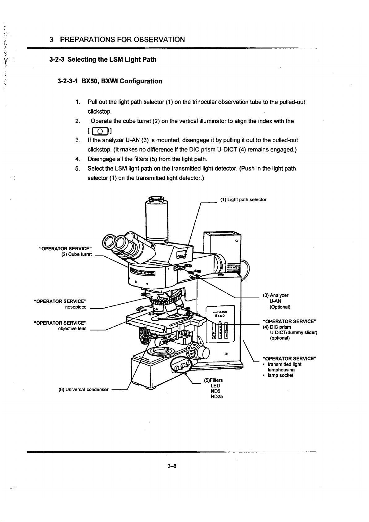
3-2-3 Selecting the LSM Light Path
3-2-3-1
BX50, BXWI Configuration
1.
Pull out
Uie
light path selector (1) on Uie trinocular observation tube to the pulled-out
clickstop.
2.
Operate the cube turret (2) on the vertical illuminator to align the index with Uie
[Col]
3. If
the
analyzer U-AN (3) is
mounted,
disengage it by pulling it out to the pulled-out
clickstop. (It makes no difference if
the
DIC prism
U-DICT
(4) remains engaged.)
4.
Disengage all the
filters
(5) from Uie light
path.
5. Select the LSM light path on the transmitted light detector. (Push in the light path
selector (1) on the
ttansmitted
light detector.)
(1) Light path selector
"OPERATOR SERVICE"
(2) Cube tunet
"OPERATOR SERVICE"
nosepiece
"OPERATOR SERVICE"
objective lens
(6) Universal condenser
(5)Filters
LBD
ND6
ND25
(3) Analyzer
U-Mi
(Optional)
"OPERATOR SERVICE"
(4) DIC prism
U-DICT(dummy
slider)
(optional)
"OPERATOR SERVICE"
• transmitted light
lamphousing
• lamp socket
3-8
Page 67

3 PREPARATIONS FOR OBSERVATION
3-2-3-2
IX Configuration
1.
Tum the light path selector (1) to select the [[ sP W setting.
2.
Set the magnification selector knob (7) to IX.
3. Operate the cube turret4o select the
[ (
Q J position.
4.
If the analyzer U-AN (3) is mounted, disengage it by pulling it out to the far clickstop. (It
makes no difference if the DIC prism
U-DICT
(4) remains engaged into the light paUi.)
5. Remove all the filters from the light
path.
6. Select the LSM light path for the transmitted light detector. (The Light path selector of
the transmitted light detector should be set at the pushed-in position.)
(6) Filter
(5) Condenser
"OPERATOR SERVICE"
objective lens
"OPERATOR SERVICE"
• transmitted light
lamphousing
• lamp socket
(1) Light path selector
"OPERATOR SERVICE"
(4) DIC prism
U-DICT(dummy sikler)
(optional)
"OPERATOR SERVICE"
(2) Cube tun-et
(7) Magnification selector knob
(3) Analyzer
IX-AN
(Optional)
3-9
Page 68

3 PREPARATIONS FOR OBSERVATION
3-2-4 Selecting the Detection Mode
When the detection mode selector slider (2) is:
• Pushed in, transmitted light is detected by CH2.
• Pulled out, transmitted light is 'detected by CHI.
Consequently, when only transmitted observation is performed, the detection mode selector
slider (2) may be set at either position.
When performing fluorescence observation simultaneously with transmitted observation, set
the detection mode selector slider at the position specified for the specimen fluochrome.
If in doubt about the setting, refer to Section 4-1-2, Adjusting the Scan Unit in the Operation
Manual and follow the prompts of the [Microscope Configuration] window.
(Refer to Section
2-1,
Scan Unit in this manual.)
Examples for reference
Observation modes
FITC + TR(Transmitted)
TRITC + TRfTransmitted)
CHI
FITC
TR(Transmitted)
*
CH2
TRfTransmitted)
TRITC
Detection mode
selector slider
Pushed in
Pulled out
[
The middle position of the detection mode selector slider is used for observation
double-stained specimens like FITC+PI.
ion of ^
(5) Filter sliders cover screws
"OPERATOR SERVICE"
(2) Detection mode (D Pinhole turret
selector slider
USm INIEKSITY
0
GOIFOCAL.
BMRIBtR
OLYMPUS
FLUOVIEW
CD
Jf
(4) ND fllter turret
(6) Laser line filter turret
(3) Banier filter slider
3-10
Page 69

3 PREPARATIONS FOR OBSERVATION
3-2-5 Disengaging the Barrier Filter
Remove all the barrier
filters
from the channel to detect transmitted light. (The banier filter
slider
(3)
should
be
at ttie pulled-out position.)
If
in
doubt about tiie setting, refer to Section
4-1-2,
Adjusting the Scan Unit in the Operation
Manual and follow ttie prompts of ttie [Microscope Configuration] window.
3-2-6 Selecting the ND Filter
Operate the ND
filter
turret (4) to engage a suitable ND
filter.
Select tiie ND
filter
in accordance witii the specimen brightness
and
level of photobleaching.
The
ND20%
filter
may be appropriate to start
with.
3-11
Page 70

4 SPECTRAL CHARACTERISTICS OF FILTERS
4 SPECTRAL CHARACTERISTICS OF FILTERS
Barrier filters
BA510IF
BA585IF
Representative filter combinations for Ar laser use
BA565IF (
DM488-
460
Ar laser Excitation
wavelength 488 nm
700
EDM570 is a dichroic
mirror for splitting
fluorescence light into
CH1/CH2.
DM488 is dichroic mirror
for excitation.
4-1
Page 71
4 SPECTRAL CHARACTERISTICS OF FILTERS
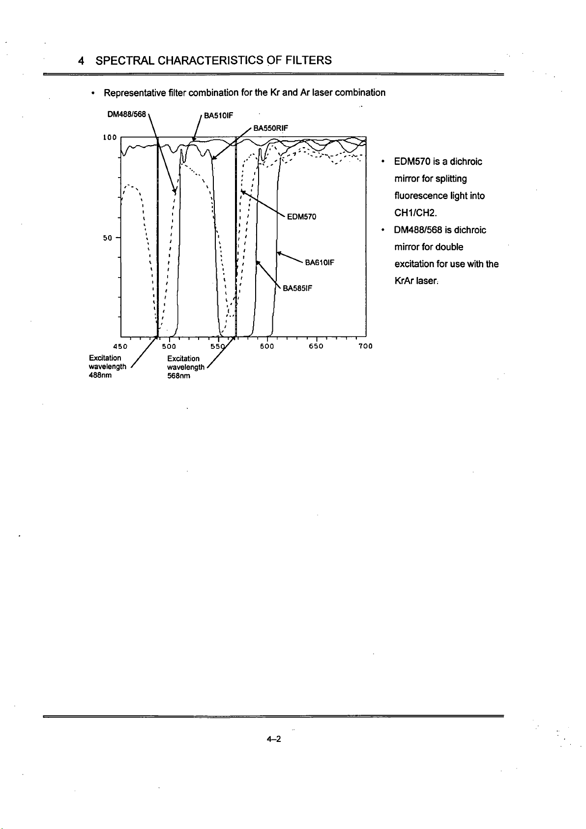
• Representative filter combination for the Kr and Ar laser combination
DM488/568 \ , BA510IF
100
50 -
450
Excitation
wavelength
488nm
EDM570 is a dichroic
min-or for splitting
fluorescence light into
CH1/CH2.
DM488/568 is dichroic
mirror for double
excitation for use with Uie
KrAr
laser.
700
wavelength
568nm
4-2
Page 72

5 SPECIFICATIONS
5 SPECIFICATIONS
-:^^M^:r^M^^M^'^:^ir^'$^
Laser unit
Scan unit
Control unit
Ar laser
Kr laser
Scan mode
Laser input
Shutter
ND filter
Scan area
Scan center position
Scan mode
Detection mode
setting
Banier filter
Confocal pinhole
Light detector
Applicable
wavelengths
Dimensions (mm)
Weight
Image input
Real-time processing
Image memory
Input memory
Image display
Image processing
Image analysis
image output
Z-movement
Dimensions (mm)
Weight
Power requirement
'^^i}:k;^:/i:l-^r!-f''!'^^U%^
5 mW output, random or linear polarization.
Air cooled Argon ion laser (488 nm)
Scan unit connection: Single mode optical fiber (3 m)
Power requirements: 100V 10A (MAX)
15 mW output, linear polarization.
Air cooled Kr ion laser (568 nm)
Scan unit connection: Single mode optical fiber (3 m)
Power requirements: 200V single phase, 20A or more
Polarized light produced by dual scanning galvanometer min-ors.
Via fiber connection
Blocks the laser when not scanning
5-aperture switchable tun-et type: 100, 50, 20,6, 0% transmission
16X12 rectangular area inscribed in the F.N. 20 boundary circle.
ZOOM:
1 to 10.
ZOOM 1.5 to 10: The center position may be moved within the X-Y
direction within the ZOOM 1 scanning area.
XY, XZ, XT, XYZ, XYT, XYZ
1.
volume projection
3-step
switchable (CH1/CH2: FL/TR, FtTFL, TR/FL)
2 filters per channel. Sharp-cut filter (filters for laser use)
Band pass filter (user-replaceable)
5-pinhole tun-et (60,100,150, 200, 300 nm)
Photomultiplier
350 - 650 nm
390(VV)x 280(D) X 197(H)
11kg
2-channel input
OFFSET: 0-100%
GAIN:
1-1
ox
/VD conversion. 4096 gradations (12 bit)
Kalman filter processing. Peak detection integration.
1024 pixel X 768 pixel X 4096 gradations
LUT alteration, tiling, zooming, 3D display.
Filter processing, image processing.
Line profile, intensity map, histogram, length, area measurement
Gradations: R, G, B, 256 gradations each
Output signal: R, G, B Sync non-interiace.
standard:
Z-motor (resolution 0.1 nm)
Optional:
Piezoelectric stage (for BX), piezoelectric nosepiece (for
IX).
stroke: 100 nm, resolution: 0.1 nm
124 (W)x 342 (D)x 382(H)
9kg
100/120/220/240V AC
1.6/1.6/0.8/O.SA
50/60Hz
5-1
Page 73

5 SPECIFICATIONS
5 SPECIFICATIONS
;:Ǥp^p5if^6^^ipjKfi|ps^?i^^
Laser unit
Scan unit
Control unit
Ar laser
Kr laser
Scan mode
Laser input
Shutter
ND filter
Scan area
Scan center position
Scan mode
Detection mode
setting
Barrier filter
Confocal pinhole
Light detector
Applicable
wavelengths
Image input
Real-time processing
Image memory
Input memory
Image display
Image processing
Image analysis
Image output
Z-movement
Dimensions (mm)
Power requirement
•li^^^li^fiiPi^a«iii«
5 mW output, random or linear polarizaition.
Air cooled Argon ion laser (488 nm)
Scan unit connection: Single mode optical fiber (3 m)
Power requirements: 100V 10A (M/VX)
15 mW output, linear polarization.
Air cooled Kr ion laser (568 nm)
Scan unit connection: Single mode optical fiber (3 m)
Power requirements: 200V single phase, 20A or more
Polarized light produced by dual scanning galvanometer min-ors.
Via fiber connection
Blocks the laser when not scanning
5-aperture switchable turret type: 100, 50, 20, 6, 0% transmission
16X12 rectangular area inscribed in the F.N. 20 boundary circle.
ZOOM:
1 to 10.
ZOOM 1.5 to 10: The center position may be moved within the X-Y
direction within the ZOOM 1 scanning area.
XY, XZ, XT, XYZ, XYT, XYZl, volume projection
3-step
switchable (CH1/CH2: FL/TR, FUFL, TR/FL)
2 filters per channel. Sharp-cut filter (filters for laser use)
Band pass filter (user-replaceable)
5-pinhole tun-et (60, 100,150, 200, 300 nm)
Photomultiplier
350 - 650 nm
2-channel input
OFFSET: 0-100%
GAIN:
1-1
OX
A/D conversion. 4096 gradations (12 bit)
Kalman filter processing. Peak detection integration.
1024 pixel X 768 pixel X 4096 gradations
LUT alteration, tiling, zooming, 3D display.
Filter prcxessing, image processing.
Line profile, intensity map, histogram, length, area measurement
Gradations: R, G, B, 256 gradations each
Output signal: R, G, B Sync non-interiace.
Standard:
Z-motor (resolution 0.1 nm)
Optional:
Piezoelectric stage (for BX), piezoelectric nosepiece (for
IX).
Sti-oke: 100 nm, resolution: 0.1 nm
124 (VV)x 342 (D)x 382(H)
100V3A
5-1
Page 74

5 SPECIFICATIONS
Microscope fi-ame
[Upright]
BX50-FLA-FVX
BXWI-FLA-FVX
[Inclined]
IX70-FLA-FVX
Stand
for
BX
Computer system
Power controller
Z-motor
Computer desk
Stand
for
BX
Anti-vibration table
forBX
Anti-vibration table
for IX, BXWI
Options
Microscope ft-ame
Trinocular
observation tube
light path selection
Objective
Microscope ft-ame
Objective
Computer
Monitor
Magneto-optical disk
No.
of
outlets
Capacity
Dimensions (mm)
Dimensions (mm)
Anti-vibration system
Dimensions
(mm)
Anti-vibration system
Dimensions (mm)
Piezoelectric
Z-stage
Transmitted light
detector
Objective
micrometer
Green HeNe laser
unit
Rubber feet
anti-
vibration table
for IX
?^-ri^^.h;M;^i^^i*^«iispedfi(a^
BX50,
BXWI
2 settings (100%
for
binocular eyepieces; 100%
for
LSM)
UIS series
IX70-FVX-F, IX70-FVXPZ-F
UIS series
Scan unit,
for
support
Specially designed
for BX
microscopes
IBM PC-AT compatible, Windows 3.11 (English)
17"
230 MB
6 / JP
(not
usable
for
the laser power supply unit, reflected light
module power supply)
100V 15A (MAX)
Microscope fine adjustment knob axis. One full tum: 100
nm
Minimum resolution: 0,1
nm*
650 (W) X 700 (D) x 670
(H)
800 (W) x 700 (D) X 670
(H)
Rubber feet
790 (W) X 667 (D) x 73
(H)
Air
1000
(W)x
700
(D)x
750(H)
Cross-control
by
extemal sensor
Stroke: 100
nm
Minimum resolution: 0.1
nm
Position reproducibility:
± 0.2 nm
2 light path settings; transmitted detection/transmitted illumination
Connected
to
the scan unit via optical fiber connection.
1
mm
100 degrees,
for
reflected light
Random polarization
1.5 mW
(543
nm)
Direct connection,
ND
filter tunet provided
1000 (W) X 680 (D) x 73 (H) (mm)
5-2
Page 75

5 SPECIFICATIONS
Operating environment
Indoor use.
Altitude: Max. 2000m
Ambient temperature: 5°C to 40t
(41*
F to 109* F)
10°C to35t (Performance guarantees)
Maximum relative humidity 80% for temperatures up to 31°C
(88'
F) decreasing lineariy tiirough 70% at 34t (93' F), 60% at
3rt(99*
F). to 50% relative humidity at 40°C (109" F)
Main supply voltage fluctuations not to exceed ±10% of the
nominal voltage.
Pollution Degree 2 (in accordance writti lEC 664)
Installation / Over voltage Category n (in accordance
virith
lEC
664)
5-3
Page 76

II mil
inie^QQinij Q ^'
Concerning
This section explains countermeasures to be taken in the
event that a problem occurs.
Please read this section and try the countermeasures before
contacting Olympus. If the problem persists, then contact
Olympus.
Page 77

Contents
Section 1 Problem Countermeasures 1-1
Page 78

Section 1 Problem Countermeasures
Section 1 Problem Countermeasures
Due to Uie usage, the functions of the system sometimes are not fully effective, although there has been
no failure; tiierefore, when a problem occurs, refer to the following chart and apply the appropriate
countermeasures.
If the same phenomenon continues to occur after the countermeasures have been taken, contact your
local Olympus dealer.
fea^AJi^,SyniptOmff;;^ia^
^:j;^.^.CountermeasureF^^'<"»
;Manual;Referencel
1.
No fluorescent light
image.
The laser is not oscillating.
Make sure ttie laser unit
power supply is tumed on
and ttie emission key is on.
Inttoduction to
Fluoview, 2-6-2.
The light path selector lever
is not set to the LSM light
path.
Set the light path selector
lever to the LSM light
path.
Hardware,
2-2,
3-1-2.
The visual observation
dichroic mirror and analyzer
are on the microscope side.
Remove the visual
observation dichroic mirror
and analyzer from the light
path.
The detector photomultiplier
voltage is low.
Use the PMT scale of the
[Acquire] panel to increase
the photomultiplier voltage.
Operation,
4-1-3-10.
The excitation light is weak.
Change to a high
transmission ratio ND fllter.
Hardware, 2-1,
3-1-6.
The fluorescent light dye
color and excitation
wavelength are not matched
(krypton/argon laser
combination).
Select a laser line filter that
matches the fluorescent light
dye color.
Refer to Operation, 4-1-2
Scan Unit Setting. Follow the
instructions in the
[Microscope Conflguration]
window.
Operation,
4-1-2.
Hardware, 3-1-7.
The fluorescent light dye
color and absorption filter
are not matched.
Select an absorption filter
that matches the fluorescent
light dye color.
Refer to Operation, 4-1-2
Scan Unit Setting, r Follow
the insti^ctions in the
[Microscope Configuration]
window.
Operation,
4-1-2.
Hardware, 3-1-5
and 4.
The confocal aperture is too
small.
Increase the aperture.
Hardware, 2-1.
The offset value is too large.
Lower the offset to an
appropriate value.
Operation,
4-1-3-10.
1-1
Page 79

Section 1 Problem Countermeasures
^^K^^^^S
1.
No fluorescent light
image.
2.
No transmitted light
image.
3. Images are disrupted.
4.
Visibility is
poor.
5. Bluning and uneven
clarity.
6. Flare is visible.
:^Kl^aus^i^Si^
The photomultiplier of the
channel set with the
detection mode setting knob
is not set.
The transmitted light
detector is not correctiy set.
The
U-ansmitted
light
filter
at
ttie microscope base is in
the light
patti.
The absorption filter is in the
light
path.
Too much vibration at the
setting location.
Fluorescent or other extemal
light is being detected.
The analyzer is in the light
path.
Scanning speed is fast
The fluorescent light dye
color and absorption filter
are not matched.
The excitation light is too
weak.
Too much vibration at Uie
setting location.
The specimen is mounted
inclined.
Non-fluorescent glass is not
being used.
g^^^'JCountemrieasureliJ^sg
Check the [Chi] and [Ch2]
check boxes of the [Acquire]
panel.
Con-ectly set ttie transmitted
light path selector knob of
Uie transmitted light
detection unit.
Correctly set the detection
mode setting slider of the
scan unit
Remove the fllter from the
light
patti.
Remove the absorption filter
in the ti-ansmitted light
detection channel of the
scan unit from the light
path.
Consult your Olympus
dealer.
Darken the room and read
the image again.
Remove ttie analyzer from
the light
path.
Lower the scanning speed to
an appropriate speed or
integrate the images.
Select an absorption filter
that matches the fluorescent
light dye
color.
Refer to Operation, 4-1-2
Scan Unit Setting. Follow the
instmctions in the
[Microscope Configuration]
window.
Change to a high
transmission ratio ND
filter.
Consult your Olympus
dealer.
Set the specimen con-ectty.
Use non-fluorescent glass.
?Manual!Reference^
Hardware, 2-1.
Operation,
4-1-3-3.
Hardware, 3-2-3.
Hardware, 2-1,
3-2-4
Hardware, 2-2,
3-2-3.
Hardware, 3-2-5.
—
•
—
Hardware, 3-1-2,
3-2-3.
Operation,
4-1-3-11,
4-1-5.
Operation,
4-1-2.
Hardware, 3-1-5
and 4.
Hardware, 2-1,
3-1-6.
—
Refer to the
microscope
instmction manual.
1-2
Page 80

Section 1 Problem Countermeasures
^^^«^
6. Flare is visible.
7. Circular flares appear in
the center of the image.
8. Blun-ing is visible.
9. Images are dari< with
excessive noise.
10.
Poor reproduction of Z
motor positions.
11.
The Fluoview software
will not start.
12.
The [Acquire] panel is
not displayed.
•^m^amm
The cover glass ttiickness is
not suitable.
The specimen is
over-
stained.
The excitation wavelength
and absorption fllter type are
not matched.
An absorption filter has not
been inserted.
The focus is not correctly
adjusted.
The con-ect pinhole has not
been selected.
The dye color is too weak.
The pinhole is too small.
The photomultiplier HV
exceeds-800.
Scanning speed is too fast
The excitation light is too
weak.
The Z position slips because
the tension of ttie
microscope coarse
movement handle is too
light
The Fluoview software has
already been started.
Anotiier application software
is operating.
The control unit is not
recognized.
ftmmQounleTmeaswe"MMi
Use a cover glass witti a
thickness of 0.17mm.
Use an appropriate dye color
or increase the offset value.
Select an absorption fllter
that matches the excitation
wavelength.
Refer to Operation, 4-1-2.
Follow ttie insU^ctions in tiie
[Microscope Configuration]
window.
Re-focus using visual
observation.
Select the correct pinhole.
Set an appropriate dye
color.
Adjust to an appropriate
position.
Use an HV of less than -800.
If
dari<,
adjust the
gain.
Lower the scanning speed to
an appropriate speed or
integrate the images.
Change to a high
transmission ratio ND
filter.
Increase ttie tension by
tuming the adjustment ring
and adjusting until the
coarse movement handle
tension increases suitably.
Press the keyboard (Alt)
and fTab) keys to switch to
Fluoview.
Shut down the other
application software and
start the Fluoview
software.
Check Uie connection
between the computer and
contt-ol unit
Tum on tiie control unit
power supply.
Turn on the AUX2 switch of
the power controller.
;iManuai,iReference^'
— •
Operation,
4-1-3-10.
Operation,
4-1-2.
Hardware, 3-1-5
and 4.
Refer to ttie
microscope
instiojction manual.
Hardware, 2-1.
—
Hardware, 2-1.
Operation,
4-1-3-10.
Operation,
4-1-3-11.
Hardware, 2-1,
3-1-6.
Refer to the
microscope
instmction manual.
"
Operation,
2-1-1.
Inti-oduction to
Fluoview, 2-6-2.
1-3
Page 81

Section 1 Problem Countermeasures
teg5l3i?^tSymptomMs4;!Si;#Si
13.
The scale of tiie [Z
Stage] in the [Acquire]
panel is not woridng.
14.
The fine movement
handle of the
microscope will not
move or moves with
difficulty.
15.
Images cannot be saved
to disk.
16.
Images are not output to
the printer.
17.
The mouse pointer does
not move when the
mouse is moved.
The Z stage (Z revolver)
motor is not being excited.
The Z stage (Z revolver)
motor is being excited.
The disk has not been
formatted (in the case of a
floppy disk or photoelectric
disk).
The photomagnetic disk is
not recognized.
Insufficient empty space on
Uie disk.
The printer is not being
recognized.
The software is
misoperating.
^!/i^seountemiMisdre-^<|?s^i
Check the [Engage motor]
check box of ttie [Z Stage]
panel.
Clear the [Engage motor]
check box of ttie [Z motor]
panel in the [Acquire] panel.
Format the disk.
Make sure the photoelectric
disk power supply is on.
Check ttie cable
connections.
Increase the available
space by deleting
unnecessary data or use a
new disk (formatting is
necessary).
Make sure the printer power
supply is on.
Check the cable
connections.
Press the keyboard +(ctri)
( Alt 1 -^ (Dellete ] keys and
observe the messages that
appear. Shut down
Fluoview.
Shut down Windows and
restart the computer.
IManuaHReferenbe^
Operation,
4-1-3-8.
Operation,
4-1-3-8.
Operation,
Appendix
A.
Refer to Uie
photoelectric disk
instruction manual.
Operation,
Appendix
A.
Refer to the printer
instruction manual.
Operation,
2-1.
1-4
 Loading...