

Page 1
olympus
microscope
scanned
by
J.
G.
McHone
• t .
21
Nov
09
NOT
FOR
SALE
zns
ructzons
Olympus
-Tokyo
Page 2
scannedbyJ.
G.
McHone 21
Nov
2009
forpersonal use
only,
not
for sale
OLYMPUS MICROSCOPE MODEL
FH
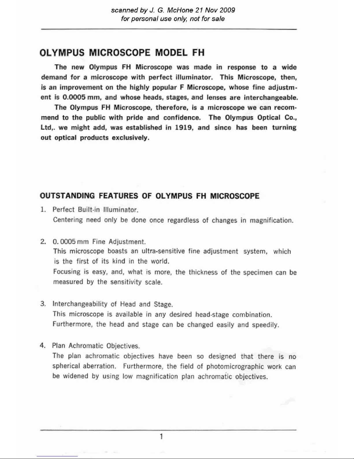
The new Olympus
FH
Microscope was made
in
response
to
a wide
demand
for
a microscope
with
perfect
illuminator.
This Microscope, then,
is an improvement on the
highly
popular F Microscope, whose
fine
adjustm-
entis0.0005
mm, and whose heads, stages, and lenses are interchangeable.
The Olympus
FH
Microscope, therefore, is a microscope we can recom-
mend
to
the public
with
pride and confidence. The Olympus Optical Co.,
ltd,.
we
might
add, was established in 1919, and since has been
turning
out
optical
products exclusively.
OUTSTANDING FEATURES
OF
OLYMPUS
FH
MICROSCOPE
1.
Perfect Built·in Illuminator.
Centering need only
be
done once regardless of changes in magnification.
2.
0.0005
mm
Fine Adjustment.
This microscope boasts
an
ultra-sensitive fine adjustment system, which
is
the first of its kind in the world.
Focusing is
easy,
and, what
is
more, the thickness
of
the specimen
can
be
measured
by
the sensitivity scale.
3.
Interchangeability of
Head
and
Stage.
This microscope is available in
any
desired head·stage combination.
Furthermore, the
head
and stage
can
be
changed easily
and
speedily.
4.
Plan
Achromatic Objectives.
The
plan achromatic objectives
haye
been
so
designed that there is no
spherical aberration. Furthermore, the field of photomicrographic work
can
be
widened
by
using
low
magnification
plan
aChromafic objectives.
Page 3
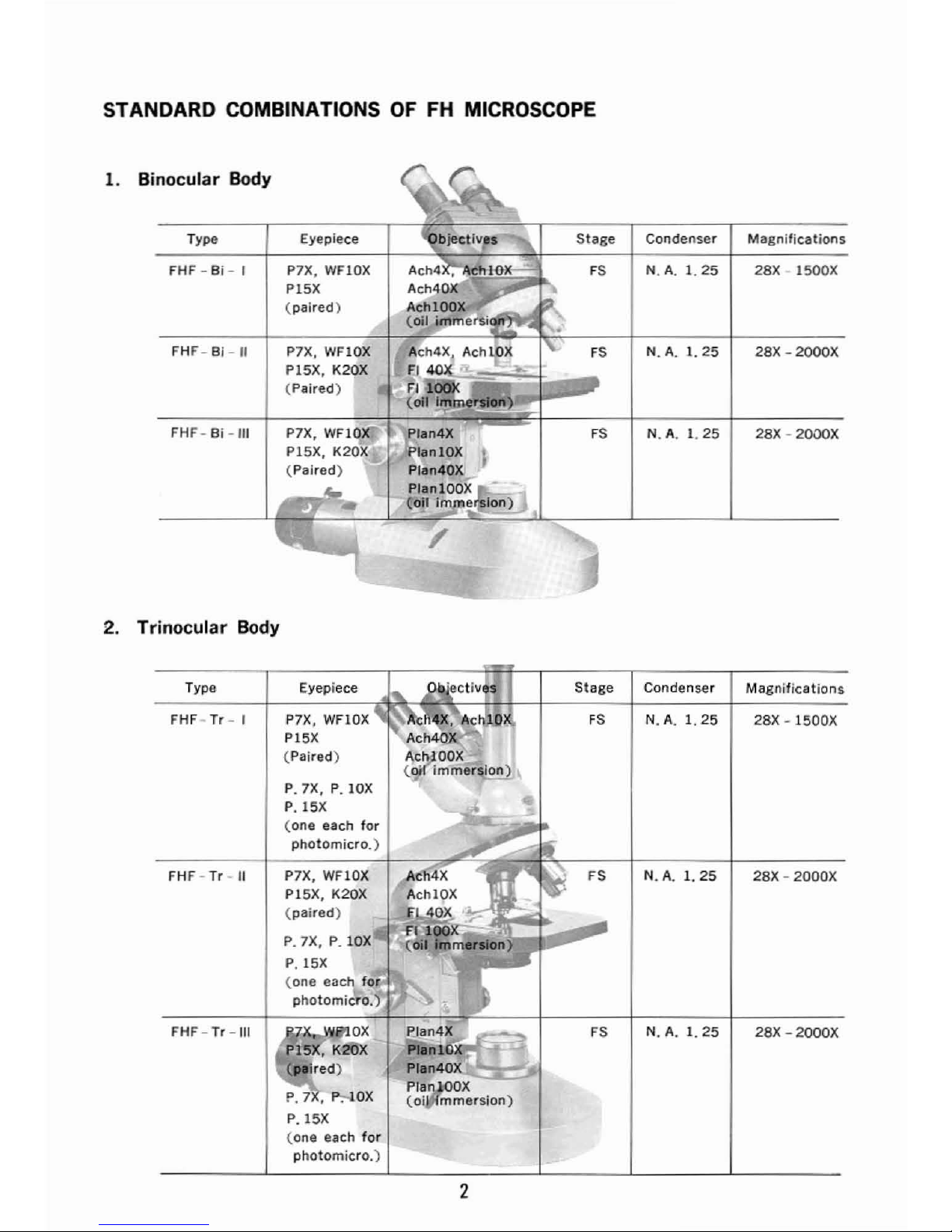
STANDARD COMBINATIONS
OF
FH MICROSCOPE
1.
Binocular
Body
Type
Eyepiece
Stage
Condenser Magnifications
FHF - Bi - I P7X, WFlOX
FS
N.A.I.25
28X·1500X
PI5X
(paired)
FHF - Bi -
II
P7X, WFIOX
FS
N.A.1.25
28X -
2000X
PI5X,
K20X
(Paired)
FHF- Bi
-III
FS
N.
A.I.25
28X -
2000X
2.
Trinocular
Body
Typa Eyepiece
Stage
Condenser
Magnifications
FHF·Tr- I P7X. WFlOX
FS
N.A.I.25
28X
·1500X
PI5X
(Paired)
P.7X,
P.lOX
P.
15X
(one
each
for
photomicro.)
FHF -Tr-
II
P7X, WFIOX FS N.A.1.25
28X -
2000X
PI5X,
K20X
(paired)
P.7X,
P.IOX
P.
15X
(one eac
10<
photomicro.)
FHF -
Tr-III
PJan4X
FS
N.A.1.25
28X
-2000X
P1anll'l
Plan40X
P.7,f':--.IOX
Plan
;(lOX
(oj
mmersion)
P.
15X
(one each
for
photomicro.)
2
Page 4
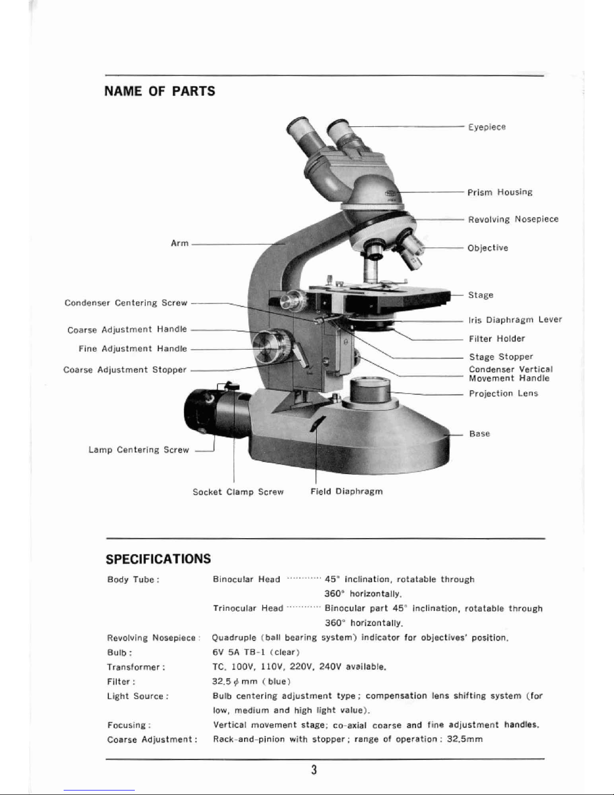
NAME
OF
PARTS
Arm
...,
Condenser Centering Screw
---~......J
Coarse Adjustment Handle
----_
Fine Adjustment Handle
-----
Coarse
Adjustment
Stopper
------
Lamp Centering Screw
Socket
Clamp Screw
SPECIFICATIONS
'r----------
Eyepiece
,--------
Prism Housing
...-....
,.----
Revo!vinS NosepIece
~----
Objective
Stage
r------
Iris Diaphragm Lever
"------
Filter Holder
'-------
Stage
Stopper
Condenser
Vertlca
I
.----------
Movement
Handle
Projection Lens
Sase
Field
Diaph"~gm
Body
Tube:
Revoll/jng
Nosepiece:
BUlb:
Transformer:
Filter:
Ught Source:
Focusing;
Coarse
Adjustment:
Binocular Heed
-,
45ftInclination, rotatable through
3600horizontally.
Trinocular Head Binocular
part
45ftinclination, rotatable through
360"
horizontally.
Quadruple (ball bearing
system)
indicator for obJectives' position.
6V 5A
TB-l
(clear)
Te.
IOOV.
IIOV.
220V.
240V
aYallable.
32.5~mm
(blue)
Bulb centerIng
adjustment
type;
compensatIon lens Shifting system
(for
low, medium and high
light
value)_
Vertical
movement
stage; co-axial coarse and fine
adjustment
handles..
Rack-tlnd-pinion with
stopper;
range of
operation;
32.5mm
3
Page 5
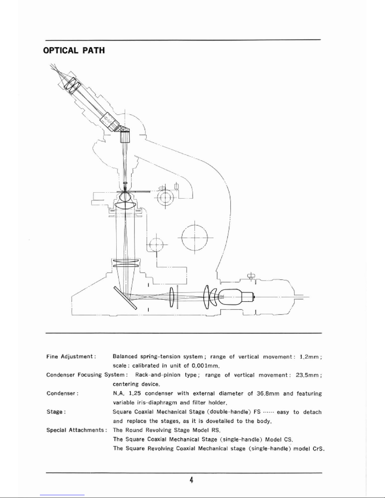
OPTICAL PATH
~--
<-----~
----
----
LL_~
__
/
Fine
Adjustment:
Balanced
spring-tension
system;
rangeofvertical
movem@nt:
1.2mm;
scale;
calibratedInunitofO.OOlmm.
Condenser
Focusing
System:
Rack-aod-pinion
ty~e;
range
of
vertical
movement:
23.5mm;
centering
device.
Condenser:
N.A.
1.25
condenser
with
external
diameter
of
36.8mm
and
featuring
varlabre
iris-diaphragm
and
filter
holder.
Stage:
SCluare Coaxial Mechanical
Stage
(double-handle)
F'S.-....
easy
to
detach
and replace
the
stages,
asit15
dovetailedtothe
body.
Special
Attachments:
The Round Revolving
Stage
Model
RS.
The SCluare Coaxial
Mechanical
Stage
(single-handle)
Mod@1
es.
The
Square
ReYolvlng Coaxial Mechanical
stage
(single-handle)
model
erS,
4
Page 6
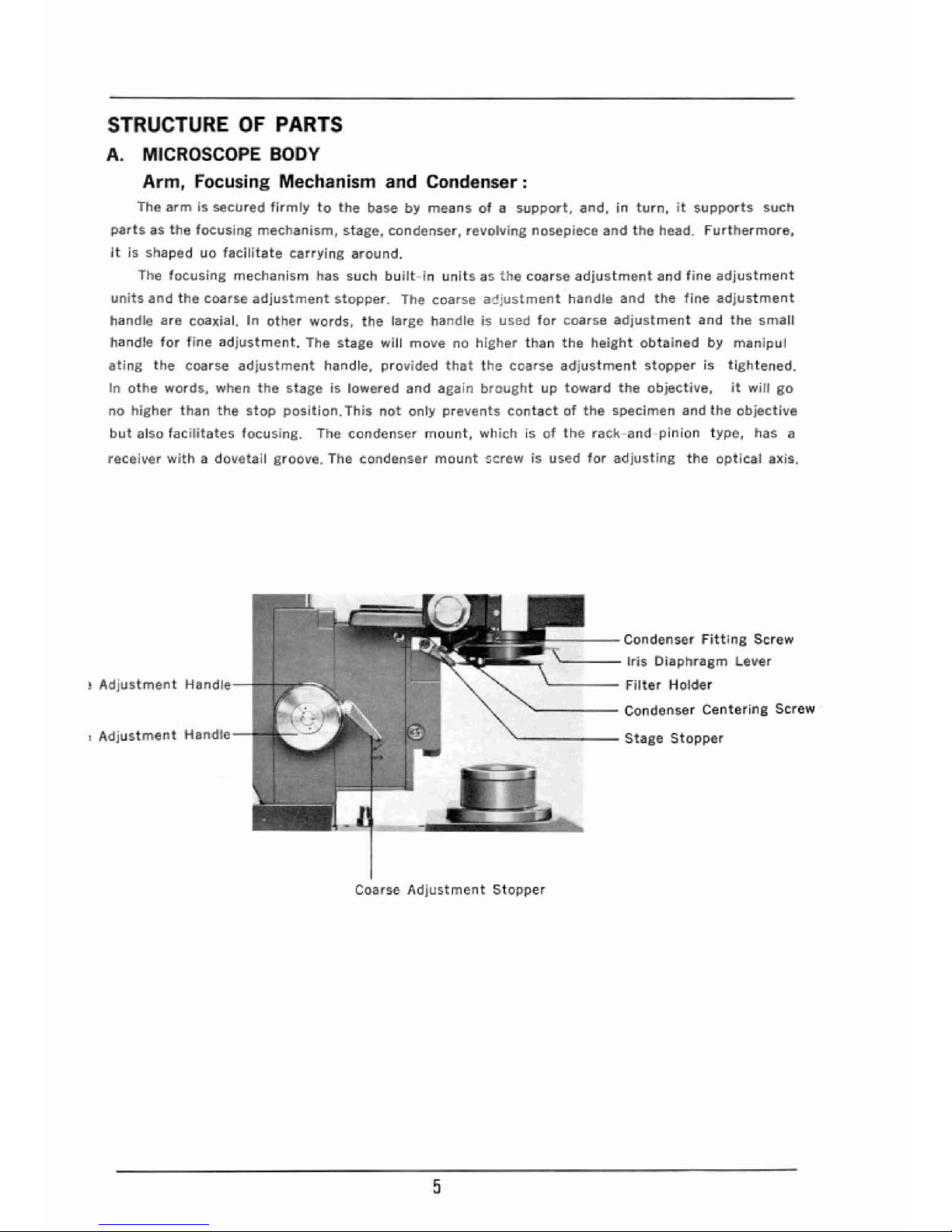
STRUCTURE
OF
PARTS
A.
MICROSCOPE
BODY
Arm,
Focusing Mechanism and Condenser:
The
armissecured
firmly
to
the
basebymeansofa
support,
and.inturn,itsupports
such
partsasthe
focusing
mechanism,
stage.
condenser,
revolving
nosepiece
and
the
head.
furthermore.
It
is shaped
uo
facitrtate
carrying
around.
The
focusing
mechanism
has such
builtinunrts35the
coarse
adjustment
and
fine
adjustment
units
and
the
coarse
adjustment
stopper.
The coarse
adjustment
handle
and
the
fine
adjustment
handle
are
coaxial.Inother
words.
the
large
handleisused
for
coarse
adjustment
and
the
small
handle
for
fine
adjustment.
The
stage
will
movenOhIgher
than
the
height
obtained
by
manipul
ating
the
coarse
adjustment
handle,
provided
that
the
coarse
adjustment
stopper
is
tightened.
In
othe
words.
when
the
stageislowered
and
again
brought
up
toward
the
objecti\le.
it
will
go
no
higher
than
the
stop
position.
This
not
onl)l
pre~ents
contactofthe
specimen
and
the
objective
but
also
facilitate5
focusins.
The
condenser
mount.
which i5ofthe
rack-and-plnlon
type,
has
it
recei~er
withadovetail
groove. ThB
condenser
mount
l:;crewisused
for
adjusting
the
optIcal
axis.
~
Adjustment
Handle-
....
+.,..~!LJ
I
Adjustment
Handle
----Condenser
Fitting
Screw
'----
Iri5 Diaphr.8gm Lever
'----
Filte, Holde,
"------
Condenser
Centering
Screw
'-------
Stege
Stopper
Coarse
Adjustment
Stopper
5
Page 7
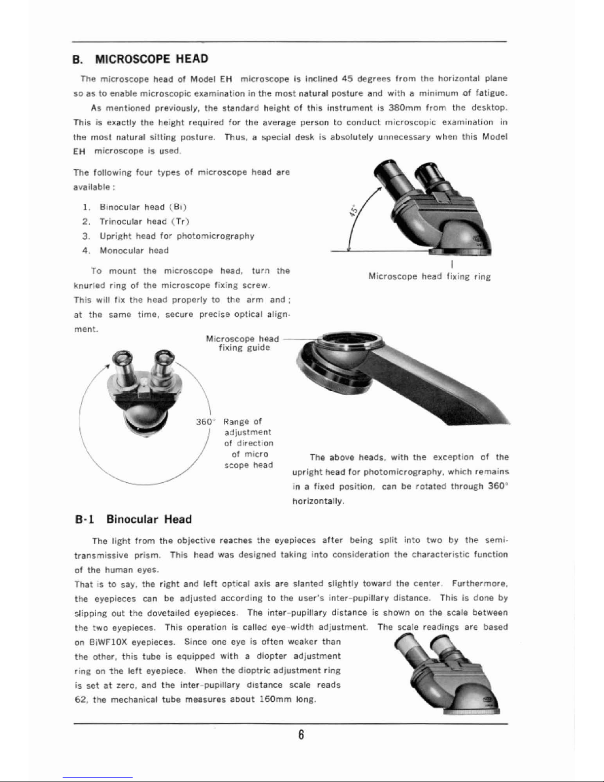
B.
MICROSCOPE
HEAD
The
mitroscope
headofModel
EH
microscopeisinclined
45
degrees
from
the
horizontal
plane
so astoenable
microscopic
examinationinthe
most
natural
posture
and
with
is
minimum
of
fatigue.
As
mentioned
previously,
the
standard
heightofthis
instrumentIs380mm
from
the
desktop.
Thisisex.actly
the
height
required
for
the
average
persontoconduct
microscopic
examination
In
the
most
natural
sitting
posture,
Thus, a special
deskisabSOlutely unneceSSary when
this
MOdel
EH
microscope is used.
The
following
four
typesofmicroscope
h~ad
are
available;
1.
Binocular
head
(Bi)
2. Trinocular
head
(Tr)
3.
Upright
head
for
photomicrography
4.
Monocular
head
To
mount
the
mu;:roscope head,
turn
the
knurled
rinBofthe
microscope
fix.ing
screw.
This
witt
fix
the
head
properly
to
the
arm
and;
at
the
sam~
time,
secure
precise
optical
align-
ment.
Microsc.ope
h@:ad
fixing
guide
3600Ranso
of
adjustment
of
direction
01
micro
scope head
B·1
Binocular Head
I
Microscope
head
filcing
ring
Ttle above he.ads,
with
the
exception
of
the
upright
head
for
photomicrography,
which
remains
In a
fix@d
position,
can be
rotated
through
360
0
horizontally,
The
light
from
the
objective
reach@$
the eyepieces
after
being
split
into
two
by
the
semi.
transmissIve
prism.
This
head was
designed
taking
Into
consideration
the
Characteristic
function
of
the
human
eyes_
Thatisto
say. the
right
and
left
optical
axis
are
slanted
slightly
toward
the
center.
Furthermore,
the
eyepieces can be
adjusted
according
to
the
user's
inter-pupillarv
distance.
Thisisdone
by
sHpping
out
the
dovetailed
eyepieces. The
inter-pupillary
distanceIsshownOnthe
scale
between
the
two
eyepieces. This
operationiscarr@d
eye-width
adjustment.
The scale readinBs are
based
on BiWFlOX eyepie:ces. Since one
e~e
is
often
weaker
than
the
other,
this
tubeisequipped
withadiopter
adjustment
ringonthe
left
eyepiece. When
the
dioptric
adjustment
ring
is
setat2.ero,
and
the
inter-pupillary
distance
scale
reads
62,
the
mechanical
tube
measures
aDoul
160mm
long.
6
Page 8

B·2
Trinocular
Body
The
trinocular
head
consistsofbinocular
head and
upright
head
for
photomic.rography.
The
photo,trapller
can actually see
what
he
is
photographing
since
it
inCO(PO~iJtes
a
mechanism
to
switch
the light
pateh
alternately
for
direct
observation
and
photomicrographic
work.
The
binocular
head is
equipped
withiJdioptric
adjustment
ring
andanInter-pupHlary
distance
scale,
Straight
tube
for
photomicrography
prism
shiWng
knob
When the
prism
shlftlng
knob
is pUlled
outward
as
shown
in the above
photo.
the
prism
locks
into
position
(0)
diagram)
and
the
pathofraysisdirec-
tedtolhe
upright
head
for photomicrographic work.
A
PUSh
in
of
the
knob
almost
instantly
returnS
the
prism
to
its
original
position
(@
diagram).
ThIs unique
mechanism
(one-knob
operation)
permits
direct
observation
and
photomicrographic
work
alternately
with
a minimum loss
of
time.
rn
Pathofraysatthe
time
W
of
photomicrography
00
Path
of
rays
at
the
time
of
direct
observation
Inter-pupillary
distance
scale
Dioptric
adjustment
ring
set
at
zero
B-3
Upright
head
for
photomicrography
In caseofmicroscopes
featuring
monocular
inclined headorbinocular
head,
the
standard
microscope
head
must
be
interchanged
with
an
upright
head
when
conducting
photomicro·
graphic
work.
The
photomicrographic
appara·
tus
must
be
mounted
on
this
upright
head.
B-4 Monocular Head
7
Page 9

C.
STAGE
There
Ire
four
typesofstages
available
for-
Model
F'H:
o Square coaxial
mechanical
stage
(double
handle)
FS:
o Square
revolving
coaxial mechanical
stage
(single
handle)
erS
o Square coaxial
mechanical
stage
(single
handle)
CS
o Round
revolving
stage
RS
The square
cOClxial
mechanical
stage
fSisstandard
equipmentofthe
fH
Microscope.
C·l
Square Coaxial Mechanical
Stage
FS
ThIs square
stage
can be detachedatwill sinceitis
dovetailedtothe
main
body.
The
specimen
can be moved
by
meansofhandles
found
on
both
sidesofthe
stage.
For
forward
and
backward
movementofthe specimen, a
large
handle
(raCk-aod-pinion)
is
used,
andasmall
handle
(lead
screw)
is used
for
lateral
movement
Th{J
surfaceofthe
stage
can
be made levelbYremoving
the
Clip.
Two
slide glasses
canbeplacedonthe
specimens
side
by side.
Thisisextremely
convenient
when
comparing
two
specimensatthe
same Ume.
Lateral
movement
handle
Lateral
movement
scale
----'l---=
forward
and
backward
movement
handle
Forward
and
backward
movement
scale
Lateral
movement
handle vernier
Forward
and
backward
movement
handle
8
Page 10

P.
lOX
Binocular
head
P 15X
Eyepieces
Photo
lenses
~
Monocular
inClined head
MODEL
FH
VARIED COMBINATION
OF
PARTS
Ob)ecti\lu
Round
stage
RS
Abbe
condensers
N A 1.25
Page 11

-
P.
7X
Trlnocular
head
Ugright head
Square
mechanical
stage
(single handle)
CS
N.A.I.40
Square
revolving
mechanical
stage
(single handle)
C,S
SWing-outN.A.
0.25-0.9
Square mechBnical stage
(double handle)
FS
Page 12

C-2
Square Revolving Coaxial Mechanical Stage (single
handle)
CrS
This
stageisfixed
firmly
to
the
bOdYofthe
microscope.
and on
Its
surfaee,
there
is a
cross
movement
clip. The
specimen
is
shifted
by
means
0"acoa;a:iar
type
forward
and
backward
movement
handle and
lateral
movement
handle on
the
right
sideofthe
stage. The
tormer
Is
operated
by
meansofa rac.k-and-pinion. whereas
the
latterIsmanIpulated
by
means
of
a lead
screw.
The
workIng
ranseofthe
handles
are:
Forward
and
backward
27mm
Lateral
_ _
70mm
Each
handle
has a scale
(0-30.
40-110)
and a
vernier.
Rotation;
After
st!'tting
the
slide glass in
position,
the
centerofthe
slide
glassisbrought
Into
line
with
the
optical
axis.
Then
the
sta86
j!i
rotated
horizontally.
The stage
rotates
about
220·
to
clockwise,
and
about
200:.tocounter-cloc:kwise.
Rotation
can be
stoppedbymeans
of
the
stage
stopper,
Rotating
220·
Lateral
movement
handle
~
Forward
and
backward
movement
handle
C-3
Square Coaxial Mechanical Stage (single handle)
CS
This
mechanical
stage can be
operated
byasingle
handle
which
consistsofa
rack-aod-pinion
for
forward
and
backward
movement.
and a lead
SCrew
for
lateral
movement
Lateral
movement
scale
Forward
and
backward
movement
handle
Forward
and
backward
movement
scale
lateral
movement
t1andle
11
Page 13

C-4
Round Revolving Stage
RS
The
round
revolving
stage
consistsoftwo
stages.
The
lower
stage
is
fixed
to
the
stage
mount
On
the
main
body.
The
upper
stage slides over tne
lower
stage
horizontally.
Sliding Is donebyoperating
the
left-
and
right-
side
fine
adjustment
handles
by
turns.
Furthermore,
the
upper
stage
can be
rotated
through
360"
horizontally
by
pressing
the
knurl
part
on the
rimofthe
stage.
Clip
Stage fine movement handle
How
to
Fix Stage
to
the
Body
The Olympus FH
stases
have beensomade
that
they
can be
easily
fixedtothe
main bodY.
The
four
stagos rs. CrS,
CS
and
RS.
eaen
of
which is used
fer
a specifiC purpose _ are
Jnterchangeable.
1.
Firstofall,
the
condenserisloweredasfaraspossiblebymeansofthe
condenser
handle.
2.
The
stage
mountisalso
lowered
l!I$
faraspossiblebyturning
the
coarse
adjustment
handle,
3.
In
the
caseofFS. CrS
and
CS
stages,
the
clip
is
moved
forward
as
far
as
possible
by
manipulating
the
forward
and
backward
maven
lent
handre.
4.
Next,
the
stage
guide
(,A)
is
slowly
inserted
Into
that
of
the
main
body
(8)
with
the
lock-rever
up.
The stage
must
be so
Inserted
thatitis
parallel
with
the
main
bodY, Care
must
be
taken
not
to
crash
the
top
lens
of
the
condenser
with
the
stage
during
this
operation.
5.
Finally,
the
stage
firmly
fixedtothe
main
bodybymeansofthe
rock-lever.
(A)
lock-lever
12
(B)
Page 14

D.
REVOLVING NOSEPIECE
The revolvlllB
nosepieceofModel
FH
featuresaball-alld-socket
revolving
system
with
four
objective
mounts.
A
knurled
rillS is
provided
for
slip-free
and
smooth
manipulation
of
the
nosepIece.
By
meansofthe
large
built-in
spril'lg
and
groove,
the
objll:!e:.tive
s.ets
into
Position
ac.curately.
maintaining
proper
optical
alignment.
ihe
upper
'Surfaceofthe
(evolverismarked
with
the
letters
A,5,C,
D in
ordertoShow where tne
objectives
s,hould be
fixed.
'A'i5far
4X,
'8'
fOr
lOX.
'C'
for
40X,
and
'0'
for
lOOX. In
this
way,
the
position
of
the
objectives
do
not
change.
Furthermore,
the
observe..can
tell
which
objective
is
being
u5ed while
conducting
observation.
B
(lOX)
A
(4X)
E.
BASE AND ILLUMINATOR
Letter
specifying
position
of
differ8nt
objective
Tile
base
not
only
supports
the
microscope
but
also has
built-in
illuminator.
The
light
source
unitisfixedtothe
basebymeansoffitting
screws.
Switch
over
the
Or'st
compensation.
tens
according
to
the
mCli811ification
of
the
objective
being
used.
The
compensation
lens
shiftll1g
lever
Is used
for
the
following
purposes.
l
(Low)
objective
4X
or
lass
M
(Medium)
objective
lOX
and
20X
H
(High)
objective
40XormOre
Socket
Clamp 5cr'ew
lamp
Centering
Screw
Field
Stop
13
Projection'
Lens
Page 15

lens
(Low)
L-
__
M
(Medium)
(4X
or
'.ss)
6V.5A
\ I
~
.~----J
f '
1-:--<.
i
I·_·-J
I
~
ICOlYJ
I~
-/
')
Lr--j-<-----------'L
---J
Field
stop
For
low
magnification
For
high
magnification
(40XormOl'"e)
EFFECTIVE ILLUMINATION
PriOrtoconducting
microscopy,itisofvery
importance
to
check
whether
appropriate
and
effecth"e
lightinSisdirectedtothe
specimen.
Thatisto
say,
the
observer
should seeifthe
ray
of
light
emitted
from
the
illuminatorOrmirror
followsacentral
path
leadinstothe
obiective
and
eyepieces.
This
can be donebylook
ins
into
the- eyepiece tube
after
roughly
focusing
a 40X
objective
or
lOX.
objective
and remo\lling
the
eyepiece.
If
the
light
from
the
light
source
unit
illuminates
throughout
the lens surfac.e evenly without: any
eccentricity,
it
means
that
proper.
effective
lightingisbeins rendered.
E\lIenifthe
lightisnot
eccentric., only
the
centerofthe
lens
is
often
illuminated
brightly.
This
means
that
the
condenserisnotinthe
proper
position.
This
canbecorrectedbyadiusting
the
positionofthe
condenserbymovingitup and
down.
However.
it
should be
notea
that
inaccurate
focusing
produces
the
same
phenomenon.
Even
the
slightest
mistake
can
throw
the
optic
path
off
center.
To
illustrate,
the
observer
should
not
even
touch
the
mirror
sinceitresults
ifl
poor
illumination.
Furthermol'e,
wnen
the
image appearStomove
off
the
center
while
manipulating
the
fine
adjustmeflt
handle in
the
COurse
of
securing
focus.itmeans
that
the
pathofraysisnot
aligned propel'ly. In
this
case,
lighting
must
be
readjusted
in accordance
with
the
fore,going procedures.
CENTERING
OF
LIGHT
Centel'"ingoflight
from
the
light
SOUl'eeisessentialtoordinary
micl'oscopy
and
mlcropl'loto·
sraphy,
The
followl"g
procedul'"es
permit
to
Obtain soo(J
centeringofligl1t.
1. Focus
the
specimen
with
lOX
objective.
2. Close
both
Il'i$ diaphragmoftne
condenser and field
stopofthe
illuminator,
Bring
~Ield
stop
(8
small
circleofstop-lisht)
into
focus
by
moving
the
condenser
up and down.
14
Page 16

3. Set field
stop
(stop-light)
at
the
centerofthe field by
manIpulating
two
condenser
centering
screws.
4.
Open field
stop
slowly so
that
an
entire
field
can
be
seen.
5.
Remoye
the
eyepiece
from
the
e}'epiece
tube,
and
open
iris
diaphragm
slowlY, While looking
into
the eyepiece
tube,sothat
an
entire
field
can be
lighted.
6.
By
adjusting
the
lamp
centering
screws
(2
screws)
of
the
lamp
house,
set
the
image
of
filamentatthe
centerofthe
field.
7. Replace the eyepiece. and
start
your
microscopic
examination.
NOTES:
(1)
When
low
magnification
objective.
particularly
4X
objective,
Is used,
the
field
is
often
illuminated
unevenly. In
this
case,
adjust
lightingbyoneofthe
following
manners.
(s)
Loosen
the
socket
clamp
sCrew and move
the
socket
back
and
forth
slowly, while
looking
into
the eyepiece tube, and
fbe
the
socketata
position
where an even
light
can be obtained.
(b)
Remove
the
condenser and replaceItafter
takinB
off
the
top
tens. In
other
words.
use
the
condenser
without
the
top
lens.
(c)
Put
ground
glassonthe
projection
lensofthe
illuminator.
(2)
Condenser.
The
numerical
apertureofcondenser is
1,25
when
011
is used
for
oil
immersion
microscopy.
otherwiseitis about N.
A.I.
0
......
0.9,
and N.
A.
0.5
without
the
top
lens.
PROCEDURE
FOR
ADJUSTING THE COARSE ADJUSTMENT HANDLE
Generally speaking,
the
coarse
adjustment
nandles
are
tight.
This.ofcourse,
means
that
movement
is heavy.
However.
this
can be remedied easily by
gripping
the
right-and
left-side
handles as
illustrated
and
turning
theminthe
opposite
direction
SImultaneously. In
most
cases,
the
coarse
adjustment
handles
should be
moreorless
tight
rather
than loose.
WORKING DISTANCE AND PAR·FOCAL
The revolving nosepiecetowhich
the
objectives
are
attached,
has been
so
designed
that
as
long as one
objective
has been
focused
properly
the
others
can
be
focusedbymeansofthe
fine
adiustment
handle. The
distance
from
the
tipoflow
magnificiltion
objectlvetothe
specimen
is
considerably
100l3er
than
that
from
high
magnification
objective.
The
distanceisshortestinthe
caseofoil
Immersion
objective,
When
the
reVOlving nosepiece is
rotated,
after
focus
is secured
with
one
of
the
objectives.toSWitch
the
magnification
from
onetothe
other,
1nr Instance,
to
the
oil
immersion
objective.
thereisno
dangerofthe
tipofthe
lens
touching
the
specimen.
In
other
words,
mictMcopic
examination
canbeconducted
immediately
after
manipulating
the
fine
adjustment
handle.
15
Page 17

Focus
at
first
by
utilizing
lOX
objective.
The
distance
between
the
objective
and
the
microspecimeninthis
case
will
be
approximatelv
5.6mm.
Even
when
lOQX
objective
is
set
to
viewing
position.
it
will
not
collide
with
the
microspecimen_
The
distance
will
thenbeaboutO.t4mm.
INSTRUCTION
FOR
USING
OIL IMMERSION OBJECTIVE
Before
using
oil
immersion
objective.
secure
focus
by
using
low
magnifIcation
objective.
Apply
a
dropofcargille
011oranIsoletothe
surfaceofthe
specimen,
Also
apply
cargille
oiltothe
oil
immersion
objective_
As
we have already
mentioned,
the
oil
immersion
objective
will
not
touch
the
specimen
when
the
revolving
nosepiece
brings
it
into
position
over
the
specimen.
After
focusing
the
lensbymeansoftHe fine
adjustment
handle,
microscopic
examination
can be
carried
out
without
any
lossoftime.
After
examination.
cargille
oil
left
on
the
oil-
immersion
objective
must
be
thoroughly
wiped
off
with
gauze
dippedinxylene.
Otherwise.
the
lens
will
SOOn
become
useless, Crean
gauze
is
sufficient
to
wipe
off
anisole.
Place a
dropofcargille
oil
or
anisoleonthe
microspecimen
Apply
carsitle
oil
to
the
tip
of
the
oiHmmerson
oblctive
CAUTION
Microscopes
are
extremely
allergictomoisture
and
dust.
Since
both
moisture
and
dust
are
foundinmost
laboratories,
microscopes
should
be
kept
in
containers
imme:diately
after
use.
If
thisisnot
possible,
they
shouldbecovered
with
the
enclosed
vinyl
dust
cover.
As
for
objectives
and eyepieces.itis
best
to
keep
them
in
desiccators.
Falling
thls.
they
should
be
keptincases
containing
such
desiccants
as silica 8el.
After
the
e)'epiece has been
removed,
the
e,yeplece
tube
shouldbecovered
with
the
enclosed
cap.
Bynomeans
shouldamicroscopebetaken
apart
for
repairs.
This
should
be
lefttoexperts.
And,
of
COurse.
microscopes
must
alwa,ys be
kept
clean. Fine
dust
on
parts
that
cannot
be
reachedbythe
hand
shouldbeblownorwiped
off
by
meansofair
blowerorclean
feather.
16
Page 18

ACCESSORIES
Small
Photomicrographic
Apparatus, PM-6
The
PM-6ISa
photomicrographic
unit
designed exclusively
for
taking
full-size
photographs
on
a
35mm
film. Fits all typesofbiological and metallur'gical microscopesofall makes.
o
Shutter
speed:
S,
1-1/50
sec.
o Size
of
image;
24mmx.36mm
o SpBcimen can be observed whlte
photographing
o Has
insertion
opening
(or
photo
cellofphotomicrographic
exposure meter'.
o Aio'allable
for
all eyepieces
except
5X
power.
o
Shock-proof
shutter
prevents
shutter
IJlbration and
insures
no
blurred
pictures.
o Magnification on the
film
plane:
about
If3Xoftotal
magnificationsofmicroscope.
Phase
Contrast
Equipment, PA •
PB
The
bright
field
observation
methodofmicroscopic
examination
can
not
be
used
for
examining
colorless,
transparent
specimens
since such
specimens
lack
contrast.
The phase
contrast
equipment,
therefore,
was designedtoprovide
such specimens
with
COntrast and thus
make
examination
of
tivlng
bacteria,
c-ells and
tissue
possible.
Two
kindsoflight
pass
through
specimen
namely,
undeviated
light
and
deviated
light.
Deviated
lIght
is
M wave
length
slower
than
undevi.ated
light.
Contrast
can be
strengthened
through
light
interferencebymakins
undeviated
light
!4-
!Nave
length
faster
or
srower. This
meth04
is
highly
convenient
for
observationotthe
ecologyofthe
specimen
sinceiteliminates
such
trou·
blesome
procedures
as
dyeing
the
specimen.
The
Olympus
phase
contrast
equipmentishighly
prized
today
sinceithas widened
the
scopeofbIologIcal
microscopic
e)(:amlnatlon. What is
more.
Itiseasytohandle.
Contents
of
Phase
Contrast
Equipment
Set.
model
PA
Phase
Contrast
Objectives
for
4
different
co-
ntrasts
each
with4different
magnifications
(total
of
16
objectives)
:
PL
lOX, 20X, 40X. 100X
(oil
Immerson)
PLL lOX, 20X, 40X, 100X
(oil
immerson)
NH
lOX, 20X, 40X,
IOOX
(oil
immerson)
NM
lOX, 20X, 40X, 100X
(oil
immerson)
Phase
contrast
turret
condenser,
Centering
Telescope
(CT),
Green
filter
(outer
diameter
32.5mm)
17
Page 19

model
PB
One
setofPf1ase.
Contra-s!
Objectives
of
the
above
mentioned
4
contr.ast~
(PL,
PLL.1NH.
NMJ.
Als:J
contains
Ph;;lse
contrast
turret
condenser,
c.entering
telescope
(CT), and
green
filter
(outer
diameter
32.5mm).
Note;
Contr'3st;
P'L
Positive
Low
PLL
Positive
low low
NH
Negative
High
NM
Negative
Medium
Lens Container
ThiS
isacontainer
specially
made
for
miCfOScOPO
l@nS8S.
Withadesiccant
(silica
gel)atthe
bottom
of
the
container,
lenses
canbekept
completely
freeofmoisture
and
dust.
The
plastic
top
permits
to
check
the
lenses
from
outside
without
r'emolo'ing
the
top,
anditIs
very
convenient
to
keep
the
lenses in order"
Capacity:
7 lense'S
(upto57mm
hish)
3
filters
(upto33mm
in dia. and
3.5mm
thick)
Plan
Achromatic
Objectives
fllew and
originally
designed
Plan
Achromatic
Objectives,
completely
freeofspherical
aberration,
are
inCluded as
the
5tandard
setinthe
Olympus
Mic:roscope
FH-III,
Furthermore,
useofthe
low
magnification
Plan
Achromatic
Objectilo'es will help broaden
the
fieldofphotomicro,graphic
work.
o Plan
Achromatic
Objectives:
1.3X, 2X,
4X,
lOX,
20X,
40X,
lOOX
o Condenser
exclusively
for
low
magnificatioll
(1.3X
and 2X
Objectives)
microscopy.
18
Page 20

Dark
field condenser
DC
8rownian
movement
of
celloid,
etc.
is hal'"dly
lJisiblll:!
in
bright
field,
but
with
aidofthe
dark
field
condenser, all
mic
ros-cope s
permit
examination
of
such mOVE!ment in a
dark
field.
(Use
lOOX
oil-immer$iOn
objective
with
iris
diaphragm
with
dark field
condenser.)
Filar
micrometer
eyepiece
OSM
Accurate
me.asurE!ment
ofaminimum
of
O.OOOlmm is
fe.asiblE!
by
Inserting
this
eyepiece
Into
the
tube
of
the
microcope.
When mOl.Jntlng
it
on
mOflOClJlar
inclined
he2ld.
binocular
head
Qr
trinoculal" head,
first
remoIJe
the
auxiliary
lens on the
bottom
~eetion,
and
insert
the
eye- piece
into
the
eyepiece sleeve,
Eyepiece
Micrometer
and Objective
Micrometer
These
are
usedtomeasure
the
sizeofspecimens.
(1)
Eyepiece
Micrometer:
A
round
Blass plate,
lOmm/100,
19mmindiameter'.
(2)
Objectl'ole
Micrometer;
A slide glass - 1mm/lOO.26x
76mm.
19
Page 21

Photomicrographic
Exposuremeter, EMM·IV (equipped
with
CTR)
This
equIpment
is used
for
photomicrography
in
which
proper
exposure is
hardtodetermine.
ExpOsure failureS are especially
frequentIncolor
film
photomicrography;
$0
us/"
I;MM
- IV.
--:;'1
-
Polarizing
Attachment,
POL
ThiS
is
a
simptified
polarizing
apparatus
equipped
withapolarizing
condenser
including a
polarizer.
and 2l
polarizing
eyepiece including an analyzer. This can
be
attached
to
any
micro-
scope equipped
withacondenser
with
an
outer
diameterof36,8mm.
20
 Loading...