

Olympus BHTU Instructions Manual
MODELBHTU
BIOLOGICAL
MICROSCOPE
scanned
on
Nov.6,2009
by
J.G.McHone
for
personal
use
only,
not
for
sale
,.----
WARNING
------,
This
instruction
manualisfor
use
of
your
instrument.
Before
putting
it
into
operation,
we
recommend
you
read this manual
carefully
in order to familiarize your-
self
fUlly
with
its
use
so
that
you
may
obtain
opti-
mum
performance.
OLYMPUS'"
1111111111111111111111111~
11111111111111111111I1111111
AX5?51
.
This
instruction
manual
has
been
written
for
the
useofthe
Olympus
Biological Microscope
Model
BHTU.
Itisrecommended that
you
read the manual
carefully
in ordertofamiliarize
yourself
fully
with
the
useofthe microscope,sothat
you
will
obtain
optimum
performance.
IMPORTANT
Observe the
following
points:
• Operation
1.
Always
handle the microscope
with
the careitdeserves, and avoid
abrupt
motions.
2.
Avoid
the
use
and maintenanceofthe microscope in
direct
sunlight, high temperature and
humidity,
dust and
vibration.
3.
Only
use
the tension adjustment ring
for
altering the tension
of
the coarse adjustment
knobs. (Do
not
twist
the
two
coarse
adjustment
knobs in opposite
directions
simultaneous-
Iy,asthis
will
cause
damage.)
4.
Make sure
that
the voltage selector
switch
on
the
bottom
baseofthe microscope stand
is
settoconform
with
the local mains voltage.
5.
Ground
the microscope in
case
thereisno ground terminal in
your
mains
line
.
• Maintenance
,.
Lenses must alwaysbekept clean.
Carefully
wipe
off
oilorfingerprints
depositedonthe
lens surfaces
with
gauze moistened
with
a small
amountofxylene, alcohol or ether.
2.
Do
not
use
organic solutionstowipe the surfacesofvarious
components.
Plastic parts,
especially, should
be
cleaned
with
neutral detergent.
3.
Never disassemble the microscope
for
repair.
Only
authorized
Olympus
service personnel
should make repairs.
4.
The microscope shouldbecovered
with
the
vinyl
dust
cover
provided
and stored in a place
free
from
humidity
and fungi.
I.
II.
III.
STANDARD CONFIGURATIONS
NOMENCLATURE
ASSEMBLy............
.....
CONTENTS
2
3
4
IV.
IDENTIFICATION AND FUNCTION
OF
VARIOUS COMPONENTS
V.
VI.
VII.
OPERATION
A.
Switching ON the Light Source
IVoltage Adjustment and Light Intensity I
I
LP
(Light Intensity Presetting) Switch I
B.
Placement of a Specimen Slide .
I White Cover for Condenser
ICover
Glass
I
I
Specimen Slide I
IStage I
C.
Observation Tube
1.
Interpupillary Distance Adjustment
2.
Diopter Adjustment
3.
Light Path Selector
D.
Condenser Adjustment
1.
Condenser Centration
IFiled Iris Diaphragm I
IAperture Iris Diaphragm
E.
Focusing Adjustment .
1.
Tension of Coarse Adjustment
Knobs
and
Fine Adjustment
IUse of Rubber
Cap
for
Fine
Adjustment
Knob
2.
Pre-Focusing Lever
F.
Use
of Immersion Objectives
G.
Photomicrography .
OPTICAL DATA
TROUBLESHOOTING GUIDE
6
9
9
10
13
14
15
15
17
18
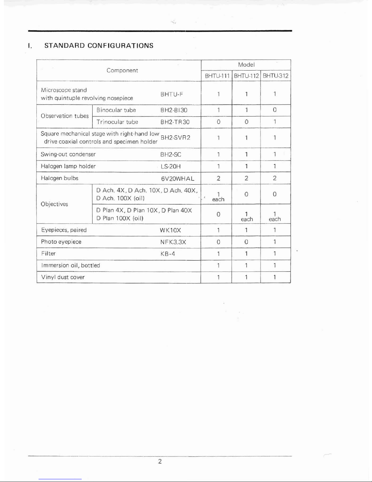
I.
STANDARD
CONFIGURATIONS
"",
Model
Component
BHTU·ll1
BHTU-112
BHTU·312
Microscope stand
BHTU·F 1 1
1
with
quintuple revolving nosepiece
8 inocular tube BH2·B130 1 1 0
Observation tubes
Trinocular tube
BH2·TR30 0 0
1
Square mechanical
stage
with
right-hand low BH2.SVR2
1 1
1
drive coaxial controls and specimen holder
Swing-out condenser
BH2·SC 1
1
1
Halogen lamp holder
LS·20H
1
1
1
Halogen bulbs
6V20WHAL
2
2 2
D Ach.
4X,
D Ach.
lOX,
D Ach,
40X,
1 0 0
D Ach. lOOX (oil)
each
Objectives
D
Plan
4X,
0 Plan
lOX,DPlan
40X
0
1 1
D
Plan
lOOX
(oil)
each each
Eyepieces, paired
WKlOX
1
1 1
Photo eyepiece
NFK3.3X 0 0
1
Filter
KB·4
1
1 1
Immersion oil, bottled
1
1
1
Vinyl
dust cover
1 1
1
2
II.
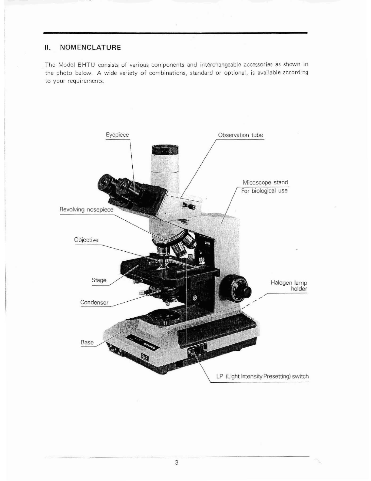
NOMENCLATURE
The Model
BHTU
consistsofvarious components and interchangeable accessoriesasshown in
the
photo
below. A wide varietyofcombinations,
standardoroptional,isavailable according
to
your
requirements.
Eyepiece
Objective
Stage
Condenser
-
3
Observation tube
Micoscope stand
For
biological use
Halogen lamp
holder
--
--
LP
(Light IntensityPresetting) switch
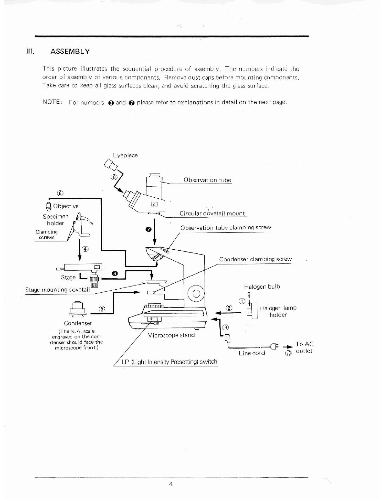
III.
ASSEMBLY
This picture illustrates the sequential procedureofassembly. The numbers Indicate the
orderofassemblyofvarious
components.
Remove
dust
caps
before
mounting
components.
Take care to keep all glass surfaces clean, and avoid :;cratching the glass surface.
NOTE:
For
numbers~andf)please refertoexplanations
in detail on the
next
page.
e ®
Condenser
(The
N.A.
scale
engravedonthe
con-
denser
shouldface
the
microscope
front.)
-..
To AC
® outlet
Halogen bulb
Q
CD,
~
Halogen lamp
9J holder
Condenser clamping screw
Observation tube
Observation tube clamping screw
Circular
dovetail
mount
Eyepjece
0)
.~
®
.g
Objective
Specimen
holder
Clamping
screws
~tage
L'
_I
.......;~;..-
Stage
mounting
dovetail
LP
(Light Intensity Presetting) switch
4
•
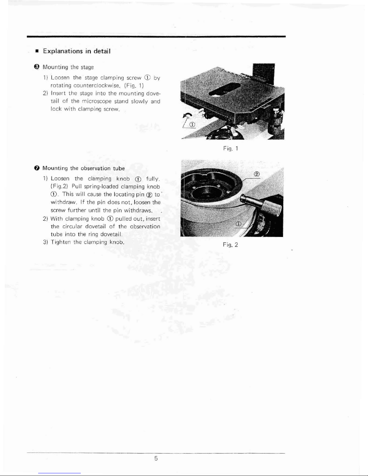
Explanations
in detaiI
9
Mountingthe
stage
11
Loosen the
stage
clamping screw
CD
by
rotating counterclockwise. (Fig. 1)
2) Insert the
stage
into the mounting dove-
tail
of
the microscope stand slowly and
lock
with
clamping screw.
fJ
Mounting the observation tube
1)
Loosen the clamping
knob
CD
fully.
(Fig.21 Pull spring-loaded clamping knob
CD.
This
will
cause
the locating pin<Vto·
withdraw.Ifthe pin does
not,
loosen the
screw
further until the pin withdraws.
2)
With
clamping knobCDpulled
out.
insert
the circular dovetail
of
the observation
tube into the
ring
dovetai
I.
3)
Tighten the clamping knob.
5
Fig.
Fig. 2
 Loading...