

Olympus BHTP 100, BHTP 200 Instruction Manual

OLYMPUS
~8TRumoH
POLAR12
lNG
I#ANua
OWMPIIS
MICROSCOPE
I
I
I
cm
rn
I
m-
1
This instruction
manual
has
been written
for
.the
use
of
the
Olympus
r(
Polarizing
Microscope Model
BHTF.
This
manual
should.
be
read.~afefully
so
that
the
wet
can
gain
familiarity with the
rni~mmpe
In
order
to
emure
1
optimum
performance,
i
I
IMPORTANT
Observe
the
following points carefully:
OPERATION
I.
Always handle the microscope
with
the
care
it
deserves,
and
avoid
abrupt
motions.
2.
Avoid
exposure
of
the
microscope
to
direct
sunlight,
high
tempera-
turn*
and
humidity,
dust
and
vibration.
*If
the
microswpe
is
used
in
ambient
temperature
higher
than
4O0C
(104T),
the heat
may
cause
difficulties in
the
instrument.
3.
Use
the
tansion
adjustment
ring
only
lor
altering
the
tensinn
of
the
coarse
adjustment.
Do
not
twist the
twocoarse
adlustment
knobs
in
the
opposite
directions
simultanmusly,
which
might
cause
damage.
4.
Ascertain
that
the
line
voltage
88Iector
switch
on
the
base
plate
is
set
to
conform
with
the local
mains
voltage.
MAINTENANCE
1,
Lenses
must
always
be
kept clean. Fine
dust
on
lens
surfaces
should
be
blown
or
wiped
off
by
means
of
an
air
blower
or
a
dean
brush.
Carefully
wipe
off
oil
or
fingerprints
deposited
on
the
lens
surfaces
with
gauze
moistened with
a
small amount of
xylene,
alcohol
or
ether.
1
2.
Do
not
use
organic
solutions
to wipe
the
surfaces
of
various components.
I
Plastic
parts,
especialiy,
shouid
be
cleaned
with a neutral
detergent.
<
3.
Hew
disassemble
the
microscope
for repair.
Only
authorized
Olyrn-
pus
service
petinel
should
make
repairs.
4.
The
microscope should
be
stored
in
its container immediately
after
-
use.
If
this
is not
possible,
it
should
be
covered with a vinyl dust
cover.
It
is
best to
keep
objectives
and
eyepieces
in
a
desiccator, containing
desicmmts.
I.
STANDARD
EQUIPMENT
2
II.
NOMENCIATURF
3
Ill.
ASSEMBLY
4
1V.
IDENTIFICATION
AND
FUNCTION
OF
VARIOUS
COMPONENTS
6
V.
OPERATION
10
A.
Switching
on
the
Light
!hum
10
8.
Adjusting
the
Observation
Tube
10
Ch
Use
of
the
Orientation
Plate
11
D.
Centering
the
bndenser
11
E.
Mering
the
Stage
12
E
Centering
the
Objectiws
13
G.
Use of
Iris Diaphragms
14
H.
Focus
Adjustment
14
I.
Use
of
Immersion
Objecti
1
5
J.
Orthcecoplc
Observation
15
K.
Conoscopic
Observation
16
~."~hotornicrography
I6
VI.
OPTICAL
DATA
17
V11. TROUBLESHOOTING
18
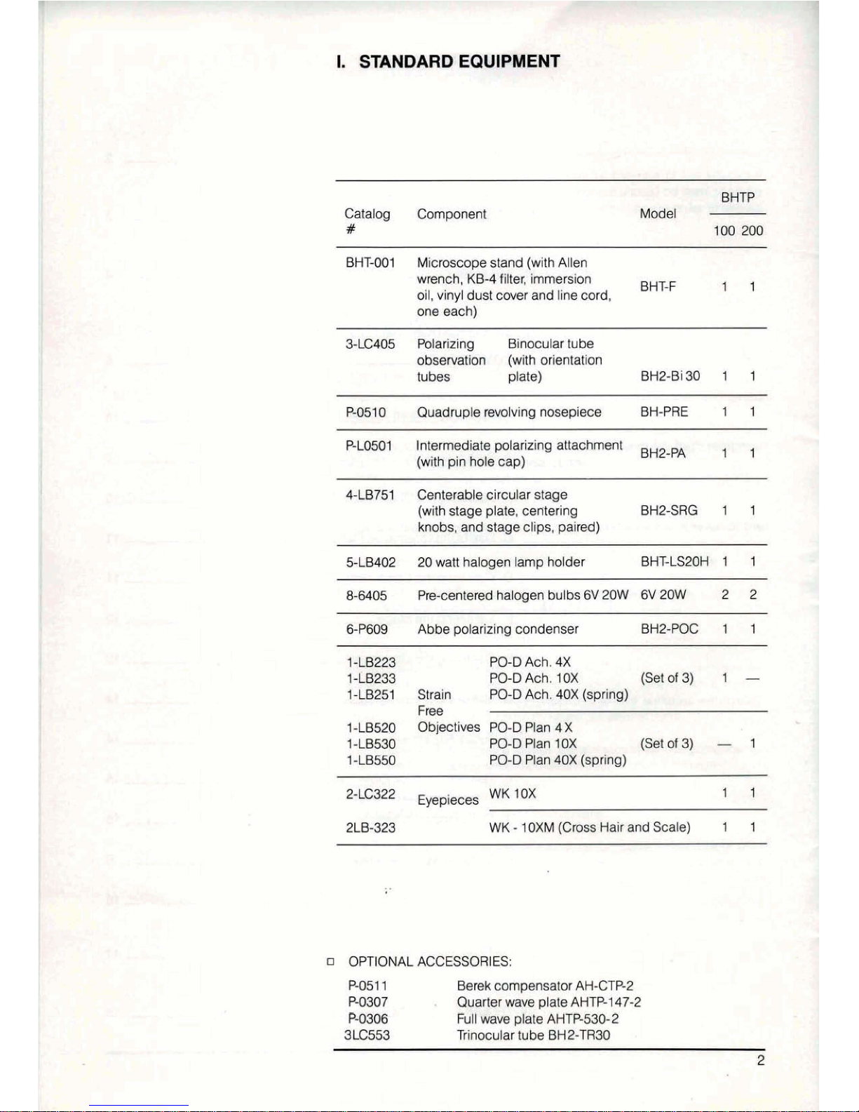
I.
STANDARD
EQUIPMENT
Catalog
Component
#
BM-001
Microscope
stand
(with
Allen
wrench,
KB4
filter,
tmmersion
oil,
vinyl
dust
cover
and line
cord,
BHT-F
1
I
one
each)
3-tC405
Polarizing
Binocular
tube
observation
(with
orientation
tubes
plate)
BH2-Bi30
1
1
PE10
Quadruple
revolving
nosepiece
BH-?RE
1
1
PL(WO1
Intermediate polarizing
attachment
BHBPA
,
,
(with
pin
hole
cap)
4LR751
Centerable
circu
tar
stage
(with
stage
plate,
centering
BHZ-SRG
1
1
knobs,
and
stage
dips,
paired)
5-W
20
watt
hatogen
lamp
holder
BHT-LS29H
1
1
8-8405
Pmcentered
haJogen
bulbs
6V
20W
f3V
20W
2 2
GP609
Abbe
polarizing
condenser
BH2-PaC
1
1
1
-m
PO-D
A&.
4x
1-LB233
PO-DA&.
IOX
(Scat
of
3)
1
-
1-16261
Strain
PO-D
Ach.
4OX
(spring)
Free
1-LBEQO
Objectives
W-0
Plan
4X
14653Q
W-0
Am
1OX
(atof3)
-
1
1
U550
PU-0
Plan
40X
(~pring)
BCC322
Eyepieces
WK
1OX
11
2LB-323
WK
-
10XM
(Cms
Hair
and
Scale)
1 1
a
OPTIONAL
ACCE5SOR~ES:
PO51
1
Berek
compensator
AH-CTP2
PO307
.
Quarter
wave
plate
AMP1
47-2
W66
kll
wve
plate
AHP-530-2
3LC553
Trinocular
tube
BH2-lR30
11.
NOMENCLATURE
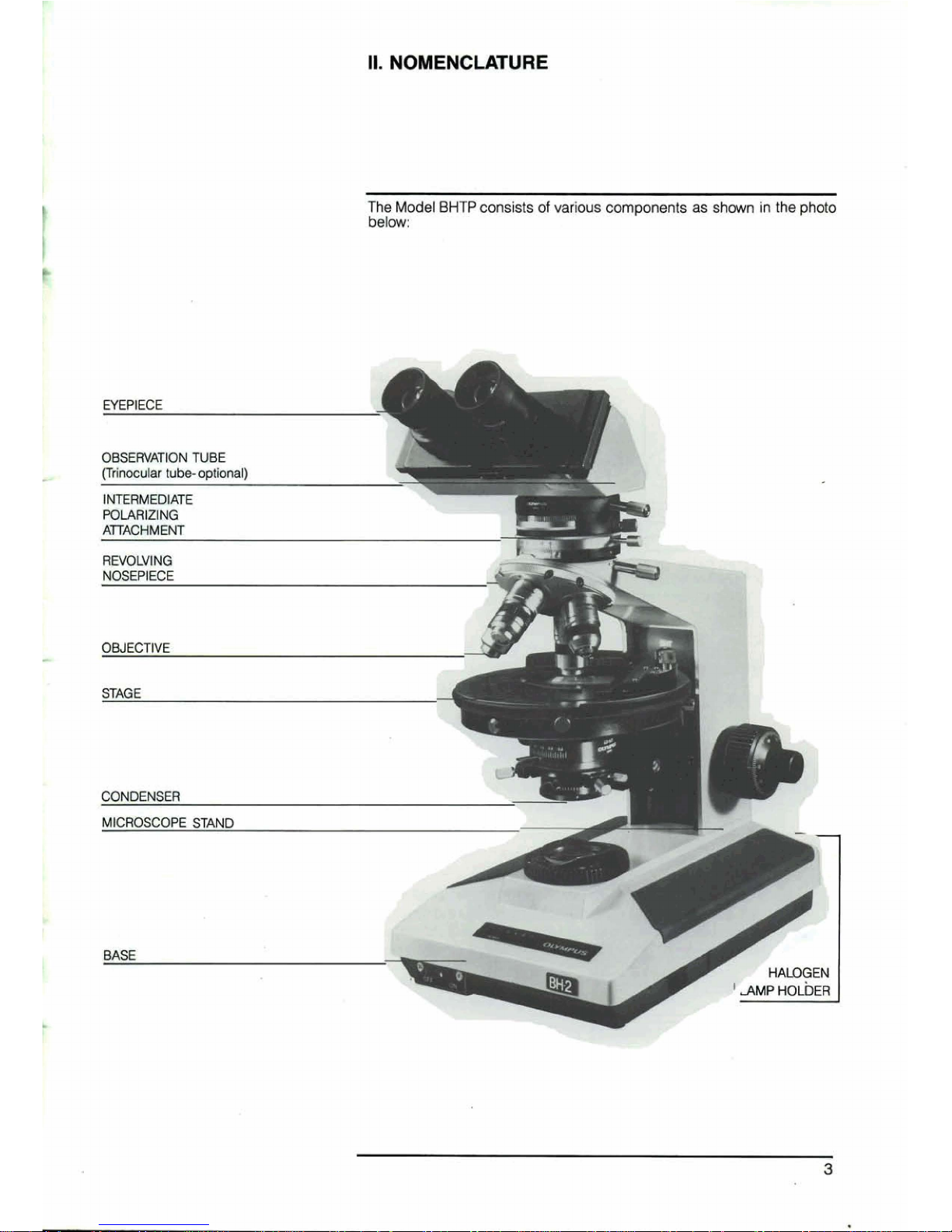
The
Model
BHTP
consists
of
various
components
as
shown
in
the
photo
blw:
STAGE
d
I.
m-
MICROSCOPE
STAND
Ill.
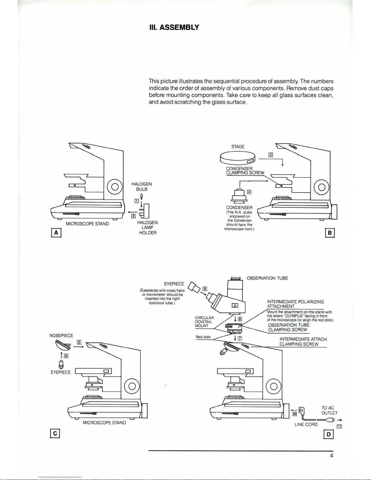
ASSEMBLY
This
picture
illustrates
the
sequential
procedure
of
assembly.
The
numbers
indicate
the
order
of
assembly
of
various
components.
Rwmwe
dust
caps
before
mounting components,
fake
care
to
keep
all
glass
surfaces
clean,
and
avoid
scratching
the
glass
surface.
HAG€
N
BULB
P
+!a
El
MICROSCOPE
STAND
WEN
tAMP
HOLOER
EYEPIECE
NOSEPIECE
-
MICROSCOPE
STAND
CONDENSER
CLAMPING
SCREW
I
CONDENSER
%2T
the
rrxld~m
-
OBSERVATION
TUBE
INERMEDIATE
POLMIZING
ClRCULM
OR€WAnQf4
TUBE
u-
UNE
CORD
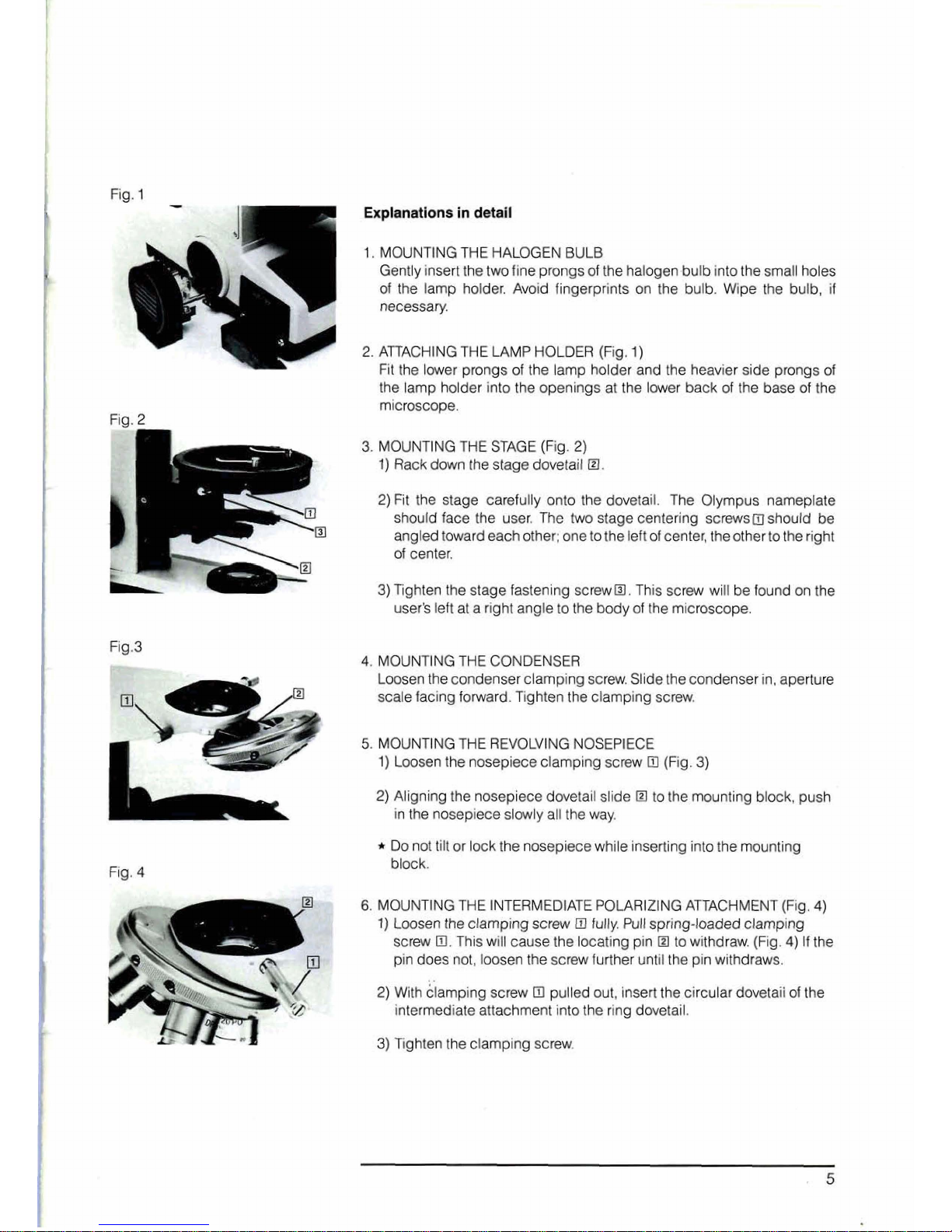
Fig.
1
-
--.
\q1
Explmatlons
In
detall
1.
MOUNTtMG THE
HALOGEN
BULB
r~
1
Gently
insert
the
two
fine prongs
of
the
halogen bulb
into
the small holes
of
the lamp holder. Avoid fingerprints on the bulb.
Wipe
the bulb,
if
necessary.
2.
AllACHING
THE
LAMP
HOLDER
(Fig.
1)
-
FI~
the
lower
prongs
of
the
lamp
holder
and
the heavier
side
prongs
of
the lamp holder into the openings at the lower back
of
the
base
of
the
microscope.
3.
MOUNTING
THE
STAGE
{Fig.
2)
1)
Rack
down
the
stage
dwetail
El,
2)
Fit the
stage
carefully onto the dovetail. The Olympus nameplate
should
face
the
user.
The
two
stage
centering
screws
should
be
angled toward
each
other;
one
to
the left
of
center, the other to
the
right
of
center,
3)
Tghten the stage
fastening
screw
@I.
This
screw
will be
found
on
the
user$
left
at
a
right
angle
to
the
body
of
the
microscope.
Rg.3
4.
MOUNTING
THE
CONDENSER
Loosen
the
condenser
clamping
screw.
Slide the
condenser
in,
aperture
scale
facing
forward.
Tighten
the
clamping
screw.
5.
MOUNTING
THE
REVOLVING
NOSEPIECE
1)
Loosen
the
nosepiece
clamping
screw
Dl
(Rg.
3)
Fig.
4
2)
Aligning
the
nosepiece
dovetail
slide
El
to
the mounting
block,
push
in
the
nosepiece
slowly
all
the
way.
Do
not
tilt
or
lock
the
nosepiece while inserting
into
the mounting
block.
6.
MOUNTING
THE
INTERMEDIATE POLARIZING
ATTACHMENT
(Fig.
4)
1)
Loosen
the
clamping
screw
El
fully.
Pull
spring-loaded clamping
screw
m.
This
will
cause
the locating pin
El
to withdraw.
(Fig.
4)
If the
pin
does
not,
loosen
the
s~rew
further
until
the
pin withdraws.
2)
Wfih
;lamping
screw
El
pulled
out,
insert
the
circular
dovetail
of
the
inlsrmediate attachment
into
the
ring
dwetait.
3)
Tghten
the
clamping
screw.
 Loading...