

Page 1

MiS
PLUS
Installation and Operations Guide
Guida
all'installazione e
all'uso
Fonctionnement
et
Installation
Bedienungs- und Installationshandbuch
Guia de instalacion y funcionamiento
Page 2

PUBLICATION ISSUED
BY:
Ing. C. Olivetti & C., S.p.A.
Direzione Documentazione
n, Via Jervis -
10015
Ivrea (Italy)
Copyright © 1988,
by
Olivetti
All
rights reserved
Ollvettl
ls a
trademark
ollng. C.
Olivetti
& C" S.p.A
em
Is a
trademark
01
Microsoft
Corp
.
MICROSOFT
IS
a
registered
Irademark
01
Mi
crosofl
Corp
.
MS IS
a
trademark
01
Microsoft
Corp
.
PUBBLICAZIONE EMESSA DA:
Ing. C. Olivetti & C
.,
S.p.A.
Direzione Documentazione
n, Via Jervis
10015
Ivrea (Italy)
Copyrig
ht
© 1988,
by
Olivetti
Tutti i diritti riservati
O
llve
lll e
un
marchio
della
Ing
. C.
Olivetti
& C
..
S.p.A.
GiN
•
un
marchio
della Microsoft
Corp
_
MICROSOFT e un
marchio
registrato
della
MicrosoU
Corp
.
MS t un
marchio
della
Microso
ft
Corp
.
EMISE DE:
Ing. C. Olivetti & C., S.p.A.
Direzione Documentazione
Via Jervis, n 10015 IVREA (Italie)
Copyrig
ht
© 1988, de Olivetti
Tous
droits reserves.
Ol
ivetti esl
uno
marque
commerciale
de
lng
. C.
Olivett
i & C
..
S.p.A
GW
ell
une marque
commerciale
de
Microsoft
Corp
.
MICROSOFT
est
une
marque
d~pos~e
de Microso
ft
Corp
.
MS
II I
une marque
commerciaJe
de
Microsoft
Corp
.
HERAUSGEGEBEN VON:
Ing.
C. Olivetti & C., S.p.A.
Direzione Documentazione
Via Jervis , n -
10015
IVREA (Italy)
Copyright © 1988,
by
Olivetti
Aile Rechte vorbehalten.
Olivetti
ist
eingetragenes
Warenzeichen
von
Ing
. C.
Olivetti
& C
.,
S.p.A
GW isl
eingelraQenes Warenzeichen
von
Microsofl Corp
.
MICROSOFT isl eingelfagenes
Warenzeichen
von
Microsoft
Corp
MS
isl
eingetragenes
Warenzeichen
von
Micro
soll
Corp
.
PUBLICACION EDITADA POR:
Ing.
C. Olivetti & C
.,
S.p.A.
Direzione Documentazione
n , Via Jervis -
10015
Ivrea (Italia)
Copyright ©
1988
,
by
Olivetti
Reservados todos los derechos
01illelli
es
una
marca
de
Ing
. C. Ol
iveni
& C
..
S.p.A
GW
es
una marca
de
Microsofl
Corp
.
MICROSOFT
es
una
marca
reglstrada
par
Microsolt
Corp
,
MS
es
una
marca
de
Microsoft
Corp
.
Information
from
Olivetti
Documentation
Informazione della
Documentazione
Olivetti
Informations
de
la
Documentation
Olivetti
Information
der
Olivetti-Dokumentation
Informaci6n
de
la
Documentaci6n
Olivetti
Page 3

NOTE, NOTA, REMARQUE, HINWEIS,
NOTA:
ENGLISH:
Systems with hard disk.
To
avoid any risk of damaging the hard disk, read carefully chapter 8,
before transporting your system.
ITALIANO:
Sistemi con hard disk.
Per
evitare eventuali danni all'hard disk, prima di spostare il vostro sistema,
leggete attentamente
il
Capitolo
8.
FRAN<;AIS:
Systeme a disque duro
Pour eviter
Ie
risque d'endommager
Ie
disque dur, lire attentivement
Ie
Chapitre 8 avant de transporter
Ie
systeme.
DEUTSCH:
Systeme mit Festplatte.
Um
jegliches Risiko einer Beschadigung der Festplatte auszuschlieBen,
lesen
die bitte aufmerksam
Kap
itel 8, bevor Sie Ihr System transportieren.
ESPANOL:
Sistemas con Disco Duro
Para evitar
eventuales darios
al
dis
co
duro, l
ea
atentamente
el
capi tulo
8, antes de desplazar su sistema.
Page 4

This
equipment conforms
to
the
specifications
of
the
EEC
directive
82/499
on
the
prevention
and
elimination
of
radio-frequency
disturbances.
Warning:
This
equipment
has
been
certified
to
comply
with
the
limits
for
a
Class
B computing
device,
pursuant
to
Subpart
J
of
Part
15
of
FCC
Rules.
Only
peripherals
(computer
input/
output
devices,
terminals,
printers,
etc.)
certified
to
comply
with
the
Class
B
limits
may
be
attached
to
this
computer.
Operation
with
non-
certified
peripherals
is
likely
to
result
in
interference
to
radio
and
TV
reception.
NOTICE
Ing.
C.
Olivetti
&
C.,
S.p.A.
reserves
the
right
to
make
any changes
in
the
product
described
in
this
manual
at
any
time
and
without
notice.
Page 5

PREFACE
This manual
is
provided
for
all
users
of
this
personal
computer.
It
contains
all
the
information
necessary
to
set
it
up
and begin
operation.
A
summary
of
the
guide
is
given
below.
CHAPTER 1 gives
a
general
description
of
the
possible
system
configurations,
the
starter
kit,
and informs about
software
requirements.
Chapter 2
helps
you
to
familiarize
yourself
with
the
system.
You
will
find
a
detailed
description
of
the
system
components,
controls,
indicators
and
interfaces.
Chapter J
describes
the
first
switching
on
of
the
system
and
the
autodiagnostics.
Chapter 4
gives
some
important
advice
on
the
care
and
handling
of
diskettes,
disk
drives
and
configurations
with
a hard
disk.
Chapter 5
explains
everything
necessary
to
load
an
operating
system, keyboard
drivers
and
the
travel
utility
for
configurations
with hard
disks.
Chapter 6
is
intended
to
familiarize
you
with
the
keyboard.
Chapter 7
gives
some
important
advice
on
working with
AC
power,
batteries
and
cable
connections.
Chapter 8
provides
all
the
information
needed
before
you
switch
OFr
your
PC
and
how
to
transport
it.
APPENDICES
A - 0
provide
the
following
information:
Page 6

A)
Adjusting
the
display
hinges,
upgrading
the
system
with an
optional
5.25"
disk
drive
and
replacing
the
batteries
and
the
backlight.
B)
Trouble
shooting,
Customer
Test
C)
Technical
characteristics
D)
List
of
figures
PRE-REQUISITE
PUBLICATIONS:
None
RELATED
PUBlICATIONS:
MS-DOS
User
Guide
DISTRIBUTION:
General
(G)
fIRST
EDITION:
March
1988
Page 7

CONTENTS
1.
INTRODUCTION
1-1
YOUR
PORTABLE
PERSONAL
COMPUTER
1-1
THE
TWO
POSSIBLE
CONFIGURATIONS
1-1
SUMMARY
OF
SYSTEM
FEATURES
1-3
IMPORTANT
SYSTEM
FEATURES:
BACKLIGHT,
BATTERY
1-3
HOW
TO
USE
THIS
MANUAL
1-4
THE
STARTER
KIT
1-5
CHECKING
YOUR
ORDER
1-5
SOFTWARE
REQUIREMENTS:
OPERATING
SYSTEM
2.
FAMILIARIZING
YOURSELF
WITH
THE
SYSTEM
2-1
CONNECTING
THE
STRAP
2-1
CHOOSING A WORKING
LOCATION
2-2
WORK
LOCATION,
SYSTEMS
WITH
HARD
DISK
2-3
OPENING
THE
COMPUTER
2-3
INSERTING
THE
TEMPLATE
FOR
THE
TWO
CONFIGURATIONS
2-4
REMOVING/REPLACING
THE
KEYBOARD
2-5
CONTROLS,
INDICATORS,
INTERFACES
2-5
System
and
display
v
Page 8

2-6
The
disk
drive(s)/hard
disk
2-7
Keyboard
2-8
Back
panel/interfaces
2-9
AC
adapter
3.
GETTING
STARTED
3-1
SELECTING
THE
TYPE
(BATTERY/AC)
Of
POWER
SUPPLY
3-2
BEfORE
SWITCHING
ON
-
USING
AN
AC
OUTLET,
CABLE
CONNECTIONS
3-2
BEfORE
SWITCHING
ON -AC
POWER -SYSTEMS
WITH
HARD
DISK
3-3
SWITCHING
ON -AC
POWER
3-3
WARNING -HARD
DISK
SWITCH
3-4
READJUSTING
THE
CONTRAST,
USING
THE
BACKLIGHT
3-4
THE
AUTODIAGNOSTICS
3-6
THE
AUTODIAGNOSTICS
(for
hard
disk
syste.s)
3-7
SWITCHING
ON -BATTERY
POWER -SYSTEMS
WITH
TWO
DISK
DRIVES
3-7
SWITCHING
ON -BATTERY
POWER -SYSTEMS
WITH
HARD
DISK
3-9
SWITCHING
Off -
SYSTEMS
WITH
TWO
DISK
DRIVES
3-9
SWITCHING
Off -
SYSTEMS
WITH
HARD
DISK
vi
M15
PLUS
INSTALLATION
AND
OPERATIONS
GUIDE
Page 9

CONTENTS
3-10
HARDWARE
RESET -SWITCHING
orf/ON
4.
DISKETTES,
DRIVES,
HARD
DISK
4-1
WORKING
WITH
DISKETTES
4-2
WRITE-PROTECTION
4-3
ATTACHING
LABELS
4-3
SOME
ADVICE
ON
THE
CARE
Of
DISKETTES
4-4
DISKETTE/HARD
DISK
ACCESS
INDICATOR
LIGHTS
4-4
Indicator
lights,
system with
two
disk
drives
4-4
Indicator
lights,
system with hard
disk
4-5
INSERTING
AND
REMOVING
THE
DISKETTES
4-5
Inserting
a
diskette
4-6
Removing
a
diskette
4-6
THE
HARD
DISK
4-6 Care and
handling
of
the
hard
disk
4-7
PROTECTING
THE
HARD
DISK
BEfORE
TRANSPORTING
THE
SYSTEM
5.
KEYBOARD
DRIVERS,
UTILITIES
5-1
LOADING
AN
OPERATING
SYSTEM
fROM A DISKETTE
IN
vii
Page 10

6.
DRIVE
A:
5-1
LOADING A NATIONAL
KEYBOARD
DRIVER
5-3
RECOMMENDED
STEPS
AfTER
LOADING
THE
OPERATING
SYSTEM
5-3 Copying
the
national
keyboard
driver
to
the
operating
system
diskette
5-3 Creating
an
AUTOEXEC.BAT
file
5-3 Creating a
CONFIG.SYS
file
on
your
operating
system
diskette
5-.
SYSTEM
WITH
HARD
DISK
5-.
COPYING
THE
TRAVEL
UTILITY
5-5 Using
the
travel
utility
WORKING
WITH
THE
KEYBOARD
6-1
ENTERING
TEXT
IN
UPPER
CASE
6-2
MULTI-CHARACTER
KEYS
6-3
THE
CURSOR
CONTROL
KEYS
6-3
THE
EDIT/SHIfT
KEY
6-.
THE
AUTOMATIC
REPEAT
fUNCTION
6-.
DEAD
KEY
SYMBOLS
6-6
THE
NUMBER
KEY
PAD
6-6
HOW
TO
COMPLETE
AN
ENTRY
v
iii
M15
PLUS
INSTALLATION
AND
OPERATIONS
GUIDE
Page 11
CONTENTS
6-7
CORRECTING
SPELLING
MISTAKES
WHEN
MAKING
ENTRIES
6-7
OTHER
SPECIAL
CHARACTERS
6-10
SWITCHING
BACK
TO
THE
US-ASCII
KEYBOARD
6-10
THE
SWISS-GERMAN/SWISS-fRENCH
KEYBOARD
6-10
THE
GREEK
KEYBOARD
6-11
THE
PORTUGUESE
KEYBOARD
6-11
SOfTWARE
RESET
(CTRL + ALT + DEL)
7.
AC/BATTERY
OPERATION,
CHARGING
THE
BATTERIES
7-1
GENERAL
7-1
BATTERY
BACK
UP
(IN
CASE
Of
POWER
fAILURE,
UNINTENDED
CABlE
DISCONNECTION)
7-2
DURATION
Of
OPERATION
ON
BATTERIES
UNDER
DIffERENT
CONDITIONS
7-2 Systems with
two
disk
drives
7-3 Systems with hard disk
7-4
WORKING
ON
BATTERIES;
BATTERY
LOW
INDICATOR
7-4
BATTERY
OPERATION,
CHARGING
UP
THE
BATTERIES
7-5
WORKING
ON
AC
AND
CHARGING
BATTERIES
7-6
IMPORTANT
fEATURE:
AUTOMATIC
CHARGING
Of
BATTERIES
WHEN
WORKING
ON
AC
ix
Page 12

7-6
NOTE
ON
fILE
SAVING
7-7
IMPORTANT
ADVICE
ON
WORKING
WITH
BATTERIES
7-7
CHARGING
UP
THE
BATTERIES
fOR
THE
fIRST
TIME
7-B
A
fEW
TIPS
ON
CABLE
CONNECTION/DISCONNECTION
7-8
SYSTEM
fEATURE:
ACOUSTIC
WARNING
IN
CASE
Of
NO
DRIVE/KEYBOARD
ACCESS
7-9
WHEN
IS
BATTERY
REPLACEMENT
NECESSARY?
8.
SWITCHING
Off,
TRANSPORTING
YOUR
SYSTEM
8-1
NOTE
ON
fILE
SAVING
8-1
SWITCHING
Off A
SYSTEM
WITH
TWO
DISK
DRIVES
8-1
PROTECTING
THE
HARD
DISK
BEfORE
SWITCHING
Off
A
SYSTEM
WITH
HARD
DISK
8-2
The
built-in
automatic
hard
disk
protection
utility
8-2
The
travel
utility
for
protecting
the
hard
disk
8-4
The
ship
disk
utility
in
the
Customer
Test
8-4
SPECIAL
SITUATIONS
8-4
TRANSPORTING
YOUR
SYSTEM
A.
ADJUSTMENTS,
UPGRADING,
REPLACING
BATTERIES
x
M15
PLUS
INSTALLATION
AND
OPERATIONS
GUIDE
Page 13
CONTENTS
A-I
SETTING/RE-ADJUSTING
THE
RESISTANCE
OF
THE
DISPLAY
HINGES
A-I
UPGRADING
THE
SYSTEM
WITH
THE
5.25"
OPTIONAL
DISK
DRIVE
A-2
REPLACING
THE
BATTERIES
A-3
REPLACING
THE
BACKLIGHT
B.
TROUBlE
SHOOTING,
CUSTOMER
TEST
B-1
TROUBLESHOOTING
B-3
THE
CUSTOMER
TEST
8-4
LOADING
AND
USING
THE
CUSTOMER
TEST
B-7
BEFORE
TRANSPORTING
THE
SYSTEM:
THE
PARK
DISK
HEADS
OPTION
8-8
HOW
TO
EXIT
THE
CUSTOMER
TEST
C.
TECHNICAL
CHARACTERISTICS
C-I
TECHNICAL
CHARACTERISTICS
D.
LIST
OF
FIGURES
xi
Page 14

INTRODUCTION
YOUR
PORTABLE
PERSONAL
COMPUTER
Thank
you
for
choosing
this
portable
Personal
Computer.
By
buying
this
particular
PC,
you
have
acquired
a
versatile
system, which, because
of
its
compatibility
with
Industry
Standards,
gives
you
access
to
a wide range
of
application
software.
The
system has an
incorporated
rechargeable
battery,
which
means
that
you
can
work
with
or
without
AC
supply,
as
you
wish. Because
of
its
compact measurements,
it
can
be
used
almost anywhere.
THE
TWO
POSSIBLE
CONfIGURATIONS
Two
system
configurations
are
available:
1.
SYSTEM
WITH
TWO
DISK
DRIVES
(each with a
capacity
of
720
KByte)
2.
SYSTEM
WITH
HARD
DISK
(20
MByte)
AND
ONE
DISK
DRIVE
(720 KByte)
SUMMARY
Of
SYSTEM
fEATURES
Below
is
a
brief
overview
of
the
technical
specifications
of
the
system:
Internal
storage
capacity:
S12K
bytes
Intel
BOCBB
Processor
(16
bit
internal
bus)
Mass
storage,
external
storage
capacity:
configuration
1:
2
integrated
disk
drives,
each one with
720K
bytes
capacity,
using
3.5"
microdiskettes
1-1
Page 15

1-2
configuration
2:
1.
1
integrated
hard
disk,
storage
capacity
20
MBytes
2. 1
integrated
disk
drive,
720
Kbytes
capacity
Interface
for
connecting
an
optional
5.25"
disk
drive.
This can be used
to
read/write
software
directly
from/to
5.25"
diskettes
(capacity
360K
bytes).
Liquid
crystal
display
with:
1.
backlight
2.
contrast
control
3.
25
lines
of
80
characters
per
line
in
text
mode
(or
25
lines
of
40
characters
per
line)
4.
Graphics
capability,
with a resolution
of
640 x 200
pixels.
The
keyboard has
78
keys,
and can be
left
in
the
system
or
taken
out
and
moved
to
any
position.
Any
of
a range
of
national
keyboard
versions
can be
supplied.
A wide
variety
of
printers
can be
connected
to
the
system,
to
meet
diverse
needs.
The
system can be equipped
with
an
adjustable
shoulder
strap.
A
carrier
bag
is
supplied
for
transporting
the
system,
along
with
its
accessories.
M15
PLUS
INSTALLATION
AND
OPERATIONS
GUIDE
Page 16

IMPORTANT
SYSTEM
fEATURES:
BACKLIGHT,
BATTERY
INTRODUCTION
The
display
of
your system
is
equipped
with
a
backlight
which
allows
you
to
use your
PC
in
different
lighting
conditions.
Thanks
to
the
built-in
rechargeable
batteries,
you can use
this
system even where
there
is
no
AC
outlet.
HOW
TO
USE
THIS
MANUAL
At
the
end
of
this
manual you
will
find
a
fold-out
appendix,
which
contains:
all
the
illustrations
referred
to
in
the
text,
in
the
order
they
are
referred
to,
showing
all
the
important
operations
which
may
be
carried
out
on
the
computer.
illustrations
of
all
the
available
national
keyboard
versions.
Please
unfold
this
appendix and
turn
to
the
illustration
(1)
•
When
reference
is
made
in
the
manual
to
certain
components,
for
example
(4)
or
(3,8)
etc.,
the
components
will
be found
by
these
numbers
in
the
illustrations
of
the
appendix.
For
example
the
number
(4)
refers
to
Figure
4;
the
number
(3,8)
refers
to
the
component marked B
in
Figure
3.
In
this
way, you can
follow
the
text
and have
the
corresponding
illustrations
available
at
a
glance.
1-3
Page 17

THE
STARTER
KIT
The
Starter
Kit
has been
designed
to
supply
everything
necessary
to
start
up
and begin working
with
the
system.
The
Kit,
which has been
supplied
with
your system,
consists
of
the
following:
This manual
1
Diskette
(3.5")
labeled:
UTILITIES
2
templates
to
be
inserted
in
the
area
above
the
keyboard. These
templates
can
be
used
to
describe
your
function
keys. In
addition
they
help
you
to
identify
your
disk
drives
(and/or
your hard
disk).
On
the
diskette
marked
UTILITIES
you
will
find
the
national
keyboard
drivers,
which must be loaded
when
you
have a
keyboard
version
other
than
the
US
ASCII
keyboard. In
addition,
you
will
find
the
Customer
Test
software
and
the
Travel
utility
on
this
diskette.
The
Customer
Test
software
can be used
to
test
the
hardware
of
your
system.
The
Travel
utility
is
needed
when
you
have a system
with
hard
disk.
The
Travel
utility
offers
a
way
(among
others)
to
park
the
heads
of
the
hard
disk
in
a
safe
position.
This
utility
can be used
before
a system
with
hard
disk
is
transported.
M15
PLUS
INSTALLATION
AND
OPERATIONS
GUIDE
Page 18

INTRODUCTION
CHECKING
YOUR
ORDER
Please
make
a
brief
check
of
the
items
in
the
package:
the
portable
PC
(l,A),
comprising
display,
keyboard,
and
two
integrated
disk
drives
or
(hard
disk
configurations)
one
integrated
hard
disk
and an
integrated
disk
drive.
1
carrier
case
(I,B)
1
shoulder
strap
(I,H)
Starter
Kit
(1,0)
with
manual and
UTILITIES
diskette
2
templates
(I,e)
(to
be
inserted
in
the
area
above
the
keyboard)
AC
adapter
with
DC
cable
(I,G)
(I,f)
1
AC
power
cable,
for
AC
adapter-AC
outlet
connection
(I,E)
We
recommend
that
you
keep
all
the
packing
material,
as
it
will
be
useful
for
reshipment.
SOfTWARE
REQUIREMENTS:
OPERATING
SYSTEM
You
will
not
be
able
to
fully
utilize
your
Personal
Computer
until
an
operating
system
(or
appropriate
application
program)
is
loaded
into
its
memory.
This
is
NOT
INCLUDED
in
the
Starter
Kit
which
comes
in
the
box
with
this
computer.
You
can
purchase
the
operating
system from
your
dealer.
The
operating
system
to
be
used
on
this
system
is:
3.2
MS-DOS
1-5
Page 19

fAMILIARIZING
YOURSElf
WITH
THE
SYSTEM
CONNECTING
THE
STRAP
The
shoulder
strap
(I,H),
provided
in
the
box,
will
help
you
when
transporting
your system.
To
connect
the
carrying
strap
proceed
as
follows
(2):
1.
Put one end
of
the
carrying
strap
around
the
metal
holder
(2,C)
on
the
left
side
of
the
system,
and
put
the
metal
pin
(2,0)
into
the
hole
on
the
end
of
the
strap.
2. Put
the
other
end
of
the
carrying
strap
around
the
metal
holder
(2,A)
on
the
right
side
of
the
system and
put
the
metal
pin
(2,8)
into
the
hole
on
this
end
of
the
strap.
3.
By
moving
the
clasp
(2,r)
to
the
left
or
right
you
can
adjust
the
length
of
the
belt
as
you
wish.
CHOOSING A WORKING
LOCATION
This computer system
is
designed
to
be
portable;
that
is,
you
can use
it
safely
in
different
types
of
location
and
in
varying
working
environments.
If
you
intend
to
use
the
computer
in
a
non-office
environment, and
in
unusual
or
rough
conditions,
please
pay
attention
to
the
following
points:
Avoid:
1.
using
the
system
in
a chemical
or
environment
dust-laden
2. exposing
the
equipment
to
extremes
of
temperature
or
humidity
3. knocks and
vibrations
4.
placing
the
equipment
near
sources
of
electrical
or
magnetic
interference,
such
as
large
transformers,
2-1
Page 20

high-frequency
devices,
large
electric
motors,
or
telephones.
You
should
also
take
care:
not
to
expose
the
system
to
direct
sunlight.
when
operating
from
the
AC
outlet,
to
check
that
there
is
a ground
(earth)
connection.
For
the
technical
characteristics
of
unusual
conditions,
with
respect
humidity,
see
the
chapter
on
Technical
the
end
of
the
manual.
WORK
LOCATION,
SYSTEMS
WITH
HARD
DISK
the
equipment under
to
temperature
and
Characteristics
at
Note
the
following
if
you
have a system with hard
disk:
When
you
are
using
a system with hard
disk
and
the
hard
disk
is
switched
ON
the
system should
not
be
moved
more
than
necessary.
The
system should
not
be
exposed
to
any
knocks,
vibrations
etc.
You
can
also
use a system with hard
disk
with
the
hard
disk
switched
OFF.
(Hard
disk
switch
(15,E)
in
position
OFF
(=0),
battery
operation;
hard
disk
heads parked
in
a
safe
position
as
described
in
this
aanual).
In
this
case
you
don't
have
to
take
the
above
precautions.
2-2
"15
PLUS
INSTALLATION
AND
OPERATIONS
GUIDE
Page 21

fAMILIARIZING
YOURSELf
WITH
THE
SYSTEM
OPENING
THE
COMPUTER
1.
The
flip-up
display,
when
closed,
is
held
in
place
by
two
plastic
clips,
(J,A)
, one
on
each
side
of
the
lid.
To
open,
press
both
these
clips
simultaneously
at
the
bottom and
li
ft
the
display
(J,B)
upward.
2.
Set
the
display,
to
the
desired
angle
for
optimum
viewing.
I~rtant:
The
display
lid
can be
set
in
up
to
the
maximum
angle
of
inclination.
the
following
points
when
opening:
many
positions,
Pay
attention
to
1.
Always open
the
lid
carefully:
never
try
to
force
it.
(The
resistance
can be
readjusted
according
to
the
description
in
Appendix A).
2.
You
will
find
the
point
of
most
resistance
when
you
have
reached
the
maximum
angle
of
opening.
3.
When
closing
the
display,
let
it
down
softly
with
your
hands;
do
not
let
it
fall
back
into
place.
Above
all,
do not slam
it.
Fig.
(4)
shows a system
with
two
disk
drives
(4,A,B).
Fig.
(5)
shows a system
with
hard
disk,
(5,A)
disk
drive
A:,
(5,C)
hard
disk
(drive
C:).
INSERTING
THE
TEMPLATE
fOR
THE
TWO
CONfIGURATIONS
In your
starter
kit
there
are
2
templates
to
be
inserted
in
the
area
above
the
keyboard. These
templates
can
be
used
to
describe
your
function
keys.
In
addition
they
help
you
to
identify
your
disk
drives
(and/or
your hard
disk).
The
templates
are
printed
on
both
sides
(one
side
to
be
used
for
systems
with
two
disk
drives,
one
side
to
be used
2-J
Page 22

for
systems
with
hard
disk).
If
you
have a system
transparent
plastic
insert
the
template
plastic
sheet.
with
sheet
(I,C)
two
disk
drives:
Take
the
from above
the
keyboard
(4,0),
and
reinsert
the
transparent
Note
the
symbols
for
the
disk
drives:
(6,A,B).
If
you
have a system
with
hard
disk
(7),
note
the
symbols
for
hard
disk
and
the
disk
drive:
(7,C,A).
REMOVING/REPLACING
THE
KEYBOARD
There
are
two
different
ways
of
positioning
the
keyboard:
a)
It
is
designed
in
such a
way
that
you
can
quite
easily
leave
it
and use
it
in
the
transport
position
(4),(5)
.
b)
You
can
take
the
keyboard
out
and
place
it
anywhere
you
wish.
When
you
wish
to
do
this,
please
proceed
as
follows:
2-4
1.
Lift
up
the
keyboard
using
the
thumbgrooves (8,A)
provided
on
the
front:
first
press
it
lightly
as
indicated
by
arrow
(8,B)
and
then
lift
it
out
as
indicated
by
arrow
(8,C).
Take
it
out
of
the
housing
(9).
2.
Pullout
the
keyboard
cable
which
you
will
find
wound
around
the
two
plastic
pins
(10,B,C)
3.
Place
the
keyboard wherever
you
wish.
4.
Check
that
the
keyboard
connector
(10,A)
is
set
straight
in
its
socket.
Apply
slight
pressure
to
ensure
that
the
connector
is
fully
inserted.
When
you
wish
to
disconnect
the
keyboard,
pull
the
plastic
connector
(10,A)
out
of
the
socket.
To
H15
PLUS
INSTALLATION
AND
OPERATIONS
GUIDE
Page 23

fAMILIARIZING
YOURSELf
WITH
THE
SYSTEM
re-insert
the
connector,
push
it
fully
into
the
socket.
5.
When
replacing
the
keyboard
in
its
housing,
be
careful
to
wind
the
cable
around
the
plastic
pins
(10,8,e).
Make
sure
that
the
left
and
right
corner
of
the
keyboard
are
positioned
under
the
plastic
edges
as
indicated
by
(ll,D).
Then
press
the
keyboard
slightly
as
indicated
by
the
arrows
(11,8)
and
(ll,e).
When
the
keyboard
is
back
in
its
original
position,
it
should
be
evenly
aligned
with
the
sides
of
the
housing.
6.
Before
closing
the
display
lid,
ensure
that
the
keyboard
is
correctly
in
position.
CONTROLS,
INDICATORS,
INTERfACES
Before you
begin
working,
make
a
brief
visual
check
of
the
system,
the
rear
panel,
and
the
power
supply
unit.
You
will
see
the
following
controls
and
indicators:
Syste.
and
display
ON/OFF
switch
(12,A)
o
position
= System
OFF
1
position
= System
ON
Speaker (13,A)
Power
indicator
light
(green)
(13,e)
This
indicator
lights
up
when
the
system has been
switched
on.
Battery
indicator
light
(green)
(13,8)
2-5
Page 24

This
indicator
lights
up
when
the
battery
needs
to
be
recharged.
Display
contrast
control
knob
(13,0)
This
is
used
to
adjust
the
contrast
setting
on
the
display.
Turn
clockwise
to
increase
the
contrast.
The
screen
will
become
generally
darker.
Volume
control
knob
(13,E)
This
controls
the
volume
of
the
sound
on
the
speaker.
Turn
clockwise
to
increase
the
volume.
BACKLIGHT
ON/OFF
switch
(13,r)
This
switches
the
built-in
backlight
ON
or
OFF.
(ON
=
backlight
at
maximum
brightness)
(OFF = backlight
at
minimum
brightness)
The
disk
drive(s)/hard
disk
SYSTEMS
WITH
TWO
DISK
DRIVES:
Disk
drive
A
(right
hand
side)
(12,0)
Disk
drive
B
Cleft
hand
side)
(12,r)
Disk
drive
indicator
light
(drive
A)
(12,C)
Disk
drive
indicator
light
(drive
B)
(12,
B)
These
indicators
come
on
when
the
system
is
accessing
the
disk
drive(s).
On
each
disk
drive
note:
A
disk
drive
cover
(12,r)
2-6
M15
PLUS
INSTALLATION
AND
OPERATIONS
GUIDE
Page 25

fAMILIARIZING
YOURSELf
WITH
THE
SYSTEM
A
disk
drive
release
button
(12,E)
When
pressed,
this
button
partially
ejects
any
microdiskette
present
in
the
disk
drive.
SYSTEMS
WITH
HARD
DISK:
Disk
drive
A
(right
hand
side)
(12,0)
HARD
DISK
C (12,H)
(left
hand
side)
Hard
disk
drive
cover
(12,H).
This
protects
the
hard
disk.
It
should
not
be
removed.
Disk
drive
indicator
light
(drive
A)
(12,C)
Hard
disk
indicator
light
(drive
C)
(12,8)
These
indicators
come
on
when
the
system
is
accessing
the
disk
drive/hard
disk.
Keyboard
78
keys,
including:
a)
10
Function Keys,
Fl
to
FlO
(14,A)
b)
integrated
numeric keypad
(14,8)
c)
cursor
control
keys
(14,0)
Indicator
light
on
the
NUM
LOCK
key (14,C)
When
this
key
is
pressed,
the
indicator
light
shows
that
the
number keys
are
activated.
Indicator
light
on
the
CAPS
LOCK
key
(14,E)
When
the
CAPS
LOCK
key
is
pressed,
this
indicator
light
shows
the
alphabetic
section
of
the
keyboard
is
in
2-7
Page 26
upper
case
mode.
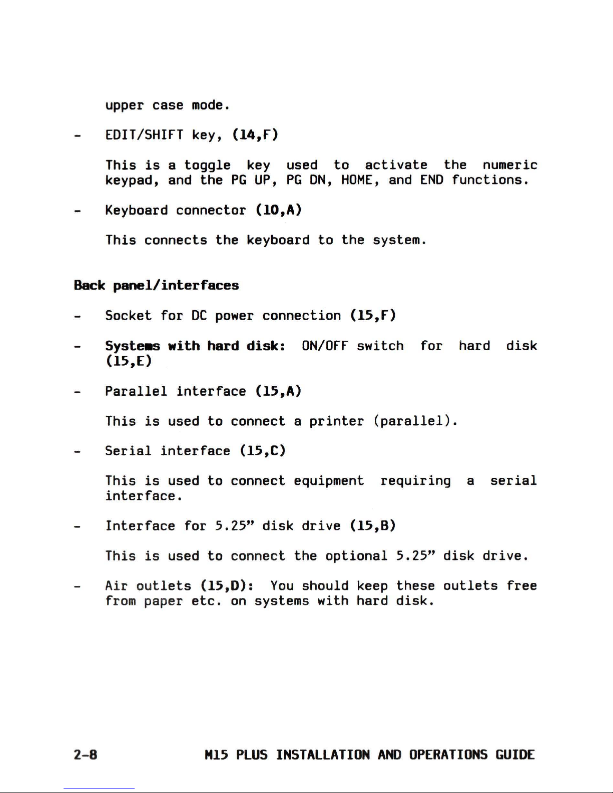
EDIT/SHIFT
key,
(14,f)
This
is
a
toggle
key used
to
activate
the
numeric
keypad, and
the
PG
UP,
PG
ON,
HOME,
and
END
functions.
Keyboard
connector
(IO,A)
This
connects
the
keyboard
to
the
system.
Back
panel/interfaces
2-8
Socket
for
DC
power
connection
(15,f)
Systeas
with
hard
disk:
ON/OFF
switch
for
hard
disk
(15,E)
Parallel
interface
(15,A)
This
is
used
to
connect
a
printer
(parallel).
Serial
interface
(15,e)
This
is
used
to
connect
equipment
requiring
a
serial
interface.
Interface
for
5.25"
disk
drive
(15,8)
This
is
used
to
connect
the
optional
5.25"
disk
drive.
Air
outlets
(15,D):
You
should
keep
these
outlets
free
from
paper
etc.
on
systems
with
hard
disk.
MI5
PLUS
INSTALLATION
AND
OPERATIONS
GUIDE
Page 27

FAMILIARIZING
YOURSELF
WITH
THE
SYSTEM
AC
adapter
The
universal
AC
adapter
(16,0)
can
be
connected
to
AC
voltages
from 100
volt
to
240 Volt
(AC
frequency:
50
Hz,
and 60 Hz).
(AC
input
socket
(16,E)
)
DC
power
supply
cable
(16,C)
for
connecting
the
AC
adapter
to
the
computer,
when
operating
from an
AC
outlet
and
when
charging
the
batteries.
Power
supply
indicator
light
(green)
(16,A)
lights
up
when
the
AC
adapter
is
connected
to
a
wall
outlet.
IMPORTANT
NOTE:
SWITCHING
ON-Off;
TRANSPORTING A SYSTEM
WITH
HARD
DISK
If
you
switch
ON/OFF
a system
with
hard
disk,
please
refer
to
Chapter
8,
which
explains
all
steps
to
be performed
to
protect
the
hard
disk
before
you
transport
the
system.
2-9
Page 28

GETTING
STARTED
SELECTING
THE
TYPE
Of
POWER
SUPPLY
(BATTERY/AC)
Each time
you
are
about
to
switch
on
the
system,
consider
which
type
of
power
supply
you
wish
to
use:
a)
AC
(through
the
AC
adapter);
the
batteries
will
automatically
be
charged
if
they
have
reached a certain
level
of
discharge
b)
battery
supply
Your
decision
should
be based
on
the
following
points:
a)
AC
supply:
connect
the
system
to
an
AC
outlet
whenever
there
is
one
available.
AC
supply
with
simultaneous
charging
of
the
batteries:
if,
when
operating
on
batteries,
the
indicator
light
beside
the
display
shows
that
the
batteries
have
become
discharged,
connect
the
system
as
soon
as
possible
to
an
AC
outlet
through
the
AC
adapter,
powering
the
system and
recharging
the
batteries
at
the
same
time.
b)
Battery
supply:
if
you
are
travelling,
or
you
find
yourself
in
places
where
there
is
no
AC
outlet,
you
can
run your system
independently
on
the
rechargeable
batteries.
Battery
operation
entails
certain
time
limits,
and
it
is
therefore
advisable
to
plan
your use
of
the
system
in
advance
when
you
intend
to
run
it
on
batteries
(this
is
explained
in
detail
in
Chapter
7).
Each time
you
switch
off
after
using
the
batteries,
you
should
consider
whether
they
need
to
be
recharged.
3-1
Page 29

BEFORE
SWITCHING
ON -USING
AN
AC
OUTLET,
CABLE
CONNECTIONS
The
first
time
you
switch
on
we
recommend
the
use
of
an
AC
power
supply.
When
doing
so,
it
is
essential
to
proceed
as
follows:
1.
Check
that
the
ON/OFF
switch
(17)
is
in
the
0
Position
(=
OFF),
before
making
or
changing any
of
the
cable
connections.
2. Ensure
that
the
voltage
and frequency
values
available
from
the
AC
outlet
are
in
the
range
indicated
on
the
AC
adapter
(100 - 240
V,
50
Hz,
60
Hz).
3.
Insert
the
DC
cable
jack
(18,A)
of
the
AC
power
supply
in
the
DC
socket
on
the
rear
of
the
computer.
4.
Plug
in
the
AC
supply
cable
(19,A)
into
the
AC
adapter.
5.
IMPORTANT:
The
last
step,
when
connecting
the
system
through
the
AC
adapter
to
the
AC
outlet,
should
always
be
the
connection
of
the
AC
cable
to
the
AC
outlet
(20,A)
,even
when
you
intend
to
charge
the
batteries.
The
green
indicator
light
on
the
AC
adapter
(16,A)
lights
up
when
the
adapter
is
connected
to
a
wall
outlet.
BEFORE
SWITCHING
ON -AC
POWER -SYSTEMS
WITH
HARD
DISK
Whenever you
operate
a system
with
hard
disk
on
AC
power
the
hard
disk
will
be
switched
on
automatically
and
recognized
by
the
system
as
soon
as
the
power
switch
(22,A)
is
switched
ON.
This
is
independent
of
the
position
(0/1)
of
the
hard
disk
switch
(18,8).
A
small
note:
your system
is
equipped
with
a backup
facility.
That means
that
if
there
is
an
AC
power
failure
3-2
M15
PLUS
INSTALLATION
AND
OPERATIONS
GUIDE
Page 30
GETTING
STARTED
or
an
unintended
cable
disconnection
the
system
will
automatically
be powered
by
the
batteries.
No
data
will
be
lost.
In
such a
case
the
hard
disk
will
battery
power)
only
if
the
hard
position
ON
(=1).
continue
working (on
disk
switch
is
in
the
When
you
work
in
environments where
the
AC
power
is
not
very
reliable,
we
recommend
as
a
matter
of
routine,
that
you
leave
the
hard
disk
switch
in
position
ON
(=1)
if
the
hard
disk
is
needed
while
you
are
working.
SWITCHING
ON -AC
POWER
1.
Turn
the
contrast
control
knob (21,A)
to
the
maximum
brightness
position
(anti-clockwise).
Maximum
brightness
means
minimum
contrast.
2.
Switch
the
backlight
switch
(21,8)
into
the
OFF
position.
3.
Switch
the
system
on
(setting
the
ON/OFF
switch
(22,A)
to
position
ON
(=1).
The
power
indicator
light
(2J,A)
(green
comes on.
WARNING -HARD
DISK
SWITCH
power
ON)
I~ortant:
After
you
switched
ON
a system
with
hard
disk,
don't
change
the
position
of
the
hard
disk
switch
(18,8).
The
results
may
be
unpredictable.
Before changing
the
position
of
the
hard
disk
switch,
save
your
current
work
session
and
switch
the
system
OFF.
J-J
Page 31

READJUSTING
THE
CONTRAST,
USING
THE
BACKLIGHT
Turn
the
contrast
control
knob
(23,8)
slowly
clockwise
so
that
the
information
appearing
on
the
screen
can be
read
clearly.
In
the
maximum
and
mlnlmum
positions
(maximum/minimum
contrast)
nothing
can be
distinguished
on
the
screen.
At
this
point
we
recommend you
switch
ON
the
backlight
and
readjust
the
contrast.
Depending
on
the
lighting
conditions
at
your work
location
you
will
find
a
significant
improvement
in
readability/clarity
when
text/graphic
is
displayed
on
your
system.
Switch
the
backlight
OFF
and
ON
and
observe
the
difference.
Since
you
will
be
using
your system
in
many
different
environments
adjust
the
display
angle,
the
contrast
knob
and
the
backlight
for
optimum
readability
on your
display.
THE
AUTOOIAGNOSTICS
When
the
system
is
switched
on,
an
automatic
is
run,
which
is
called
the
autodiagnostic.
tests
the
main hardware components
of
the
displays
the
results.
test
program
This
program
system and
)- 4
The
first
time
you
turned
your
system
on,
because
of
the
adjustments
you have been making
to
the
contrast
and
to
the
backlight,
it
is
possible
that
you
could
not
see
some
of
the
information
displayed;
we
therefore
recommend,
at
this
point,
that
you
switch
the
system
off,
wait
for
several
moments, and
then
switch
on
again
(HARDWARE
RESET).
(Obviously,
this
operation
of
switching
the
system
off
and
then
on
again
is
not
necessary
when
the
contrast
control
knob
is
left
in
the
normal working
position.)
M15
PLUS
INSTALLATION
AND
OPERATIONS
GUIDE
Page 32

GETTING
STARTED
You
can
follow
the
diagnostic
messages
as
they
appear
.
On
the
left
is
shown
the
component
reference
(24),
for
example:
CPU
(80C88)
PASS
The
word
PASS
appearing
to
the
right
of
the
component
reference
means
that
the
test
has
been
successful.
The
word
FAIL
appearing
to
the
right
of
the
component
reference
means
that
the
component
has
failed
the
test.
The
abbreviations
used
are
in
English
(e.g.
CPU
=
Central
Processing
Unit).
Note: A
fail
message does
not
necessarily
mean
that
the
system
cannot
be
used.
Some
errors
are
transient.
In
case
of
a
fail
message
we
recommend you
perform
a
Hardware
Reset
(switch
the
system
OFF
and
ON
again).
If
the
fail
message
continues
to
appear
run
the
Customer
Test
(explained
in
Appendix B).
On
conclusion
of
the
diagnostics
(which
last
some
seconds)
the
LED
indicator
light
(6,A),(7,A)
for
the
right
hand
disk
drive
(12,0)
(under
the
LCD)
comes on.
This
indicates
that
the
system
is
looking
for
a
diskette
in
the
disk
drive.
While
it
is
doing
so,
the
green
indicator
light
remains
lit.
( Never
try
to
insert
a
diskette
in,
or
remove one from, a
disk
drive
while
the
green
light
is
on.)
This
will
last
some
seconds,
and
then
the
following
message
will
appear:
Insert
syste.
disk
for
drive
A:
and
strike
any key
when
ready.
This
message means
that
the
system
is
now
awaiting
an
operating
system
diskette
(or
a
diskette
with
the
operating
system
and
application
software)
in
disk
drive
A
(the
right-hand
disk
drive).
3-5
Page 33

As
mentioned
previously,
the
operating
system
diskette
is
ordered
and
delivered
separately.
When
you
come
to
insert
this
diskette,
please
read
the
following
Chapter
on
the
handling
of
diskettes
before
doing
so.
THE
AUTODIAGNOSTICS
(for
hard
disk
systems)
When
you have a system
with
hard
disk
you
will
have
to
distinguish
between
different
situations:
In
the
situations
described
below
the
autodiagnostic
shows
the
additional
message:
HDU
ready
(25,A).
This
means
that
the
system
has
recognized
your
hard
disk,
and
it
is
now
available
for
operations:
You
are
operating
on
AC
power. Hard
disk
switch
is
in
either
position.
You
are
working
on
batteries.
The
hard
disk
switch
is
in
the
ON
position.
Note:
this
switch
(18,8)
must be
switched
on
before
the
power
switch
(17,A)
has
been
switched
on.
In
the
situations
described
below
autodiagnostic
shows
the
additional
message:
HDU
is
not
available
(26).
You
hear
two beeps and
the
message
will
be
blinking
for
a
few
seconds
.
This
message means
that
the
system
did
not
recognize
the
hard
disk.
Every
access
to
the
hard
disk
will
fail
(an
appropriate
error
message
is
displayed).
3-6
You
are
working
on
batteries.
The
switched
on. Hard
disk
switch
position
(=0).
hard
disk
(18,8)
in
is
not
the
OFF
H15
PLUS
INSTALLATION
AND
OPERATIONS
GUIDE
Page 34

GETTING
STARTED
You
are
working
on
batteries.
The
hard
disk
is
switched
on. Hard
disk
switch
(18,8)
in
the
ON
position
(=1);
however,
you
switched
the
hard
disk
on
after
the
power
switch
(22,A) has been
switched
on.
We
recommend
as
a
matter
of
routine
that
you
follow
the
autodiagnostics
(message:
HDU
ready)
when
you
are
planning
to
use your
hard
disk
to
make
sure
that
the
hard
disk
is
available.
SWITCHING
ON -BATTERY
POWER -SYSTEMS
WITH
TWO
DISK
DRIVES
This does
not
require
any
power
ON
switch
(22,A)
working.
special
attention.
Switch
the
into
the
ON
position
and
start
SWITCHING
ON -BATTERY
POWER -SYSTEMS
WITH
HARD
DISK
Some
attention
is
required:
If
you
are
planning
to
use
the
hard
disk:
1.
With
the
power
ON/OFF
switch
(17)
in
the
OFF
position
(=0)
switch
the
hard
disk
switch
(18,8)
into
the
ON
position
(=1).
2. Switch
the
power
switch
(22,A)
into
the
ON
position
and
start
working.
If
you
are
NOT
planning
to
use
the
hard
disk
(for
example
to
save
battery
power):
1.
With
the
power
ON/OFF
switch
(17)
in
the
OFF
position
(=0)
switch
the
hard
disk
switch
(18,8)
to
the
OFF
position
(=0).
3-7
Page 35

2. Switch
the
power
switch
(22,A)
to
the
ON
position
and
start
working.
NOTE
1:
Before
switching
orr
your
hard
disk
(for
example
to
save
battery
power)
while
you
are
in
a work
session
proceed
as
follows
(when
operating
on
batteries):
1.
Save your
current
work
session.
2. Switch
off
your system (power
switch
(22,A)
into
the
OFF
position
(=0)
).
3. Switch
the
hard
disk
OFF.
4. Switch
the
system
on
autodiagnostics.
again
and
observe
the
3- 8
M15
PLUS
INSTALLATION
AND
OPERATIONS
GUIDE
Page 36

GETTING
STARTED
NOTE
2:
Before
switching
ON
your
hard
disk
while
you
are
in
a
work
session
proceed
as
follows
(when
operating
on
batteries):
1.
Save your
current
work
session.
2. Switch
off
your system (power
switch
(22,A)
into
the
Off
position
(=0)
).
3.
Switch
ON
the
hard
disk.
4.
Switch
the
system
on
again
and watch
the
autodiagnostics.
IMPORTANT:
The
syste.
will
not
recognize
the
hard
disk
when
it
is
switched
on
after
the
syste8
has
been
switched
on
(when working on
batteries).
SWITCHING
orr
-
SYSTEMS
WITH
TWO
DISK
DRIVES
Save
the
current
work
session
and
switch
the
system
off.
No
special
attention
is
required.
SWITCHING
orr
-
SYSTEMS
WITH
HARD
DISK
Before
you
switch
off
or
transport
the
system,
an
important
step
is
required
in
order
to
protect
the
hard
disk
heads.
We
recommend you
read
Chapter 8 which
provides
all
information
required
on
this
subject.
3-9
Page 37

HARDWARE
RESET -SWITCHING
orr/ON
A Hardware
Reset
(which
is
to
be
distinguished
from a
Software
Reset
as
explained
in
the
Chapter 6: Working
with
the
keyboard)
is
performed
by
switching
orr
the
system and
ON
again.
Situations
in
which a Hardware Reset
is
to
be
performed:
The
keyboard
is
blocked
and does
not
accept
any
input.
The
hard
disk
is
switched
ON
after
the
system has been
switched
ON.
A Hardware
Reset
has
to
be
performed
before
the
system can
recognize
and use
the
hard
disk
when
working
on
batteries.
Use
this
system
feature
with
care
since
all
data
in
the
memory
will
be
lost.
3-10
M15
PLUS
INSTALLATION
AND
OPERATIONS
GUIDE
Page 38

DISKETTES,
DRIVES,
HARD
DISK
WORKING
WITH
DISKETTES
For
the
operating
system and
application
software,
as
well
as
to
load
and
store
data,
you
will
be
using
3.5"
microdiskettes
(also
called
micro floppy
disks),
storage
capacity
720K
bytes
(when
formatted).
Diskettes
are
delivered
in
packages
of
10.
Which
types
of
diskette
should
be used
in
the
syste.?
Please
use
microdiskettes
which
carry
the
following
indications:
double
sided,
double
density,
double
track,
135
tpi.
These
diskettes
have an
initial
capacity
of
1M
byte,
which
gives
you
a
capacity
of
720K
bytes
when
formatted.
Take a look
at
the
illustration
(27)
The
diskette
itself,
the
part
which
registers
the
data,
is
circular
in
form,
has
a magnetized
surface
(3.5"
in
diameter),
and
is
placed
inside
a
rigid,
square,
protective
case
of
about 9
cm x 9.5
cm
(3.5"
x
3.7").
The
upper
side
of
the
diskette
is
marked
with
an arrow
(27,A).
On
the
underside
of
the
diskette
you
can
see
clearly
the
circular
drive
mechanism
in
the
center
(28,A) .
At
the
front
of
the
diskette
(beside
the
arrow)
is
a
sliding
metal
shutter
(27,8),
which
is
so
made
that
when
the
diskette
is
inserted
in
the
drive,
it
slides
away
to
reveal
a
part
of
the
surface
of
the
diskette,
where
the
drive
accesses
the
diskette
in
order
to
read/write
data.
(Do
not
touch
the
part
of
the
diskette
surface
which can be uncovered
by
pulling
back
the
metal
shutter.)
When
the
diskette
is
shutter
slides
back
do
not
need
to
take
handling
it.
taken
out
of
the
drive,
the
metal
automatically,
and
in
this
way
you
any
particular
precautions
when
4-1
Page 39

WRITE-PROTECTION
The
diskette
carries
a
write-protect
mechanism, which
you
can
easily
activate
and
deactivate
yourself.
When
the
write-protect
mechanism has been
activated,
the
disk
can
only
be
read,
but
not
written
to.
In
this
way,
you
can
protect
any
important
information
on
the
disk
from
being
inadvertently
erased
or
written
over.
The
write
protection
is
activated
in
the
following
way:
Hold
the
diskette
in
such a
way
that
you
are
looking
at
the
under
side,
with
the
circular
drive
mechanism
visible
in
the
center,
and
the
protective
shutter
away
from you.
Slide
the
tag
(28,8)
(in
the
bottom
right
hand
corner),
down
as
far
as
it
will
go
using
a
fingernail,
or
the
point
of
a pen,
as
indicated
by
the
arrow
in
the
illustration
(28),
until
you
feel
a
click.
The
write
protect
opening
should
now
be
clearly
visible,
from
both
sides.
The
diskette
can
now
not
be
written
to,
only
read.
The
write
protection
is
deactivated
in
the
following
way:
Hold
the
diskette
as
before
and
slide
the tag
(29,8)
upwards
as
indicated
in
the
illustration
(29) ,
to
cover
the
opening.
When
the
opening
is
completely
covered (you
should
again
feel
a
click),
the
diskette
can
be
written
to
and
read.
M15
PLUS
INSTALLATION
AND
OPERATIONS
GUIDE
Page 40

DISKETTES,
DRIVES,
HARD
DISK
ATTACHING
LABELS
The
label
(30,A) can be used
to
concerning
the
contents
of
the
disk.
of
label:
write
information
There
are
two
types
7 x 7
cm.
(2.8"
x
2.8")
attached
to
the
diskette
in
the
recess
provided
diskette
(the
side
which
them around
the
diskette
side.
format:
these
labels
are
by
placing
them
first
of
all
on
the
upper
side
of
the
shows
the
arrow),
then
folding
into
the
recess
on
the
under
7 x 3
cm.
(2.75"
x
1.2")
format:
these
labels
are
attached
to
the
upper
side
of
the
diskette
only
(the
side
which shows
the
arrow).
Do
not
attach
more
than
one
label
on
top
of
another.
SOME
ADVICE
ON
THE
CARE
or
DISKETTES
1.
Protect
the
diskettes
from
dust.
2.
Protect
them from extremes
of
temperature
and
humidity.
3.
Keep
the
diskettes
in
the
box
in
which
they
were
supplied,
when
not
in
use.
4.
Do
not
expose
the
diskettes
to
electromagnetic
fields.
5.
Protect
the
diskettes
from knocks and
stresses,
bending
and
distortion.
6.
Be
careful
when
attaching
a
new
label
in
the
place
of
an
old
one.
When
you
wish
to
detach
an
old
label,
place
the
diskette
flat
on
a
table,
and
ensure
that
the
diskette
is
not
being
bent
in
any
way.
4-3
Page 41

DISKETTE/HARD
DISK
ACCESS
INDICATOR
LIGHTS
Under
the
display
you
will
find
the
green
indicator
lights.
If
you
inserted
the
template
as
described
follow
the
explanation
below:
Indicator
lights,
syste.
with
two
disk
drives
Drive
indicator
lights:
one
on
the
left
(3l,B)
for
disk
drive
B and one
on
the
right
(3l,A)
for
disk
drive
A.
I~rtant:
These
indicator
lights
come
on
when
the
system
is
accessing
a
disk
drive
in
order
to
read
or
write
a
diskette.
Never
take
a
diskette
out
of
the
drive,
or
try
to
put
one
in,
while
these
indicator
lights
are
on.
If
you
do
this,
data
may
be
lost,
and
the
diskette
-
or
worse
the
disk
drive
may
be damaged.
As
a
matter
of
course,
you
should
always look
at
these
indicators
before
undertaking
any
action
in
connection
with
the
disk
drives.
Indicator
lights,
syste.
with
hard
disk
Drive
indicator
lights:
one
on
the
left
(32,C)
for
the
hard
disk
(drive
C:) and one
on
the
right
(32,A)
for
disk
drive
A.
I~rtant:
These
indicator
lights
come
on
when
the
system
is
accessing
the
disk
drive
A:
or
the
hard
disk
in
order
to
read
or
write.
Never
take
a
diskette
out
of
the
drive
A:,
or
try
to
put
one
in,
while
the
indicator
light
(32,A)
is
on.
If
you do
this,
data
.ay
be
lost,
and
the
diskette
or
worse
the
disk
drive
-
.ay
be
da.aged.
As a .atter
of
course,
you
should
always
look
at
the
indicator
(32,A)
before
undertaking
any
action
in
connection
with
the
disk
drive
A.
4-4
M15
PLUS
INSTALLATION
AND
OPERATIONS
GUIDE
Page 42

DISKETTES,
DRIVES,
HARD
DISK
INSERTING
AND
REMOVING
THE
DISKETTES
Inserting
a
diskette
1.
Open
the
disk
drive
cover
(33,A) (Example: Disk
drive
A,
if
no
operating
diskette
or
any
other
diskette
is
available
you
can use
the
UTILITIES
diskette
for
the
exercises
below.
Make
sure
that
the
diskette
is
write
protected).
Note
that
the
Custo.er
Test
progra.
is
auta.atically
loaded
fro.
this
diskette,
if
no
operating
syste.
has
been
loaded
after
the
syste.
has
been
switched
ON.
2. Hold
the
diskette
as
in
the
illustration
(34)
,
with
the
arrow (34,A)
beside
the
metal
shutter
pointing
towards
the
disk
drive.
3.
Push
the
diskette
into
the
disk
drive
(35) .
When
you
encounter
a
slight
resistance,
push
the
diskette
gently
farther
in
until
you
hear
a
click.
The
diskette
should
now
be lodged
securely
in
the
disk
drive.
When
the
diskette
clicks
into
position,
the
diskette
release
button
(36,A)
is
automatically
pushed
out
and
comes
level
with
the
side
of
the
central
unit.
In
this
way,
the
button
gives
you
a
visual
indication
that
there
is
a
diskette
in
the
disk
drive.
4.
Close
the
drive
cover
(36,8)
.
4-5
Page 43

Re.oving a
diskette
1.
Open
the
drive
cover
(36,8)
.
2.
Press
the
drive
release
button
(37,A)
(it
should
remain
in)
.
The
diskette
clicks
out,
and
is
automatically
pushed
about
one
centimeter
out
of
the
disk
drive.
3.
Pull
the
diskette
all
the
way
out
of
the
disk
drive.
4.
Close
the
disk
drive
cover.
THE
HARD
DISK
The
hard
disk
is
a mass
storage
device
capable
of
storing
about
20.000.000
characters
(=20 MBytes).
If
you
have a
hard
disk
you
will
probably
be
using
the
hard
disk
for
most
operations,
since
accessing
the
hard
disk
is
much
faster
than
accessing
a
disk
drive.
Care and
handling
of
the
hard
disk
The
hard
disk
is
an
integrated
and very complex
device
which
requires
some
care
in
order
to
guarantee
its
maximum
life-time.
The
hard
disk
when
operating
is
cooled
by
a
little
built-in
fan.
Make
sure
that
the
air
inlets
behind
the
keyboard
(9)
and
the
air
outlets
(15,0)
are
not
covered
by
documents
or
any
other
material.
The
keyboard can be
left
in
the
transport
position
or
taken
out
as
you
wish.
"15
PLUS
INSTALLATION
AND
OPERATIONS
GUIDE
Page 44

DISKETTES,
DRIVES,
HARD
DISK
When
working
with
the
system
with
the
hard
disk
switched
ON
(autodiagnostic
message:
HDU
ready)
keep
the
system
in
a
fixed
position
on
your
table.
Avoid
knocks,
vibrations
etc.
PROTECTING
THE
HARD
DISK
BEfORE
TRANSPORTING
THE
SYSTEM
We
have
provided
the
means
to
prepare
your hard
disk
for
safe
transportation
before
you
switch
off
the
system.
To
give
you
a
maximum
of
flexibility
we
offer
different
procedures
to
perform
this
operation.
Depending
on
the
circumstances
you
can
select
the
most
convenient
procedure.
If
you
have a system
with
a hard
disk
read
Chapter 8 which
provides
all
information
needed
on
this
subject.
The
next
two
Chapters
explain
some
general
aspects
concerning
the
operating
system and
the
keyboard.
4-7
Page 45

KEYBOARD
DRIVERS,
UTILITIES
LOADING
AN
OPERATING
SYSTEM
FROM A DISKETTE
IN
DRIVE
A:
We
assume
that
you
have an
operating
system
(MS
available
which
you
purchased from your
dealer.
successful
completion
of
the
autodiagnostics
your
now
expecting
an
operating
system
to
be
loaded
drive
A:.
DOS
3.2)
After
the
system
is
from
disk
Insert
the
diskette
(write
protected)
with
the
operating
system
in
drive
A:,
close
the
drive
door and
switch
the
system on.
The
operating
system
will
be loaded and
you
will
see
the
MS-DOS
prompt
on
the
display.
Now
your system
is
ready
for
loading
special
utilities,
application
programs
etc.
LOADING A NATIONAL
KEYBOARD
DRIVER
By
means
of
the
keyboard
you
communicate with
the
system,
using
it
to
enter
text,
data,
and
commands.
Your
system
is
configured
at
first
to
recognise
the
US-
ASCII
version
of
the
keyboard.
If
your system does
not
have
this
version
of
the
keyboard,
it
is
important
when
loading
your
operating
system
or
application
software
to
load
also
your
particular
national
keyboard
driver
program
and
font.
This
is
a
simple
operation:
after
successfully
loading
the
operating
system,
insert
the
UTILITIES
diskette
in
drive
A
and
type
in
the
name
of
the
keyboard
driver
program which
corresponds
to
your
version
of
the
keyboard, followed
by
ENTER,
and
then type
in
the
name
of
the
font
where
applicable,
again
followed
by
ENTER.
You
will
find
further
explanations
of
this
subject
in
the
documentation
delivered
along
with
the
software
concerned.
Following
is
a
list
of
the
keyboard
drivers
which
you
will
find
on
the
UTILITIES
diskette,
and which
you
can
refer
back
to
as
necessary
when
installing
operating
systems and
5-1
Page 46

software:
COUNTRY
KEYBOARD
fONT
DRIVER
Denmark
KEYBDA
NORDIC
france
KEYBFR
GRAFTABL
Germany
KEYBGR
GRAFTABL
Greece
GREEK
Italy
KEYBIT
GRAFTABL
Norway
KEYBNO
NORDIC
Portugal
KEYBPO
PORTUGAL
Spain
SPAINl
Spain
International
KEYBSP
GRAFTABL
Sweden/Finland
KEYBFS
GRAFTABL
Switzerland
(French)
KEYBSF
GRAFTABL
Switzerland
(German)
KEYBSG
GRAFTABL
United
Kingdom
KEYBUK
GRAFTABL
US/ASCII
GRAFTABL
The
following keyboard
versions
are
shown
in
the
illustrations:
US
(58),
Italy
(59),
France
(60),
Germany
(61),
Spain
International
(62),
Spain
(63),
United
Kingdom
(65),
Switzerland
(66),
Finland/Sweden
(67),
Norway
(68),
Denmark
(69),
Portugal
(71),
Greece
(72).
Please
open
out
the
illustration
which corresponds
to
your
national
version.
You
will
see
the
US-ASCII
keyboard
also
shown
on
the
same
or
adjacent
page.
5-2
M15
PLUS
INSTALLATION
AND
OPERATIONS
GUIDE
Page 47

KEYBOARD
DRIVERS,
UTILITIES
RECOMMENDED
STEPS
AfTER
LOADING
THE
OPERATING
SYSTEM
At
this
point
we
recommend
you
perform
the
following
steps
which
are
fully
explained
in
your
MS-DOS
manual:
Copying
the
national
keyboard
driver
to
the
operating
syste.
diskette
Copy
your
national
keyboard
driver
and
font
to
the
operating
system
diskette
if
you
are
using
a keyboard
other
than
the
US
ASCII
keyboard (example:
if
you
want
to
copy
the
Italian
keyboard
driver
from
this
diskette
you
have
to
copy
the
file
named:
keybit.com)
.
Creating
an
AUTOEX[C.BAT
file
Create
an
autoexec.bat
file
on
your
operating
system
diskette,
if
you
wish
certain
commands
to
be
executed
automatically
after
loading
your
operating
system
diskette.
Commands
in
the
autoexec.bat
file
on
your
operating
system
diskette
are
automatically
executed
when
the
operating
system
is
loaded.
for
example an
autoexec.bat
file
can be
used
to
automatically
load
your
national
keyboard
driver
version.
Creating a CONfIG.SYS
file
on
your
operating
syste.
diskette
If
needed,
create
a
configs.sys
file
on
your
operating
system
diskette.
The
config.sys
file
is
needed
for
example
when
special
drivers
are
to
be
loaded.
5-3
Page 48

SYSTEM
WITH
HARD
DISK
If
you
have a system
with
hard
disk
some
basic
steps
are
required
to
prepare
it
before
starting
work.
1.
Partitioning,
formatting
the
hard
disk
2.
Loading an
operating
system
to
the
hard
disk
3.
Copying
the
national
keyboard
driver
to
the
hard
disk
4.
Creating
an
AUTOEXEC.BAT
file
on
the
hard
disk
5.
Creating
a
CONFIG.SYS
file
on
the
hard
disk
Follow
the
instructions
in
your
operating
system manual
to
perform
these
steps.
COPYING
THE
TRAVEL
UTILITY
Another
step
which
we
hard
disk
is
to
UTILITIES
diskette
to
the
root
directory
of
recommend
when
you have a system
with
copy
the
file
"travel.exe"
from
the
the
operating
system
diskette
and
to
the
hard
disk.
The
command
for
copying
the
Travel
utility
from
the
utilities-diskette
(inserted
in
drive
A:)
to
the
root
directory
of
the
hard
disk
is:
copy
a:travel.exec
C:\
5-4
M15
PLUS
INSTALLATION
AND
OPERATIONS
GUIDE
Page 49

KEYBOARD
DRIVERS,
UTILITIES
Using
the
travel
utility
After
the
Travel
utility
has
been
copied
from
the
UTILITIES
diskette
to
the
operating
system
diskette
it
can be
called
and
executed
directly
from
the
operating
system
diskette
or
from
the
hard
disk.
This
utility
will
be
useful
when
you
are
about
to
switch
OFF
your system
with
hard
disk
and want
to
transport
it.
Refer
to
Chapter
8
for
a
full
description
of
this
i~ortant
utility.
5-5
Page 50

WORKING
WITH
THE
KEYBOARD
After
loading
the
operating
system
software
and
the
keyboard
driver
(if
you
do
not
have
the
US-ASCII
keyboard),
as
explained
in
your
software
documentation,
you
will
then
have
available
all
the
functions
and
capabilities
which
are
described
below.
Your
keyboard has
the
following
types
of
keys:
10
Function
Keys
at
the
left
of
the
keyboard:
These keys have
certain
functions
which
are
defined
by
the
software
which has been
installed.
Once
defined,
you
can
then
use one
of
these
keys
to
replace
a
complete
command
entry
on
the
keyboard.
The
alphanumeric keys :
These keys
are
used
to
enter
text
and numbers,
as
on
a
normal
typewriter.
A numeric keypad (58,H)
alphanumeric
section.
A
number
of
special
keys.
ENTERING
TEXT
IN
UPPER
CASE
integrated
into
the
This
is
done
as
follows:
Press
and hold
down
one
of
the
SHIFT
keys
(58,G)(58,E)
(marked
with
a broad arrow
pointing
upwards), and
then
press
the
letter
to
be
entered
in
upper
case.
When
you
wish
to
enter
text
all
in
upper
case,
the
alphabetic
section
of
the
keyboard can
be
locked
in
the
upper
case
mode
by
means
of
the
CAPS
LOCK
key
(58,0)
Thereafter,
you
can
enter
letters
in
lower
case
by
pressing
one
of
the
SHIfT keys
along
with
the
letter
to
be
entered
in
lower
case.
6-1
Page 51

To
revert
to
lower
case
mode, simply
press
the
CAPS
LOCK
key once more.
An
LED
indicator
on
the
CAPS
LOCK
key
lights
up
when
the
alphabetic
section
of
the
keyboard
is
in
upper
case
mode.
MULTI-CHARACTER
KEYS
Some
keys,
on
certain
national
keyboards,
are
capable
of
entering
up
to
five
characters,
depending
on
which key
combination
is
used
along
with
them .
The
illustration
(J9,A)
shows which key combination
accesses
which
character
on
one
of
these
multi-character
keys (on
the
left
is
shown
a
general
example,
on
the
right
is
shown
a
special
key from
the
Norwegian
keyboard):
Each
character
has a
corresponding
key combination
as
follows:
A -
The
key
alone
is
pressed
(unshifted)
B -
Press
and hold
down
ALT
and
then
the
key
(unshifted)
C -
Press
and
hold
down
SHIFT
and
then
the
key
o -
Press
and
hold
down
ALT
and
SHIFT
and
then
the
key
E -
Press
and hold
down
CTRL
and
ALT
and
then
the
key.
Note
concerning
the
above:
When
entering
one
of
the
above
combinations,
press
the
keys
in
the
order
shown,
holding
down
the
first
while
pressing
the
second,
and
so
on. Hold
down
the
keys
until
the
desired
action
has
taken
effect.
The
above
table
concerns
only
the
alphanumeric keys and
does
not
apply
to
the
nu.eric
keypad , which
will
be
explained
later
on. Dual
function
control
keys
(e.g.
the
cursor
keys)
will
be
explained
separately.
The
number key
6-2
M15
PLUS
INSTALLATION
AND
OPERATIONS
GUIDE
Page 52

WORKING
WITH
THE
KEYBOARD
pad
will
also
be
dealt
with
in
a
separate
paragraph.
THE
CURSOR
CONTROL
KEYS
In
the
normal mode,
i.e.
without
combining
other
keys,
the
block
of
keys marked
with
arrows
on
the
right
side
of
the
keyboard
(58,C)
are
used
to
direct
the
cursor
on
the
screen
as
follows:
~
Cursor one
character
to
the
right
~
» » » » »
left
t
» » »
upwards
~
» » »
downwards
THE
EDIT/SHIfT
KEY
This
is
a
toggle
key,
i.e.
when
pressed,
it
remains
inserted
until
pressed
a second
time,
when
it
returns
to
normal
position;
you
can
easily
see,
therefore,
if
the
key
has been
activated,
simply
by
looking
at
it.
When
it
is
pressed
(in
conjunction
with
certain
application
programs),
the
cursor
keys
on
the
right
of
the
keyboard assume
their
secondary
functions,
which
are
as
follows:
HOME
END
PG
UP
PG
ON
Cursor
to
start
of
text
to
end
of
text
to
start
of
preceding
page
to
start
of
following
page
The
EDIT/SHIFT
key
returns
to
normal
position
when
pressed
a second
time;
the
above keys
then
return
to
their
normal
(cursor
control)
functions.
Note:
Even
the
INS
key and
the
DEL
key
assume
their
secondary
function,
which
is
indicated
on
the
keys.
6-3
Page 53

THE
AUTOMATIC
REPEAT
fUNCTION
As
long
as
a key
is
pressed,
the
corresponding
letter
or
function
will
be
repeated.
This
feature
also
applies
to
combinations
of
keys.
All
keys
for
which
the
automatic
repeat
function
serves
a
purpose
possess
this
feature.
DEAD
KEY
SYMBOLS
On
the
various
national
keyboards,
there
are
keys marked
with
symbols which,
when
pressed,
do
not
appear
on
the
screen.
These
characters
are
used
only
in
conjunction
with
other
keys
to
produce
certain
seldom-used
characters
for
which
no
separate
key has been
provided
(for
example
accented
letters).
These keys
are
known
as
the
Dead
Keys.
For example,
the
following
symbols
may
appear,
depending
on
the
keyboard:
,
"
••
-
Each
national
version
of
the
keyboard
possesses
its
own
particular
'dead
keys'.
For example,
in
order
to
produce
an
accented
character
on
a
German
keyboard, you would
press
first
the
dead key, followed
by
the
letter
which
is
to
appear
with
the
accent.
When
this
is
done,
the
system
checks
in
order
to
verify
that
the
accent
+
character
entered
is
a
valid
combination.
If
it
is
an
illegal
combination,
both
character
and symbol appear
on
the
screen
and
at
the
same time
there
is
an
audible
signal
to
bring
the
error
to
your
attention.
(Please
note:
on
the
Spanish
keyboard,
the
'"
character
appears
in
this
case
as
•.
)
The
table
below shows
all
the
valid
letter-dead
key
combinations
for
all
the
national
keyboard
versions:
6-4
M15
PLUS
INSTALLATION
AND
OPERATIONS
GUIDE
Page 54

WORKING
WITH
THE
KEYBOARD
KEYBOARD
DEAD
SYMBOL
SUPPORTm
FRANCE
GERMANY
GREECE
PORTUGAL
SPAIN
INTERNATIONAL
DENMARK,NORWAY
SWEDEN/FINLAND
SPAIN
SWITZERLAND
(FRENCH)
SWITZERLAND
(GERMAN)
A
,
,
A
,
CHARACTER
PRODUCED
aAei6buOy
a e i 6 G
aeEi6u
a e i 0 U
ci:
i
~
l
ci
Ii w 'i
ij
AEHioro
aei6uAEf6u
aeiouAEi6u
ae6AEO
a6liAON
aeEi6u
a e i 0 U
a e i 6 G
ae'i6uyAbO
aei6uAEf6u
aeiouAEO
ae',ouidbO
aei6uE
a e i 0 u
a e i 6 G
ae'i6uyAbO
Ii N
6-5
Page 55

THE
NUMBER
KEY
PAD
The
keyboard has a
block
of
number keys
especially
for
entering
sets
of
numbers.
Since
the
keyboard has been
designed
to
be compact,
these
keys
do
not
appear
as
a
separate
block,
but
are
included
inside
the
alphanumeric
area
(it
is
indicated
by
the
outlined
area
in
the
Figure
(58,H).
The
numeric key
area
is
activated
as
follows:
Press
the
NUH
LOCK
key
(58,A).
The
indicator
light
on
the
key comes on.
Press
the
EDIT/SHIFT
key (58,F)
(this
is
a
toggle
key and
remains
in,
until
pressed
a second
time).
The
shaded
area
shown
in
the
illustration
can
now
be used
to
make
numeric
entries.
On
the
numeric keypad,
you
should
now
have
access
to
the
following
characters,
which
are
marked
on
the
front
of
the
keys:
0,
1,
2,
3,
4,
5,
6,
7,
8,
9,
+,
•
You
can
de-activate
the
numeric keypad
by
releasing
the
EDIT/SHIFT
key, and
then
pressing
the
NUM
LOCK
key
(the
indicator
light
on
the
latter
goes
out).
All
the
above
keys
then
return
to
their
normal
functions.
HOW
TO
COMPLETE
AN
ENTRY
When
you
make
a
data
input
through
the
keyboard,
the
entry
is
not
processed
by
the
system
until
you
press
the
ENTER
key (58,8)
(also
sometimes
called
CR
Carriage
Return).
This key
is
to
be found
on
the
right
hand
side
of
the
alphanumeric
area
of
the
keyboard, and
is
marked
with
an
arrow
bent
to
the
left
(~).
The
data
entered
on
the
keyboard, and
subsequently
processed
by
the
system
when
the
ENTER
key
is
pressed,
constitute
an
"Entry".
When
this
entry
consists
of
a
6-6
H15
PLUS
INSTALLATION
AND
OPERATIONS
GUIDE
Page 56

WORKING
WITH
THE
KEYBOARD
Command
given
to
the
system
to
execute
certain
functions,
execution
of
the
command
will
begin
only
after
the
abovementioned
ENTER
key
is
pressed.
CORRECTING
SPELLING
MISTAKES
WHEN
MAKING
ENTRIES
Before
you complete an
entry
by
pressing
the
ENTER
key, you
may
still
correct
any
errors
in
the
entry
by
using
the
Backspace key
to
bring
the
cursor
back
to
the
mistaken
character
or
characters.
The
Backspace key (58,K)
is
found
in
the
top
right
part
of
the
keyboard.
This
key
will
erase
each
character
to
the
left
of
the
cursor
until
you
arrive
at
the
mistaken
character.
You
can
then
recompose your
entry
and
press
the
ENTER
key.
OTHER
SPECIAL
CHARACTERS
All
the
other
special
keys,
which have
not
so
far.
can be found
in
the
following
explanation
of
their
functions.
The
keys
from
left
to
right
of
the
keyboard,
starting
been mentioned
table,
with
an
are
explained
from
the
top.
Please
note
that
the
explanations
given
serve
only
as
a
general
guide,
and
that
the
function
of
each key
still
depends
on
the
particular
program which has been
loaded.
KEY
SYMBOL
(US-ASCII)
ESC
FUNCTION
A
function
key,
never
used
in
combination
with
other
keys:
frequently
used
to
return
to
the
previous
page
of a menu
(ESC = ESCAPE)
6-7
Page 57

I~
-71
SCROLL
LOCK
BREAK
NUM
LOCK
CTRL
ENTER
or
CR
~
DEL
6-8
Used
to
jump
to
the
next
tabulation
point
on
a
line
Stops
scrolling
on
the
screen,
or
changes
the
type
of
scrolling
Interrupts
an
output,
or
a
listing,
or
the
running
of
a program; used
together
with
SHIFT
Switches
to
the
numeric
keypad,
in
order
to
make
numeric
entries;
used
only
in
conjunction
with
EDIT
/SHIFT
Function
key used
only
in
conjunction
with
other
keys
(CTRL = CONTROL)
Used
to
complete an
entry
(CR = Carriage
Return)
The
character
indicated
by
the
cursor
is
erased
M15
PLUS
INSTALLATION
AND
OPERATIONS
GUIDE
Page 58

SHIFT
t
INS
PRT
SC
EDIT/SHIFT
ALT
CAPS
LOCK
WORKING
WITH
THE
KEYBOARD
Only used
together
with
other
keys,
to
switch
to
the
upper
case,
or
to
select
the
alternative
function
of
a key
Entries
are
added
to
the
screen,
without
overwriting;
striking
the
key
again
returns
to
overstrike
mode
(INS =
INSERT)
Prints
the
contents
of
a
screen
(PRT
SC = PRINT
SCREEN);
used
together
with
SHIFT
This
is
a
toggle
key:
when
used
in
conjunction
with
Num
Lock,
it
activates
the
numeric keypad.
Otherwise,
when
pressed,
it
activates
the
alternative
functions
of
the
cursor
keys.
Then
in
conjunction
with
word-
processing
programs,
it
activates
the
Home,
End,
Pg
Up,
Pg
On,
functions
Function
key, used
only
together
with
other
keys
(ALT=ALTERNATE)
Locks
into
upper
case:
a second
action
on
the
key
returns
to
lower
case
6-9
Page 59

SWITCHING
BACK
TO
THE
US-ASCII
KEYBOARD
After
loading
a
national
keyboard
driver,
you
can
return
to
the
US-ASCII
keyboard
by
pressing
the
key combination
CTRL
+
ALT
+ Fl .
You
can
then
select
your
national
keyboard
version
using
the
key combination
CTRL + ALT + F2
.
THE
SWISS-GERMAN/SWISS-fRENCH
KEYBOARD
There
is
only
one Swiss keyboard
version,
which
serves
for
both
the
Swiss-French and Swiss-German
character
sets.
If
you
have
this
keyboard,
you
must
load
the
correct
keyboard
driver.
The
keyboard
driver
affects
three
keys, which
are
shown
in
the
illustration
(39,8).
THE
GREEK
KEYBOARD
Both Greek and
Latin
characters
can
be
entered
on
this
keyboard.
When
delivered,
the
keyboard
is
configured
for
the
Latin
alphabet.
In
order
to
change
to
the
Greek
alphabet,
simply
press
the
ALT
and
ENTER
keys,
at
the
same
time.
To
return
to
the
Latin
alphabet,
use
the
same
procedure.
Only
the
alphabetic
area
of
the
keyboard
is
affected
by
this
procedure.
The
other
keys
retain
the
same
functions
for
both,
with
the
exception
shown
in
(39,C).
6-10
H15
PLUS
INSTALLATION
AND
OPERATIONS
GUIDE
Page 60

WORKING
WITH
THE
KEYBOARD
THE
PORTUGUESE
KEY.BOARD
On
the
Portuguese
keyboard,
the
produced
by
first
pressing
the
or
U.
characters
U and U
are
key, and
then
either
u
SOfTWARE
RESET
(CTRl
+
AlT
+
DEL)
The
Reset
is
an
important
function
of
your computer
system,
and
is
used,
for
example,
when
the
computer
is
blocked
or
is
not
accepting
commands
from
the
keyboard.
When
a Reset
is
made,
all
the
data
stored
in
the
system's
memory
are
lost.
All
memories,
registers,
etc.,
are
set
to
zero,
and
the
operating
system
is
reloaded.
Once
the
operating
system has been
successfully
loaded,
a
Reset
is
made
by
pressing
the
key combination
CTRl + AlT
+
DEL. This
is
called
a
Software
Reset.
If
the
operating
system has
not
been loaded
successfully,
or
if
for
any
reason
the
system
is
not
accepting
commands
from
the
keyboard, a system
reset
can
only
be
performed
by
switching
OFF
and
ON
(this
is
called
a Hardware
Reset).
IMPORTANT:
Both
types
of
Reset
should
be
used
carefully
since
all
data
stored
in
your system
memory
will
be
lost
after
a
Reset.
6-11
Page 61

AC/BATTERY
OPERATION,
CHARGING
THE
BATTERIES
GENERAL
Your
portable
which
allow
AC
supply,
information
batteries.
PC
is
equipped
the the
system
as
you
wish.
needed
when
with
rechargeable
batteries
to
be
operated
with
or
without
This
chapter
provides
all
working
on
AC
power
or
on
BATTERY
BACK
UP
(IN
CASE
Of
POWER
fAILURE,
UNINTENDED
CABLE
DISCONNECTION)
Your
system
is
equipped
with
an
automatic
backup
facility
.
This
means
that
in
case
of
a power
cut
(due
to
a power
failure
or
due
to
an
unintended
cable
disconnection
when
operating
on
AC
power,
the
system
will
automatically
be
powered
by
the
batteries.
No
data
will
be
lost
.
IMPORTANT:
In such a
case
the
hard
disk
will
only
continue
working (on
battery
power)
if
the
hard
disk
switch
(38,8)
is
in
the
ON
position
(=1).
When
you
work
on
AC
power
in
environments where
the
AC
power
is
not
very
reliable,
we
recommend
as a matter
of
routine
you
leave
the
hard
disk
switch
in
position
ON
(=1)
if
the
hard
disk
is
needed
while
you
are
working.
7-1
Page 62

DURATION
OF
OPERATION
ON
BATTERIES
UNDER
DIFFERENT
CONDITIONS
Syste.s
with two
disk
drives
See
the
following
table.
Note
the
differences
in
the
duration
of
battery
operation
when
using
the
backlight.
SITUATION
FLOPPY
DISKS
BEING
ACCESSED
AT
5%
OF
THE
OPERATING
TIME;
(5%
DUTY)
-
BACKLIGHT
OFF
-
BACKLIGHT
ON
DURATION
OF
BATTERY
OPERATION
WITH
FULLY
CHARGED
BATTERIES
5.5
hours
2.5
hours
If
the
disk
drives
are
used
for
a
higher
percentage
of
the
time,
the
battery
duration
is
reduced;
if
lower,
then
the
duration
is
increased.
7-2
H15
PLUS
INSTALLATION
AND
OPERATIONS
GUIDE
Page 63

AC/BATTERY
OPERATION,
CHARGING
THE
BATTERIES
Syste.s
with
hard
disk
See
the
following
table
. Note
the
differences
in
the
duration
of
battery
operation
when
using
the
backlight
and/or
the
hard
disk.
SITUATION
HARD
DISK
SWITCHED
OFF
FLOPPY
DISK
BEING
ACCESSED
AT
5~
OF
THE
OPERATING
TIME;
(5~
DUTY)
-
BACKLIGHT
OFF
-
BACKLIGHT
ON
HARD
DISK
SWITCHED
ON
HARD
DISK
BEING
ACCESSED
AT
5~
OF
THE
OPERATING
TIME;
(5%
DUTY)
DURATION
OF
BATTERY
OPERATION
WITH
FULLY
CHARGED
BATTERIES
5.5
hours
2.5
hours
-
BACKLIGHT
OFF
1 hour
-
BACKLIGHT
ON
40
minutes
If
the
hard
disk
is
used
for
a
higher
percentage
of
the
time,
the
battery
duration
is
reduced;
if
lower, then
the
duration
is
increased.
7- 3
Page 64

WORKING
ON
BATTERIES;
BATTERY
lOW
INDICATOR
You
will
be
informed
in
two
ways
that
the
batteries
have
become
discharged:
1.
The
battery
indicator
light
beside
the
display
(40,8)
comes on.
2.
An
acoustic
signal
is
emitted
through
the
speaker
(4O,A) (5
beeps),
at
short
intervals.
When
the
battery
indicator
light
comes
on
and
you
hear
the
acoustic
signal,
this
means
that
the
batteries
have
become
discharged
and
there
remains between one and
five
minutes
of
battery
power.
The
exact
time remaining depends
on
the
age
of
the
batteries
and
on
the
working
conditions
(hard
disk
on/off,
backlight
on/off
etc.).
BATTERY
OPERATION,
CHARGING
UP
THE
BATTERIES
When
the
battery
indicator
light
ca.es
on,
it
is
very
i~ortant
to
take
the
following
steps
i..ediately:
1.
Switch
off
the
backlight
to
save
battery
power.
2. Bring your
current
work
session
to
a
close.
3.
Avoid
as
far
as
possible
all
activities
which
involve
long
read/write
operations
on
the
disk
drive(s)/hard
disk.
(For example:
do
not
execute
the
FORMAT
command.)
4.
Store
all
your
data.
5.
Switch
the
system
off.
If
your system
is
equipped
with
a hard
disk:
switch
the
hard
disk
off.
7-4
M15
PLUS
INSTALLATION
AND
OPERATIONS
GUIDE
Page 65

AC/BATTERY
OPERATION,
CHARGING
THE
BATTERIES
6.
Connect
the
battery
charge
cable,
in
the
order
shown
below,
if
you
wish
to
charge
up
the
batteries
again:
a)
insert
the
charge
cable
connector
jack
into
the
socket
on
the
rear
of
the
computer marked (lO,A).
b) Connect
the
AC
cable
to
the
AC
adapter
(19,A) .
c)
The
last
step,
as
always,
should
be
the
connection
of
the
AC
cable
to
the
AC
outlet
(20,A) .
d)
If
the
cable
connections
are
made
green
indicator
light
(lO,e)
on
comes on.
correctly,
the
the
AC
adapter
e)
Leave
the
cables
connected
in
this
way
for
about
15
hours.
The
batteries
cannot
be
overcharged.
When
the
batteries
have been charged
completely,
charging
stops
automatically.
The
indicator
light
(16,A) remains
on
as
long
as
the
AC
adapter
is
connected
to
a
wall
outlet.
f)
To
disconnect
the
power
supply
from
the
PC,
first
disconnect
the
power
supply
cable
from
the
wall
outlet,
then
disconnect
the
DC
cable
from
the
PC.
WORKING
ON
AC
AND
CHARGING
BATTERIES
Battery
charging
is
independent
of
the
position
of
the
power
ON/OFF
switch.
Switch
the
system
on
again,
if
you
wish
to
continue
working. In
this
situation
the
system
is
powered
by
the
power
supply
and
the
batteries
are
being
recharged
at
the
same
time.
Charging
of
the
batteries
stops
automatically
after
the
batteries
have been
completely
charged.
The
indicator
light
(16,A) remains
ON
as
long
as
the
AC
adapter
is
connected
to
the
wall
outlet
even
if
the
AC
7-5
Page 66

adapter
is
disconnected
from
the
PC.
To
disconnect
the
power
supply
from
the
PC,
first
switch
the
system
off,
then
disconnect
the
power
supply
cable
from
the
wall
outlet,
then
disconnect
the
DC
cable
from
the
PC.
IMPORTANT
fEATURE:
AUTOMATIC
CHARGING
Of
BATTERIES
WHEN
WORKING
ON
AC
When
you
are
working
on
AC
(power
will
automatically
be
recharged
reached a certain
point.
In
this
situation
nothing
acoustic/optical
signal).
will
supply)
if
the
be
the
batteries
discharge
has
indicated
(no
To
make
sure
that
the
batteries
are
completely
charged
leave
the
AC
adapter
connected
(for
a
maximum
of
15
hours).
IMPORTANT:
If
you
are
working
on
AC
power most
of
the
time,
the
batteries
remain
almost
completely
charged.
NOTE
ON
fILE
SAVING
We
assume
here
that
you
know
how
important
it
is,
during
a
working
session,
to
store
your
files
and
data
regularly,
in
order
to
avoid
any
loss
which might be caused
by
unexpected
circumstances.
This
regular
saving
of
files
and
data
is
also
recOMMended
when
working
on
battery.
7-6
M15
PLUS
INSTALLATION
AND
OPERATIONS
GUIDE
Page 67

AC/BATTERY
OPERATION,
CHARGING
THE
BATTERIES
IMPORTANT
ADVICE
ON
WORKING
WITH
BATTERIES
The
rechargeable
batteries
which
equip
your system have a
limited
life.
The
batteries,
system,
and
AC
adapter
are
so
made
that
the
batteries
can
support
500
charge/recharge
cycles.
If
you
keep
to
the
following
guidelines,
you
will
get
the
maximum
operating
time from your
batteries:
1.
If
an
AC
outlet
is
within
reach,
connect your system
to
it.
2. Always
recharge
the
batteries
when
you
have
seen
the
battery
indicator
light
come
on
(batteries
in
low
condition).
3.
Once
the
recharging
is
complete (15
hours)
we
recommend
that
you
remove
the
battery
charging
cable.
4.
When
you
are
no
longer
using
the
system,
before
putting
it
away, be
careful
to
switch
the
system
off
in
order
to
avoid
completely
discharging
the
batteries.
5.
You
should
charge
the
batteries
up
in
advance
if
you
plan
to
run
the
system
on
them
for
long
periods,
or
in
places
where
there
is
no
AC
outlet.
CHARGING
UP
THE
BATTERIES
fOR
THE
fIRST
TIME
The
batteries
which
you
will
find
inside
the
central
unit
have been
only
partially
charged
in
the
factory.
We
therefore
recommend
that
you
charge
them
up
as
described
in
this
Chapter.
7-7
Page 68

A
fEW
TIPS
ON
CABLE
CONNECTION/DISCONNECTION
Keep
in
mind
the
following
points
when
connecting
or
disconnecting
cables.
1.
Before making any changes
to
cable
connections,
switch
the
system
off,
after
first
terminating
your
work
session
and
storing
all
your
data.
2. While working
on
AC
power
the
DC
cable
may
be
disconnected,
since
the
battery
back-up
facility
guarantees
automatically
that
the
system
continues
operating
on
batteries
(no
data
will
be
lost);
this
disconnecting
should
be avoided
if
possible.
SYSTEM
fEATURE:
ACOUSTIC
WARNING
IN
CASE
Of
NO
DRIVE/KEYBOARD
ACCESS
Your
system
is
equipped
with a useful
feature
that
prevents
you
from
forgetting
to
switch
off
the
system
when
it
is
no
longer
being
used.
When
neither
the
disk
drive(s)/hard
disk
nor
the
keyboard
has been
accessed
for
more
than
10
minutes,
the
system
automatically
emits
two
beeps
(duration
1-2
seconds)
to
indicate
that
it
is
not
being used.
This
feature
helps
to
prevent
the
batteries
from
being
discharged
if
you
have
forgotten
to
switch
the
system
Off.
7-8
H15
PLUS
INSTALLATION
AND
OPERATIONS
GUIDE
Page 69

AC/BATTERY
OPERATION,
CHARGING
THE
BATTERIES
WHEN
IS
BATTERY
REPLACEMENT
NECESSARY?
If,
after
a
full
charging
cycle,
the
battery
indicator
light
beside
the
display
comes on
within
a
time
period
which
is
50%
below
the
values
described
in
the
tables
in
this
Chapter,
the
battery
needs
to
be
replaced.
Since
operating
with
hard
disk
and/or
the
backlight
involves
sa.e
uncertainty
in
judging
the
condition
of
the
battery,
use
the
following
exa.ple
to
evaluate
the
battery
conditions.
If,
after
a
full
charging
cycle,
you
start
working
on
batteries
with
the
backlight
switched
OFF
and
the
hard
disk
switched
OFF
(if
your
system
is
equipped
with a hard
disk)
and
the
battery
indicator
light
beside
the
display
comes on
within
3
to
4
hours,
(assuming
the
diskette
drive(s)
are
in
use
for
about
5
to
10%
of
this
time),
the
battery
needs
to
be
replaced.
follow
the
instructions
given
in
Appendix
A,
to
change
the
batteries.
7-9
Page 70

SWITCHING
Off,
TRANSPORTING
YOUR
SYSTEM
NOTE
ON
fILE
SAVING
Before
you
switch
off
your system (two
disk
drives/hard
disk),
finish
your
current
working
session
and
save
the
files.
SWITCHING
Off A
SYSTEM
WITH
TWO
DISK
DRIVES
A
system
with
two
disk
drives
does
not
require
any
special
attention
before
you
switch
it
off/transport
it.
PROTECTING
THE
HARD
DISK
BEfORE
SWITCHING
Off A
SYSTEM
WITH
HARD
DISK
Systems
equipped
with
a
hard
disk
require
an
extra
step
before
they
are
switched
off/transported.
The
information
on
the
hard
disk
is
read
and
written
to
by
means
of
the
hard
disk
heads
which
are
moved
rapidly
by
the
system
to
the
positions
on
the
hard
disk
where
information
is
to
be
accessed.
These
heads,
if
not
protected
by
the
procedure
described
below,
are
likely
to
damage
the
hard
disk
when
you
move/transport
your
system
unless
they
are
parked
in
a
safe
position.
As
a
matter
of
routine
we
recommend you perform
this
procedure
to
protect
your
hard
disk
before
you
switch
off
your
system.
Note
that
this
precaution
protects
your system from
being
damaged
if,
for
example,
it
is
being
moved
by
an
unauthorized
person
not
familiar
with
the
system. Beware
of
leaving
the
system
unattended!
8-1
Page 71

The
built-in
auta.atic
hard
disk
protection
utility
An
automatic
built-in
hard
disk
protection
utility
is
provided,
which
functions
as
follows:
When
the
hard
operations)
by
hard
disk
heads
position.
disk
is
not
accessed
(no
read/write
the
system
for
more
than
one
minute,
the
will
automatically
be parked
in
a
safe
The
hard
disk
indicator
light
(J2,C)
starts
blinking
(blink
frequency:
approximately
O. S Hz).
When
the
hard
disk
indicator
light
is
blinking
as
described
above,
you
may
switch
off
the
system
and
.ave
it
without
risk.
Note: Of
course
you need
not
switch
off
the
syste
••
You
aay
continue
working.
As
soon
as
the
hard
disk
is
accessed
by
any
system
cOMMand
the
hard
disk
heads
will
be
.aved
again.
The
system
should
not
be
switched
off/transported
im.ediately
after
that
.
The
procedure
described
above
functions
whether
or
not
the
hard
disk
is
formatted
or
the
Operating
System
loaded.
The
travel
utility
for
protecting
the
hard
disk
The
above
procedure
may
be
switch
off
your
system
work
session.
inconvenient
if
you want
to
immediately
after
finishing
your
If
an
operating
system
has
been
loaded
(from
hard
disk
or
from
the
operating
system
diskette)
you
may
proceed
as
follows:
8-2
Load
the
Utilities
diskette
into
disk
drive
A and
type
the
command:
a:travel
(ENTER>
M15
PLUS
INSTALLATION
AND
OPERATIONS
GUIDE
Page 72

SWITCHING
orr,
TRANSPORTING
YOUR
SYSTEM
If
you
copied
the
Travel
utility
to
the
operating
system
diskette
as
described
in
this
manual
you
can
type
the
command
a:travel
(ENTER)
with
the
operating
system
diskette
inserted
in
drive
A:.
If
you
copied
the
travel
utility
to
the
root
directory
of
the
hard
disk
as
described
in
this
manual
you
can
type
the
command
\
travel
(ENTER)
directly
with
the
C) prompt
on
the
screen
.
No
diskette
needs
to
be
inserted
into
drive
A:.
NOTE:
After
the
Travel
utility
has
been loaded
you
will
be
informed
in
two
different
ways
that
the
hard
disk
heads
have been parked
in a safe
zone:
1.
A message
(42)
appears
on
the
screen
to
inform
you
that
the
hard
disk
heads have been
parked.
2.
The
hard
disk
indicator
light
blinking
(frequency:
0.5
Hz).
(41,C)
starts
The
system
keyboard.
system can
hard
disk
.
will
not
accept
any
further
input
from
the
The
system
.ust
be
switched
off. Now
the
be
moved/transported
without
any
risk
to
the
Whenever
the
system
is
switched
on
again,
the
keyboard
and system
will
function
normally.
8-3
Page 73

The
ship
disk
utility
in
the
Customer
Test
A
third
procedure
is
provided
to
protect
the
hard
disk
heads.
Since
this
procedure
is
part
of
the
Customer
Test
which must be loaded from
the
UTILITIES
diskette
and
since
this
procedure
will
be
useful,
when
you
are
running
the
Customer
Test
or
if
for
any
reason
an
operating
system
cannot be
loaded,
refer
to
Appendix B
for
a
fuller
description.
SPECIAL
SITUATIONS
To
protect
the
hard
disk
heads
when
no
operating
system
or
UTILITIES
diskette
is
available,
the
hard
disk
heads can
only
be
protected
using
the
built-in
automatic
hard
disk
protect
utility
(the
first
procedure
described).
Wait
about one minute
without
performing any
activities
on
your
system,
until
the
hard
disk
indicator
light
(41,C)
starts
blinking.
Then
switch
the
system
off.
TRANSPORTING
YOUR
SYSTEM
The
shoulder
strap
can be used
to
transport
and
to
handle
your system.
When
carrying
the
system
to
a
new
location,
use
the
carrier
bag
supplied.
This bag
gives
protection
against
knocks and
jolts,
and
provides
space
for
transporting
the
system,
together
with
cables,
AC
adapter,
manuals, and
diskettes.
Before
carrying
the
computer anywhere,
take
any
diskettes
out
of
the
disk
drive(s).
8-4
H15
PLUS
INSTALLATION
AND
OPERATIONS
GUIDE
Page 74

ADJUSTMENTS,
UPGRADING,
REPLACING
BATTERIES
SETTING/RE-ADJUSTING
THE
RESISTANCE
Of
THE
DISPLAY
HINGES
The
display
unit,
when
opened,
has a certain
resistance
to
movement which
is
adjusted
by
means
of
the
two
screws
(43,A)(44,A).
These
screws
have been
set
in
such a way
in
the
factory
that
no
adjustment
is
necessary.
After
a
certain
period,
however,
some
re-adjustment
may
appear
necessary
in
order
to
increase
or
decrease
the
resistance;
in
this
case
you can
proceed
as
follows:
1.
Find a medium-sized
coin.
2.
To
increase
the
resistance
of
the
display
hinges,
turn
both
screws
one
quarter
turn
clockwise
(43),
(44)
3.
To
decrease
the
resistance
of
the
display
hinges,
turn
the
screws
one
quarter
turn
anti-clockwise
(46),(47)
.
4.
Never
turn
the
screws
more
than
one
quarter
turn
(45)
at
a
time,
and check
after
each
turn
the
screen's
resistance
to
movement back and
forth.
The
screen
is
at
its
optimum
setting
when
it
remains
securely
in
any
of
the
working
positions
(opened
over
90
degrees),
and
there
is
only
a
slight
or
medium
resistance
to
a change
of
position.
UPGRADING
THE
SYSTEM
WITH
THE
5.25"
OPTIONAL
DISK
DRIVE
A
5.25"
disk
drive
is
available,
which can be
connected
to
the
disk
drive
interface
(15,8)
.
This
disk
drive
uses
diskettes
which have a
capacity
of
320K
bytes
(when
formatted),
and
is
powered
independently
of
the
system
by
connection
to
an
AC
outlet.
It
is
considered
by
the
system
as
disk
drive
C (symbol
C:)
if
you have a system
with
two
disk
drives,
and
as
drive
0
if
you have a system
with
hard
disk.
It
can be used
to
read
and
write
data
and programs
directly
from/to
5.25"
A-I
Page 75

diskettes.
When
connected,
you
can
easily
use programs and
data
available
on
5.25"
diskettes,
either
directly,
or
after
transferring
them
to
3.5"
diskettes.
If
you have a system
with
hard
disk
and you want
to
connect
an
external
disk
drive,
add
the
following
command
line
to
your
config.sys
file:
device=driver.sys/d:2/t:40/f:O
After
this
configuration,
you
will
work
on
the
external
floppy
drive
as
drive
0:.
Your
local
service
center
will
be
able
to
give
you
further
details
about
the
optional
disk
drive.
REPLACING
THE
BATTERIES
(If
for
any
reason
you wish
to
take
the
battery
out
after
a
charging
cycle,
please
allow
some
time
for
the
battery
to
cool
down
before
touching
it.)
To
replace
the
battery,
proceed
as
follows:
1.
Switch
the
system
off.
2.
Open
the
rear
panel
cover
(48,A) and
slightly
bend
it
so
that
the
plastic
pins
at
the
ends
come
out
from
their
holes;
you
can
then
remove
it
and
put
it
aside.
3.
Loosen
the
two
screws
(49,B)(49,A)
and
put
them
aside.
4.
Remove
the
battery
compartment
cover
(SO,A) .
5.
Pullout
the
battery
connector.
Press
the
small
catch
(51,A)
on
top
of
the
connector
whilst
pulling
at
the
same time
(51,B).
6.
Take
out
the
battery
(52,A) .
A-2
H15
PLUS
INSTALLATION
AND
OPERATIONS
GUIDE
Page 76

ADJUSTMENTS,
UPGRADING,
REPLACING
BATTERIES
7.
Insert
a
new
battery
(same
type),
and
reconnect
the
battery
connector
(53)
until
you
hear
a
slight
click.
8.
Set
the
battery
compartment
cover
in
to
insert
the
tabs
at
the
edges
of
corresponding
slots
(50,B)
)
in
the
and
replace
the
screws.
place
(taking
care
the
cover
into
the
computer
housing,
9.
Slightly
bend
the
rear
panel
cover
(48)
before
inserting
it
back
in
place,
so
that
the
pins
at
the
ends
enter
back
into
their
holes.
10.
New
batteries
are
to
be
recharged,
as
explained
previously,
for
the
full
charging
cycle
of
about
15
hours.
REPLACING
THE
BACKLIGHT
The
backlight
has been
designed
to
support
your system
for
a
long
period
of
time
before
replacement
may
become
necessary.
Replacement
should
be
considered
significant
decrease
of
brightness.
when
you
note
a
The
backlight
has
to
be
replaced
by
an
technician.
authorized
A-3
Page 77

TROUBLE
SHOOTING,
CUSTOMER
TEST
TROUBLESHOOTING
There
are
many
situations
in
which problems
may
arise,
for
which
you
can
yourself
pinpoint
the
cause,
and
then
easily
supply
the
remedy.
The
following
list
gives
you
guidelines
for
solving
many
of
these
problems.
1.
PROBLEM:
When
the
system
is
switched
on
(Power
indicator
light
ON ) nothing
appears
on
the
screen.
POSSIBLE
CAUSE
1:
When
working
on
AC
supply:
You
have
not
adjusted
the
contrast
control
correctly.
POSSIBLE
SOLUTION
1:
Turn
the
contrast
control
slowly
in
both
directions,
and
find
the
optimum
setting.
POSSIBLE
CAUSE
2:
When
working
on
batteries:
The
battery
is
completely
discharged.
You
may
have
forgotten
to
switch
the
system
off.
(In
this
case
the
POWER
indicator
light
does
not
come
on.)
POSSIBLE
SOLUTION
2:
Change back
to
AC
operation.
batteries.
2.
PROBLEM:
Recharge
the
On
battery:
after
switching
the
system on,
several
lines
appear
on
the
screen,
the
diagnostics
do
not
run,
the
battery
indicator
does
not
light,
and
there
is
no
acoustic
signal
(or
only one
beep).
POSSIBLE
CAUSE:
Batteries
too
discharged.
8-1
Page 78

POSSIBLE
SOLUTION:
Change
to
AC.
Charge
the
batteries.
3.
PROBLEM:
You
are
working
on
batteries:
relatively
new
batteries
seem
not
to
be
sufficiently
charged
up
after
a
full
charging
cycle
of
fifteen
hours).
The
"battery
low"
indicator
light
(40,8)
on
the
system
lights
up
when
you
return
to
battery
operation.
POSSIBLE
CAUSE
:
Batteries
fully
discharged.
You
might have
forgotten
to
switch
the
system
off.
POSSI8LE
SOLUTION:
In
this
case
try
a second
charging
cycle.
If
the
second
charge
cycle
is
not
successful,
consult
your
dealer.
The
battery
may
need
to
be
replaced.
4.
PR08LEM:
8-2
Systems
with
HARD
DISK,
operating
on
batteries:
After
switching
ON
the
system,
the
hard
disk
is
not
recognized
by
the
system (an
appropriate
error
messsage
will
appear
on
the
screen).
POSSIBLE
CAUSE:
You
forgot
to
switch
the
hard
disk
on,
before
you
switched
the
system on.
POSSIBLE
SOLUTION:
Save your
current
work
session
(use
the
disk
drive
A:
to
store
your
data).
M15
PLUS
INSTALLATION
AND
OPERATIONS
GUIDE
Page 79

TROUBLE
SHOOTING,
CUSTOMER
TEST
Switch
the
hard
disk
on
and perform a hardware
reset
(switch
the
system
off
and
on
again).
Observe
the
autodiagnostics
and
make
sure
that
the
message
"HOU
ready"
appears.
THE
CUSTOMER
TEST
In
the
Starter
Kit
you
will
find
a
diskette
labeled
UTILITIES. This
diskette
contains
a
diagnostic
program
(Customer
Test)
that
allows
you
to
identify
problems which
might
occur
in
a system module.
You
can
test
completely
each module
of
the
system
with
this
diskette.
The
tests
will
tell
you
which module(s)
is
(are)
not
working
correctly.
When
you
have a problem
with
the
system,
you
should
use
this
diskette
before
calling
your
Field
Service
Representative
for
assistance.
These
tests
will
help
you
save time
in
finding
exactly
where
the
fault
is.
Note: Before
using
this
diskette
make
a copy
of
it.
Put
the
original
diskette
in
a
safe
place
and perform
the
tests
using
the
copy. Write
protect
the
original
diskette
and
the
copy.
You
will
find
instructions
on
how
to
make
a copy
of
a
diskette
in
the
MS-DOS
User
Guide.
We
recommend
that
you
use
the
Customer
Test
whenever
you
believe
that
there
might be
some
hardware
defect,
or
when
the
keyboard does
not
appear
to
be
transmitting
information
correctly
:
or
when
the
read/write
operations
in
the
disk
drives
appear
to
be
running
abnormally.
The
AC
adapter,
the
batteries
and
the
backlight
are
not
covered
by
this
test
program.
B-3
Page 80

LOADING
AND
USING
THE
CUSTOMER
TEST
I.portant:
If
for
some
reason
you
are
planning
to
check your
diskette
drive(s)
by
means
of
the
Customer
Test,
note
the
following:
When
the
diskette
drive
is
tested,
a message
will
ask
you
to
remove
the
UTILITIES
diskette
and
to
insert
a
formatted
diskette.
This
diskette
must
be
formatted
as
explained
in
the
MS-DOS
User Guide.
It
is
important
then,
in
the
following
cases,
to
have
specially
formatted
diskettes
available:
a)
When
you
wish
to
SYSTEM
CHECKOUT,
tested
in
turn
if
drives.
select
the
Customer
Test
option:
in
which
case
the
disk
drives
will
be
you have a system with
two
disk
b)
When,
in
TEST
ONE
MODULE
mode,
you
individual
test
of
the
disk
drive(s).
select
the
You
should
proceed
as
follows
to
start
the
Customer
Test:
1.
Check
that
the
system
is
switched
off.
2. Before
beginning
the
Customer
Test,
we
recommend
that
you
make
the
power
cable
connections
between
the
AC
outlet
and
the
computer and run
the
test
on
AC
supply,
because
the
extensive
read/write
operations
made
during
the
test
are
very power-consuming.
3.
Activate
the
write-protect
tag
on
the
UTILITIES
diskette
and
insert
the
diskette
in
disk
drive
A
(the
right-hand
disk
drive).
4.
If
you
have a system with a hard
disk
switch,
set
this
switch
to
the
ON
position
(=1).
Switch
the
system
on
(setting
the
ON/OFF
switch
(22,A)
8-4
M15
PLUS
INSTALLATION
AND
OPERATIONS
GUIDE
Page 81

TROUBLE
SHOOTING,
CUSTOMER
TEST
to
position
1).
5.
If
the
system
was
already
on,
then
perform
a system
reset
through
the
keyboard
by
pressing
the
CTRL+ALT+DEL
key
combination.
The
Customer
Test
is
loaded
automatically,
self-explanatory
by
means
of
the
messages
the
screen.
You
merely have
to
follow
instructions
which you
will
be
given
.
and
is
made
appearing
on
the
simple
6.
After
each
test,
you
will
be shown
the
results
on
the
screen.
If
there
is
a
"fail"
indication,
make
note
of
the
details
and
pass
these
on
to
your
after-sales
service
or
repair
technician.
Once
the
diagnostic
program
is
loaded,
a
menu
will
appear.
You
can
select
one
of
the
options
on
the
one
of
the
vertical
cursor
control
keys (
highlight
the
option,
and
then
pressing
confirm
the
selection.
menu
by
pressing
or
)
to
the
ENTER
key
to
You
can
follow
the
same
procedure
for
each
menu
that
appears
after
making a
selection
from
the
first.
The
first
screen
displays
a
menu
to
select
the
language
for
the
program messages
(54).
Select
the
language you
wish.
After
you have chosen a
language,
an
initial
message and
the
CUSTOMER
TEST
version
number
are
displayed
(55).
To
continue
press
the
ENTER
key. Then a
new
menu
appears
on
the
video
screen
offering
three
options:
TEST
ONE
MODULE
(to
test
a
single
module)
SYSTEM
CHECKOUT
(to
test
the
entire
system
automatically,
with
user
interaction
required
during
the
keyboard
test,
the
disk
drive
test
and
the
video).
PARK
DISK
HEADS
(to
set
the
read/write
heads
of
the
hard
disk
in
a
safe
zone
for
transporting
the
system).
8-5
Page 82

Select
the
option
you want.
If
you have
selected
the
option
for
performing
a
single
module
test,
a
list
of
modules and system components
to
be
tested
will
be
displayed.
Select
the
module
you
want
to
test.
When
the
test
of
the
module
is
finished,
press
ENTER
to
continue
testing
the
next
module.
If
you
have
selected
the
automatic
test,
each module
is
tested
in
sequence.
During
the
test
of
a
specific
module
(both
in
SYSTEM
CHECKOUT
or
TEST
ONE
MODULE
mode),
the
module
name
and a
graphic
representation
of
the
module
are
displayed.
The
percentage
of
time
that
remains
to
complete
the
test
appears
in
a
rectangle
on
the
screen.
A message
will
appear
asking
you
to
wait
for
the
test
to
be
completed.
At
the
completion
of
the
test,
a message
will
appear
stating
that
the
test
has
passed
or
failed.
When
the
diskette
drive(s)
is
(are)
tested,
a message
will
ask you
to
remove
the
CUSTOMER
TEST
diskette
and
insert
a
formatted
diskette
as
described
above.
IMPORTANT:
When
the
diskette
drive
test(s)
is
(are)
finished,
you
will
need
to
re-format
the
diskette(s)
if
you
want
to
use
it
(them)
for
anything
else.
You
will
find
the
CUSTOMER
TEST
program easy
to
use.
The
messages which
appear
during
the
test
will
guide you
through
the
program.
You
need
not
worry
about
making wrong
selections.
If
you
find
a
malfunction
which
cannot
be
so
lved
with
the
recommendations
in
the
table
above,
then
call
your
Field
Service
Representative
for
assistance.
You
can
explain
the
problem and
the
results
of
the
CUSTOMER
TEST
.
Whenever you wish
to
change
diskettes
during
the
Test,
.ake
sure
that
the
diskette
in
the
drive
is
accessed.
Look
at
the
access
indicator
light
for
concerned
and
ensure
that
it
is
not
lit.
Custa.er
not
being
the
drive
8-6
M15
PLUS
INSTALLATION
AND
OPERATIONS
GUIDE
Page 83

TROUBLE
SHOOTING,
CUSTOMER
TEST
A
point
to
re.e~r:
When
you
wish
to
test
only
certain
components,
select
the
TEST
ONE
MODULE
.ode
from
the
first
menu, and
then
select
the
appropriate
component from one
of
the
next
menus.
You
may
then
choose any component from
the
list
which
will
be
displayed.
A complete
test
of
all
the
system's
components,
which
includes
the
test
of
the
disk
drive(s)/hard
disk
which can
last
for
up
to
30
minutes.
BEfORE
TRANSPORTING
THE
SYSTEM:
THE
PARK
DISK
HEADS
OPTION
The
PARK
DISK
HEADS
option
in
the
Customer
utility
mentioned
in
Chapter 8 which can be
the
hard
disk
heads
in a safe
position
before
off
and
transport
the
system.
After
you
select
this
option:
Test
is
the
used
to
park
you
switch
1.
A message
(57)
will
appear
on
the
screen
informing
you
that
the
hard
disk
heads have been parked
in
a
safe
position;
2.
The
hard
disk
indicator
light
(41,C)
starts
blinking
twice
a second
(frequency:
0.5
Hz).
Switch
the
system
OFF,
since
no
keyboard
will
be
accepted.
moved/transported.
further
input
from
the
The
system can
now
be
We
recommmend
as
a
matter
of
routine
that
you
always
select
this
option
after
finishing
the
Customer
Test.
8-7
Page 84

HOW
TO
EXIT
THE
CUSTOMER
TEST
To
exit
the
CUSTOMER
TEST,
switch
the
system
OFF
and
take
the
UTILITIES
diskette
out
of
drive
A:.
8-8
M15
PLUS
INSTALLATION
AND
OPERATIONS
GUIDE
Page 85

TECHNICAL
CHARACTERISTICS
TECHNICAL
CHARACTERISTICS
CPU:
ROM:
RAM:
CLOCK:
EXTERNAL
STORAGE:
SYSTEM
WITH
TWO
DISK
DRIVES:
SYSTEM
WITH
HARD
DISK:
Power
supply
to
80C88
(4,77
MHz)
32K
bytes
User
RAM:
512
K
bytes
Video
RAM:
16K
bytes
Battery-backed
clock/calendar
Two
3.5"
disk
drives,
each
720K
bytes
Diskettes
used: double
sided,
double
density,
135
t.p.i.
No.
of
heads:
2
No.
of
cylinders
(tracks):
80
Data
transfer
rate:
250K
bits/sec.
1
3.5"
disk
drive,
720K
bytes
1
integrated
hard
disk
(HDU)
3.5"
storage
capacity:
20
MByte
(formatted)
average
access
time:
80
msec
Central
Unit:
17
V
DC
(AC
adapter)
12
V
DC
(from
battery)
System power
consumption: system
with
two
disk
drives:
max.
30
W
C-1
Page 86

(max. )
Display:
Resolution:
Keyboard:
Battery:
Interfaces:
Ambient
conditions:
C-2
system
with
hard
disk
Liquid
crystal
display
(LCD);
super
twist
backlight
Alphanumeric:
25
lines
of
80
characters
max.
40
W
25
lines
of
40
characters
(by
selection)
Graphic:
640 x 200
pixels
320 x 200
pixels
78 keys
10
Function
keys
Numeric keypad
(integrated
into
alphanumeric
area)
LEDs
indicating
numeric keypad
and upper
case
mode
Ni-Cad-Battery
set,
12
V
500
charge/recharge
cycles
15
hours
(max.)
recharging
time
Parallel
(Centronics)
Serial
(RS
232C)
Interface
for
the
optional
5.25"
disk
drive
Temperature
range:
from 100
to 40°C
(50
to
104
F).
Relative
Humidity: from
20
to
80
per
cent
(non-condensing).
Altitude
(max.):
operating
3000
m.
(l0.000
feet)
non-operating
10.000
m.
(33.000
feet)
HIS
PLUS
INSTALLATION
AND
OPERATIONS
GUIDE
Page 87

AC
adapter:
(universal)
Weight:
Dimensions:
TECHNICAL
CHARACTERISTICS
Input:
A.
C.
100-240
V,
50
Hz
or
60
Hz;
Output:
17
V
AC
supply
current
variations
tolerated:
110/220
V:
Voltage
+/-10
per
cent
Frequency
+/-1
per
cent
System
with
two
disk
drives:
6.2
kg
System
with
hard
disk
6.6
kg
358 x 290 x 85
mm.
(14.09
x
11.4
x
3.34
inches)
C-J
Page 88

LIST
Of
fIGURES
1)
checking
your
order
2)
connecting
the
strap
3)
opening
the
system
4)
system
opened (two
disk
drives)
5)
system
opened
(hard
disk)
6)
inserting
the
template
into
systems
with
two
disk
drives
7)
inserting
the
template
into
systems
with
hard
disk
8)
taking
out
the
keyboard,
step
1
9)
taking
out
the
keyboard,
step
2
10)
positioning
the
keyboard
at
the
maximum
distance
11)
reinserting
the
keyboard
12)
the
system,
display
etc.
13)
the
system
controls,
on
the
display
14)
the
keyboard
15)
the
back
panel
16)
the
power
supply
17)
the
on/off
switch
in
OFF
position
18)
connecting
the
DC
cable
to
the
system
19)
connecting
the
AC
cable
with
the
power
supply
20)
connecting
the
AC
cable
to
the
outlet
21)
contrast
to
maximum,
backlight
in
OFF
position
22)
on/off
switch
in
ON
position
23)
a)
readjusting
contrast,
b)
using
the
backlight
24)
autodiagnostic
(no
hard
disk)
25)
autodiagnostic
(HDU
ready)
26)
auto
diagnostic
(HDU
not
available)
27)
floppy
disk
,
general
28)
floppy
disk
(write
protected)
29)
floppy
disk
(not
write
protected)
30)
attaching
a
label
to
diskette
31)
diskette
indicator
lights
(A:,
B:)
32)
HDU,
disk
drive
indicator
lights
(C:,
A:)
33) opening
the
drive
door
34)
inserting
a
diskette
into
the
drive,
step
1
35)
inserting
a
diskette
into
the
drive,
step
2
36)
drive
release
button
37) removing a
diskette
38) system
with
hard
disk,
controls
39)
special
keys
on
Swiss and Greek keyboard
40)
indicator:
battery
discharged
0-1
Page 89

41)
42)
43)-
45)
indicator:
hard
disk
heads
parked
message
when
using
the
travel
utility
increasing
the
resistance
of
the
display
hinges
"
46)-
decreasing
the
resistance
of
the
display
hinges
47)
"
48)-
replacing
the
batteries
53)
"
54)-
screens:
Customer
Test
57)
58)-
72)
keyboards:
58)
59)
60)
61)
62)
63)
64)
65)
66)
67)
68)
69)
70)
71)
72)
0-2
"
US
ASCII
ITALY
FRANCE
GERMANY
SPANISH
SPEAKING
COUNTRIES
SPAIN
US
ASCII
UNITED
KINGDOM
SWITZERLAND
SWEDEN/FINLAND
NORWAY
DENMARK
US
ASCII
PORTUGAL
GREECE
"15
PLUS
INSTALLATION
AND
OPERATIONS
GUIDE
Page 90

FEDERAL COMMUNICATIONS COMMISSION
RADIO FREQUENCY INTERFERENCE STATEMENT
Warning: This equipment has been certified to comply with the limits for a Class
B computing device, pursuant
to
Subpart J of
Part
15
of
FCC
Rules. Only
peripherals (computer input /
output
devices, terminals, printers, etc.) certified
to
comply with the Class B limits may be
attached
to
this
computer.
Operation
with non-certified peripherals
is
likely
to
result in interference
to
radio and TV
reception.
INFORMATION
TO
THE
USER
This equipment generates
and
uses radio frequency energy
and
if not installed
and
used properly, i.e., in strict accordance with the operating instructions,
reference manuals
and
the service
manual,
may cause interference to radio
or
television reception.
It
has been tested
and
found to comply with the limits for
a Class B computing device pursuant
to
Subpart J
of
Part
15
of
FCC Rules, which
are designed to provide reasonable protection
against such interference when
operated
in a residential installation .
If
this equipment does cause interference to radio or television reception, which
can
be
determined by turning the equipment
off
and
on,
the user
is
encouraged
to
try to correct the interference by
one
or
more
of
the following measures:
• Reorient the receiving
antenna.
• Relocate the
computer
with respect
to
the receiver.
• Move the
computer
away from the receiver.
• Plug the equipment into a different outlet so
that
equipment and receiver are
on
different
branch
circuits.
• Check
that
PC
board
mounting screws, connector screws, and
ground
wires
are well secured.
• Check that
PC
board slot covers are
in
place when
PC
boards are not mounted.
If
necessary, the user should consult the dealer for additional suggestions.
The
manufacturer
cannot
be held responsible for the interference caused by
unauthorized modifications to the
computer.
Connecting
of
peripherals not supplied by the
manufacturer
to this
computer,
requires the use
of
grounded
shielded cables with in-line filter
if
needed.
Page 91

• ILLUSTRATIONS
• FIGURE
• ILLUSTRATIONS
• ILLUSTRATIONEN
• FIGURAS
Page 92

A B
mt=J
G
F
E C
o
F
A
E
o
B
Page 93

A B
~--
c
~--
D
~-
A
~
--
D
~-
A
B
Page 94

I
s:
©©
A:
'
=:::::::11=
=II:====~
••
===.==.:====::;
===.==.:====::;
_____
11_,
_11
__ ' __
-----'
B A
c:
©©
A:
1111
===.==.:====~
••
===.==.=====:::::::
_----"11_,
_11
__ ' __
---'
C A
Page 95

B C
Page 96

r ,
D
~
-rC B C
C
---+l!-t--------
B
-----\+----+--==~
A
G
F-~
[--
Page 97

L-l.1.---A
'----c
....L.-l..L-LL..-
__
D
....L-J.L-LL..---E
B
A F
E D
Page 98

c
~
'-------_
:
A
Page 99

A
Page 100

A
 Loading...