

Oliver MODEL 619-16, MODEL 619-20, MODEL 619-24R, MODEL 619-24 Owner's Manual

Walker, Michigan, U.S.A. 49534
USER’S OPERATING AND INSTRUCTION MANUAL
MODEL 619-16
MODEL 619-20
MODEL 619-24
MODEL 619-24R
DOUGH DIVIDERS
0619S20000-CVR

MODEL 619-16,20,24,&24R DOUGH DIVIDERS
INDEX
SAFETY INSTRUCTIONS.......................................................................... 0619S20001
DESCRIPTION/SPECIFICATIONS.............................................................0619S20002
Description/Dimensional Specifications......................................... 0619S20002-1/3
Electrical Specifications/Wiring Diagrams...................................... 0619S20002-2/3
OPERATION INSTRUCTIONS...................................................................0619S20003
MAINTENANCE..........................................................................................0619S20149
Cleaning......................................................................................... 0619S20149-1/7
Cleaning.........................................................................................0619S20149-2/7
Lubrication......................................................................................0619S20149-3/7
Hydraulic Oil Specifications............................................................ 0619S20149-3/7
Hydraulic Filter Replacement......................................................... 0619S20149-3/7
Removing The Lid.......................................................................... 0619S20149-3/7
Replacing The Locking Hook Or Cam............................................ 0619S20149-3/7
Replacing Plastic Bottom Element................................................. 0619S20149-4/7
Changing The Blades.................................................................... 0619S20149-4/7
Replacing The Thrust Plate............................................................ 0619S20149-5/7
Replacing The Hydraulic Cylinder.................................................. 0619S20149-5/7
Removing The Motor .................................................................... 0619S20149-6/7
Changing The Pump Or Coupling.................................................. 0619S20149-6/7
Replacing The Control Valve ........................................................ 0619S20149-7/7
TROUBLESHOOTING............................................................................... 0619S20005
RECOMMENDED SPARE PARTS LIST.................................................... 0619S20006
PARTS LIST.............................................................................................. 0619S20146
MAIN FRAME ASSEMBLY DRAWING...................................................... 0619S20008
COVERS ASSEMBLY DRAWING............................................................. 0619S20145
HYDRAULIC ASSEMBLY DRAWING........................................................ 0619S20010
LID ASSEMBLY DRAWING....................................................................... 0619S20011
PUSHER-16 PART ASSEMBLY DRAWING.............................................. 0619S20043
PUSHER-20 PART ASSEMBLY DRAWING.............................................. 0619S20012
PUSHER-24 PART (SQUARE) ASSEMBLY DRAWING............................ 0619S20013
PUSHER-24 PART (ROUND) ASSEMBLY DRAWING ............................. 0619S20044
WARRANTY............................................................................................... GEN040225
WARRANTY PROCEDURE…………………………………………………… GEN040226
RETURN PARTS POLICY.......................................................................... GEN040227
REV. 10/12/2010 0619S20000

MODEL 619-16, 20, 24, & 24R DOUGH DIVIDERS
SAFETY INSTRUCTIONS
Every effort has been made by Oliver Products Company to provide you with a safe
machine. It is essential however, that machine operators and maintenance personnel
observe the following safety precautions.
1. Before attempting to operate your divider read this manual. Never allow an
untrained person to operate this machine.
2. Make sure that the machine is only connected to a properly grounded electrical
supply source of sufficient capacity for the load the divider will put on it. Always
unplug the machine when it is not in use.
3. Always make sure the machine has been disconnected from the power supply
before cleaning or servicing.
4. All guards must be in place before starting the machine.
5. Keep your hands away from the moving parts of the machine.
6. Use only proper replacement parts.
7. Do not wear loose fitting clothing. Shirt tails should be tucked in.
8. In addition to these general safety instructions, also follow the more specific safety
instructions given for the different areas of the machine in the operating
instructions.
REV. 1-31-96 0619S20001
MODEL 619-16, 20, 24, & 24R DOUGH DIVIDERS
DESCRIPTION/SPECIFICATION
Description:
The Oliver divider consists of a hopper which can be loaded with dough from a
minimum of ten and one half pounds up to forty-five pounds. The lid and sides of the
hopper are made of heavy cast aluminum. The moveable hydraulic floor of the hopper
is made of a collection of food grade plastic plates which, when moved upward, will
compress the dough until it completely fills the remaining area. At this point a group of
stainless steel knives come between the plates cutting the dough into equal weight,
easy to use pieces.
This machine is ideal for pizza and bakery operations and is mounted on four casters
for easy movement about the work area. The divider can divide pieces as small as
seven ounces, on a 24 part divider, to as large as forty five ounces, on the 16 part
divider. See below for specific maximums.
The hydraulic pump is powered by a two horse power, totally enclosed motor. The
system has a built-in four and one half gallon hydraulic oil tank making the machine
totally self contained.
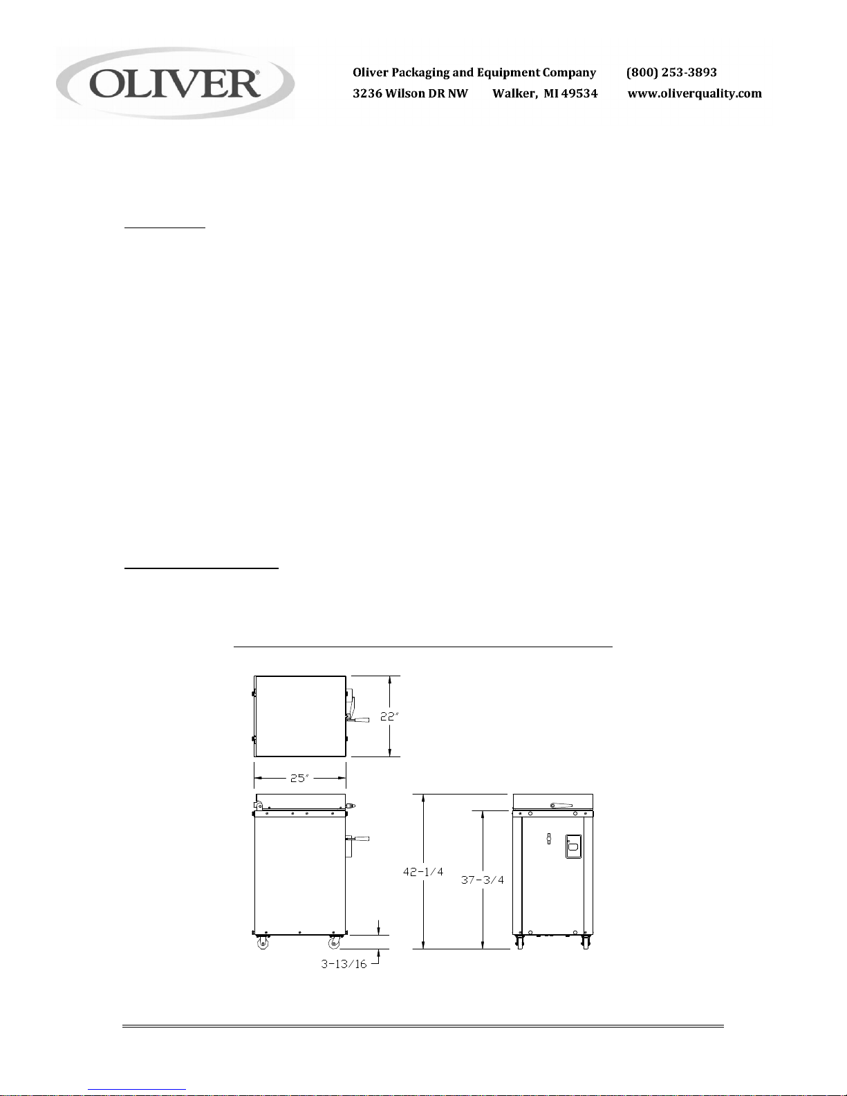
Physical specifications
OVERALL MACHINE DIMENSIONS
REV. 1-31-96
0619S20002-
1
Physical specifications (continued)
Net Weight:
Approximately 455 pounds.
Shipping Weight:
Approximately 500 pounds.
Product Capacities:
Fill Capacity (approximate) = 10-1/2 to 45 pounds
Divided piece Size (approximate):
16 part dividers = 10-1/2 to 45 ounces
20 part dividers = 8-1/2 to 36 ounces
24 part dividers = 7 to 30 ounces
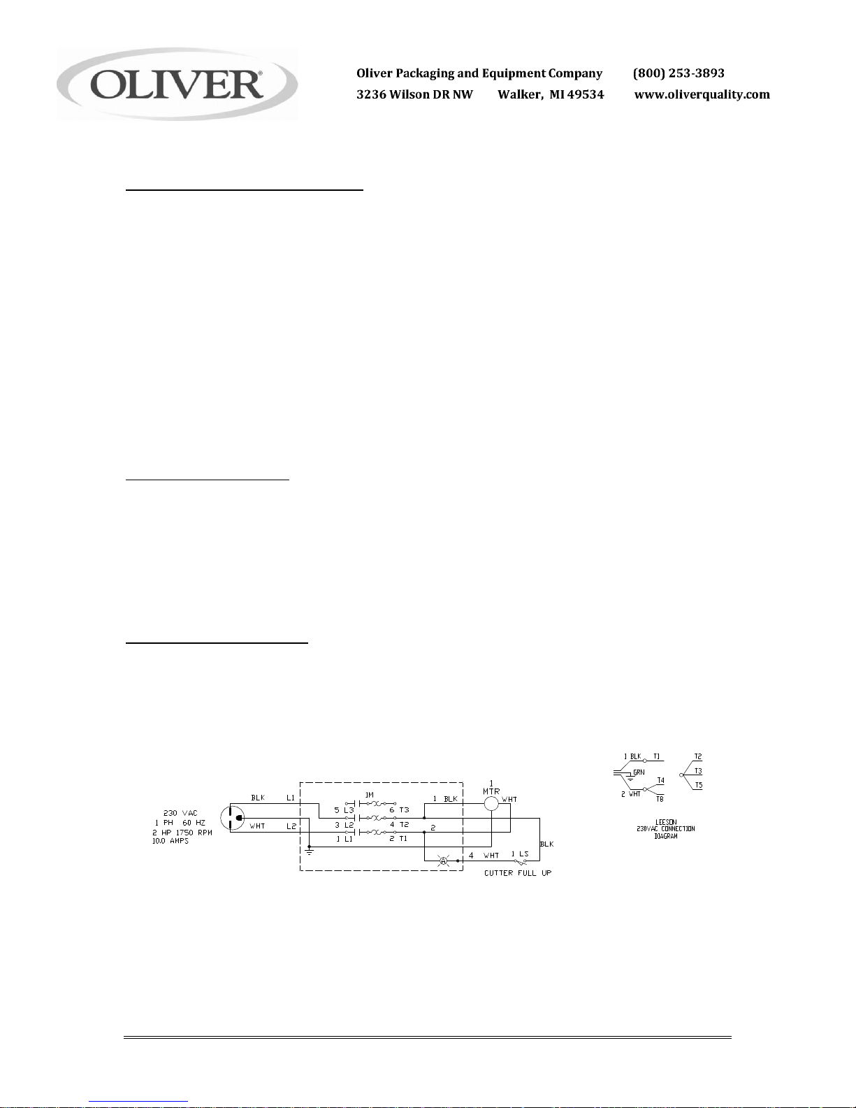
Electrical Specifications
2 Horse Power, 1 phase, 60 hertz, 230 Volts AC, 10 Amps.
2 Horse Power, 3 phase, 60 hertz, 208 Volts AC, 6.5 Amps.
2 Horse Power, 3 phase, 60 hertz, 230 Volts AC, 6.2 Amps.
2 Horse Power, 3 phase, 60 hertz, 460 Volts AC, 3.1 Amps.
Others consult factory
Electrical Wiring Diagrams
1 ph, 60 hz, 230 VAC
Rev. 1-31-96
0619S20002-
2
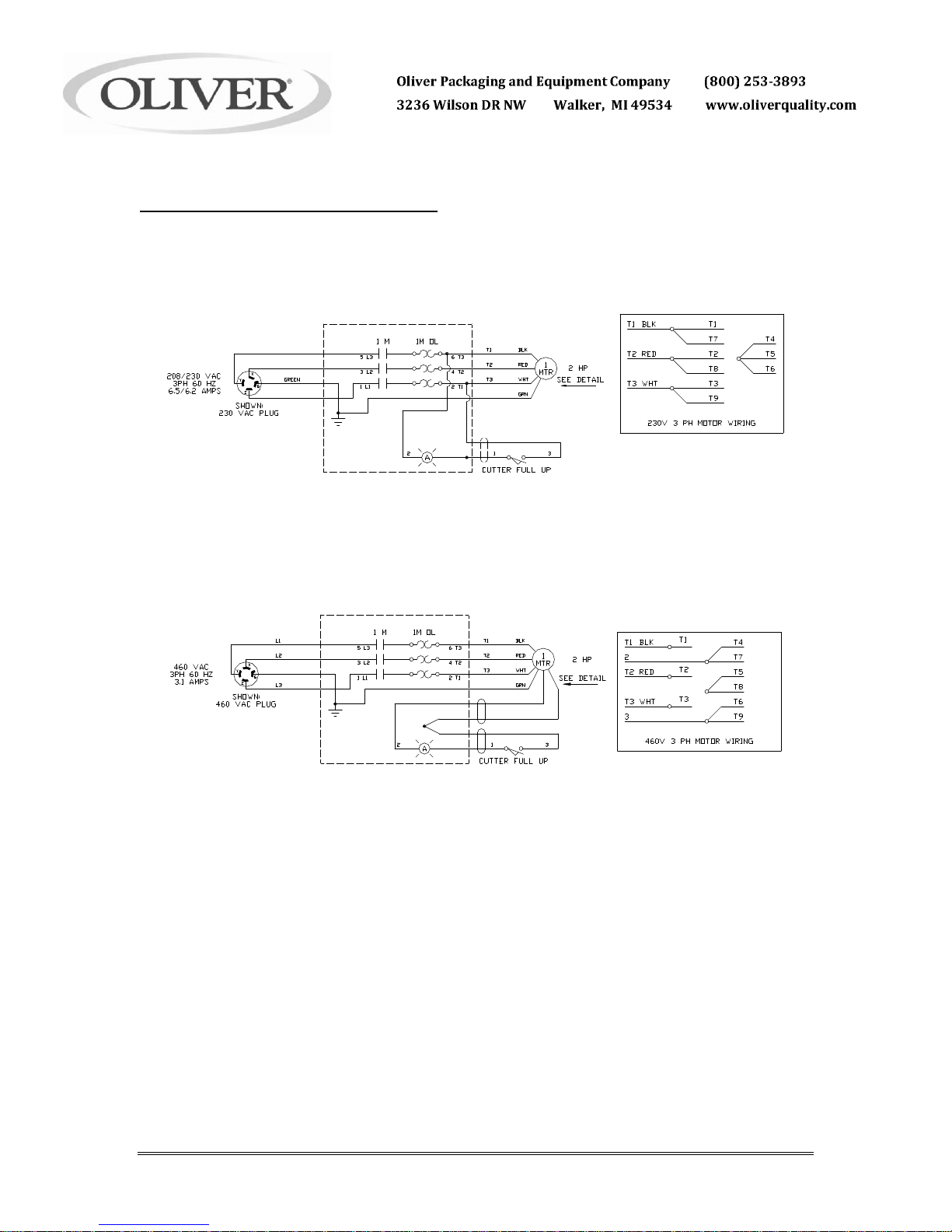
Electrical Wiring Diagrams (Continued)
3 ph, 60 hz, 208/230 VAC
3 ph, 60 hz, 460 VAC
Rev. 5-24-96
0619S20002-
3
MODEL 619-16, 20, 24, & 24R DOUGH DIVIDERS
OPERATING INSTRUCTIONS
Before You Start
CAUTION
THE DIVIDER SHOULD ONLY BE PLUGGED INTO AN OUTLET
WITH THE SAME VOLTAGE AS STATED ON THE NAMEPLATE
Before starting a new divider with THREE PHASE electrical power for the first time you
should check to see if the motor is running in the correct direction. Remove the front
cover by removing the four thumbscrews which secure it; you will also have to remove
the handle from the directional control lever before removing the front cover. Once the
cover has been removed you should be able to see the fan end of the motor on your
divider, this fan MUST rotate in a clockwise direction.
CAUTION
EXTENDED RUNNING OF A DIVIDER WITH THE MOTOR ROTATING
IN THE INCORRECT DIRECTION WILL SEVERELY DAMAGE THE
HYDRAULIC PUMP OF YOUR DIVIDER.
If the motor is rotating in the incorrect direction turn the machine off, disconnect it from
the power supply and have a qualified electrician reverse two of the three power wires
in the plug at the end of the power cord. DO NOT move the ground (green) wire.
WARNING
ALWAYS HAVE ELECTRICAL WORK DONE BY QUALIFIED ELECTRICIANS ONLY.
Recheck the divider making sure that it is now running in the correct direction,
(clockwise looking at the fan end of the motor).
Basic Operation
· Start by weighing out a piece of dough, which, when divided by the number of
compartments available on your divider, will provide you with the desired end
weight. For example: a thirty pound piece of dough after division on a twenty-four
part divider will yield twenty-four twenty ounce pieces, perfect for molding into one
and a quarter pound loaves of bread.
· Make sure the floor of the hopper has been lowered before attempting to open the
lid of the divider.
Rev. 5-5-00
0619S20003-
1
Basic Operation (Continued)
· Open the lid and load the preweighed dough into the hopper. Spread the dough
over the floor of the hopper making it approximately the same height, this is done to
eliminate large air pockets and to insure equal division of the dough.
· Close the lid and turn the handle in a clockwise direction making sure it is secure.
· With the machine running grasp the control valve handle and lift it to start the floor
of the hopper up. Hold it in this position until the light on the starter switch box
comes on, this means that the upward stroke has stopped and that division is
complete. Let loose of the valve handle when you see the light come on.
· Press the control valve handle down slightly to release the pressure on the lid so it
can be opened. Open the lid.
· We suggest that the cut pieces of dough be removed as soon as possible to
prevent them from sticking together.
· The above process may now be repeated.
WARNING
NEVER LEAVE DOUGH IN THE MACHINE; RISING DOUGH MAY
CAUSE EXPLOSIVE PRESSURES TO DEVELOP.
WARNING
NEVER FORCE THE LID HANDLE OPEN
· If dough has been left in the machine and the lid handle is difficult to turn,
recompress the dough by lifting the control valve handle until the light come on.
This will raise the floor of the hopper, after doing so lower the hopper floor by
pressing down on the control valve handle. This may have to be done more than
once if dough has been left in the machine for quite awhile. With the hopper floor
all the way down try to open the lid again, the handle should turn easily, if it does
not, recompress the dough and try again.
· The divider is designed so that if dough is left in the hopper it will eventually force
the hopper’s floor to the bottom, thus allowing the dough to vent to the outside of
the machine through openings on the left side. If dough is coming out of these
openings follow the steps above recompressing the dough a number of times
before attempting to open the lid.
Rev. 5-5-00
0619S20003-
2
MODEL 619-16, 20, 24, & 24R DOUGH DIVIDERS
MAINTENANCE
WARNING
ALWAYS MAKE SURE THE MACHINE HAS BEEN DISCONNECTED
FROM THE POWER SUPPLY BEFORE CLEANING OR SERVICING.
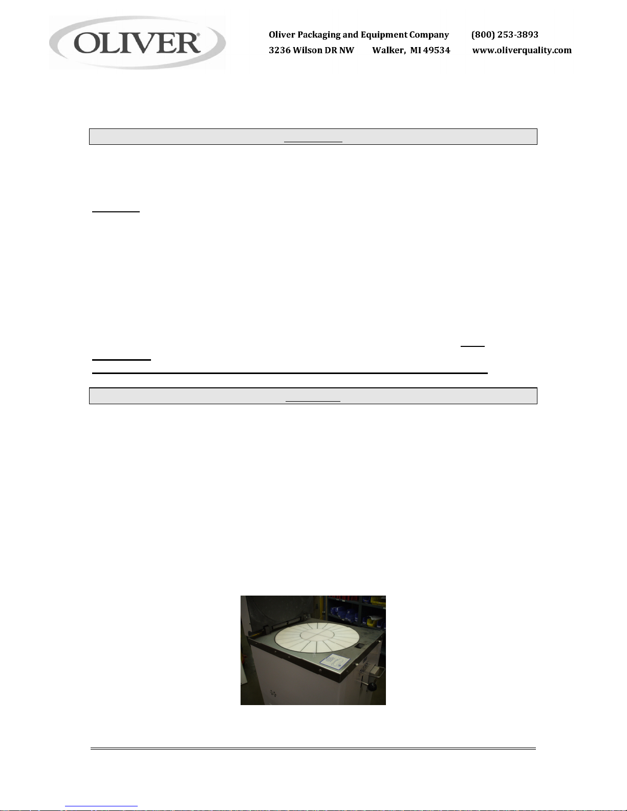
Cleaning
Remove- all scraps from lower pan. Open side doors and brushing out all scraps. Wash all
interior surfaces; Knives, pusher plates, hopper, lid surface with a damp rag and mild soap
solution. The exterior and contact surfaces should be cleaned daily using common cleaners.
The knives should be extended for easier cleaning. This can be done by placing the cleaning
separator, furnished with the machine, IN THE CENTER OF THE HOPPER straddling the
knives. Close the lid and bring the floor of the hopper up until the light on the manual starter is
on, lower the floor slightly. Open the lid and disconnect the divider from the power supply.
Clean the knives and plastic compartment floors of all dough build-up. Rinse all interior surfaces
with a damp rag and clean water. Sanitize all interior surfaces with a damp rag and sanitizing
solution. Air Dry, leave divider lid open and allow interior to air dry before using. SEE
CLEANING
INSTRUCTION SHEET (S20143) AT THE END OF THIS CHAPTER (S20004)
CAUTION
IF NOT CLEANED A BUILD-UP OF DRIED DOUGH BETWEEN THE
PLASTIC FLOORS AND THE KNIVES COULD DAMAGE THE DIVIDER.
In addition to the general cleaning discussed above, it is important that you check for and
remove scraps of dried dough from between the blade holder and the bottom thrust plate. This
can be done by first extending the knives as described above and then by removing the front
cover from the machine by removing the four knobs and the control valve handle. This will allow
access to the blade holder area which can then be cleaned of all dried scraps of dough. When
finished replace the front cover.
Occasionally, as required, you should also remove the build up of flour and dough
particles in the base of the machine around the motor.
CLEANING INSTRUCTIONS FOR THE 619
0619S20149-
1
RUN PRESS ALL THE WAY UP
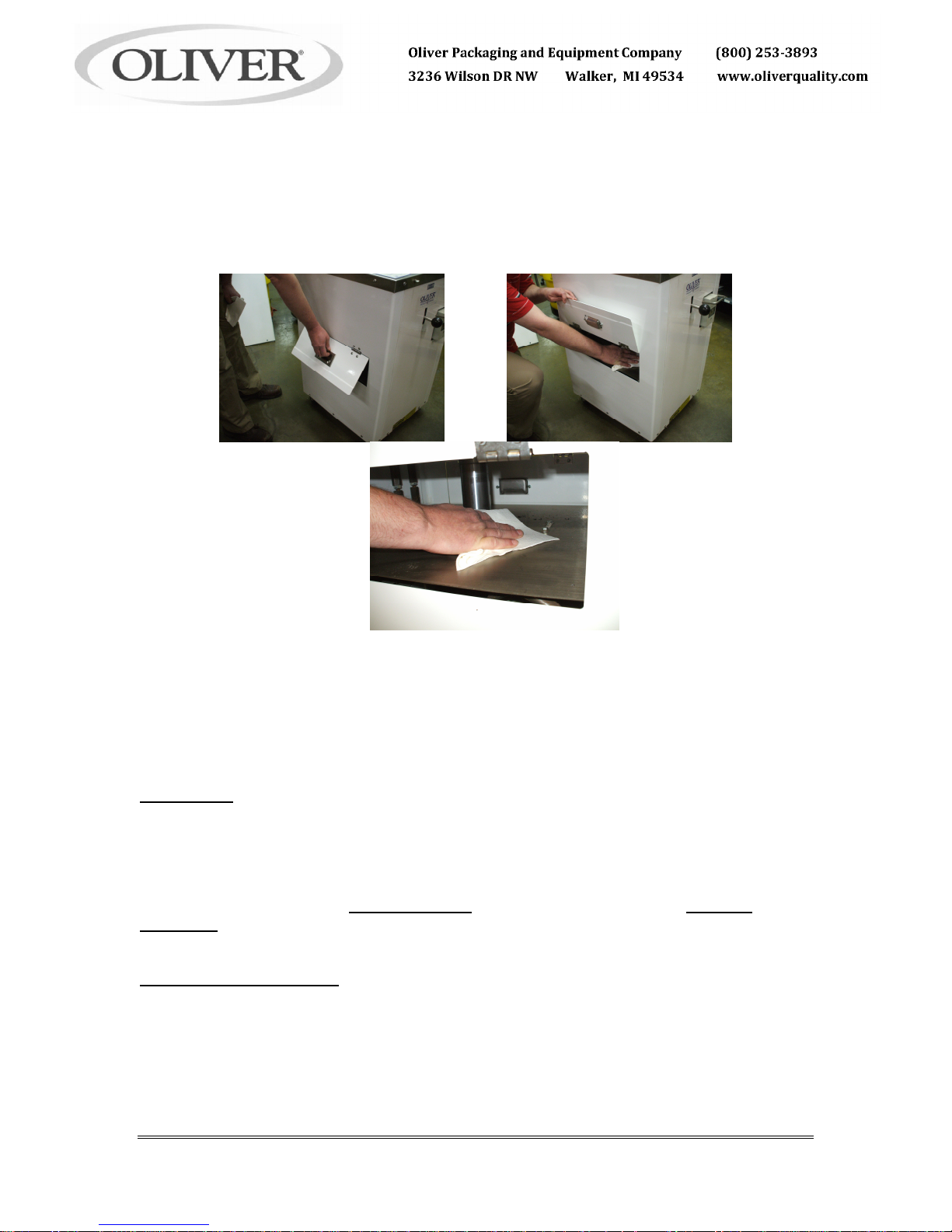
*********W A R N I N G******
UNPLUG MACHINE
USING THE ACCESS DOORS ON BOTH SIDES OF THE UNIT
PULL DOOR UP, USE ONE HAND TO HOLD DOOR UP
WIPE DOWN MACHINE WITH OTHER, USING A RAG
OR A BRUSH
Lubrication
The machine requires no lubrication but the oil level in the hydraulic system should be checked
periodically. To check the oil level remove the rear cover by removing the four knobs which
secure it to the divider, then remove the tank breather/cap and determine where the top of the oil
is in relation to the top surface of the tank. Fill with oil to within approximately one inch of the
top surface. If necessary add HYDRAULIC OIL to return it to the proper level, DO NOT
OVERFILL. In addition to the above we advise replacing the hydraulic oil in the system
approximately every three years.
Hydraulic Oil Specification
The hydraulic oil used in your divider should be made of good quality base stocks compounded
with the following additives: anti-wear, anti-oxidation, antifoaming, and antirust. In addition it
should be an “ISO” viscosity grade No. 32.
Rev. 7-30-02
0619S20149-
2

Hydraulic Filter Replacement
At least once a year the throw-away filter on the hydraulic system should be replaced, more
often when under heavy use. To replace the filter remove the front cover unscrew the old filter
and replace it with a new one. The filter is located on the return line near the tank.
Removing The Lid
· Remove the lid cover by removing the four screws which secure it in position.
· Open the lid as far as it will go.
· Release the tension on the two large torsion springs by moving the long leg of the spring to
the side and out from behind the bracket.
WARNING
USE CARE AS THE LID WILL DROP ONCE THE SPRING TENSION
HAS BEEN REMOVED.
· Close the lid and remove the right hand snap ring from the lid hinge pin and push the pin to
the left to remove it.
· Reassemble by reversing the above steps.
Replacing The Locking Hook Or Cam:
· Remove the lid cover by removing the four screws which secure it in position.
· Detach the spring from the hook.
· Open the lid.
· Turn the handle until the pin securing the cam to the shaft is in line with the notch in the
locking hook. Using a small drift punch force the pin upwards removing it from the handle
shaft.
· Pull the shaft and cam assembly forward out of the lid.
· The hook or locking cam can now be replaced.
· Reassemble by reversing the above steps.
Replacing A Plastic Bottom Element
· Open the lid and raise the bottom of the hopper.
· Turn the machine off and disconnect it from the power supply.
· Remove the front and rear panels to gain access to the pusher components.
0619S20149-
3
 Loading...