

Oliver M-1013, 1013 intelliCarve Owner's Manual
1
1013 intelliCarve
Owner’s Manual
Oliver Machinery M-1013 7/2011
Seattle, WA Copyright 2003
info@olivermachinery.net www.olivermachinery.net

2
Warranty
Oliver makes every effort possible to assure that its equipment meets the highest possible standards of
quality and durability. All products sold by Oliver are warranted to the original customer to be free from
defects for a period of 2 (two) years on all parts, excluding electronics and motors, which are warranted for
1 year. Oliver’s obligation under this warranty shall be exclusively limited to repairing or replacing (at Ol-
iver’s option) products which are determined by Oliver to be defective upon delivery F.O.B. (return freight
paid by customer) to Oliver, and on inspection by Oliver. This warranty does not apply to defects due,
directly or indirectly, to misuse, abuse, negligence, accidents, unauthorized repairs, alterations, lack of
maintenance, acts of nature, or items that would normally be consumed or require replacement due to
normal wear. In no event shall Oliver be liable for death, personal or property injury, or damages arising
from the use of its products.
Warning
Read this manual thoroughly before operating the machine. Oliver Machinery disclaims any liability for
machines that have been altered or abused. Oliver Machinery reserves the right to effect at any time,
without prior notice, those alterations to parts, fittings, and accessory equipment which they may deem
necessary for any reason whatsoever.
For More Information
Oliver Machinery is always adding new Industrial Woodworking products to the line. For complete,
up-to-date product information, check with your local Oliver Machinery distributor, or visit
www.olivermachinery.net

3
WARNING
Read this manual completely and observe all warning labels on the machine. Oliver Machinery has made
every attempt to provide a safe, reliable, easy-to-use piece of machinery. Safety, however, is ultimately the
responsibility of the individual machine operator. As with any piece of machinery, the operator must exercise caution, patience, and common sense to safely run the machine. Before operating this product,
become familiar with the safety rules in the following sections.
This machine is designed for acrylic and wood carving only. This unit cannot be modified and used for any
application other than for which it is designed. Any modification may result in a serious injury and will void
all warranties. Please read and understand all warnings and operating instructions. Basic safety precautions should be followed to avoid the risk of personal injury when operating the machine.
1. Do not block the Emergency Stop Button.
2. To reduce the risk of electric shock, do not operate the machine with wet hands.
3. Do not wear gloves when operating the machine.
4. Before turning the power on, make sure the surroundings are clear of obstacles.
5. When you turn the power on, the axis return to the Home Point coordinates automatically.
6. Avoid the risk of danger; not play or run in the work area.
7. Do not touch the spindle or cutting tools with bare hands before the machine is completely stopped.
8. Pay attention to the warning labels. Replace the warning labels if they become illegible or are missing.
9. Always power off the machine when you finish your work.
10. Please install and remove the bit as instructed.
11. Ensure the power is off before installing a new cutting tool.
12. Please install the software and the unit as instructed.
13. To avoid the risk of danger, make certain that the object you are carving is properly secured.
14. Do not remove any debris that cover the axis while the unit is operating.
15. Always ensure that the size of the workpiece is proper for intelliCarve.
16. To ensure safety, all maintenance should be made by a knowledgeable technician.
17. To ensure safety, be sure to properly ground any extension cord that is used.
18. To ensure safety, do not tamper with the safety cover, limit switch or any other accessories.
19. To avoid electrical shock, do not touch transformers, motors and control box when the power is on.
20. Unplug the power before replacing any fuse. Be sure to use the recommended fuse.
21. Be sure to turn off the machine when the power source is unstable.
22. Be sure to keep a record before changing any settings of the machine.
23. Place the unit in a sturdy place and dry area.
24. Avoid extremely high temperatures.

4
Table of Contents Page Number
Warranty ....................................................................................................................................................... 2
Safety and Warnings ................................................................................................................................... 3
Table of Contents ......................................................................................................................................... 4
Overview ....................................................................................................................................................... 5
Specifications .......................................................................................................................................... 7-8
Unpacking Your intelliCarve ....................................................................................................................... 9
Standard Packaging ................................................................................................................... 9
Getting to Know Your intelliCarve....................................................................................................... 10-11
The Components ...................................................................................................................... 10
X/Y/Z Axis System .................................................................................................................... 11
Install The Cutting Tool ............................................................................................................................. 12
Cutting Tools ........................................................................................................................................ 13-14
Conical Bit ................................................................................................................................ 13
End Mill Bit ............................................................................................................................... 14
Installing i-Picture Software ..................................................................................................................... 15
Using i-Picture ..................................................................................................................................... 15-18
Getting Ready To Carve .................................................................................................................... 19-23
Powering Up ............................................................................................................................ 19
Setting the Work Piece On The Table ....................................................................................... 20
Using The Control Panel ..................................................................................................... 21-23
Tips .............................................................................................................................................................. 24
Advanced Operations.......................................................................................................................... 25-28
CAD/CAM Software ................................................................................................................... 25
Origin Repeat ............................................................................................................................ 25
Positioning By Coordinate ......................................................................................................... 26
Turn Spindle On/Off In Manual Jog Mode ................................................................................. 27
Changing Units from Metric to Imperial ..................................................................................... 28
Troubleshooting ................................................................................................................................... 29-32
5
Overview
Software
i-Picture is free software for the intelliCarve series that can automatically output NC code from image files
such as jpg, png, gif or bmp files. Oliver Machinery will continue to review the software and will provide new
releases when available at no charge to the original owner.
intelliCarve
With the output NC code from i-Picture, the intelliCarve is a very unique engraving machine that allows the
user to transfer digital images or photographs onto a material such as wood, corian, acrylic or plastic.
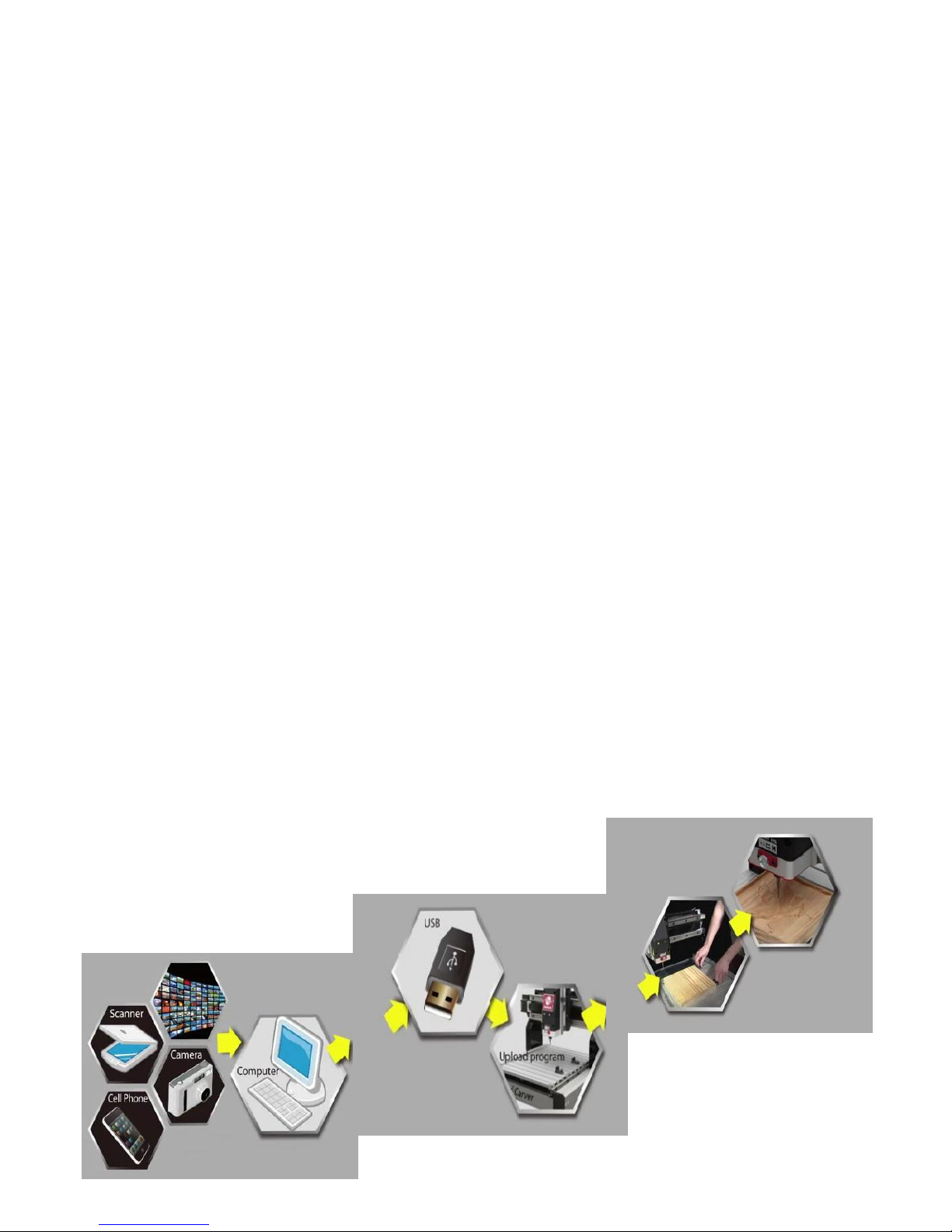
What makes the intelliCarve so unique?
1. Easy
intelliCarve users only need plug the USB into the intelliCarve, then select a file for carving and push a few
buttons to complete the carving. Knowledge of CAD/CAM software is not necessary.
2. Light
i-Picture comes free with the intelliCarve and does not need a high level computer system to operate such
as what is usually needed for CAD/CAM software. And iCarver is only 62lbs!
3. Versatile
For users with CAD/CAM capabilities, i-Picture will accept G code from after market software providers to
aid in the creation of simple 2D or 3D carvings, signs, or decorative mouldings *.
*request a ‘post processor file’ from your CAD/CAM software provider to run the intelliCarve machine.
Note: Oliver does not guarantee the outcome of the work piece due to
the table movement of the Y-axis.

6
Technical Features
Easy picture engraving by i-Picture’s intuitive picture to g-code convertor
File transferred to intelliCarve via USB flash drive
Pause function during carving
Repeatable origin
Adjustable jog speed in manual mode
Adjustable carving speed
Metric/Imperial system available
Supports manual carving without program
Maximum engraving area simulation
Supports file category tree structure
Spindle and stepper motors overload protection
Support images in bmp/jpg/gif/png format
Percentage display for carving time completion
Auto parameters optimization
Reliable BLDC (brushless, DC) spindle motor
Wood/plastic engraving
Dust impact free drive structure
Light aluminum ght structure

7
1013 intelliCarve
Item
Description
Spec
1
Travel
1.1
X axis
331mm(13")
1.2
Y axis
457mm(18")
1.3
Z axis
76mm(3")
2 Tool
2.1
shank OD
¼”
2.1
cutter
conical R1/32” (0.8mm) / end mill D1/8” (3.2mm)
2.2
Cut depth
Max 25.4mm(1")
3
Spindle
3.1
speed
15000rpm
3.2
motor
150w DC brushless
4
Transmission
4.1
X/Z lead screw diameter
16mm(0.63”)
4.2
X/Z rail material
IGUS WX-01-10
4.3
Y axis
Rack & pinion
6 Feed Speed
6.1
speed
3M/min(118in/min)
6.2
position accuracy
0.1mm (0.004”)
6.2
reposition accuracy
±0.1mm (0.004”)
7
Step motor
7.1
Max torque
17.3 kg-cm(15lb-in)
7.2
step angle
1.8 °
7.3
voltage(Max.)
24V/Phase
7.4
current(Max.)
2.8 A/Phase
8 Sensor
8.1
no of sensors(X/Y/Z)
2/2/2
9
Control Interface
9.1
LCD
(46x30)mm
9.4
keypad
10 keys
9.6
interface
USB Port × 1
Specifications

8
Specifications (cont.)
10
Dimension & Weight
10.2
Space (WxL)
630x560x530mm(25.8x22.0x20.8”)
10.3
weight
28 Kg 61.6lbs
11
Others
11.1
power in
AC 110V 6A 50~60Hz
11.3
software
i-Picture for intelliCarve
9
Unpacking Your intelliCarve
Please unpack your intelliCarve with care. If you discover the machine has been damaged, please report
the damage to the freight carrier.
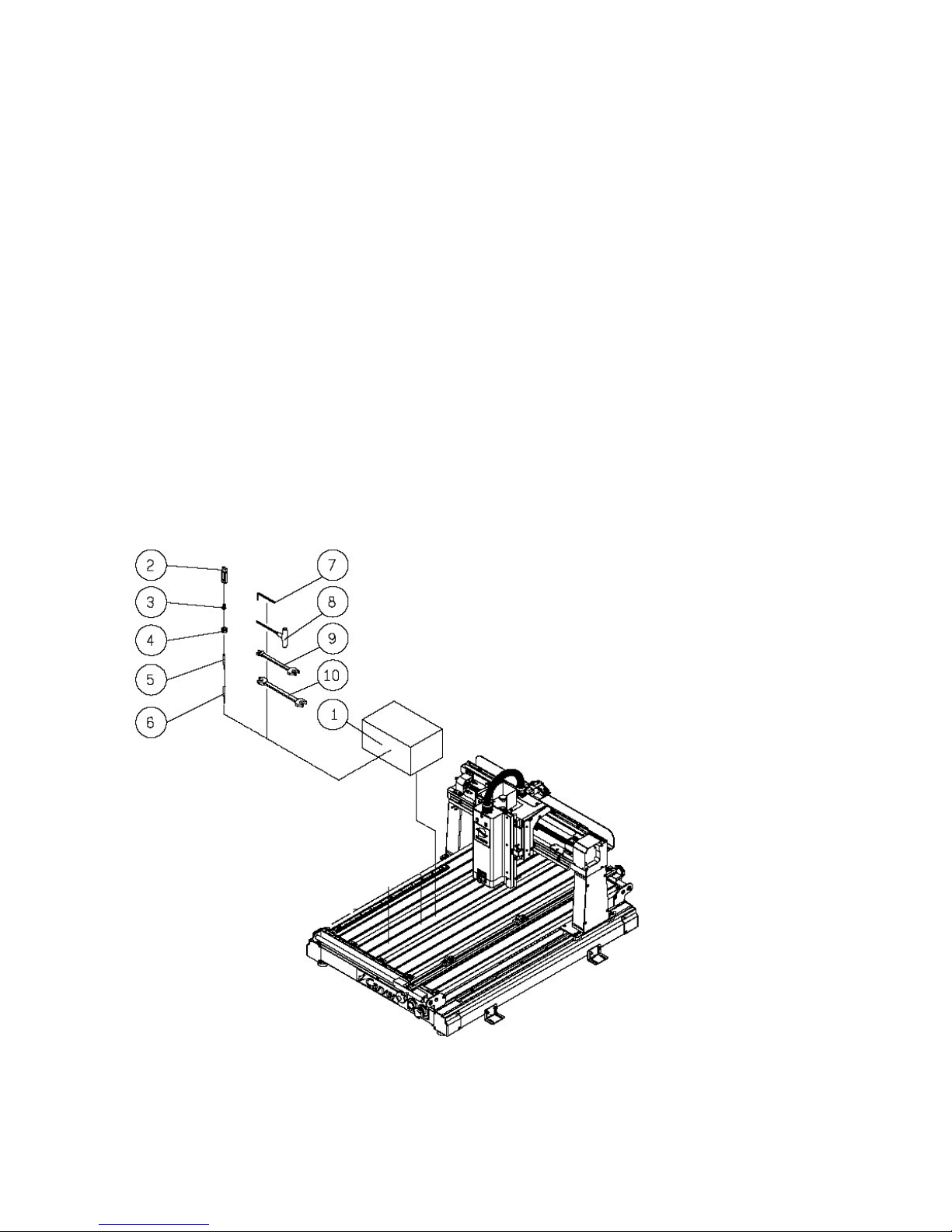
Standard Packaging
1. Tool Box
2. USB flash drive
- I-picture software
- 3D sample pictures
3. ¼” collet
4. Collet nut
5. Conical bit, 0.8mm Radius
6. End mill bit, 3.2mm Diameter
7. 4mm T wrench
8. 5mm Hex wrench
9. Double wrench 11*13mm
10. Double wrench 14*17mm
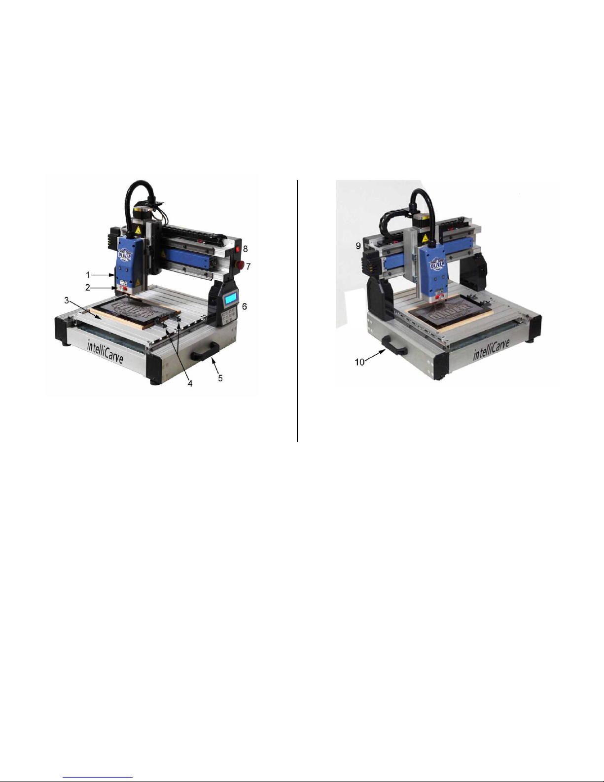
10
1. Spindle motor
7. Emergency stop
2. Spindle lock
8. Power switch
3. Table
9. USB port
4. Work piece hold downs
10. Lift handle (left)
5. Lift handle (right)
6. LCD display and controller
Fig. 3
Fig. 2
Getting to Know Your intelliCarve
The Components (see Fig. 2-3)
11
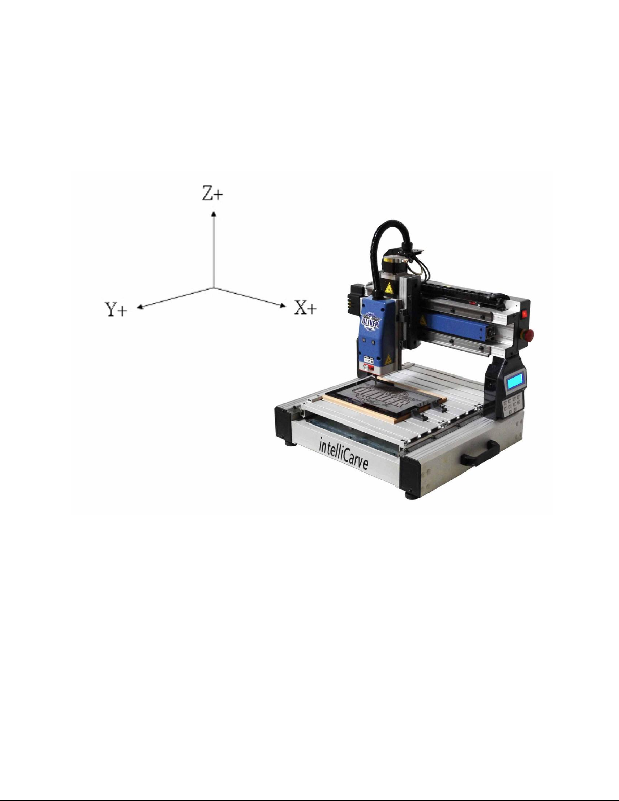
The Axis System
The axis movements are defined according to the operator’s position (facing the front spindle).
Directional Conventions
1. + X: spindle head moves right
2. - X: spindle head moves left.
3. +Z: spindle head moves up.
4. - Z: spindle head moves down.
5. +Y: table moves toward operator.
6. - Y: table moves away from operator.
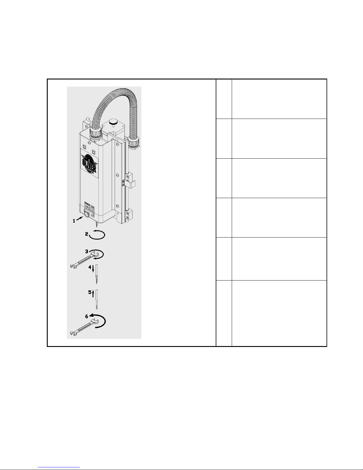
12
1
Press pin slightly.
2
Rotate spindle while pressing the
pin in order to engage the lock.
3
Loosen the nut with an open end
wrench turning clockwise.
4
Release the bit.
5
To install a new bit, place the
collet into the nut. Then put the bit
into the nut and collet. Screw the
assembly onto the spindle.
6
Lock the bit with an open end
wrench turning counterclockwise.
Installing the Cutting Tool
 Loading...