

Page 1

ORION 700
I MANUALE USO E MANUTENZIONE GB OPERATOR’S INSTRUCTION BOOK
Page 2

Page 3

Italiano
ISTRUZIONI ORIGINALI
5
English
TRANSLATION OF ORIGINAL INSTRUCTIONS
43
Page 4

Page 5

Function keys and menu items
English
Item Name Item Name
1 HOME key 6 START/PAUSE key
2 LCD display 7 Multifunction key right
3 STOP key 8 Multifunction key left
4 Up arrow key 9 ON/OFF key
5 Down arrow key 10 Menu key
Refer to the speci ed pages for information about calling up the various menu items and for the descriptions of them.
Chapter/page
„Start-up“ see page 58
„Setting the time“ see page 67
„Setting the date“ see page 67
„Setting the language“ see page 68
„Enter PIN code“ see page 59
„Changing the PIN code“ see page 59
„Activate or deactivate the button tones“ see page 68
„Changing the display contrast on the LCD display“ see page 69
„Restoring factory settings“ see page 69
„Setting the week program“ see page 66
43
Page 6
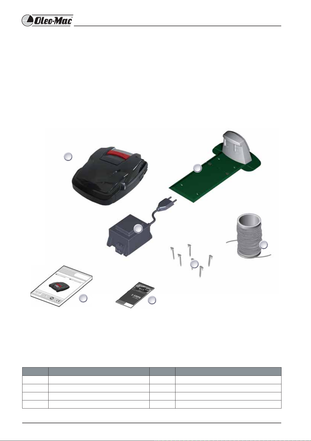
1 Scope of supply
1.1 Unpacking the machine
Carefully unpack the robot lawnmower and its components and check everything for damage in transport. If there is any
transport damage, immediately notify your dealer.
If the robot lawnmower was sent by a parcel service, retain the original packaging and accompanying documents.
1.2 Scope of supply
1
2
3
5
6
7
Item Name Item Name
1 Robot lawnmower 5 Lawn pegs (100 pcs.)
2 Base station 6 Instructions for use
3 Transformer 7 Quickstart guide
4 Boundary cable (100 m)
4
44
Page 7

Contents
1 Scope of supply .............................................................................................................................................................. 44
1.1 Unpacking the machine ..........................................................................................................................................................................44
1.2 Scope of supply .........................................................................................................................................................................................44
2 About this product ......................................................................................................................................................... 48
2.1 Designated use .......................................................................................................................................................................................... 48
2.2 Prohibited use............................................................................................................................................................................................48
3 Safety notes ................................................................................................................................................................... 48
3.1 Explanation of symbols ...........................................................................................................................................................................48
3.2 General safety notes ................................................................................................................................................................................49
3.3 Safety notes for operation ......................................................................................................................................................................49
4 Product information ..................................................................................................................................................... 50
4.1 Product description .................................................................................................................................................................................. 50
4.2 Description of function ........................................................................................................................................................................... 50
4.3 Control panel ............................................................................................................................................................................................. 51
4.4 Sensors in the robot lawnmower .......................................................................................................................................................... 51
4.5 Base station ................................................................................................................................................................................................52
4.6 Transformer ................................................................................................................................................................................................ 52
4.7 Boundary cable .........................................................................................................................................................................................52
5 Assembly/installation .................................................................................................................................................... 53
English
5.1 Assembling the base station .................................................................................................................................................................. 53
5.2 Setting up the base station .................................................................................................................................................................... 53
5.3 Laying the boundary cable .................................................................................................................................................................... 54
5.4 Laying options ...........................................................................................................................................................................................55
5.5 Laying the cable around obstacles ....................................................................................................................................................... 56
5.6 Connecting the boundary cable to the base station .......................................................................................................................56
5.7 Connecting the low-voltage cables to the transformer .................................................................................................................. 56
5.8 Opening the cover on the rear of the base station ..........................................................................................................................57
5.9 Checking the connection ........................................................................................................................................................................ 57
45
Page 8

6 Start-up .......................................................................................................................................................................... 58
6.1 Preparations ...............................................................................................................................................................................................58
6.2 Switching on/status display ...................................................................................................................................................................58
6.3 Language selection .................................................................................................................................................................................. 58
6.4 Enter PIN code ........................................................................................................................................................................................... 59
6.5 Changing the PIN code............................................................................................................................................................................59
6.6 Setting/changing the date .....................................................................................................................................................................59
6.7 Setting/changing the time .....................................................................................................................................................................60
6.8 Calibration .................................................................................................................................................................................................. 60
6.9 Starting the robot lawnmower .............................................................................................................................................................. 61
7 Mowing .......................................................................................................................................................................... 62
7.1 Mowing tips ...............................................................................................................................................................................................62
7.2 Setting the cutting height ......................................................................................................................................................................62
7.3 Charging the battery in the robot lawnmower ................................................................................................................................. 62
7.4 Exhaustively discharged battery ........................................................................................................................................................... 63
8 Programming ................................................................................................................................................................. 64
8.1 Starting the robot lawnmower .............................................................................................................................................................. 64
8.2 Overview ..................................................................................................................................................................................................... 65
9 Program menu ............................................................................................................................................................... 66
9.1 Setting the week program ...................................................................................................................................................................... 66
10 Setting menu ................................................................................................................................................................. 67
10.1 Setting the time ........................................................................................................................................................................................67
10.2 Setting the date ........................................................................................................................................................................................ 67
10.3 Setting the language ...............................................................................................................................................................................68
10.4 Further setting possibilities .................................................................................................................................................................... 68
10.5 Activate or deactivate the button tones. ............................................................................................................................................ 68
10.6 Changing the display contrast on the LCD display ........................................................................................................................... 69
10.7 Restoring factory settings....................................................................................................................................................................... 69
46
Page 9

11 Information menu .......................................................................................................................................................... 69
11.1 Hardware information ............................................................................................................................................................................. 69
11.2 Software information............................................................................................................................................................................... 70
12 Program information ..................................................................................................................................................... 70
13 Transport ....................................................................................................................................................................... 70
14 Maintenance .................................................................................................................................................................. 71
14.1 Check the rollers can move freely ......................................................................................................................................................... 71
14.2 Checking/cleaning contacts .................................................................................................................................................................. 71
14.3 Checking/cleaning the base station .................................................................................................................................................... 72
14.4 Cleaning the chassis ................................................................................................................................................................................. 72
15 Repair ............................................................................................................................................................................. 72
15.1 Renewing the cutting blade plate ........................................................................................................................................................ 72
16 Technical data ................................................................................................................................................................ 73
17 Help in case of malfunctions ......................................................................................................................................... 74
17.1 Examples of fault messages ................................................................................................................................................................... 74
17.2 Troubleshooting ........................................................................................................................................................................................ 75
17.3 Interactive help .........................................................................................................................................................................................78
18 Warranty ........................................................................................................................................................................ 78
19 Disposal .......................................................................................................................................................................... 79
20 Declaration of conformity ............................................................................................................................................. 79
English
47
Page 10
2 About this product
Important
Comply with the safety and warning instructions in these
instructions for use, and on the robot lawnmower.
These instructions for use are a permanent component
of the described product, and should remain with the
machine if it is sold to someone else.
Only experienced persons who are familiar with the
operation and safe use of this machine should use it. Give
other users the manual with operating instructions, which
they should read before using.
2.1 Designated use
The robot lawnmower is exclusively intended for mowing
private lawns.
Any other use is regarded as not in accordance with the
designated use.
2.2 Prohibited use
1. The robot lawnmower is not suitable for use in commercial
enterprises, public facilities, parks, sports facilities or in
agriculture and forestry.
2. The robot lawnmower must not be used for cutting other
materials, particularly materials above ground level that
require the lawnmower to be raised above the ground.
A dangerous situation that could lead
to damage to the machine.
Note!
Explanatory description that is useful for understanding the
work or the operating procedure to be carried out.
2
1
4
56
7
89
0
쐅
쐉
씈
씉
3. The robot lawnmower must not be used to shred branches,
nor materials thicker than grass.
4. The robot lawnmower must never be used to transport,
push or tow trailers or other similar objects.
5. It is prohibited to t implements or accessories other than
those supplied by the manufacturer.
3 Safety notes
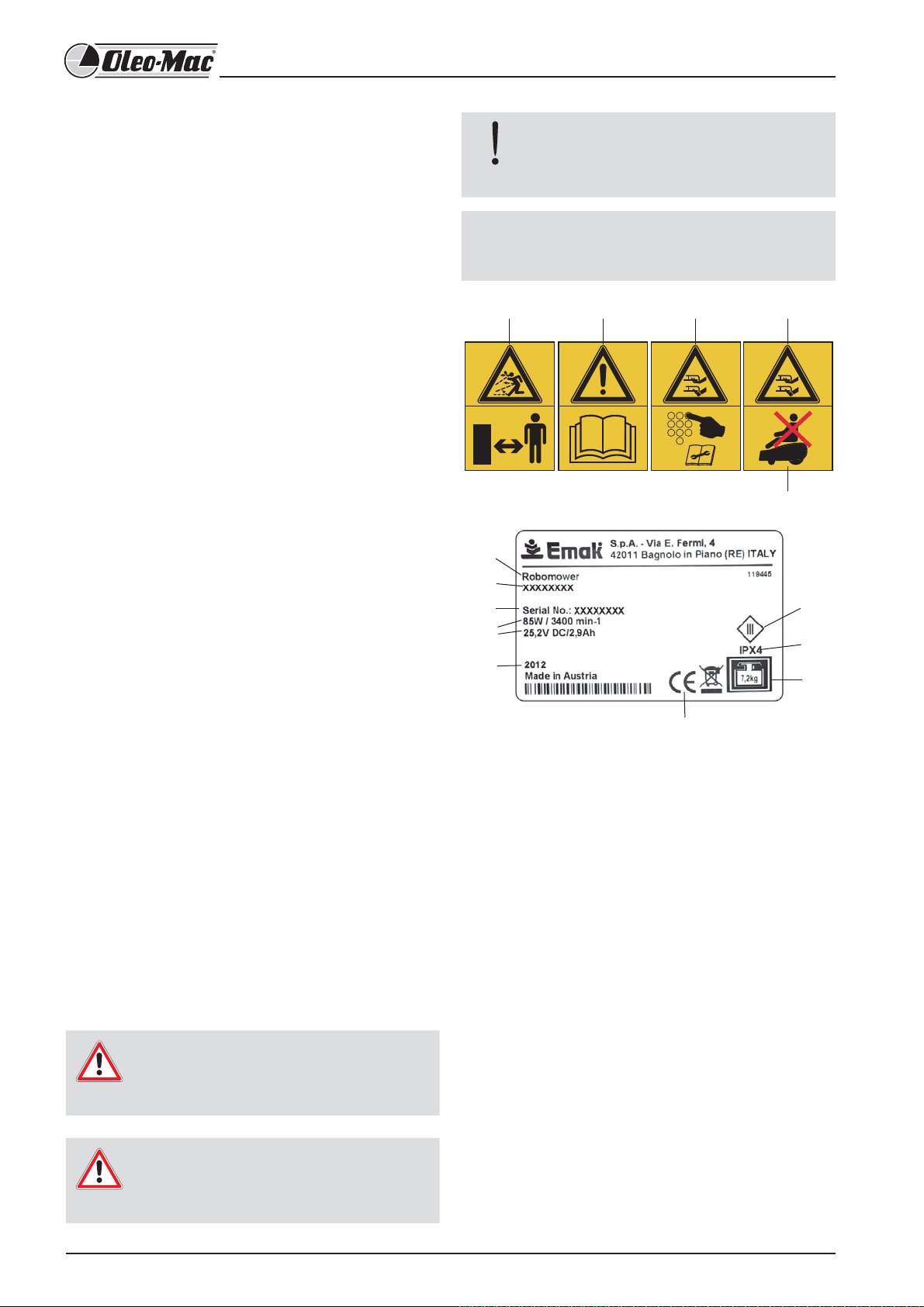
3.1 Explanation of symbols
The following safety notes are used in these instructions for
use. The signal word used depends on the particular risk.
Warning!
Warning about a potential danger that
could lead to serious or fatal injuries.
Caution!
A dangerous situation that could lead
to injury.
쐈
1 - WARNING! - Do not let anybody approach to the
working area. Be careful of thrown objects
2 - Read operator’s instruction book before operating
this machine.
3 - Be careful of the cutter blades when adjusting or
servicing the machine.
4 - Be careful of the cutter blades when operating the
machine.
5 - DO NOT stand on the robotic lawn mower.
6 - Type of machine: ROBOT LAWNMOWER
7 - Machine brand and model
8 - Serial number
9 - Specifications
10 - Year of manufacture
11 - CE conformity marking
12 - Class 3 appliance.
13 - Protection class of the machine.
14 - Weight of the machine.
48
Page 11

Safety devices
3.3 Safety notes for operation
Safety devices are not allowed to be bypassed, manipulated
or removed. Failure to comply can endanger your own
health and that of other people.
The robot lawnmower is protected by a PIN code in order
to prevent it from being switched back on inadvertently or
without authorisation.
The robot lawnmower is supplied from the factory with the
PIN code 0000.
A PUK code must be entered if the PIN code is entered
incorrectly three times. Request this from your dealer.
The robot lawnmower is equipped with a safety sensor.
If the robot lawnmower is lifted up, its motor and cutting
blades are stopped within 2 seconds.
After contact with an obstacle, the robot lawnmower
moves back, stops and changes its direction of travel.
3.2 General safety notes
The owner is responsible for accidents involving other people
and their property.
Warning!
Switching on inadvertently or unauthorised
use can lead to extremely serious injuries.
The robot lawnmower must be switched o
and secured with a PIN code.
Note!
Keep the PIN code and PUK code where they cannot
be accessed by unauthorised people.
The PIN code can be changed by the owner.
If the PIN code is entered incorrectly three times, it will
be necessary to enter a PUK code.
If the incorrect PUK code is entered you must wait 24
hours before making a repeat attempt.
Regularly check the robot lawnmower and the base station
for damage.
The replacement or repair of damaged components and
batteries should be entrusted to specialist workshops
approved by the manufacturer.
English
Caution!
Danger of injury.
Do not deactivate safety and protective
devices.
The robot lawnmower is not allowed to be operated by
anyone who has not mastered safe handling of the robot
lawnmower and/or has not read and understood the
instructions for use.
During mowing, make sure that no-one places any part of
their body in the vicinity of the rotating cutting blades.
If the robot lawnmower is defective, e.g. on its cutting
blade(s), cable or base station, then do not take it into
operation.
Have the defects repaired pro ciently.
Warning!
Take maximum care to ensure that children
and animals are never allowed near the
machine.
Do not allow children to play with the device
Note!
Never carry out operations or repairs on your own that
are other than routine maintenance. Call specialised
and authorised workshops only.
49
Page 12
4 Product information
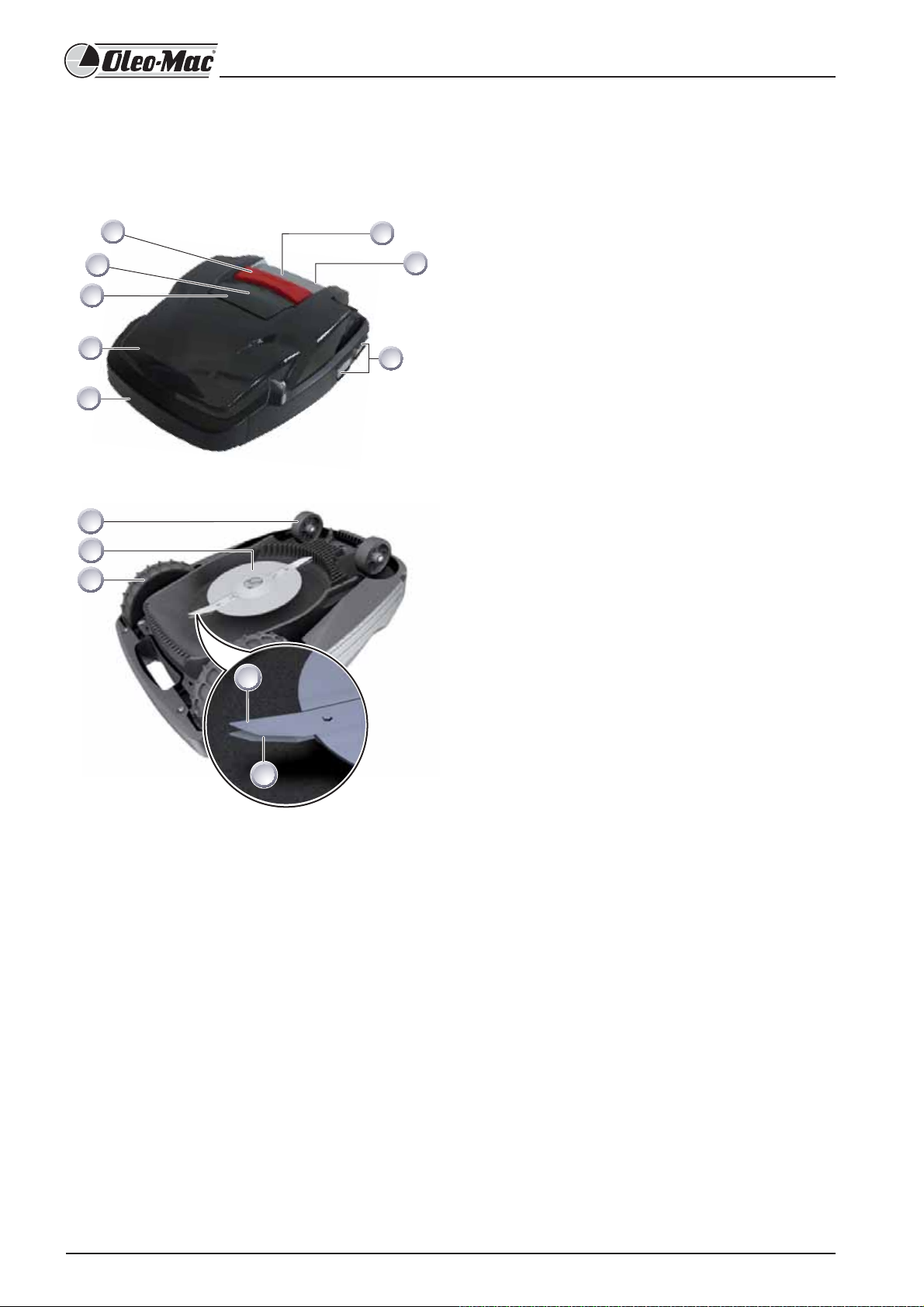
4.1 Product description
1 Control panel
2 Carry handle
3
Charging contacts
8
7
6
1
2
4
5 Housing
6 Cover plate ( ap for height adjustment)
Bumper
7 Height adjustment interior
5
4
3
8 STOP key
9 Front wheels
10 Blade plate
11 Drive wheels with high-grip tread
12/13 Cutter/clearer blades
9
10
11
4.2 Description of function
The robot lawnmower is a fully automatic, battery-
operated lawnmower which moves freely within a de ned
mowing area.
12
The mowing area is defined by a boundary cable that is
connected to the base station.
In order for its battery to be recharged, the robot
lawnmower moves along the boundary cable into the base
13
station.
Mowing programs are pre-installed for normal mowing,
and also include the lawn and edge mowing function.
These mowing programs can be changed.
The special arrangement of blades means that the mown
grass is not gathered up but remains on the lawn between
the stalks of grass. As a result, it has a mulching or
fertilising e ect.
50
Page 13
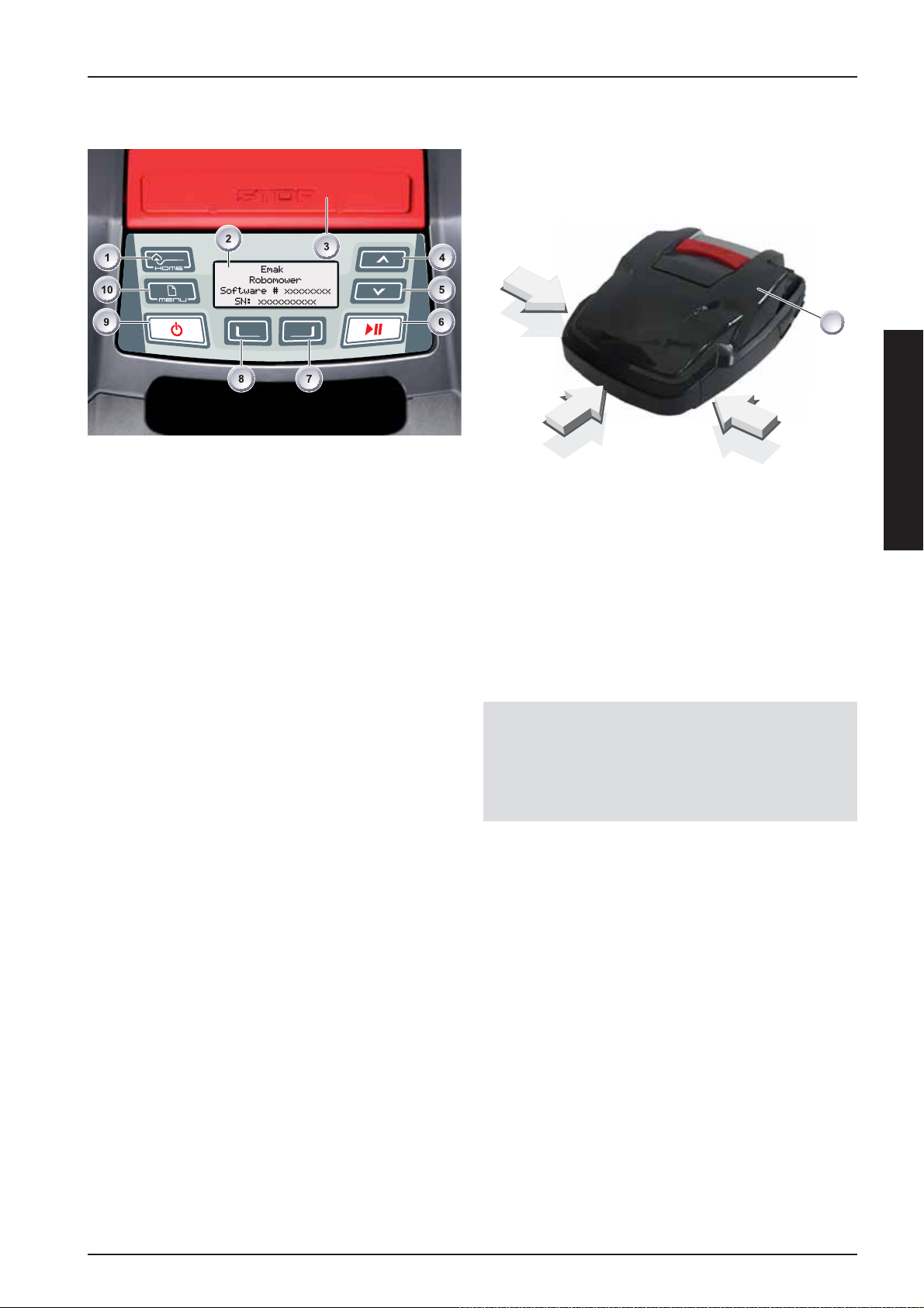
4.3 Control panel
1 HOME key 6 START/PAUSE key
2 LCD display 7 Multifunction key right
3 STOP key 8 Multifunction key left
4 Up arrow key 9 ON/OFF key
5 Down arrow key 10 Menu key
4.4 Sensors in the robot lawnmower
Bump sensors and obstacle detection
1
English
The robot lawnmower is equipped with sensors that
ensure it changes its direction of travel if it encounters
obstacles. When it encounters an obstacle, the top part of
the housing (1) is shifted slightly. This causes a sensor to
trigger a change in the direction of travel.
Function of the keys
The [HOME key] (1) cancels the current mowing
procedure. The robot lawnmower returns to the base
station and will restart with the first programmed
operation for the next day.
The [LCD display] (2) displays the current status or the
selected menu.
Pressing the [STOP key] (3) stops the robot lawnmower
and the cutting blade within 2 seconds.
The [up arrow key] (4) and [down arrow key] (5) are used
for navigating in the menu and for changing values.
Press the [START/PAUSE key] (6) to start the robot
lawnmower or interrupt operation. If you press START/
PAUSE during programmed operation the robot will
restart automatically after approximately 2 minutes.
Use the [multifunction keys right or left] (7) or (8) to
con rm or revoke commands, for example (selecting a
menu command).
If the robot lawnmower is lifted up by its carry handle
during operation, a safety sensor stops the blade within 2
seconds and switches o travel mode.
Note!
The robot lawnmower does not restart automatically after
being switched o by a safety sensor. To restart, it is necessary
to acknowledge the fault by pressing the multifunction key
and rectifying the fault.
The [ON/OFF key] (9) is used for switching the robot
lawnmower on or o .
Press the [menu key] (10) to open the menu.
51
Page 14

Travel direction anti-tipping sensor
> 35 %
4.5 Base station
4
3
0 - 35 cm
100 cm
The robot lawnmower is switched o by the tilt sensor if
it encounters an upward or downward slope of more than
35%.
Sideways anti-tipping sensor
>35 %
The robot lawnmower is switched o by the tilt sensor if it
encounters sideways slopes of more than 35%.
12
The base station (2) is connected to the electrical power
supply (transformer) using the low-voltage cable (1).
The base station (2) generates a control signal and sends
this in the boundary cable (3).
There are two charging contacts (2) on the base station
(4) which contact the charging contacts on the robot
lawnmower as soon as it moves into the base station (2).
4.6 Transformer
Important
Damage due to splash water
Set up the transformer in a dry place where it is
protected against splash water.
52
4.7 Boundary cable
Important
Damage to the boundary cable
Do not scarify the lawn in the area on either side
of where the boundary cable is laid.
The boundary cable is secured with lawn pegs. If the
supplied boundary cable is not large enough for your lawn,
you can obtain an extension cable from your dealer.
Page 15

5 Assembly/installation
5.1 Assembling the base station
2
1
2
3
1
Insert the base plate (3) with its front edge in the direction of arrow 1 into the plate of the base station (2), and fold upwards in
the direction of arrow 2. Secure the base station to the ground with the pegs (1).
English
5.2 Setting up the base station
min. 20 cm
min. 35 cm
min. 1 m
min. 1 m
1
2
Place the base station in a shady location in the garden on smooth level ground where it will be protected against the rain.
Then use lawn pegs to secure it in place (white dots). Comply with the speci ed dimensions when doing this.
Remove the insulation from the boundary cable (2) and connect it to one side (1) of the base station. Then continue to lay
the cable as shown, complying with the speci ed distances.
To avoid damage when mowing, make sure that the boundary cable (2) is in direct contact with the ground at all points
when you are laying it. If there are places where the boundary cable (2) is not in direct contact with the ground, secure
these with an additional lawn peg.
53
Page 16

5.3 Laying the boundary cable
Important!
Danger of damage to the boundary cable
and impairment of function of the robot
lawnmower!
To ensure reliable function, the boundary cable
must be laid as described in the following steps:
Check the area to be mown.
Remove mole hills and windfall fruit, and
level out any holes in the area to be mown.
Lay your boundary cable around obstacles.
Lawns with grass more than 8 cm tall
cannot be mown using the robot
lawnmower, and will have to be mown in
advance before the boundary cable is laid.
Once the boundary cable has been laid on
the grass, do not scarify the area of the
boundary cable any longer.
Spare loops of cable
ca. 1 - 2 m
You should incorporate spare loops of cable at regular
intervals in order to allow the base station to be
repositioned or the mowing area to be extended even after
the mowing area has been laid out. To do this, guide the
boundary cable around a lawn peg, return to the previous
lawn peg, then continue as shown, securing with another
lawn peg.
Laying options
1
2
max. 5/7 cm
The boundary cable can be laid on the lawn (1) and as
much as 5/7 cm under the turf (2). Have your dealer carry
out the laying under the turf on your behalf.
If necessary, you can also combine both methods.
Select the number of spare cable loops according to your
own judgement.
54
Page 17

5.4 Laying options
min. 15 cmmin. 15 cm
English
min. 30 cm
When laying the boundary cable in walkways, it is necessary to maintain the minimum distances from obstacles and the
minimum passage width, otherwise the robot lawnmower will not be able to operate correctly.
STOP
If there is a crossover in the boundary cable layout this will cause operating faults because the system will be unable to
distinguish between the internal and external sides of the boundary.
55
Page 18

5.5 Laying the cable around obstacles
When laying the cable around obstacles, maintain the
distances shown in the illustration.
5.6 Connecting the boundary cable to the
base station
min. 30 cm
min. 30 cm
When the distance is at least 30 cm, the robot lawnmower
interprets the distance as a path and moves around the
obstacle.
Note!
If there is a distance of 0 cm between the cables, it is
possible for the cable to be driven over.
1 2
Remove the insulation from the boundary cable (2) after
laying the cable and connect to the spring terminals (1).
5.7 Connecting the low-voltage cables to the
transformer
1
2
4
3
56
min. 30 cm
0 cm
Strip 10 mm of insulation o the low-voltage cables (3) and
(4).
Unscrew the screws with a screwdriver (2) and connect the
low-voltage cables (3) and (4) to the transformer (1).
The cables can be connected to either terminal, there is no
need to observe a particular polarity.
Insert the mains plug of the transformer into the mains
socket.
Page 19

5.8 Opening the cover on the rear of the
base station
Note!
The cover only has to be opened for the purpose of
checking the LED displays.
1
2
5.9 Checking the connection
21
English
Important!
Damage to the cables.
3
To check the connection, unscrew the fastening screws (3)
and remove the cover (2) from the base station (1).
The LEDs must light up when the cables are
connected. If this is not the case, pull out the
mains plug and check if all plug connections and
cables are correctly seated; also check them for
damage.
The yellow LED (1):
lights up if the base station is connected to the transformer
and there is an electrical power supply to the transformer.
ashes when the robot lawnmower is charging.
The green LED (2):
lights up when the boundary cable is laid correctly and the
loop is OK.
The green LED ashes and then goes out if the loop of the
boundary cable is not OK.
57
Page 20

6 Start-up
6.1 Preparations
Note!
Before starting to operate the robot lawnmower, place it
in its starting position in the de ned mowing area. Please
comply with the information on transporting the robot
lawnmower on 70.
ca. 1 m
6.2 Switching on/status display
Switch on the robot lawnmower by pressing the [ON/OFF
key].
The LCD display then shows the illustrated information:
Display after the status display
The LCD display shows the information Uncalibrated
min. 1 m
Comply with the speci ed dimensions.
The LCD display automatically changes to the registration
window for language selection.
6.3 Language selection
Note!
The corresponding language only needs to be selected here
during the initial start-up.
1. Use the [arrow keys] to select the required language.
2. Con rm with the [multifunction key].
58
3. After con rming, the LCD display shows [Enter registration
PIN].
Page 21

6.4 Enter PIN code
Note!
The factory-set PIN code only needs to be entered during the
initial start-up.
The factory-set PIN code is [0 0 0 0].
Entering the factory-set PIN code
6.5 Changing the PIN code
1. Enter a new PIN and repeat.
2. Con rm the last entry with [multifunction key] (3)
After this, the LCD display shows the [Date dialog box].
6.6 Setting/changing the date
English
1. Use the corresponding [arrow keys] (1) or (2) to select
the corresponding digits and con rm each one with the
[multifunction key] (3).
2. Enter the next 3 required digits in the same way.
3. Following this, the LCD display shows the [Change PIN]
dialog box.
Note!
Enter the date and time correctly, because further
programming depends on the date and time.
When entering the year (YYYY), it is only necessary to enter
the last two digits because the rst two 20XX are preset.
1. Use the corresponding [arrow keys] (1) or (2) to select
the corresponding digits and con rm each one with the
[multifunction key] (3).
After con rming, the LCD display shows [Time dialog box].
59
Page 22

6.7 Setting/changing the time
1. Use the corresponding [arrow keys] (1) or (2) to select
the corresponding digits and con rm each one with the
[multifunction key] (3).
Following this, the LCD display shows the [Uncalibrated] status
box.
Calibration procedure starts
6.8 Calibration
Note!
For calibration, set up the robot lawnmower accordingly, see
page 58 .
Warning!
The drive starts when the [START key] is
pressed.
Do not reach into rotating parts.
1. The automatic calibration procedure starts when the
[START key] is pressed.
The robot lawnmower first moves straight over the
boundary cable in order to gauge the signal strength,
and then into the base station.
Note!
The robot lawnmower must remain stopped when it moves
into the base station. If the robot lawnmower does not meet
the contacts when it moves into the base station, it will move
further along the boundary cable until it meets the contacts
or the procedure is cancelled.
The battery of the robot lawnmower is charged.
The [Drive starting] warning ashes on the LCD display.
60
Page 23

Display after the calibration movement
6.9 Starting the robot lawnmower
After calibration has been completed, the robot
lawnmower can be used for mowing with the factory-set
mowing times without further programming.
The mowing program is active, the battery is charged.
The following mowing times are factory-set:
Mon - Fri: 07:00 - 10:00 and Mon - Fri: 17:00 - 19:00
WARNING!
National regulations may place limits on
the use of the machine. Comply with any
local bylaws imposing noise restrictions during
certain hours of the day.
Checking the cable laying
Switch on the robot lawnmower by pressing the [ON/OFF
key].
Enter PIN code
English
The PIN code must be entered at this point.
ca. 1 m
1. Place the robot lawnmower about 1 metre in front of the
boundary cable.
2. Press the [HOME key], the robot lawnmower moves along
the boundary cable back towards the base station.
3. In case of collisions or if the boundary cable is laid too
close, the robot lawnmower will cancel its movement.
4. Rectify the error, place the robot lawnmower about 1 m
in front of the boundary cable once again and press the
[HOME key] a second time.
Note!
Pressing the [HOME key] deactivates the mowing day.
Pressing the [START key] activates the mowing day and
starts the mowing procedure.
Display next mowing
After the PIN code has been entered, the [Next mowing]
information appears. The robot lawnmower is now ready
for mowing.
The robot lawnmower starts automatically when the next
mowing window is reached.
Press the [START/PAUSE key] to start the mowing procedure
immediately.
The [Warning drive starting] display ashes and a signal
sounds.
61
Page 24

7 Mowing
Note!
7.1 Mowing tips
Note!
To allow the performance of the robot lawnmower to
be exploited to the full, we recommend having the
robot lawnmower mow the lawn during cool times of
the day or at night.
WARNING!
National regulations may place limits on
the use of the machine. Comply with any
local bylaws imposing noise restrictions during
certain hours of the day.
Cutting height at a constant 3 - 6 cm, do not mow o more
than half of the lawn height.
Adjust the mowing times accordingly.
If the motor speed drops noticeably because of thick grass,
increase the cutting height and mow in several passes.
7.2 Setting the cutting height
The cutting height varies in the range from
3 - 6 cm lawn height.
The cutting height can be adjusted in five steps
of 6mm each.
1. Open lever (2) and turn it a quarter turn clockwise in the
direction of [lock symbol opened] (1) (see also the quick
info).
The cutting height adjustment is unlocked.
Pull lever (2) upwards: Lawn cutting height is increased.
Push lever (2) downwards: Lawn cutting height is
reduced.
After cutting height adjustment:
Turn lever (2) a quarter turn anticlockwise in the
direction of [lock symbol closed] (1) and engage.
2. Cutting height adjustment is locked.
3. Fold lever (2) down and close the cover.
1
2
1. Press item (1). Cover (2) is unlocked and can be opened
upwards.
1
7.3 Charging the battery in the robot lawnmower
Note!
The integrated battery is partially charged on delivery.
A lengthy charging period is not necessary, because
the robot lawnmower can mow even when the battery
is partially charged.
When the charge level falls to 0% the robot
lawnmower will automatically return to the base
station to charge the battery.
Interrupting charging does not damage the battery.
The temperature range for charging should be
between 0 and 40 °C.
The built in protection circuit prevents the battery
from being charged at temperatures above 45 °C, in
order to prevent irreparable damage to the battery.
If the operating time of the battery is reduced in spite
of it being fully charged, have the battery replaced by
a new genuine battery. This task should be carried out
by an Authorised Service Centre.
62
2
Recommendation: Place the base station in a shady
location.
Page 25

7.4 Exhaustively discharged battery
If the battery charge level has dropped below the
threshold set by the manufacturer as a result of ageing or
excessively long storage, this means it cannot be recharged
any longer.
Have the battery and the monitoring electronic control
unit checked by an Authorised Service Centre, and renew it
1
if necessary.
Warning!
Do not attempt to carry out any kind of work
on the battery.
The battery status is shown on the display (1).
Make sure the charging contacts of the base station have
adequate contact with the contact surfaces on the robot
lawnmower.
Warning!
Store the robot lawnmower indoors
during the winter.
During normal operation, the battery of the robot
lawnmower is regularly recharged.
The base station is equipped with an electronic control unit
with a monitoring function. This automatically terminates
the charging procedure when a 100% charge status is
reached.
Before putting the robot lawnmower into storage for the
winter, please make sure it is fully charged.
After 3 months of storage check the battery status; switch
on the robot lawnmower and read the battery charge level.
If necessary, place it in the base station for charging.
English
Once the battery is fully recharged, put the robot
lawnmower back into store.
63
Page 26

8 Programming
8.1 Starting the robot lawnmower
Note!
Selecting the menu
In order to access the program menus of the robot
lawnmower, it is necessary to perform this start procedure in
all cases.
If necessary, switch on the robot lawnmower by pressing
the [ON/OFF key] (1), then enter the PIN code.
After switch-on, information is given regarding the next
mowing.
Note!
The displayed mowing operation may be the factory
setting, unless a new mowing operation has already been
programmed.
1
After switching on, it is possible to call up the main menu
with the [menu key] (1).
Note!
The PIN code may also be the factory code if no di erent
code was entered during calibration.
After the PIN code has been entered, the [Next mowing]
information appears again.
The robot lawnmower is now ready for the programs and
settings to be selected.
64
Page 27

8.2 Overview
The main menu of the robot lawnmower is divided up into the following submenus:
Program menu.
Setting menu.
Information menu.
English
Note!
Start the robot lawnmower as described.
Use the [up arrow key] or the [down arrow key] to select the required main menu.
The star symbol to the left of the menu displays shows which selection is active.
Con rm the required main menu with the [multifunction key right]. The corresponding sub-menus open.
Con rm the required application with the [multifunction key right]. Change the sub-menu items if required.
Use the [multifunction key left] to return to the standard display.
65
Page 28

9 Program menu
Note!
Description of function keys, see page 43.
Make the settings in the week program.
Look at the program info, e.g. mowing program.
Selecting the program
Before programming, it is necessary to perform the start
procedure, see page 64 .
Mowing time setting in batch mode
1. Select the required menu item, [Every day], with the [arrow
keys] and con rm with the [multifunction key right].
2. Press the [down arrow key] until [Change] is active.
1. Use the [up arrow key] or the [down arrow key] to select
the Programs menu item.
2. Con rm with the [multifunction key right].
3 Select the required programs and confirm with the
[multifunction key right].
The symbol [X] shows the currently active day of the week.
9.1 Setting the week program
1 In the week program, the days of the week (2) and the
times are set when the robot lawnmower should mow
automatically.
2 In the [All days] menu item (1), the robot lawnmower
mows at the set times every day.
3 Observe the mowing result and mow as long as necessary
in order to obtain a well kept lawn.
4. Use the corresponding [arrow keys] to select the required
menu point and con rm with the [multifunction key right]
in each case.
1. Select the required menu item with the [arrow keys] and
con rm with the [multifunction key right].
Explanation of symbols:
(3) [-] Mowing window deactivated.
(3) [R] Edge mowing.
The robot lawnmower mows left and right along the
boundary cable. After mowing the edges, the robot
lawnmower continues mowing the marked-out area
[M] Normal mowing
The robot lawnmower mows the entire area marked out
by the boundary cable
(4) Start time
The robot lawnmower departs from the base station at
the selected time for mowing.
(5) End time
The robot lawnmower moves back to the base station at
the selected time.
(6) [0 - 9] Fixed entry point
The robot lawnmower departs from the selected entry
point at the selected time for mowing. The start points
are set automatically and cannot be modi ed.
[?] Automatic entry point
The start points are set automatically and cannot be
modi ed.
66
Page 29

10 Setting menu
The time is displayed in 24-hour format.
Set the time.
Set the date.
Set the language.
Changing the PIN code
Set the button tones.
Activate or deactivate the margin movving.
Set the display contrast.
Reset calibration.
Restore factory settings
10.1 Setting the time
Selecting the program
Before programming, it is necessary to perform the start
procedure (see page 64 ).
1. Select the required time with the [arrow keys] and con rm
with the [multifunction key right].
Exit setup mode by pressing the [Menu key] twice.
10.2 Setting the date
Selecting the program
Before programming, it is necessary to perform the start
procedure (see page 64).
English
1. Select the required program item with the [arrow keys] and
con rm with the [multifunction key right].
2. Call up the [Date] menu.
1. Use the [up arrow key] or the [down arrow key] to select
the [Settings] menu item.
2. Call up the [Time] menu.
3. Con rm with the [multifunction key right].
Note!
When setting the time, it is necessary to select each
individual digit until it ashes.
Enter the time correctly, because further programming
depends on the time.
Con rm individual digits and use the arrow keys to select
the next digit.
Setting the date
Note!
Enter the date correctly, because further programming
depends on the date.
When entering the year (YYYY), it is only necessary to enter
the last two digits because the rst two 20XX are preset.
The date display is structured as follows:
DD for the day.
MM for the month.
YYYY for the year.
67
Page 30

1. Press the [up arrow key] brie y once. A [0] ashes at the
rst place in the display, or press the [arrow key] (2) once
brie y. A [9] ashes at the rst place in the display.
10.4 Further setting possibilities
2. Either use the [down arrow key] to count down from [9] or
use the [arrow key] to count up until the required digit is
displayed.
3. Con rm with the [multifunction key right].
4. Enter the next required digits in the same way until the
date has been fully set.
5. Con rm with the [multifunction key right].
Exit setup mode by pressing the [Menu key] twice.
10.3 Setting the language
Before programming, it is necessary to perform the start
procedure (see page 64).
Note!
All other setting possibilities are always called up in the
same way.
After switching on, it is possible to call up the
corresponding program menu with the [menu key].
1. Select the [Settings] menu in the main menu.
10.5 Activate or deactivate the button tones
Before programming, it is necessary to perform the start
procedure, see page 64 .
1. Use the [up arrow key] or the [down arrow key] to select
the [Settings] menu item.
2. Call up the required menu, [Language].
3. Con rm with the [multifunction key right].
Note!
The corresponding language only needs to be selected here
during the initial start-up.
1. Use the [arrow keys] to select the required language.
2. Con rm with the [multifunction key].
1. Use the [up arrow key] or the [down arrow key] to select
the [Settings] menu item.
2. Call up the required menu, [Button tones].
3. Con rm with the [multifunction key right].
4 Activate or deactivate the button tones with the
[multifunction key right].
Exit setup mode by pressing the [Menu key] twice.
3. After con rming, the LCD display shows [Enter registration
PIN].
68
Page 31

10.6 Changing the display contrast on the
LCD display
11 Information menu
1 In the Settings sub-menu, select [Display contrast].
2 Select [Display contrast] with the [arrow keys] and con rm
with the [multifunction key right].
Exit setup mode by pressing the [Menu key] twice.
10.7 Restoring factory settings
1 In the Settings sub-menu, select [Factory settings].
2 Enter the PIN code again and con rm.
Exit setup mode by pressing the [Menu key] twice.
Hardware information comprising, e.g.:
Product name.
Year of manufacture.
Number of operating hours.
Serial number.
Distance covered.
Software status with version number.
Note!
The Information menu is used for calling up various
information such as software status, hardware status
and current settings.
No settings can be made in this menu.
Selecting the program
Before programming, it is necessary to perform the start
procedure, see Starting the robot lawnmower on page 64.
English
1. Use the [up arrow key] or the [down arrow key] to select
the [Information] menu item and confirm with the
[multifunction key right].
11.1 Hardware information
1. Use the [up arrow key] or the [down arrow key] to select
the [Hardware or software] menu item.
2. Con rm with the [multifunction key right].
3. Call up the corresponding hardware or software
information.
4. Use the [multifunction key left] to return to the main menu.
69
Page 32

Hardware
The unit’s identi cation data will be displayed: name,
production date, operating hours, serial number, cutting
cycles, charging cycles, charging hours and perimeter of
the boundary cable.
13 Transport
11.2 Software information
The version number of the software is displayed.
12 Program information
Total weekly mowing time.
1
When transporting within the mowing area:
1 Stop the robot lawnmower using [STOP key] (2).
2 Switch o robot lawnmower at [ON/OFF key] (1).
2
Caution!
Injuries due to the cutting blades!
The blades will come to a stop in 2 seconds!
Make sure the cutting blade plate is
pointing away from your body.
1
The total set number of mowing hours is displayed.
Times per programming, the day of the week and the time
when mowing takes place.
The total set mowing time in the week is displayed.
70
2
3 Only carry the robot lawnmower by its handle (1).
Page 33

14 Maintenance
Warning!
Injuries due to the cutting blades!
Always switch off the robot lawnmower
at the [ON/OFF key] before starting
maintenance and repair work.
Always wear working gloves when
carrying out maintenance and care
jobs on the blade system.
Disconnect the transformer of the base
station from the mains.
14.1 Check the rollers can move freely
1
English
Important!
Damage to the electrical/electronic system
by incorrect cleaning!
Do not clean the robot lawnmower with
a high-pressure cleaner or under running
water. Water penetration can cause
irreparable damage to the switch, battery
and circuit boards.
Entrust all repairs (apart from replacement of the blades) to
specialist workshops approved by the manufacturer.
The user is under obligation:
1. To bring the robot mower to the workshop after
between 100 and 200 hours operation, for:
• Check on tightness of bolts
• General check on programming and detection of
possible errors
2. To bring the robot mower to the workshop after 500
and 2500 hours operation, for:
• General check on tightness of bolts and mechanical
parts
• Check on error statistics
• Check on battery status
• Check on wheel bearings
• Inspection of blade and check for possible damage
• General inspection and cleaning
Operations to be carried out periodically by the user
1 Once a week, thoroughly clean the area around the rollers
(1) with a hand brush or cloth.
2 Check the rollers (1) can move and steer freely. If the rollers
(1) do not move freely, they must be freed up or renewed.
14.2 Checking/cleaning contacts
1
Check the contact surfaces (1) on the robot lawnmower for
contamination.
Clean the contact surfaces (1) on the robot lawnmower
with a cloth if necessary.
• Once a week, clean the robot lawnmower thoroughly
with a hand brush or a cloth, and use care spray if
necessary. Contamination can impair the function of
the machine if not removed.
• Once a week, check the cutting blades for damage.
Charring on the contact surfaces indicates a poor charging
contact.
Bend the springs on the base station outwards.
71
Page 34

14.3 Checking/cleaning the base station
1
1 Disconnect the transformer mains plug.
15 Repair
Warning!
Injuries due to the cutting blades!
Switch off the robot lawnmower at the
[ON/OFF key] before starting maintenance
and repair work.
Always wear working gloves when
carrying out maintenance and care
jobs on the blade system.
Disconnect the transformer of the base
station from the mains.
Important!
Damage due to an incorrect repair!
2 Check the contacts (1) on the base station for
contamination.
3 Clean the contacts (1) on the base station using a cloth if
necessary.
4 Push the contacts (1) towards the base station and release.
The contacts (1) must spring back into the initial position.
5 If the contacts (1) do not spring back into the initial system,
have them checked by an Authorised Service Centre, and
renewed if necessary.
14.4 Cleaning the chassis
1
2
Never repair damaged cutting attachments
by welding, straightening or modifying the
shape. This may cause parts of the cutting
tool to come off and result in serious or
fatal injuries.
15.1 Renewing the cutting blade plate
1
2
3
Thoroughly clean grass catcher (1) and guide (2) using a
hand brush or a cloth.
72
1 Place the robot lawnmower with the cutting blades (3)
pointing upwards.
2 Hold cutting blade plate (2) rmly.
3 Unscrew and remove three screws (1).
4 Pull o cutting blade plate (2) with the cutting blades (3).
5 Put on cutting blade plate (2) with the cutting blades (3).
6 Brace cutting blade plate (2) rmly.
7 Screw in and tighten new screws (1).
Page 35

Renewing the transformer fuse
16 Technical data
Warning!
Danger of re due to tting an incorrect fuse
or jumpering the fuse.
Always use a fuse with the same amp
rating.
Never jumper the fuse.
1 Disconnect the transformer mains plug.
2 Using a at-blade screwdriver, carefully press in bayonet
lock (1) at the same time as opening anticlockwise. Bayonet
1
lock (1) springs out slightly.
3 Renew the fuse and close bayonet lock (1) by turning
clockwise with the at-blade screwdriver.
English
Data robot lawnmower
Length in mm 600
Width in mm 490
Height in mm 245
Weight in kg approx. 8
Mowing system Electric with 2 cutting blades
Cutting blade motor rpm 3400
Cutting heights in mm
Cutting height adjustment 5-stage in mm 6 mm per stage
Cutting width in mm 280
Max. lawn to be mown in m
Max. slope of the lawn in % 35
Distance from boundary cable to boundary line (wall/hedge) approx. 20 cm
2
30 - 60
approx. 700
Data of base station/transformer
Base station power input voltage 230 V / 16 A / 50 Hz
Secondary voltage/current/wattage 27 V AC / 2,2 A / 60 VA
Noise emissions
Measured volume in dB(A) 63
Guaranteed volume in dB(A) 69
Battery
Voltage in V 18
Capacity in Ah 1,5
Energy in Wh 27
Maximum charging temperature in degrees Celsius 40 °C
73
Page 36

17 Help in case of malfunctions
17.1 Examples of fault messages
Note!
The battery and mowing motor in the robot
lawnmower are monitored by an electronic control
unit, which displays malfunctions and the status on
the LCD display of the robot lawnmower.
6
5
4
1
2
3
1 Time 4 Fault code
2 Fault message 5 Date
3 Actuation panel 6 Malfunction display
Note!
If this display reappears, do not continue operation.
Have the robot lawnmower checked by an Authorised
Service Centre
74
Page 37

17.2 Troubleshooting
If your robot lawnmower does not function correctly, follow the recommendations below. If the fault is not listed here or you
cannot identify it, contact an Authorised Service Centre for help with troubleshooting.
Fault messages Possible cause Measure
Low battery voltage Boundary cable defective, robot lawnmower
does not nd the base station.
Battery exhausted. The battery has exceeded its service life. Have
Charging electronic control unit defective. Have the electronic control unit checked by an
The robot lawnmower does not touch the
charging contacts.
Incorrect PIN code The wrong PIN code was entered. Enter the right PIN code. Three attempts are
Uneven mowing result. Working time of the robot lawnmower is too
short.
Check the boundary cable for interruptions,
if necessary have it tested by an Authorised
Service Centre.
the battery renewed by an Authorised Service
Centre.
Authorised Service Centre. Have the battery
renewed.
Push the robot lawnmower into the base
station and check if the charging contacts
make contact.
Have the spring mechanism or the charging
contacts checked by an Authorised Service
Centre.
Have bent or broken charging contacts
renewed by an Authorised Service Centre.
possible, after which a PUK code must be
entered.
Program longer working times.
English
The robot lawnmower
mows at the wrong time.
The robot lawnmower
vibrates.
Mowing area too large. Program longer working times.
Reduce the mowing area.
The cutting height is not correct for the length
of the grass (long grass).
The cutting blades are blunt. Renew the cutting blades and the
Grass is blocking or hampering the rotation of
the cutting blade plate or motor shaft.
The time on the robot lawnmower must be set. Set the time, see Changing the time on page
Start and finish times of mowing have been
entered wrongly.
Imbalance on the cutting blade or cutting
blade drive.
Raise the cutting height
The gradually reduce the cutting height until
reaching the required height.
corresponding screws.
Have the cutting blade resharpened by an
Authorised Service Centre and reinstall it with
new screws.
Remove the grass and make sure that the
cutting blade plate can then rotate freely.
If the cutting blade plate still does not rotate
freely, remove the cutting blade plate, clean it
and reinstall it with new screws.
60 .
Set the start and finish times again, see
Changing the time on page 66 .
Check the cutting blade and cutting blade
drive and renew if necessary.
75
Page 38

Error message
Error message Possible cause Solution
CN001: Tilt sensor • Maximum gradient exceeded
• Excessively steep slope
Robot has been picked up Place the robot on a level surface and reset the error.
Exclude the excessively steep slope from the cutting
area
CN002: Lift sensor The housing has been displaced in an
upward direction because it has been
lifted or because the mower has run
over an object.
CN005: Bumper deflected The robot has collided with an
obstacle and is unable to move clear
(collision near the base station).
CN007: No loop signal
CN017: Cal: signal weak
CN008: Loop signal weak Circuit signal is weak. • Check base station power supply.
CN010: Bad position The robot has moved outside the
CN011: Escaped robot The robot has moved outside the
CN012: Cal: no loop
CN015: Cal: outside
CN018: Cal: Impact Error during calibration, impact Remove the obstacle.
No circuit signal.
Error during calibration, circuit signal
too weak.
operating area.
operating area.
Error during calibration: the robot has
not detected the circuit.
Remove the foreign object.
Remove the obstacle
• Check base station power supply.
• Check circuit.
• Disconnect and then reconnect the transformer.
• Check boundary circuit: the cable may be buried too
deep.
• Disconnect and then reconnect the transformer.
• Return the robot to the operating area.
• Boundary cable crossover
Check laying of the boundary cable (curves, obstacles,
etc.).
• Position the robot at right angles with respect to the
boundary cable; the robot must be able to straddle
the boundary cable.
• Check base station power supply.
• Check circuit.
• Disconnect and then reconnect the transformer.
• Boundary cable crossover.
CN038: Battery Battery discharged. • Check that there are no obstacles preventing the
robot from docking at the base station.
• Check the electrical charging contacts of the base
station.
• Circuit is too long or has too many islands.
• The robot lawnmower has become stuck.
Defective boundary cable, the
robot is unable to find the base
station.
Spent battery. The battery has reached the end of its working life.
Charging circuit electronics faulty. Contact an authorized service centre to replace the
Robot does not connect with the
charging
contacts.
76
Check the boundary cable for possible breaks, if
necessary have the circuit tested by an authorized
service centre
Contact an
authorized service centre to fit a new battery
charging circuit board
• Return the robot to the base station and ensure the
charging contacts are connected.
• Have the charging contacts checked and, if necessary,
replaced by an authorized service centre
Page 39

Error message Possible cause Solution
CN099: Recov escape Error cannot be cleared automatically Clear the error manually
The robot has moved outside the
operating area
CN104: Battery over
heating
CN110: Blade motor over
heating
CN119: R-Bumper
deflected
CN120: L-Bumper
deflected
CN125: Bumper escape When reversing after colliding with an
CN128: Recov Impossible Collision with an obstacle or escape
CN129: Blocked WL Left-hand drive wheel jammed Remove obstruction
Battery overheating – battery
temperature has exceeded 60°; battery
cannot discharge
Robot lawnmower motor is
overheating, temperature > 80°C.
The robot has collided with an
obstacle and is unable to break free for
reasons of safety, e.g. collisions that
occur too close to the base station.
obstacle the robot has moved outside
the operating area.
from circuit -> reversing impossible,
the robot is unable to break free.
Return the robot lawnmower to the base station.
Electronic controller performs emergency shut-down
procedure. Do not position the robot on the base
station. Switch off the robot and allow the battery to
cool down.
Switch off the robot and allow it to cool down. If the
problem recurs have the robot checked by an
authorized service centre
Remove the obstacle and reset the error message.
The housing is jammed or the bumper is faulty; remove
the obstacle
Remove the obstacle and make sure the robot housing
is correctly positioned
English
CN130: Blocked WR Right-hand drive wheel jammed Remove obstruction
77
Page 40

17.3 Interactive help
For interactive programming help, it is possible to scan in a
QR code, e.g. using a smartphone.
To do this, it is necessary to have an app that can be
downloaded from the smartphone's manufacturer. This
service may incur charges, depending on the network
provider.
18 Warranty certi cate
This machine has been designed and manufactured using
the most modern techniques. The company guarantees
its products for a period of 24 months from the original
date of purchase.
Limited warranty
1) The warranty period starts on the date of purchase.
The manufacturer, acting through the sales and
technical assistance network, shall replace free of
charge any parts proven defective in material,
machining or manufacturing. The warranty does not
affect the purchaser’s rights as established under
legislation governing the consequences of defects in
the machine.
2) Technical personnel will undertake the necessary
repairs in the minimum time possible, compatible
with organisational needs.
3) To make any claim under the warranty, this
certificate of warranty, fully completed, bearing
the dealer’s stamp and accompanied by the
invoice or receipt showing the date of purchase,
must be displayed to the personnel authorised to
approve work.
4) The warranty shall be null and void if:
- the machine has evidently not been serviced
correctly
Following this, you will be redirected to the selected
website for the topic in question.
Customers who cannot use the QR code can access the
support address at http://www.oleo-mac.it.
Costs of using the link or the QR code depend on the
mobile phone network provider.
- the machine has been used for improper purposes
or has been modified in any way,
- non-original spare parts and accessories have been
fitted
- work has been done on the machine by
unauthorised personnel
5) The warranty does not cover consumables or parts
subject to normal wear (batteries, blades, cables,
connectors, etc…).
6) The battery warranty is limited only to manufacturing
defects during the first starting of the product.
7) The warranty does not cover work to update or
improve the machine.
8) The warranty does not cover any preparation or
servicing work required during the warranty period.
9) Damage incurred during transport must be
immediately brought to the attention of the carrier:
failure to do so shall render the warranty null and
void.
10) The warranty does not cover damage to paintwork
associated with normal wear.
11) The warranty does not cover injury or damage caused
directly or indirectly to persons or things by defects in
the machine or by periods of extended disuse of the
machine resulting from the said defects.
MODEL
SERIAL No
BOUGHT BY Mr.
Do not send! Only attach to requests for technical warranties.
78
DATE
DEALER
Page 41

19 Disposal
20 Declaration of conformity
Environmental pollution!
The robot lawnmower, its batteries and
electronic components must not be disposed
Li
of in the domestic waste at the end of their
life.
Dispose of in accordance with local
r
egulations.
In accordance with Directives 2002/95/CE, 2002/96/CE
and 2003/108/CE on the reduction of hazardous
substances in electrical and electronic equipment
(ROHS) and the disposal of waste from such
equipment (WEEE)
When the symbol depicting a crossed-out refuse bin
appears on equipment, this means that it must be
collected separately from other waste at the end of its
working life.
When the equipment is no longer serviceable,
accordingly, it should be taken by the user to a special
sorted collection centre for electrical and electronic
waste, or if purchasing a new product of similar type,
returned to the dealer on a one-for-one basis
(takeback scheme).
Proper sorted collection ensures that the discarded
equipment can be sent subsequently for eco-friendly
recycling, treatment and disposal; this helps to avoid any
possible negative impact on the environment and on
health, besides enabling the reclamation of materials
used in manufacturing the equipment.
Unauthorized dumping of waste is irresponsible, and
punishable under statutory regulations.
Note!
The battery has been tested according to the UN
handbook. Therefore, the battery is not subject to
national and international regulations governing
substances of concern, whether it is an individual part
or has been installed in the robot lawnmower.
Do not dispose of the battery unless it is discharged.
A defective or spent battery must be returned by the
user
.
WARNING! Ensur
before handing over for disposal. To avoid accidents,
remove the safety connector and the motor power
cable.
e the appliance is rendered unusable
The undersigned, Emak spa via Fermi, 4 - 42011
Bagnolo in Piano (RE) ITALY declares under its own
responsibility that the machine:
1. Category: robot lawnmower
2. Brand Oleo-Mac, Type Orion 700
3. Serial ID 652 XXX 0001 ÷ 652 XXX 9999
conforms to the requirements of Directives:
2006/42/EC - 2004/108/EC,
conforms to the provisions of the following harmonised
standards:
EN 60335-1 / IEC 60335-2-107 / EN 55014-1 / EN 55014-2 /
EN 61000-3-2 / EN 61000-3-3 / EN 61000-3-3/A1
Type of cutting device: rotary blade.
Cutting width: 28 cm
Technical Documentation deposited with Administrative
Headquarters: Technical Department
Signed in Bagnolo in Piano (RE) Italy - via Fermi, 4
Date: 01/09/2013
s.p.a.
Fausto Bellamico - President
The undersigned, Emak spa via Fermi, 4 - 42011
Bagnolo in Piano (RE) ITALY declares under its own
responsibility that the machine:
1. Category: Current transformer
2. Brand Ulmer Trasformatorenbau, Type single-phase
power supply NTEV60
conforms to the requirements of Directives: 2006/95/CE,
conforms to the provisions of the following harmonised
standards: 60335-2-29
Technical Documentation deposited with Administrative
Headquarters: Technical Department
Signed in Bagnolo in Piano (RE) Italy - via Fermi, 4
Date: 01/09/2013
s.p.a.
Fausto Bellamico - President
English
79
Page 42

ATTENZIONE! – Questo manuale deve accompagnare la macchina durante tutta la sua vita.
I
WARNING! – This owner’s manual must stay with the machine for all its life.
GB
It’s an EMAK S.p.A. trademark
42011 Bagnolo in Piano (RE) Italy
Tel. +39 0522 956611 • Fax +39 0522 951555
service@emak.it • www.efco.it
Mod. 67020006 - Set. 2013
 Loading...