

Page 1

OM 106-124 - EF 106-124
GB OPERATOR’S INSTRUCTION BOOK
D BETRIBS- UND WARTUNGSANLEITUNG
F MANUEL D’UTILISATION ET D’ENTRETIEN
I MANUALE USO E MANUTENZIONE
NL GEBRUIKS- EN ONDERHOUDSHANDLEIDING
E MANUAL DE USO Y MANTENIMIENTO
PL INSTRUKCJA OBSŁUGI I KONSERWACJI
Page 2

2
Page 3

3
GB User’s manual (TRANSLATION OF ORIGINAL INSTRUCTIONS) ........................................23
D Bedienungsanleitung
(ÜBERSETZUNG DER ORIGINALANLEITUNGEN) ..........................67
F Manuel Utilisateur
(TRADUCTION DES INSTRUCTIONS ORIGINALES) ............................ 111
I Manuale di istruzioni
(ISTRUZIONI ORIGINALI) ..............................................155
NL Gebruikershandleiding
(VERTALING VAN DE OORSPRONKELIJKE INSTRUCTIES)
....................... 199
E Manual de usuario
(TRADUCCIÓN DE LAS INSTRUCCIONES ORIGINALES) ......................243
PL Instrukcja obsługi
(TŁUMACZENIE INSTRUKCJI ORYGINALNYCH) ...............................287
Page 4

4
Page 5

5
1.2
4
2
5
6
7
1
3
8
1.3.1a
100
dB
TYPE N°: xxxxxxxxxxxxx
ENGINE: xxxxxxxxxxxxx
YEAR OF PRODUCTION: xxxx
WEIGHT: xxxkg
FABRICATION: Seco GROUPa.s., BRANCH PLANT 02
Jicin , Jungmannova 11
Czech Republic
MADEIN EUROPE
CE CONFORMITY: 2006/42/EC;2004/108/EC
2000/14/EC;2002/88/EC
L
A
F
D
B
C
F
R
E
12
o
1.3.1b
F
G
H
100
dB
()
10
5
R
I
E
EMAK spa via Fermi, 4
42011 Bagnolo in Piano (RE) ITALY
Page 6

6
3.1
1
6
5
2
4
3
3.3.1a
2
3
1
4 5
63
Page 7

7
3.3.1b
3.3.1c
3.3.1d
2
1
Page 8
8
3.3.1e
3.3.1f
3.3.2a
3
1
2
7
9
8
4
5
6
11
10
Page 9

9
3.3.2b
4
1
2
5
6
10
9
7
7
3.3.2c
1
2
Page 10
10
3.3.2d
M5 x 16
M5
3.3.2e
M5 x 16
M5
Page 11

11
3.3.2f
320
l
380
l
M5 x 16
M5
3.3.2g
M5 x 25
M5
320
l
380
l
1
1+2
1+2+3
2
2
3
3.3.2h
Page 12
12
3.3.2i
M8 x 25
3.3.2j
M5 x 12
M5
3.3.2k
1
2
3.3.2l
Page 13
13
3.4.1
1
2
4.1a
1
3
P
+
+
SenDEC
HOURS
8
2
6
7
8
9
11
10
16
17
18
19
12
13
14
4
5
15
20
Page 14
14
4.1b
21
22
4.1c
6
4
5
3
2
1
4.1d
2
1
3
4
Page 15

15
5.4.4
5.6a
1
2
5.6b
1
2
6.2.2
A
A
106: 93 mm
124: 124 mm
Page 16

16
6.3.3
1
2
6.3.6a
6.3.6b
6.3.7
B
A
1
2
3
4
Page 17

17
6.3.8
2
3
1
6.3.9a
6.3.9b
2
3
4
1
6.3.9c
5
1
A
106: 145±1 mm
124: 155±1 mm
A
Page 18

18
6.3.10a
1
6.3.10b
1
3
2
6.3.10c
5
4
5
6
7
Page 19

19
6.3.10d
6.3.11
1
2
6.3.12a
1
2
3
4
4 kP
1,5 cm
Page 20

20
6.3.12b
3
5
6
50 1
50 1
±
±
6.3.14
2
3
1
90±1
Page 21

21
6.4
11
10
2
3
4
5
6
7
8
9
1
10
10
50
50
50
50
50
50
50
50
50
50
50
50
50
Page 22

22
Page 23

23
FOREWORD
Dear customer,
thank you for purchasing this riding mower from Emak S.p.A., a company renowned both in Europe and internationally as
a manufacturer of quality machines and accessories for the maintenance of grass areas.
ABOUT THIS MANUAL
This manual should guide you through, in the most simple way possible, the safe installation, operation and maintenance of your
machine and provide information about its options and capabilities. It is therefore intended for all persons that will come into
contact with the machine during its installation, operation and maintenance.
Please carefully study the manual before doing anything with the machine. Follow the instructions contained in this user’s manual
precisely so that operating the machine is easier and that it is used optimally and has a long lifetime.
► SYMBOLS USED IN THIS USER’S MANUAL
In this user's manual you will find symbols with the following meaning:
SYMBOL MEANING
These symbols mean “ATTENTION” and “WARNING”, they inform you about things that may damage your
machine and/or cause serious injury to the user.
This symbol indicates an important instruction, property, procedure or issue, which you need to be aware of and
adhere to during assembly, operation and maintenance of the machine.
This symbol indicates useful information relating to the machine or to its accessories.
This symbol is a reference to an image in the front part of the user’s manual. It is always accompanied by the
number of the image.
This symbol is a reference to another chapter in this or another user’s manual and most often it is shown together
with the number of the chapter to which it refers.
► IMPORTANT INFORMATION
This user’s manual is an integral part of the riding mower that must be included with the mower in the event that it is sold. Therefore,
keep it for future use.
Do not put the machine into operation until you have thoroughly read all the instructions, restrictions and
recommendations contained in this user’s manual, paying particular attention to the chapter “Safety of operation”.
The illustrations and pictures contained in this user’s manual may not always correspond to reality, their purpose is the description
of the main principles of the device.
► IF YOU ARE NOT SURE
In practice, unforeseeable situations frequently arise that cannot be included and described in this user s manual. Therefore, if
you are ever unsure about a procedure or if anything is unclear or you have questions, do not hesitate to contact one authorised,
professionally-equipped service centres located all over Europe, where trained and tested experts will be ready to assist you.
Page 24

24
1 │ TECHNICAL INFORMATION
1.1 | APPLICATION
The 106 - 124 is a two-axle self-propelled riding mower designed for mowing even, maintained grass areas with a maximum
vegetation height of 10 cm, e.g. in parks, gardens and sports fields, possibly on minor slopes, on which there are no foreign
objects (fallen branches, rocks, solid items, etc.). The incline of the slope must not exceed 12° (21%).
Any use of this riding mower, which is not described in this user’s manual and which goes beyond the use here described
is considered to be in contradiction to its intended purpose or use. The manufacturer of the machine is not responsible for
damages arising from such use; the risk is borne by its user. The user is also responsible for adhering to the conditions prescribed
by the manufacturer for the operation, maintenance and repairs of this machine, which may only be used, maintained and
repaired by persons that know these conditions and have been informed about possible dangers.
Only accessories, which have been approved by the manufacturer may be connected to the machine. The use of other
accessories will result in the warranty being immediately void.
1.2 | MAIN PARTS OF THE RIDING MOWER
The 106 - 124 riding mower consists of the following basic sections:
1.2
(1) Frame with a bumper
The frame with the bumper serve as a bearing element for most of the main parts of the machine.
(2) Fairing
The fairing is a combination of plastic and metal covers which appropriately cover the engine and electrical and
mechanical components of the machine. It also includes the lights for day- and night-time lighting.
(3) Battery and fuse cover
This cover under the steering wheel enables easy access to the machine’s battery and fuses.
(4) Driver’s location
The comfortable seat enables easy access to all control elements on the machine.
(5) Grass catcher
The grass catcher consists of a tubular metal frame, lid, textile sack and a dump lever handle.
(6) Fuel tank
Enables easy refilling of fuel and verification of the fuel level.
(7) Grass ejection chute
It connects the mowing deck with the grass catcher. The grass passes through it to the grass catcher.
(8) Mowing deck
The mowing deck mows and collects the grass. It consists of a cover, main plate and two mowing blades.
Page 25

25
1.3 | PRODUCT IDENTIFICATION LABEL AND OTHER LABELS WITH SYMBOLS USED ON
THE MACHINE
► MODEL IDENTIFICATION PLATE (A)
1.3.1a
1. Machine model
2. Engine model
3. Year of production
4. Weight
5. Name and address of the manufacturer
6. EC codes used to assess the product’s compliance
7. Compliance mark of the product
8. Logo of the manufacturer
9. Guaranteed noise level according to directive 2000/14/EC
The seller will write down the serial number on the other side of the front page of this manual when handing over the machine.
► LABELS ON THE FAIRING UNDER THE SEAT (B) AND (C)
1.3.1a
Danger
Do not
touch during
operation
Before
cleaning or
repairing
the mower,
stop the
engine and
disconnect
the spark
plug lead.
Do not leave
the machine
when driving
Caution,
deflected
objects
Read the
manual
Do not mow
near other
people
Do not
take on
passengers
Mow
upwards and
downwards
(the slope),
not sideways
Keep
unauthorised
persons
at a safe
distance
12
o
Maximum
working
incline
► LABELS AT THE TRAVEL PEDAL (D):
1.3.1a
R
Tra vel i n
reverse
F
Tra vel
forward
Fast
Slow
► LABELS ON THE LEFT AND RIGHT SIDE OF THE MACHINE (E)
1.3.1a
1.3.1b
Careful
Hot surface!
Danger of
burns
Page 26

26
► LABELS ON THE MOWING DECK (F)
1.3.1a
1.3.1b
Danger
Do not step
on
Rotating
tools
100
dB
Guaranteed
noise level
► FUEL TANK PLATE (G)
1.3.1b
10
5
R
Fuel tank
capacity
► LABELS AT THE BRAKE PEDAL (H):
1.3.1b
()
Brake
► LABEL AT THE DIFFERENTIAL LOCK PEDAL (I)
1.3.1b
Differential
lock
engaged
Differential
lock
disengaged
It is strictly forbidden to remove or damage labels and symbols attached to the machine. In the event of damage or illegibility of
the label, please contact the supplier or machine manufacturer and request a replacement.
Page 27

27
1.4 | TECHNICAL PARAMETERS
BASIC PARAMETERS
UNITS
RIDING MOWER MODEL
106 124
Dimensions incl. grass catcher
(Length x Width x Height)
[cm] 242 x 106 x 116 264 x 127 x 129
Weight (without fuel, oil and driver) [kg] 271 303
Wheelbase [cm] 120
Wheel gauge
Front
[cm]
74
Rear 73
Speed forward / reverse [km/h] 9 / 4.5
Mowing height [mm] 25 – 95 25 – 90
Cutting width [cm] 102 122
Volume of the grass catcher [l]
320 / 380
(depending on type used)
Wheel
dimensions
Front
["]
16 x 6.50- 8
Rear 20 x 10-8
Fuel tank capacity [l] 13
Type of battery (capacity - voltage) ---
12V - 24 Ah / 12V - 32 Ah
(depending on type used)
Page 28

28
106
Engine
rpm±100
(min-1)
Declared emission
level of ac. pressure at
the place of operation
LpAd (dB)
EN ISO 5395-1
Guaranteed emission
level of acoustic power
L
WA
(dB)
Vibration values according to
EN ISO 5395-1 (min.s
-2
)
Aggregate value of
vibration acceleration on
the hand-arm a
hv
Value of vibration
acceleration on the all
body a
vd
BS 4155 2700 85 + 4 100 < 2.5 0.55+0.28
BS 16 Vanguard 2800 83 + 4 100 < 2.5 < 0.5
BS 18 Vanguard 2800 83 + 4 100 < 2.5 < 0.5
BS 21 Vanguard 2800 85 + 2 100 < 2.5 0.6+0.3
BS 23 Vanguard 2800 84 + 4 100 < 2.5 1.6+0.6
BS 8240 2800 84 + 2 100 2.7+1.4 1.0+0.4
BS 4175 2700 85 + 1 100 3.3+1.7 < 0.5
BS 7220 3000 83 + 2 100 6.0+2.4 0.9+0.4
K 2400 ADV V-Twin 2700 85 + 4 100 2.6+1.3 0.8+0.4
K 1600 ADV 2700 83 + 4 100 4.14+2.1 0.8+0.4
Values measured according to EN ISO 5395-1 correspond to values according to EN 836+A4
124
Engine
rpm±100
(min-1)
Declared emission
level of ac. pressure at
the place of operation
LpAd (dB)
EN ISO 5395-1
Guaranteed emission
level of acoustic power
LWA (dB)
Vibration values according to
EN ISO 5395-1 (min.s
-2
)
Aggregate value of
vibration acceleration on
the hand-arm a
hv
Value of vibration
acceleration on the all
body a
vd
BS 7220 3000 86 + 1 105 < 2,6 + 1,3 0,59 + 0,3
K 2400 ADV
V-TWIN
3000 86 + 1 105 < 2,6 + 1,3 0,59 + 0,3
Page 29

29
2 │ WORK SAFETY AND HEALTH
Riding mowers model 106 - 124 are manufactured according to valid European safety norms. The machine’s manufacturer confirms
this fact in the Statement of compliance, which is included at the end of this user’s manual ( 10).
If this machine is used properly and according to the user’s manual, it is very safe.
In the event that work safety is not adhered to and all warnings in this manual are not respected, this riding mower may
cut off hands, legs or deflect objects and so may cause serious injury or death to persons, damage or destructions of the
machine or one of its parts or accessories.
2.1 | SAFETY INSTRUCTIONS
The person primarily responsible for their own safety and the safety of others during the operation of the riding mower is its user.
The manufacturer takes no responsibility for the injury of persons or damage to the machine and ecological damage resulting from
the machine not being used and operated in accordance with all safety instructions included in this user’s manual.
2.1.1 General safety instructions
! This machine may only be driven by a person over 18 years of age that has read this user’s manual. Never allow this machine to
be operated or serviced or maintained by persons that are not competent for the respective activity.
! The user of the machine is responsible for the safety of persons in the vicinity of the working area of the machine.
! It is not permitted to perform any technical modifications to the machine and its accessories. Unauthorised modifications may
lead to hazardous work safety conditions and void the warranty.
! Adhere to all requirements relating to fire safety (
2.4).
! Do not remove safety stickers or labels from the machine.
! Do not stay in the vicinity of the machine or under it, if it is lifted and is not sufficiently secured against falling or tipping over in
the lifted position.
! The components of the grass catcher are subject to strain and may suffer damage, the function of the grass catcher may
deteriorate and contents may fall out of it. Therefore, regularly perform an inspection according to the recommendations
provided in this user s manual.
! Always turn off the mowing deck and engine and take the key out of the ignition, when:
- you are cleaning the machine
- you are removing accumulated grass from the mowing deck
- you have driven over a foreign object and it is necessary to check whether the machine has been damaged or it is necessary
to remedy the damage
- the machine is vibrating with unusual force and it is necessary to identify the cause of the vibrations
- you are repairing the engine or other moving parts (also disconnect cables from the spark plugs)
2.1.2 Clothing and protective aids of the driver
! When operating the machine, always use appropriate work attire. Never wear loose clothing and short pants.
! When operating the machine, always wear firm, closed footwear, ideally with non-slip soles. Never operate the machine when
wearing sandals or barefoot.
! Usually the noise emitted during mowing does not exceed the acoustic pressure and acoustic power values specified in this
user’s manual (
1.4). In certain cases, however, it may under certain conditions and due to the condition of the terrain exceed
the specified noise levels for a short time. Therefore, the machine manufacturer recommends the use of hearing protection
when operating the machine because stressing the hearing organ with an excessive noise level or long term effects of noise
may lead to permanent hearing damage.
2.1.3 Before using the machine
! Do not use the riding mower if it is damaged or if any of its protective elements are missing. All covers and other protective
elements must always be in their place. Therefore, do not remove or put out of operation any of the machine’s protective
elements. Regularly check that these elements are working correctly.
! Do not work with the machine after consuming alcohol, drugs or medication affecting your perception.
! Do not work with the machine if you suffer from dizziness, fainting or if you are weakened or distracted in any other way.
! Before putting the machine into operation, thoroughly learn about all the control elements and ensure that you can control them
in such a way that if necessary you can immediately stop or turn off the engine.
! Do not adjust the engine regulator or the engine speed limiter.
! Before you start working with the machine, remove from the surface of the area you will be mowing, all stones, pieces of wood,
wire, bones, fallen branches and other items, which could be deflected during the mowing process. Always use protective
gloves during this.
! Remedy all defects before further use. Before starting work, thoroughly check that the belts are tensioned, the blades are sharp
and that the area inside the mowing deck is clear.
Page 30

30
2.1.4 While operating the machine
! The machine must not be used for work on slopes that have an incline greater than 12° (21%).
! Transport of other passengers, animals or loads directly on the machine is forbidden. Transport of loads is only permitted on
trailers approved by the machine’s manufacturer.
! Even when leaving the machine for a short time, always remove the key from the ignition.
! If you are driving the machine away from the work area where you are mowing, always disengage the mowing deck and lift it to
the transport position.
! Do not mow near piles of material, holes or banks. The riding mower may suddenly roll over if the wheel goes over the edge of
a hole, trench or an edge that may collapse.
! When working, avoid mole mounds, concrete supports, tree stumps, garden bed and footpath kerbs, which must not come into
contact with the blades and so cause damage to the mowing deck and the machine’s mechanism.
! In the event of an impact into a rigid object, stop and turn off the mowing deck and engine and inspect the entire machine,
particularly the steering mechanism. If necessary perform repairs before starting up the engine again.
! Whenever possible avoid using the machine in wet grass. Reduced traction may lead to skidding.
! Avoid obstacles (e.g. sudden change in the incline of a slope, trenches, etc.) on which the machine could roll over.
! Do not attempt to maintain the stability of the machine by stepping on the ground.
! Only use the machine in daylight hours or with good artificial lighting.
! Lightning can cause serious injury or death. Do not use the machine when a storm is approaching and lightning flashes can be
seen or thunder can be heard, find safe shelter.
! Driving the machine on public roads is not permitted.
! Do not leave the engine running in closed areas. The exhaust fumes contain substances that are odourless but are fatally
poisonous.
! Do not put your hands or legs underneath the mowing deck cover. Never put any part of your body near the rotating or moving
parts of the machine. Do not attempt to use your hands or other temporary items to stop or slow down moving cutting blades!
! Do not start the engine without an exhaust pipe.
! Always pay full attention to driving and other activities performed with the machine. The most common causes of loss of control
over the machine are for example:
- Loss of wheel traction.
- Excessive speed, not adjusting speed to current conditions and terrain properties.
- Sudden braking where the wheels lock up.
- Using the machine for purposes for which is was not designed.
2.1.5 After fi nishing work with the machine
! Always maintain the machine and its accessories clean and in good technical condition.
! The rotating blades are sharp and may cause injuries. Whenever handing the blades always use protective gloves or wrap the
blades.
! Regularly check the nuts and bolts securing the blades so that they are tightened with the appropriate amount of torque
(
6.3.6).
! Pay special attention to lock nuts. After the nut is loosened a second time its locking capability is reduced and therefore it needs
to be replaced with a new one.
! Regularly inspect all components and if necessary replace those that need to be replaced based on the
manufacturer’s recommendations.
2.2 | SAFETY INSTRUCTIONS FOR WORK ON SLOPES
Slopes are the main cause of accidents, loss of control over the machine or subsequent roll-overs, which may lead to serious
injuries or death. Mowing on slopes always requires an increased level of attention. If you are not sure, or it exceeds your ability, do
not mow on slopes.
! The riding mower can be used on slopes with a maximum incline of up to 12° (21%). More information
5.5.4.
! When changing direction increased care is needed. Do not turn on a slope unless it is absolutely necessary.
! Watch out for holes, roots, uneven terrain. Uneven terrain may cause the machine to turn over. High grass may conceal hidden
obstacles. Therefore, remove all foreign objects from the area where you wish to mow in advance.
! Select such a speed so that you do not need to stop when on a hill.
! Be very careful when attaching the grass catcher or making other connections. It may lead to a reduced stability of the machine.
! Perform all movements on a slope slowly and smoothly. Do not make sudden changes to speed or direction.
! Avoid starting up or stopping on a slope. In the event that the wheels lose traction, turn off the power to the blades and drive
slowly down the hill.
! Start driving very carefully and slowly when on a slope so that the machine does not “skip”. Always reduce the machine’s driving
speed before a slope, and especially when driving down a hill lower the driving speed to minimum to take advantage of the
braking effect of the transmission.
Page 31

31
2.3 | CHILD SAFETY
If the riding mower operator is not prepared for the presence of children then a tragic accident may happen. The movement of
a riding mower attracts the attention of children. Never assume that children will remain in the location where you last saw them.
! Do not allow children without supervision in areas where you are mowing grass.
! Always be prepared - if children approach you then turn off the machine.
! Before and while reversing look behind you and at the ground.
! Never transport children, they may fall and seriously injure themselves, or they may dangerously interfere with the riding mower
controls. Never allow children to operate the machine.
! Pay increased attention in places with limited visibility (near trees, bushes, walls, etc.).
2.4 | FIRE SAFETY
When driving the riding mower it is necessary to adhere to fundamentals and regulations for work safety and fire protection relating
to work with this type of machine.
! Regularly remove flammable substances (dry grass, leaves, etc.) from the area around the exhaust, engine, battery and
anywhere, where they could come into contact with petrol or oil and subsequently catch on fire and so result in a fire on the
machine.
! Allow the riding mower engine to cool down before parking it in an enclosed location.
! Pay increased attention when working with petrol, oil and other flammable substances. These are very flammable substances,
the fumes of which are explosive. Do not smoke during this work. Never unscrew the petrol tank cap and refill with petrol while
the engine is running, if the engine is hot or if the machine is in a closed location.
! Check the petrol lines before using and do not fill the petrol all the way up to the bottleneck of the tank. The heat generated by
the engine, sun and the expansion of the fuel may lead to the petrol overflowing and a subsequent fire. For storing flammable
substances use containers designed for this purpose. Never store a canister with petrol or the machine inside a building near
any source of heat. Pay increased attention when working with the battery. The gas inside the battery is highly explosive,
therefore do not smoke in the vicinity of the battery and do not use an open flame so as to avoid serious injuries.
Page 32

32
3 │ PREPARATION FOR PUTTING INTO OPERATION
3.1 | UNPACKING AND INSPECTING THE CONTENTS
The riding mower is supplied wooden crate cover. For transportation reasons some machine assemblies are disassembled at the
production plant and it is necessary to install them before putting the machine into operation. The unpacking and preparation for
operation is performed by the seller within the scope of the pre-sale service.
Inspect immediately after delivery that the packed machine has not been damaged. In the event of damage inform the carrier. If the
complaint is not lodged in time, no potential demands can be claimed.
Check that the machine model is the same as you ordered. In the event of an irregularity do not unpack the machine and immediately
report this discrepancy to the supplier.
In the packaging you will find:
3.1
(1) Crate cover
(2) Ramps (attention – these are not included!)
(3) Steering wheel
(4) Seat
(5) Documentation (5) (packed parts list, user’s manual for the riding mower, user’s manual for the engine,
user’s manual for the battery, service log book)
(6) The grass catcher (is partially disassembled in the cardboard box, with a hitch and joining material.
► UNPACKING
1. Using a suitable tool (e.g. crowbar or hammer, etc.) remove the crating (1), take out all the individually packed assemblies and
remove all reinforcing elements and packaging materials.
2. Visually inspect the machine for damage that may have occurred during transport. Also unpack all individually packed
assemblies and inspect them. In the event of any type of damage, immediately contact the supplier and do not continue with
the installation of the machine.
3. Prepare suitable ramps (
3.1 position 2) to drive the machine from the pallet. If you do not use ramps there is a danger of
damaging parts of the machine.
4. Lift the mowing deck into the transport position by pulling the lever to the highest position (
4.2). If you do not lift the mowing
deck, there is a risk of seriously damaging it.
3.2 | DISPOSAL OF PACKAGING MATERIALS
After unpacking everything, ensure that the packaging material is properly disposed of or recycled. The disposal must
conform to relevant waste disposal laws valid in the user’s country.
Disposal may be performed by a specialised company.
3.3 | ASSEMBLY OF THE SEPARATELY PACKED ASSEMBLIES
Due to the technical nature of this task the machine is prepared for operation by the seller of your riding mower (according to the
following instructions).
Before starting the installation, remove all covering protective materials, locate the riding mower on an even surface and align the
front wheels to face forward.
Page 33

33
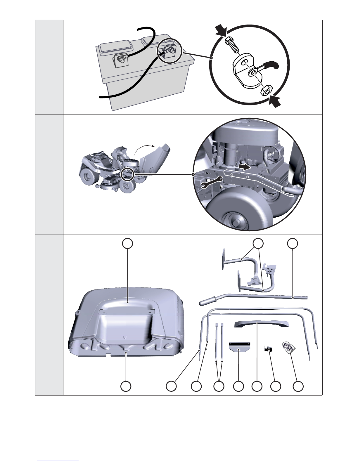
3.3.1 SEAT, STEERING WHEEL AND BATTERY
3.3.1a
a) Fit the seat sliding mechanism and the mounting bolts:
} Tilt out the seat console (1) by approximately 90
o
upwards. Into the edge of the inner hole of the console, insert
the seat sliding mechanism (2), place a plate (4) against one side of the console and bolts (3) with washers on
the other side.
} Also prepare plate (5), underlay (6) and bolts for attachment
3.3.1b
b) Attach the seat to the tilting console
} Slide the seat on to the bolts and tighten the bolts fully.
} Tilt the seat down to the working position and using the sliding mechanism lever, set the appropriate seat
position for your body size.
3.3.1c
c) Connect the cable of the safety switch:
} Connect the electric cable to the switch connector on the underside of the seat.
3.3.1d
d) Install the steering wheel:
} Seat the steering wheel on to the shaft (1) and turn it so that the holes in the steering wheel and the shaft align.
} The steering wheel has two height positions, select the appropriate height for your body size. Then insert the
supplied pin (2) into the hole and knock it in using a hammer.
3.3.1e
e) Connect the battery:
} Loosen the bolts on the pole terminals.
} Red wire Place on the (+) pole of the battery and secure in place with the bolt.
} Brown wire Place on the (-) pole of the battery and secure in place with the bolt.
- Connecting the wires in opposite to that described above will damage the machine.
- When disconnecting the battery, always disconnect the negative (–) pole of the battery first.
- When putting the battery into operation and when performing maintenance on it, proceed according to the instructions in the
user’s manual for the battery. Also follow all safety instructions contained therein.
The battery is located in the compartment under the steering wheel.
In exceptional cases, it is possible that for transportation reasons, the bumper bar of the machine is released and slides back
towards the seat. In such a case, proceed as follows:
3.3.1e
f) Fit the bumper bar in the correct position:
} Open the hood.
} Slide the bumper bar consoles away from the seat – the correct position is clearly marked on the frame.
} Properly tighten the bolts of the consoles on both sides of the machine and close the hood.
Page 34

34
3.3.2 GRASS CATCHER
The grass catcher is supplied packed in a separate box. For transportation reasons some of its parts are demounted and they first
need to be assembled. The following chapters provide a rough indication of their assembly. A detailed procedure is provided on the
CD included with the mower, or we can send it to you on request.
► NECESSARY TOOLS
For the assembly of the grass catcher, prepare the following tools:
} A knife for removing packaging materials
} A set of socket wrenches with hex heads
and hex wrenches
} Philips screwdrivers or a handheld
electric screwdriver
► UNPACKING
Remove packaging materials. First take out the lid, frame and sack and then the wrapped individual parts. Unpack these parts and
arrange them clearly in a suitable place.
► INCLUDED CONTENTS
3.3.2a
(1) Lid with top frame
(2) Sack
(3) Grass catcher hitches
(4) Dump lever handle
(5) Front tube
(6) Slanting tube
(7) Lower braces
(8) Lower hitch (for trailer)
(9) Lid handle
(10) Contact spring of full grass catcher sensor
(11) Fastening bolts, nuts and washers
A part of the grass catcher package are also spare break pins for the cutting blades (4 pcs). Keep these pins for future
use.
► GRASS CATCHER - DESCRIPTION OF THE MAIN PARTS (TERMINOLOGY)
Positions correspond to the numbers in illustration 3.3.2a.
3.3.2b
(1) Lid
(2) Sack
(4) Dump lever handle
(5) Front tube
(6) Slanting tube
(7) Lower braces (under the floor of the sack)
(9) Top Handle
(10) Contact spring of full grass catcher sensor
Page 35

35
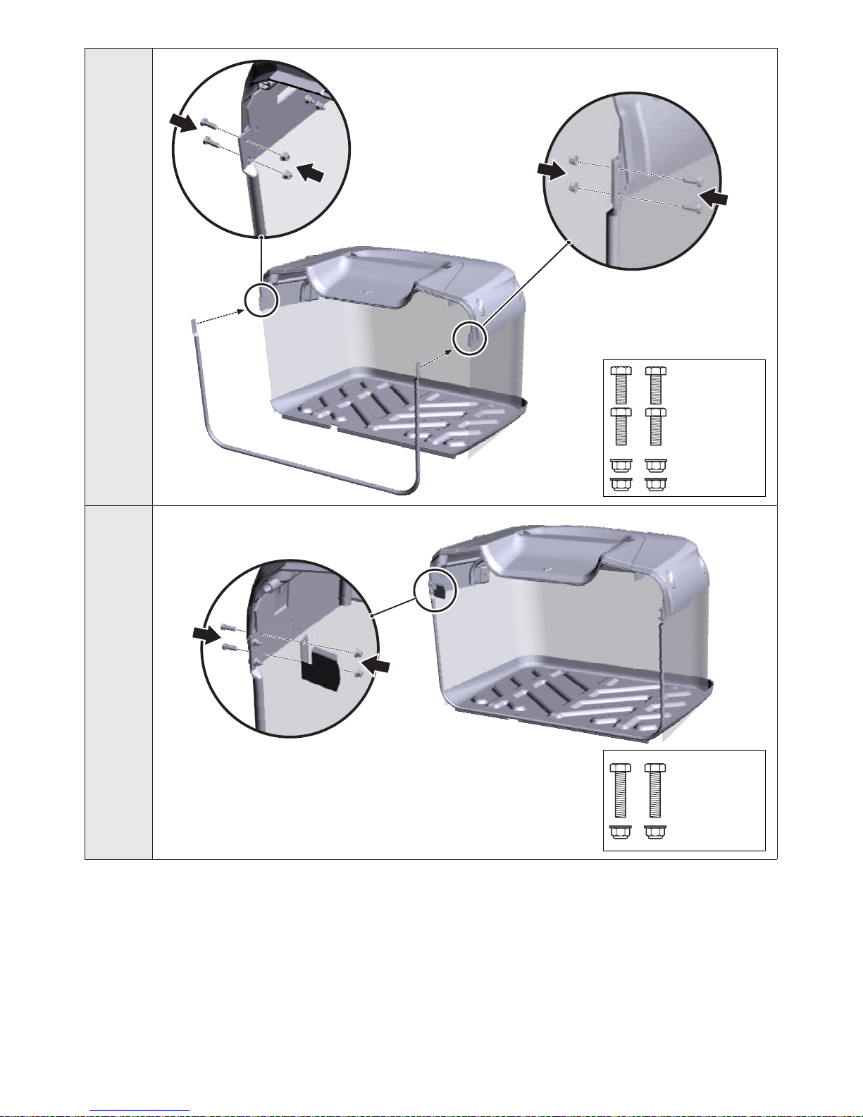
► INSTALLATION OF THE GRASS CATCHER
3.3.2c
} Screw the grass catcher hinges (1) on to the rear plate. For this purpose use the installation markings on the plate
indicating the correct position of the hitches.
} Only screw on the lower hitch (2) if you will be using a trailer (optional equipment).
3.3.2d
} Screw the front tube under the lid of the top frame.
3.3.2e
} Attach the contact spring for the full grass catcher sensor on the left side of the top frame plate.
3.3.2f
} Screw in the slanting tube into the grass catcher. For a grass catcher with a capacity of 320 l use the holes closer
to the front tube; for the grass catcher with a capacity of 380 l use the holes farther away from the front tube.
3.3.2g
} Tilt the grass catcher by 90o and from the bottom side screw on the lower braces. Attach one side of the braces to
the front tube and the second side to the slanting tube. For the 320 l grass catcher use two braces, for the 380 l
grass catcher use three braces.
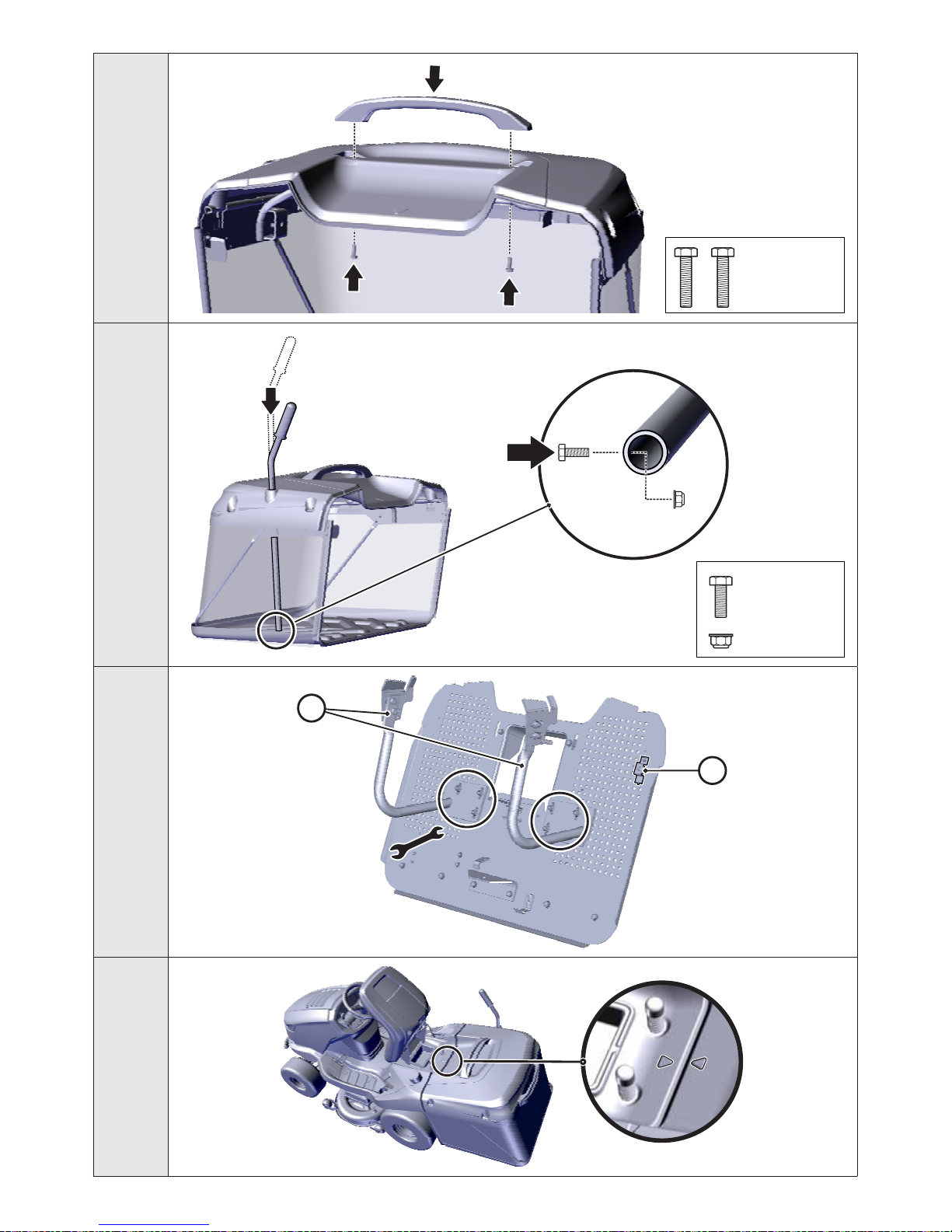
3.3.2h
} Pull the rubber edges of the sack over the front tube.
3.3.2i
} Screw the top handle to the lid and tighten the brace under the lid.
3.3.2j
} Insert the dump lever handle into the hole in the grass catcher lid.
} Into the holes in the bottom end of the lever insert a bolt from the outside and secure it in place using a nut.
► ADJUSTMENT OF THE GRASS CATCHER POSISTION AFTER INSTALLATION
3.3.2k
} Hold the grass catcher and hang it on the hitches on the rear plate of the machine.
} C
heck that the grass catcher and the mudguards match up. The arrow tips stamped on the lid of the grass catcher
and machine's fairing must point to each other while the distance between the grass catcher and the grass catcher
plate should be no more than 3 mm.
3.3.2l
} If the grass catcher is not in the correct position, loosen the bolts, holding the hitches (1) of the grass catcher to the
rear plate, set the grass catcher into the correct position and tighten the bolts.
} Also check the position of the contact spring of the full grass catcher sensor – the spring must be touching the
switch (2), otherwise the mowing deck will not function.
Page 36

36
3.4 | CHECKS PRIOR TO STARTING UP
3.4.1 CHECKING THE MOTOR OIL
The tractor must be in a horizontal position before the oil level can be checked. The oil cap is accessible after tilting open the hood.
Screw out the oil dipstick, wipe it dry, reinsert it and screw in. Then again screw it out and take the oil level reading.
3.3.2g
Oil level dipstick:
(1) - (ADD) low oil level
(2) - (FULL) maximum oil level
The oil level must be between the two marks on the dipstick. If it is not, fill up with motor oil so that it reaches the “FULL” mark. The
motor oil type is indicated in the user’s manual of the engine.
The oil level must be checked before every work session.
3.4.2 CHECKING THE BATTERY
Check the battery charge level according to the user’s manual of the battery. Respect all the manufacturer’s instructions especially
when checking and filling up the electrolyte and charging the battery.
3.4.3 FILLING THE FUEL TANK WITH FUEL
For safety reasons the riding mower is transported without fuel and before the first start up it is necessary to fill it up. Depending
on the design of the machine the fuel tank is located either under the front hood or in the left mudguard and has a fuel capacity of
14 litres.
Use only petrol with the octane number specified in the user’s manual of the engine. Defects caused by the use of incorrect fuel are
not covered by the warranty!
Only fill the fuel tank with the engine turned off and when the engine is cold. Fill up the fuel tank in a well ventilated location.
When handling fuel, do not eat, smoke or use an open flame.
For filling use a funnel designed for refilling fuel.
Respect the maximum permitted fuel tank level, i.e. the fuel level is in the lower level of the filler. Never fill up the fuel tank above
this maximum level.
Ensure that fuel is not spilled when refilling. Spilled fuel can very easily catch on fire. If fuel does spill, thoroughly wipe dry.
Store fuels out of the reach of children.
Procedure for filling up:
} Open the fuel tank cap. Open it slowly because there may be overpressure in the fuel tank caused
by petrol vapours.
} Insert a funnel into the fuel tank opening and start to pour the fuel from the canister. The fuel level
must under no condition be above the bottom level of the filler.
} After filling up the fuel tank always wipe dry the area around the fuel tank opening as well as the
fuel tank opening itself. It is good to check the condition of the fuel lines.
It is recommended to regularly also clean out the actual fuel tank because impurities found in the fuel
may cause an engine malfunction.
3.4.4 CHECKING THE AIR PRESSURE IN THE TYRES
Before putting the machine into operation, check the air pressure in the tyres.
The air pressure in the front and rear tyres must be in the range 80 - 120 kPa.
The difference between the individual tyres may be ± 10 kPa.
80 - 120
kPa
Do not exceed the maximum pressure marked on the tyres that are being used.
Page 37

37
4 │ OPERATING THE MACHINE
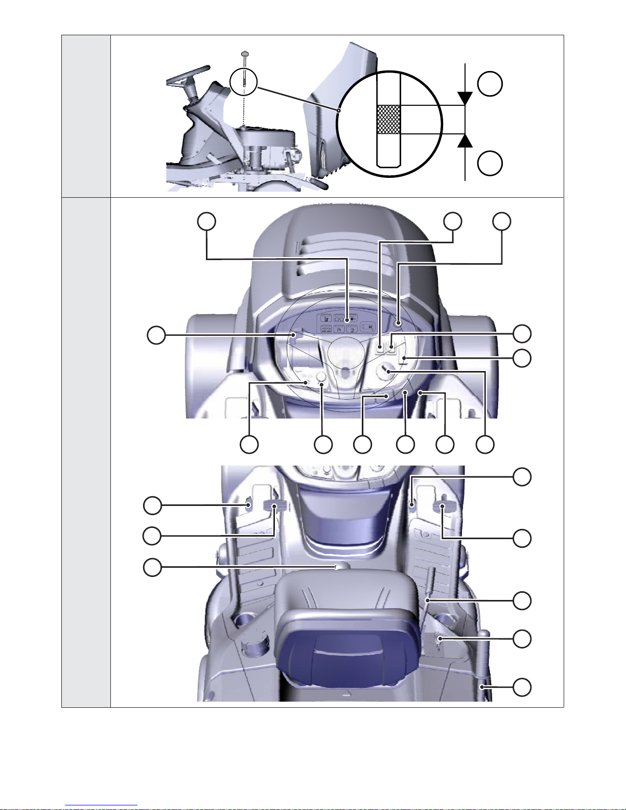
4.1 | LOCATION OF THE MAIN CONTROL ELEMENTS AND INDICATORS
4.1a
(1) Throttle lever
(2) Information panel (optional accessory)
(3) AUT/MAN switch - control of the function of mowing when the grass catcher is full (optional accessory)
(4) 12V socket (optional accessory)
(5) Deactivation of the mowing deck disengagement for reversing
(6) Mowing deck activation switch
(7) Main power switch
(8) Buzzer
(9) Parking brake
(10) Cruise control (optional accessory)
(11) Ch oke
(12) Brake pedal and parking brake indicator light
(13) Differential lock pedal
(14) Brake pedal
(15) Mulching flap lever
(16) Reverse travel pedal
(17) Forward travel pedal
(18) Mowing deck elevation adjustment lever
(19) Mowing deck position lock lever
(20) Grass catcher dump lever handle
4.1a
(21) Bypass lever for the K62 transmission
(22) Bypass lever for the K46 transmission
Page 38

38
4.2 | DESCRIPTION AND FUNCTIONS OF THE CONTROL ELEMENTS
(1) THROTTLE LEVER
Serves to regulate the engine speed. It has the following three positions:
CHOKE* Starting a cold engine
MAX Maximum engine speed
MIN Minimum engine speed (idle)
* Only on machines with a BS15, BS17, K1600 and K2400 engines
(2) INFORMATION PANEL (optional accessory)
The information panel contains indicator lights, that serve to signal the status of the machine’s basic functions.
P
+
+
Indicator light for the presence and full level of the grass catcher
It is lit: the grass catcher is not mounted on the machine
It is flashing: the grass catcher is full of grass
Motor oil pressure
When oil pressure in the engine falls, the indicator light is lit red
P
Park brake and driving brake
When the brake pedal is pushed or the hand brake engaged, the indicator light
is lit red
+
+
Charging the battery*
The colour of the indicator light changes depending on the battery voltage. It
can have the following states:
- permanently lit green = battery is OK (12.6 - 14 V) and is recharging
correctly
- quickly flashing red = low battery voltage (below 12.6 V)
- slowly flashing blue = battery voltage is over 14 V
Cruise control
When engaged the indicator light is lit green
Fuel reserve
When the fuel level in the tank falls below 5 l the indicator light is lit orange
SenDEC
HOURS
8
Mode
Counter of motor hours**
Displays the number of motor hours. Pressing the Mode button gradually switches between
the following maintenance functions:
TMR 1 - individual trip counter. The value is reset by holding down the Mode button for
6 seconds.
OIL CHG - oil change. The function has two oil change intervals. The first is after 5 hours
(oil change after the engine has run itself in) and is shown only once. The second is after
25 hours (standard oil change).
AIRFILTER SVC - cleaning or changing the oil filter. The interval is set to 50 hours.
Two hours before the set interval has elapsed the display will show a message lasting
10 seconds. After the interval has elapsed the display will show a message NOW. Any of the
above mentioned alarms can be reset by holding down the Mode button for 6 seconds.
* In the event that after starting the engine and running the machine at maximum rpm without the mowing deck engaged and
the lights turned on, and after approximately 1 minute of operation the colour of the indicator light does not change from red to
green, possibly blue, then this indicates a malfunction of the recharging circuit and it is necessary to seek out a professional
service centre.
** Tampering with the counter will result in the warranty becoming void – the motor hours counter is equipped with a protective
seal. In the event of a malfunction of the motor hours counter, immediately inform your service centre.
Page 39

39
(3) SWITCH FOR CONTROLLING THE FUNCTION OF MOWING WHEN THE GRASS CATCHER IS FULL (optional accessory)
The AUT/MAN switch serves to activate and deactivate the control of the mowing function (mowing deck) when the grass catcher
is full.
In the MAN position, mowing is activated permanently and when the grass catcher is full, grass clippings may accumulate in the
ejection chute. For this reason this position is intended only for short term use to complete the mowing of very small remaining
areas.
If the machine is equipped with an acoustic indicator (buzzer), then it is automatically activated when the basket is full.
In the AUT position, the mowing function is automatically deactivated when the grass catcher is full.
MAN
AUT
Position Grass catcher is full Mowing deck
AUT NO ENGAGED
AUT YES DISENGAGED
MAN NO ENGAGED
MAN YES ENGAGED
(4) 12V SOCKET (optional accessory)
The 12V socket is located on the right side of the cover under the steering wheel.
DC 12V
The socket can, for example, be used for the following tasks:
- connecting/recharging a mobile telephone
- connecting a portable flashlight
The socket cannot be used for recharging the battery
(5) DEACTIVATION OF THE MOWING DECK DISENGAGEMENT FOR REVERSING
Switch R serves to disengage the automatic mowing deck disengagement function when reversing (
5.5.1).
R
The switch needs to be pressed when the mowing deck has already been automatically
disengaged but the blades have not yet stopped rotating (approx. 4 seconds) or when the
mowing deck is started immediately before the reverse travel pedal is stepped on. Then with
every subsequent change in the travel direction from reverse to forward, the disengagement
of the mowing deck is again reactivated.
(6) MOWING DECK ENGAGEMENT SWITCH
Pulling out the engagement switch upwards engages the mowing deck. Pushing it down disengages the mowing deck.
1
0
1
ENGAGED
Engagement of the mowing deck / the mowing deck is
engaged
0
DISENGAGED
Disengagement of the mowing deck / the mowing deck
is disengaged
Page 40

40
(7) MAIN POWER SWITCH
Serves to start up / shut off the engine. It has the following 4 positions:
STOP
STOP
Ignition off / turn off the ignition
Turn on / turn off the headlights on the hood
Ignition on, the engine is running.
Start engine – starting position
(8) BUZZER
The buzzer makes a sound signal when the grass catcher is full
After the sound signal indicating a full grass catcher, the mowing deck is not disengaged!
(9) PARKING BRAKE LEVER
P
()
The parking brake has two positions. In the pushed in position the brake is not engaged,
after pulling it up while stepping down on brake pedal the parking brake is engaged (will
brake).
Stepping on the brake pedal will disengage the parking brake and the lever will automatically
be released and shift to the pushed in position.
If the lever is in the braking position, never push it down by hand. Always step on the brake pedal
(10) CRUISE CONTROL
Cruise control is only used when travelling in a long straight line. Before any change in direction it is necessary to deactivate the
cruise control.
1
0
Cruise control is active only when the ignition is turned on.
Engaging cruise control:
1. Set the speed by stepping on the forward travel pedal.
2. Pull out the cruise control upwards.
Disengaging cruise control:
Step on the brake pedal or the forward travel pedal.
(11) CHOKE
Enables the starting of a cold engine.
Machines with 2V (V TWIN) engines are not equipped with an separate choke.
Page 41

41
(12) BRAKE PEDAL AND PARKING BRAKE INDICATOR LIGHT
The indicator light serves to signal correct and incorrect starting of the engine (
5.2), pushed down brake and engagement of the
parking brake.
P
(())
P
()
Parking brake engaged signal
()
Brake pedal applied signal
(13) DIFFERENTIAL LOCK PEDAL
The pedal is used only if necessary and only when driving directly forward.
When the pedal is pushed down the lock is engaged.
When the pedal is released the lock is automatically disengaged.
Never use the differential lock when changing travel direction. Otherwise there is a risk of serious damage to the
transmission!
(14) BRAKE PEDAL
Stepping on the brake pedal will slow down the riding mower.
The pedal is also used when starting the machine – it is only possible to start up with the
brake pedal applied.
(15) MULCHING FLAP LEVER
The lever has two functions:
1) Mulching – grass clippings are spread out under the lawnmower
2) Grass collection – grass clippings are collected in the grass catcher
Prior to shifting the lever from the grass collection position to the mulching position (down), first stop the machine and allow the
mowing deck to run approximately 20 seconds without the mowing function so that remaining glass clippings are blown out the
ejection chute. Only then shift the lever to the mulching position and start travelling forward. Not adhering to this procedure may
cause the incorrect function of the flap and the clogging of the ejection chute.
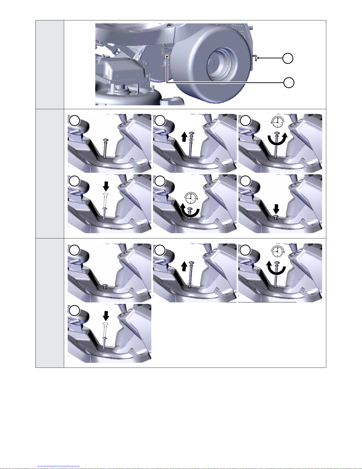
} SETTING THE MULCHING LEVER
4.1c
(1) Default state
(2) Slide the lever upwards
(3) Turn it left (anticlockwise). The telescopic draw bar will be locked in place.
(4) Push the lever downwards
(5) Turn it right (clockwise)
(6) The lever will slide down to the correct position on its own
} SETTING THE GRASS COLLECTION LEVER
4.1d
(1) Default state
(2) Slide the lever upwards. The flap will be locked in the position for collection of clippings in the grass catcher.
(3) Turn it right (clockwise)
(4) The lever will slide down to a position not interfering with work on its own
To ensure the correct function of the mulching flap, it is necessary to thoroughly clean out grass clippings and dirt from
the mowing deck and the ejection chute at the end of the mowing session.
Page 42

42
(16) REVERSE TRAVEL PEDAL
The pedal controls the power going to the wheels and regulates the speed of the machine backwards.
The more the pedal is pushed towards the floor, the faster the machine will be and vice
versa.
When the pedal is released it will automatically return to the neutral position and the machine
will stop.
More information
5.5.
Changing the travel direction forwards / reverse is only possible after stopping the machine!
(17) FORWARD TRAVEL PEDAL
The pedal controls the power going to the wheels and regulates the speed of the machine forward.
The more the pedal is pushed towards the floor, the faster the machine will be and vice
versa.
When the pedal is released it will automatically return to the neutral position and the machine
will stop.
More information
5.5.
Changing the travel direction forwards / reverse is only possible after stopping the machine!
(18) MOWING DECK ELEVATION ADJUSTMENT LEVER
The lever serves to set the elevation height of the mowing deck from the ground.
The lever has 7 work positions, which correspond to a mowing height of 3 to 9.5 cm.
The higher the number of the lever position, the higher vegetation height remains after
mowing.
When travelling without mowing, the lever must be set to position 7.
(19) MOWING DECK POSITION LOCK LEVER
The lever serves to lock the position of the mowing deck.
The lever can be used for the first four mowing deck positions. First tilt out the lock lever
upwards, then set the mowing deck lever to the appropriate position and lock this position by
tilting the lock lever downwards.
(20) GRASS CATCHER DUMP LEVER HANDLE
The lever serves to empty the grass catcher.
More information 5.6.
Page 43

43
(21) AND (22) BY-PASS LEVER – FREE MOVEMENT OF THE REAR WHEELS
The by-pass lever serves to disengage the transmission for the rear wheel drive and is used to push or pull the machine without
using the engine. Depending on the type of transmission used, it is located either behind the rear left wheel or in front of the rear
left wheel. It has the following two positions:
1
0
Position Rear wheel drive Use
[0] DISENGAGED
When pushing the machine, the engine is
still
[1] ENGAGED When driving, the engine is running
Page 44

44
5 │ OPERATION AND HANDLING OF THE MACHINE
Information which it is good to know before the riding mower is first turned on:
} The riding mower is equipped with safety contacts, which are engaged by:
- a switch located under the seat
- a switch on an attached grass catcher or deflector
- a full grass catcher switch
- a brake pedal switch
} The engine will automatically shut off when the driver leaves the seat and the machine is not secured using the
parking brake.
} The engine can only be started when the mowing deck is turned off and the grass catcher is attached, or a deflector
which during mulching prevents grass clippings from entering the exhaust chute that leads to the grass catcher is
attached and the brake pedal is applied.
5.1 | CHECKS PRIOR TO STARTING UP THE MACHINE
Before starting up the riding mower check the following:
} Oil level in the engine (
3.4.1)
} Battery charge level (
3.4.2)
} Fuel level (
3.4.3)
} Air pressure in the tyres (
3.4.4)
} That the by-pass lever is in position “1”
5.2 | STARTING UP THE ENGINE
The machine is equipped with a function that prevents the motor from starting if the following safety conditions are not met:
} The drive of the mowing deck is disengaged
} The travel pedal is not pushed down
} The driver is sitting on the seat of the machine
} The brake pedal is pushed down or the brake is engaged in the parking position
STOP
OK
NO OK
P
P
(
(
)
)
Meeting these conditions at the instant the motor is being started is
indicated by the red brake pedal and parking pedal light being permanently
lit
P
(
(
)
)
.
Not meeting these conditions at the instant the motor is being started is
indicated by the red brake pedal and parking pedal light being intermittently
lit (flashing)
P
(
(
)
)
.
After meeting the described conditions, start the engine as follows:
1) Apply the brake pedal.
2) Set the mowing deck elevation adjustment lever to position. “7”.
3) On machines with a single cylinder engine
(machines with BS15 with a power output of 15.5 HP) open the fuel supply tap. The
tap is located under the hood ( manual of the engine manufacturer)
4) Set the throttle lever as follows:
- On machines with a "NO CHOKE" engine to position “MAX”
- On machines with a "CHOKE" engine to position “CHOKE”
5) Pull out the choke (only on machines with 2V (V TWIN) engines)
6) Start up the engine by moving the ignition key to position “Start engine”. After starting the engine, release the key.
The key will
automatically return to the position “Ignition on”
As soon as the engine starts up, release the ignition key. The duration of starting up must not exceed 10 seconds, otherwise
there is danger of damage to the switch!
Never use fixed external starters to start the machine. This could damage the electrical wiring. It is possible to connect a higher
capacity 12V battery.
7) Push in the choke (only on machines with a two-cylinder engine)
Page 45

45
8) Slowly move the throttle lever to position “MIN”
Allow the engine to run several minutes before turning on the mowing deck.
Never leave a started engine running in a closed or poorly ventilated area. Exhaust fumes contain gases that are harmful to your
health.
Keep your hands, legs and clothing away from moving parts and the exhaust.
5.2.1 EMERGENCY TRAVEL SYSTEM
The machine is equipped with a special emergency travel system that makes it possible to start the engine in an emergency and
drive the machine back in the event of some kind of malfunction of the machine's electrical system that prevents the machine from
being started after meeting all the starting conditions, see above.
Procedure for activating the emergency travel system:
} sit on the seat
} push down the brake pedal
} set the key in the switch box to position "ignition on" (electrical circuits connected)
} Press the R button 5 times
Subsequently, it is possible to start the machine and to drive to a location for transport to a service centre. It is not possible to
engage the mowing deck when in the emergency travel mode!
5.3 | TURNING OFF THE ENGINE
a) Move the throttle lever to position “MIN”.
b) If the mowing deck is activated, deactivate it by pushing down the switch.
c) Turn off the engine by moving the key to position “STOP” and take the key out of the ignition.
If the engine is overheated, allow it to run for a while at minimum speed.
Never stop the engine by merely getting off the seat, while leaving the key in the ignition in the position “ON” as this may
result in an electrical defect.
Always turn the key to the “OFF” position and remove it from the ignition. This will prevent an undesirable start up of the
machine by an unauthorised person or children.
Before turning off the ignition, lower the engine speed to slow for the event of self-ignition. Not following this instruction may
result in damage to the engine and exhaust.
Never disconnect the battery cables while the engine is running! This could damage the engine regulator.
5.3.1 LEAVING THE MACHINE WHILE THE ENGINE IS RUNNING
If you want or need to leave the machine for a while (e.g. in order to remove obstacles, etc.) and you intend to then continue
mowing, it is possible to get off and leave the engine running. This saves the machine’s battery.
Conditions for getting off the machine with the engine running:
} the mowing deck is disengaged
} the throttle control lever is in position “MIN”
} the gear is in neutral and the hand brake is activated (the brake indicator light is on)
5.4 | ENGAGING AND DISENGAGING THE MOWING DECK
5.4.1 ENGAGING THE MOWING DECK
} Move the throttle lever to position “MAX”.
} Using the mowing deck elevation adjustment lever set the position of the mowing deck and thereby the mowing height.
} Set the mowing deck activation switch to position “ACTIVATED”.
Conditions for activating the mowing deck:
- the driver is sitting in the seat of the machine
- the grass catcher, or the deflector or the exhaust chute cover is installed
- the AUT/MAN switch (optional accessory) is in position “AUT” and the grass catcher is empty
- the AUT/MAN switch (optional accessory) is in position “MAN”.
Page 46

46
5.4.2 DISENGAGING THE MOWING DECK
} Deactivate the mowing deck by pushing down the activation switch.
If the driver leaves the seat, the engine will automatically shut down and thereby the rotation of the mowing blades also.
However, never turn off the mowing deck by simply leaving the seat. If you do not move the key in the ignition from the position “ON”
to position “STOP”, then a part of the electrical installation will still be live and this may result in it being damaged. Also the motor
hours counter remains activated.
5.4.3 SETTING THE ELEVATION OF THE MOWING DECK FOR MOWING
} If you wish to set the mowing deck higher off the ground, move the mowing deck elevation adjustment lever upwards.
12 3 45 6 7
} If you wish to set the mowing deck closer to the ground, move the mowing deck elevation adjustment lever downwards.
Position “1” is used to copy the unevenness of the terrain. Do not use this height permanently as this could lead to increased wear
of parts on the mowing deck.
The mowing deck is fitted with four travel wheels, which in the event of uneven terrain lift the frame with the mowing deck and so
protect the mowing blades against damage.
5.4.4 ADJUSTMENT OF THE CONTROL FORCE OF THE MOWING DECK ELEVATION ADJUSTMENT LEVER
5.4.4
If you need to expend a great deal of physical strength to move the mowing deck elevation adjustment lever from
position to position then loosen the tension of the lever mechanism spring. The spring is located on the right side of
the machine and its correct length is 93 mm (106) - 110 mm (124) when the mowing deck elevation adjustment lever is
in position 1. Use an appropriate spanner to loosen the nut and test whether the tension suits you.
If shifting the lever is too easy, tension the spring.
5.4.5 BALANCING THE MOWING DECK
To achieve the best mowing results, the cutting deck must be correctly vertically set. The adjustment procedure is described in
chapter “6.3.7 MOWING DECK - CHECKING AND BALANCING” of this manual.
5.5 | DRIVING THE MACHINE
General warnings before driving:
} Make sure that the parking brake is disengaged. The parking brake lever must not stay in the extended position – the indicator
light is lit ( 4.2). Stepping down on the operating brake automatically disengages the parking brake.
} The by-pass lever must be set to position “1”, i.e. by-pass of the travel must be activated.
} When travelling to the mowing location, the mowing deck must be disengaged and elevated to the highest position, i.e.
the mowing deck elevation adjustment lever is in position “7”.
} When travelling over obstacles higher than 8 cm (kerbs, etc.) it is necessary to use ramps to avoid damaging the mowing
deck and the gear box.
} Avoid hard impacts of the front wheels against rigid obstacles, this may result in damage to the front axle, particularly when
the machine is travelling at a high speed.
5.5.1 TRAVELLING FORWARD / REVERSING
} Slowly move the throttle lever to position “MIN”. This will lower the engine speed.
} Slowly step on the travel pedal depending on the desired direction of travel (forward or reverse).
Caution - risk of injury if the pedal is pushed down quickly!
- Changing the direction of travel forward-reverse is possible only after stopping the machine. If the machine is not still,
there is a danger of damaging the transmission.
- Never use the travel pedal and the brake pedal at the same time – this may result in a malfunction of the transmission.
The system is equipped with an automatic mowing deck disengagement for reversing function at a speed higher than 0.3
m/s (approx. 1 km/hour).
In the event of intentional and controlled reversing with the mowing deck engaged, it is possible to disengage this safety function by
pressing the R button located next to the steering wheel (
4.2 (5)). Then with every subsequent change in the travel direction from
reverse to forward, the disengagement of the mowing deck is reactivated.
When using the disengagement of this function with the R button, pay exceptional attention to the area behind the
machine when reversing.
Page 47

47
5.5.2 STOPPING TRAVEL
The forward/reverse travel of the machine is stopped by gradually taking your foot off the travel pedal and subsequently
stepping on the brake pedal.
In the event that cruise control is engaged and the brake pedal is stepped on, it automatically moves to the neutral position. The
braking distance is shorter than 2 m.
5.5.3 TRAVELLING SPEED AND MOWING GRASS
} It generally applies that the wetter, higher and more dense the grass is, the lower the travelling speed that should be used.
When the machine is travelling at high speed or when under large load, the rotation speed of the blades is reduced, the quality of
the cut is worse and the ejection chute may become clogged. Under such conditions always set the engine to maximum power.
} If the grass is very high, it is necessary to mow it several times. First mow at maximum elevation and with narrower mowing
coverage width if necessary. The second run can then proceed at the required mowing height.
} In the event that the 110 cm mowing deck is used for mulching, it is necessary to very carefully adjust the speed to the height
of the mulched vegetation respecting the significant load that this can place on the engine in this mode! The higher the grass,
the lower the travelling speed.
} We recommend mowing in the parallel or cross direction. Covering the previous coverage of the machine increases the
effectiveness of the blades and will improve the appearance of the mowed area.
} When travelling over uneven terrain the travelling speed may fluctuate.
Recommended travelling speeds of the machine based on conditions:
Condition of vegetation Recommended speed
High, dense and wet 2 km/hour
Average conditions 3 – 5 km/hour
Low, dry vegetation < 5 km/hour
Travelling without the mowing deck engaged < 8 km/hour
5.5.4 TRAVELLING ON A SLOPE
The 106 - 124 riding mower may work on slopes with an incline of up to 12°
(21%).
When working on a slope it is necessary to adhere to the following
fundamentals:
} Pay increased attention when travelling on a slope.
} Always use a slower travelling speed.
} Only travel perpendicular to the contour, i.e. up and down. Travelling in the
direction of the contour is possible with extra attention only when turning
the machine. If at all possible, avoid travelling along the contour.
} When turning ensure that a wheel does not drive over an elevated obstacle
(rock, tree root, etc.)
} Travel slower when travelling down a slope or over obstacles. Pay special
attention when turning and turning around on slopes.
} If you stop on a slope, always use the parking brake.
Right
P
Max 12
(21 )
o
%
Wrong
When overloading the machine by travelling on slopes over 12° (21%) there is a risk of serious damage to the gear box. The
manufacturer is not responsible for damage caused in this way.
Page 48

48
5.6 | EMPTYING THE GRASS CATCHER
5.6a
The full level of the grass catcher is signalled by the full grass catcher flap. It is possible to regulated the full level of
the grass catcher by moving the sliding part of the flap (extending or shortening the arm).
(1) Sliding part extended = grass catcher filled to minimum
(2) Sliding part retracted = grass catcher filled to maximum
Procedure for emptying:
} Drive the machine to the location where you wish to empty the grass catcher. Stop the machine and apply the brake. If on
a slope, use the parking brake.
} Deactivate the mowing deck by pushing down the activation switch.
} If the AUT/MAN switch is installed on the machine, leave this switch in position “AUT”.
} Set the throttle lever to position “MIN”.
} Slide the grass catcher dump lever handle completely upwards (1) and tilt it down (2) to tip out the grass catcher,
allow it to empty freely, slowly release it and tilt it back.
5.6b
Page 49

49
6 │ MAINTENANCE AND ADJUSTMENT
Properly performed regular maintenance and inspection of the riding mower helps to increase its problem-free operating lifetime.
Worn or damaged parts must be replaced in time. When replacing parts use only original spare parts, using non-original
parts may damage the machine, endanger the health of the driver or other persons and during the warranty period it
voids the warranty. To order spare parts always contact the machine’s manufacturer or an authorised service centre.
Incorrectly performed or completely neglected maintenance may lead not only to problems with the operation of the riding mower,
but may also cause injury to its operator.
All safety and protective elements that are removed during maintenance, must always be reinstalled to their correct location and
tested for functionality.
6.1 OVERVIEW OF CHECKS AND MAINTENANCE
INTERVAL ASSEMBLY ACTIVITY
BEFORE EVERY
USE
Engine and transmission Inspection of mounting, inspection of quick coupler parts
6.2.1
6.3.16
Travel drive belt Inspection and adjustment 6.3.12
Tyres Inspection of controls 6.2.1
Pneumatiky Inspection of pressure 6.2.1
Cables Inspection of mounting, inspection of quick coupler parts 6.2.1
Bolt connections Inspection, tightening if necessary 6.2.1
Mowing deck Inspection of tension of the cogged blade drive belt 6.3.9
Safety switches and elements Inspection of function 6.2.1
AFTER FIRST 2
HOURS
Engine and transmission Check oil level 6.2.1
AFTER FIRST 5
HOURS
Engine Oil change
6.3.2
6.3.16
Travel drive belt Inspection and adjustment
4
6.3.12
Mowing deck
Inspection of tension of the cogged blade drive belt
4
6.3.9
Inspection of the correct tension of the mowing deck
drive V-belt
4
6.3.8
AFTER EVERY USE
Mowing deck
Cleaning and washing 6.2.2
Inspection of the correct tension of the mowing deck
drive V-belt
6.3.8
The entire machine Cleaning 6.2.2
Grass catcher Cleaning of the textile sack 6.2.2
Bolt connections Inspection, tightening if necessary 6.2.1
AFTER 25 HOURS
Engine Changing the oil
1,2
6.3.2
Battery Inspection of electrolyte and cleaning 6.3.1
Bolt connections Inspection, tightening if necessary 6.2.1
Travel drive belt Inspection and adjustment 6.3.12
Front axle and steering\ Inspection and adjustment of play 6.3.11
Mowing deck
Inspection of play, alignment of shafts, inspection and
sharpening of blades
3
6.3.6
6.3.7
Lubrication Lubrication of parts according to lubrication plan 6.4
Page 50

50
(continued)
INTERVAL ASSEMBLY ACTIVITY
AFTER 50 HOURS
Air filter and spark plugs Inspection, replacement if necessary
1,2
6.3.2
Lubrication Lubrication of parts according to lubrication plan 6.4
AFTER 100 HOURS
Engine, transmission,
electromagnetic transmission
Inspection and adjustment of motion N
MONTHLY
Tyres Inspection of pressure 6.2.1
Mowing deck Inspection of tension of the cogged blade drive belt 6.3.9
BEFORE THE
SEASON
Fuel filter Replacement N
Battery Inspection of electrolyte and cleaning 6.3.1
Travel drive belt Inspection and adjustment 6.3.12
Mowing deck
Inspection of tension of the cogged blade drive belt 6.3.9
Inspection of the correct tension of the mowing deck
drive V-belt
6.3.8
Front axle and steering Inspection and adjustment of play 6.3.11
AFTER THE
SEASON
(PUTTING OUT OF
OPERATION)
Engine Oil change 6.3.2
Cables Inspection of mounting, inspection of quick coupler parts 6.2.1
Mowing deck Cleaning 6.2.2
Explanations for table:
1 = Replace the oil more frequently if the riding mower is under greater load or works in outdoor temperatures around 35°C or higher.
2 = If the machine works in a dusty environment, perform the inspection more frequently.
3 = Perform the inspection more frequently if the machine works in a sandy environment.
4 = Perform the inspection more often if a new belt has been fitted.
N = Manual of the manufacturer, supplied with the machine.
6.2 | DAILY CHECKS AND MAINTENANCE
Before starting any maintenance or repair works, thoroughly reacquaint yourself with all instructions, restrictions and
recommendations in this user’s manual.
Always remove the key from the ignition and disconnect the spark plug cables before performing any cleaning, maintenance or
repairs.
When working use suitable work clothing and work footwear. Use suitable gloves when handling a mowing blade or for activities
where there is a risk of cuts.
Avoid spilling fuel, oils or other harmful substances.
Do not perform any major repairs if you do not have the necessary tools and a good knowledge about repairs of
combustion engines!
Dispose of used oil, fuel or other hazardous substances and materials in accordance environmental protection regulations in force.
6.2.1 BEFORE STARTING WORK
► INSPECTION OF TYRE PRESSURE
Maintain the prescribed tyre pressure and check it regularly. Maintaining the prescribed tyre pressure is important for even mowing.
Different pressure values may cause difficulty in driving, or even loss of control over the machine.
The air pressure in the front and rear tyres must be in the range 80 - 140 kPa, whilst the differences between individual tyres may
be ± 10 kPa.
► INSPECTION OF THE OIL LEVEL IN THE ENGINE
Park the riding mower on a horizontal surface. Open the hood and unscrew the cap of the filling opening. Screw out the oil dipstick,
wipe it dry, reinsert it and screw in. Then again screw it out and take the oil level reading.
The oil level must be between the two marks on the dipstick. If it is not, fill up with motor oil so that it reaches the “FULL” mark.
Further details about checking and fi lling of oil are included in a separate user’s manual supplied by the engine’s manufacturer.
► INSPECTION OF CABLES AND BOLT CONNECTIONS
Visually inspect the condition of cables and manually check the tightness of bolt connections.
Page 51

51
► INSPECTION OF WORKING ORDER OF BRAKES
Check that the brakes work properly. Proceed as follows:
} Park the machine on an even surface and turn off the engine.
} Step on the brake pedal and engage the parking brake.
} Using the by-pass lever disengage the rear wheel drive.
} Try to push the machine forward. If the rear wheels rotate, then the brakes need to be serviced. Contact an authorised service
centre to have them adjusted.
► INSPECTION OF THE WORKING ORDER OF SAFETY ELEMENTS
Before every use of the riding mower, check the working order of safety elements:
} switch under the seat
} switch on an attached grass catcher or deflector
} full grass catcher switch
6.2.2 AFTER FINISHING WORK
► SETTING UP THE MACHINE
After finishing mowing, elevate the mowing deck to the highest position and disable the drive for the mowing blades.
Turn off the ignition, step on the brake pedal and secure the machine in position with the parking brake. On machines, where
present, close the fuel supply.
► CLEANING THE MACHINE
Remove all dirt and grass remains from the surface of the tractor, the ejection chute and the mowing deck.
Thoroughly clean the textile sack of the grass catcher. When it is clogged with grass, the ability of the machine to fill the grass
catcher is reduced.
► WASHING THE MACHINE
Before washing, park the machine on a suitable even surface.
} Grass catcher:
- remove the grass catcher from the machine, wash it and allow it to dry naturally.
} Plastic parts on the machine:
- clean using a sponge and soapy water
} Mowing deck:
- wash the inside including the part of the ejection chute
- slide a hose of a suitable diameter on to the fittings on the mowing deck cover. Start the engine, engage the
mowing deck and flush out the mowing deck with a current of water for 10 minutes.
This flushing procedure needs to be performed at the end of every mowing session.
6.2.2
Avoid washing with water in the vicinity of electrical accessories on the control panel, battery, etc.
Do not spray pressurised water on to bearings or pulleys!
We do not recommend cleaning the machine and particularly the mowing deck using pressurised water. This can reduce the
lifetime of bearings and other moving parts!
6.3 | REGULAR CHECKS, MAINTENANCE AND ADJUSTMENT
6.3.1 BATTERY
Correct and regular maintenance of the battery will extend its lifespan. Therefore regularly check its condition according to the
manual supplied by the battery’s manufacturer.
} Keep the battery contacts clean. If dirt accumulates on them, or they are rusty, clean them according to the recommendations of
the battery’s manufacturer. Interruption of the circuit caused by the oxidation of the contacts may lead to the malfunction of the
recharging function of the engine!
} Regularly check the condition of the electrolyte. The level must be in the range MIN - MAX. In the event of
filling up the electrolyte, use only distilled water.
} A flat battery needs to be recharged as soon as possible, otherwise its cells may be irreparably damaged.
} It is always necessary to charge the battery before:
- first use
- when not planning on using it for a long time
- before starting up after a longer break
} If it is necessary to replace the battery, always use a battery of the same size and type.
Page 52

52
Further details about checking and maintaining batteries are included in a separate user’s manual supplied by the battery’s manufacturer.
6.3.2 ENGINE
► CHANGING OIL
Before changing the oil, prepare a container with a volume of at least 2 litres. So that all the oil
flows out of the engine we recommend that you place something (e.g. wooden blocks) under the
side opposite the drain screw. Drain the oil while it is still warm.
} Unscrew the filler opening of the oil so that the oil flows better and faster out of the engine.
} Clip out the drain hose from the holder on the side of the engine and screw out the plug.
} Tilt the hose towards the prepared container and allow the oil to drain completely.
} Screw the plug back on and clip the hose back in. Fill the engine with the correct amount of the
recommended oil (
User’s manual for the engine) and close the oil filler cap.
} Use the dipstick to check the correct oil level. If necessary fill up the oil so that the oil is at the
correct level.
Further details about replacing oil as well as its type and amount are included in a separate user’s manual supplied by the
engine’s manufacturer.
If you come into contact with used oil, we recommend that you thoroughly wash your hands with soap and water.
Dispose of used oil according to environment protection laws. It is appropriate to deliver the oil in a closed container to a used oil
collection point. Under no circumstances should dispose of the used oil with other waste or pour it down the drain, on to waste or
on the floor.
► MAINTENANCE OF THE AIR FILTER
Never allow the engine to run without an air filter. This rapidly wears out the engine.
Maintain the air fi lter according to the instructions contained in the user’s manual for the engine supplied by its manufacturer.
► MAINTENANCE OF THE SPARK PLUG
For the engine to run perfectly the spark plug must be correctly set and clean from deposits.
- Always use only the spark plug specified by the engine’s manufacturer!
- If the engine was running shortly before the inspection or replacement, then the spark plug will be very hot. So be very careful
not to burn yourself.
} Take off the spark plug cable and remove the spark plug using a wrench key.
} Visually inspect the exterior appearance of the spark plug. If the spark plug is visibly significantly
worn out or if the insulator is cracked or it is peeling, it is necessary to replace it.
} If the spark plug is soiled or only slightly worn, it is necessary to carefully clean it with a suitable wire
brush (copper).
} Using a gauge measure set the distance of the electrodes (
User's manual for the engine).
} After performing maintenance on or replacing the spark plug, pull it tight in position. An incorrectly
tightened spark plug heats up significantly and may cause serious damage to the engine.
0,7 - 0,8 mm
Check, maintain and replace spark plugs according to the instructions contained in the user’s manual for the engine supplied by its
manufacturer.
► REPLACEMENT OF THE FUEL FILTER
Never allow the engine to run without an air filter. This rapidly wears out the engine.
Replace the fuel filter according to the instructions contained in the user’s manual for the engine supplied by its manufacturer.
6.3.3 REPLACING LIGHT BULBS
Light bulbs are seated in a reflector and are accessible after lifting the hood. The individual types of light bulbs are as follows:
Type of light bulb: Socket/reflector: Replace with:
Halogen light bulbs 10W / 12V
Reflector M Light, type HLRG-510F,
diameter 51 mm (cap GU5.3)
M light type HSS-510
or equivalent of another manufacturer
6.3.3
} When replacing the halogen light bulbs first press the tab (1) and slide the bulb out of the socket (2). For
installation proceed in the reverse sequence.
Page 53

53
6.3.4 REPLACING A FUSE
If a fuse is damaged the engine will immediately shut off, the mowing deck will stop and all
indicator lights on the dash board will turn off. In this case it is necessary to find the faulty
fuse and replace it with a new one. Under no circumstances should you replace a faulty fuse
with a fuse that has a higher current rating!
Fuses are accessible after removing the battery cover located under the steering wheel and
removing the fuse cover.
} Remove the fuse and insert a new fuse with the same rating as the initial fuse, i.e. 15A or
10A. If even after replacing the fuse the engine or the mowing deck will not work, contact
an authorised service centre.
} Certain machine models are equipped with a central switchboard. Under no condition
should you tamper with the switchboard! The only exception is the replacement of fuses.
6.3.5 LIFTING THE MACHINE
If you wish to lift the riding mower, use a jack and supports.
Proceed as follows:
} Place the jack underneath the gear box on the rear axle and lift the rear part of the machine.
} Insert two supports underneath the ends of the axles from the inner side of the rear wheels.
} Lift the front part of the machine and insert two supports under both ends of the front wheel axles.
Never lean the machine to the side where the carburettor is located. Oil could enter the air filter!
6.3.6 MOWING DECK - SHARPENING AND REPLACING BLADES
► SHARPENING THE BLADES
The mowing blades must be sharp, statically balanced and straight. Blunt, incorrectly sharpened or damaged mowing blades
cause grass to be torn out of the ground, damage to lawns and mediocre collection of mowed grass in the grass catcher.
Do not repair a blade that is deformed or other wise damaged, replace it immediately.
Whenever handling the mowing blades, always use heavy-duty work gloves.
Sharpening procedure:
6.3.6a
} Remove the grass catcher, tilt the machine on to the right side and prop it up using suitable supports. It is
recommended to invite another person to help with tilting the machine in order to prevent damaging a part of the
machine or an injury.
} Unscrew both blades and clean them.
} First sharpen with a grinder and then with a file.
} On the 110 cm three-blade mowing deck each pair of blades is fastened using 3 bolts (blades are not equipped
with break pins). We recommend that you mark the blades before removing them to avoid problems when putting
them back.
Do not sharpen directly on the mowing deck.
} After sharpening the blades, do not install them yet, but check their balance, see procedure below.
} Prior to reinstalling the blades, check the condition of the break pins which serve as protection of the mowing deck.
If the break pins are damaged, replace them immediately. Spare pins are supplied with the machine.
6.3.6b
} After checking the balance and the brake pins, screw the blades back in position. During installation, ensure that the bend of the
blades points upwards into the mowing deck body. Do not interchange the left and right blades. The right blade has a bolt with
a left thread.
} Carefully tighten the fastening bolts using a torque wrench using the prescribed tightening torque of
30 ± 3 Nm. This torque is
achieved the moment when the tangential (convex) spring under the fastening bolt is fully compressed and from this point on the
bolt is not tightened.
► BALANCING THE BLADES
Pay increased attention to levelling and balancing the blades. The vibration of blades that are not levelled and balanced may
damage the engine or the mowing deck.
When balancing, insert the screwdriver into the centring hole and set the blade into
a horizontal position. If the blade remains in this position, it is balanced. If one of the ends
is weighs down, grind this side until it is balanced. When balancing by grinding, do not
shorten the length of the blade! The permitted static imbalance may not exceed 2g.
Page 54

54
If you are not certain about the procedure, please contact an authorised service centre, where they will gladly provide advice.
► REPLACING THE BLADES
If due to frequent use the blades are damaged, they cannot be balanced or sharpened properly, it is necessary to replace them.
Proceed as follows:
} Remove the grass catcher, tilt the machine on to the right side and prop it up using suitable supports. It is recommended to invite
another person to help with tilting the machine in order to prevent damaging a part of the machine or an injury.
} Screw out both blades.
} Prior to installing new blades, check the condition of the brake pins which serve as protection of the mowing deck. If the break
pins are damaged, replace them immediately.
} Check that the blades are balanced, see above.
} Screw on the new blades. During installation, ensure that the bend of the blades points upwards into the mowing deck body. Do
not interchange the left and right blades. The right blade has a bolt with a left thread.
} Carefully tighten the fastening bolts using a torque wrench using the prescribed tightening torque of
30 ± 3 Nm. This torque is
achieved the moment when the tangential (convex) spring under the fastening bolt is fully compressed and from this point on the
bolt is not tightened.
When the blades impact a solid obstacle, immediately stop the engine and check the blades! The break pins may be
damaged or broken.
Whenever handling the mowing blades, always use heavy-duty work gloves.
Always only use blades recommended by the manufacturer or supplier of the riding mower. The use of blades and/or
fastening parts that are not recommended may result in improper mowing results, damage to the machine and in the
event that they come off during operation also injury to people.
6.3.7 MOWING DECK - INSPECTION AND BALANCING
To achieve the best mowing results the mowing deck must be set at the correct mowing height and both sides of the deck must be
level.
Before carrying the adjustment:
} Place the machine on an optimally even surface, inflate all the tyres to the prescribed pressure (80 -140 kPa, ± 10 kPa
difference between the individual tyres) and secure the entire machine against movement (e.g. using a suitable wedge, etc.).
} Move the mowing deck elevation adjustment lever to position 1.
The mowing deck is equipped with plastic covers which prevent hand access to moving parts and to the machine drive
parts of the machine.
The covers can be very quickly and easily removed using the quick coupling pins on the sides of the covers. Slide
a screwdriver into the pin groove and turn it anticlockwise. Then take the cover off the machine.
6.3.7
} Distance A is the front edge of the mowing deck in the travel direction and it must be 23-25 mm above the ground.
Check it on both sides of the mowing deck. If the height is different, loosen the lock nuts (2) on the respective draw
rod (1) and adjust the height by the turning nuts (3). After setting the correct height, do not forget to tighten the lock
nuts (2).
} Distance B is the rear edge of the mowing deck in the travel direction and it should be 28-30 mm above the
ground, i.e. the rear edge must be at least 5 mm higher than the front edge. If the height is different, adjust it by
loosening nuts (4), setting the edge to the correct height and tightening the nuts with a torque of 55 – 65 Nm.
If you are not certain about this procedure, have it performed by a service centre.
6.3.8 MOWING DECK - CHECKING AND ADJUSTING THE V-BELT
6.3.8
Because of the demands placed on it, the tension of the mowing deck drive belt (1) declines over time and it is
necessary to tension this belt. The belt is tensioned using bolts and a spring.
} Set the mowing deck to position 1.
} Using a suitable wrench, turn nut (2) so that spring (3) is tensioned to a value of 145±1 mm (106) - 155±1 mm (124).
6.3.9 MOWING DECK - ADJUSTING THE COGGED BLADE DRIVE BELT
6.3.9a
} Lower the mowing deck to the lowest position by moving the elevation adjustment lever to position 1.
} Release the quick coupling pins of the mowing deck side covers and take the covers out.
} Release the quick coupling pin (1) of the top cover (2) and approximately in its middle tilt the cover upwards
6.3.9b
} Slide an appropriate spanner under the metal cover, from underneath place it on the belt pulley bolt (1). From
above loosen the belt pulley nut.
} Loosen the lock nut (2) and nut (3). Then, using an appropriate wrench, turn nut (3) so that the cogged belt (4) is
properly tensioned.
Page 55

55
6.3.9c
} The belt is correctly tensioned when a force of 4 kP (40 N; 72 Hz) acting on the middle distance between the belt
pulleys (1) and (5) results in the belt bending by approximately 0.5 cm.
To measure force you can use a standard mechanical dynamometer available in stores selling such products.
} Tighten the lock nut (2) of the tensioning mechanism and again tighten the nut of the cogged belt pulley (1).
} Reattach the side and top cover and tighten them.
6.3.10 MOWING DECK - REMOVING IT FROM THE MACHINE
6.3.10a
} Set the mowing deck to the highest position by moving the elevation adjustment lever to position 7.
}
Slightly lift up the grass ejection chute (1) and slide it off the two pins welded to the frame of the mowing deck.
Then either move the chute approx. 10 cm backwards and secure it in place, or completely take it out through the
rear plate.
6.3.10b
} Using an appropriate wrench, turn nut (2) so that the tension on the spring (3) is completely released. Then remove
the belt (1) from the belt pulley of the electromagnetic engine transmission.
6.3.10c
} Slide the spring pins (4) from both the rear mowing deck suspension shaft pins (5). Screw out the nut (6) from the
front shaft pin and pull out the shaft pin (7). Using pliers, slide out both pins (5). For the the mowing deck mulching
option, first remove the part of the mulching flap lever that extends above the floor of the machine.
6.3.10d
} Slowly pull out the mowing deck to one side of the machine.
6.3.11 MAINTENANCE OF STEERING
6.3.11
Regularly check that there is not excessive looseness between the cogged steering segment and the steering wheel
pinion. If higher looseness is identified, it is necessary to limit it. Procedure for limiting (adjusting) looseness:
} Lift the hood.
} Loosen two nuts M12 (1) on the bolt of the eccentric.
} Place a suitable wrench on to the hexagon of the eccentric (2) and turn it until looseness is limited to a minimum.
} Tighten both nuts M12 (1) using a torque of 35 - 45 Nm.
Neglecting this maintenance may result in damage to steering components.
6.3.12 CHECKING AND ADJUSTING THE TRAVEL DRIVE BELT
6.3.12a
Regularly check the tension of the travel drive belt. The belt is correctly tensioned when a force of 4 kP acting on the
middle distance between the belt pulleys (1) and (3) results in the belt bending by approximately 1.5 cm.
When the amount of bend increases, it is necessary to adjust the tension.
Positions in the picture are:
(1) Engine belt pulley
(2) Guide belt pulley
(3) Tensioning belt pulley
(4) Transmission belt pulley
To measure force you can use a standard mechanical dynamometer available in stores selling such products.
6.3.12b
Adjust the tension of the belt by tightening nut (6) so that the spring (5) is stretched to a length of 90±1 mm.
Do not over-tension the belt above this level, this will reduce its lifetime and may also cause damage to the transmission!
Page 56

56
6.3.13 REPLACING BELTS
Replacing drive belts is a relatively demanding operation, which needs to performed by an authorised service centre.
6.3.14 REPLACING WHEELS
Before replacing one of the wheels, park the machine on a horizontal and rigid surface, turn off the engine and remove the key from
the ignition. Perform the replacement as follows:
6.3.14
} Lift the machine using an appropriate jack on the side where you will perform the replacement. Locate the jack
under a solid part of the frame or on the arm of the transmission. Using a wooden block, secure the machine to
prevent it rolling off.
} Remove the protective cover (1) from the wheel (only the front wheels).
} Using a suitable screwdriver remove the retaining ring (2) and remove the washer (3).
When reattaching the wheel proceed in the reverse sequence to its removal. Before attaching the wheel clean all parts and lightly
grease the shaft with a plastic lubricant. Especially for wheels on the rear axle this lubrication is essential for the subsequent
removal of the wheel. In the event that lubrication is not performed the subsequent attachment may be very difficult.
When attaching the rear wheel pay attention to the mutual alignment of the pin on the shaft and the groove on the wheel.
6.3.15 REPAIRING A TYRE PUNCTURE
The machine is equipped with tubeless tyres. In the event of a puncture have it repaired at a specialised tyre repair shop or at an
authorised Seco machine service centre.
6.3.16 MAINTENANCE OF THE HYDROSTATIC TRANSMISSION
For the reliable operation of the transmission it is necessary to maintain the correct oil level. The filling openings on the
transmissions are accessible after taking the ejection chute off the machine ( 6.3.10). Prescribed values are provided in the
following table.
Type of transmission Oil type Oil level
TUFF-TORQ K46 SAE 10W-40, API CD At least to half the height of the equalisation tank
TUFF-TORQ K62 SAE 10W-40, API CD 5-7 mark on the equalisation tank
TUFF-TORQ K664, KXH 10 SAE 5W-50, API CD Between the marks on the filling bolt
In the event of problems with the transmission immediately seek the help of an authorised service centre, there is a risk of serious
damage.
6.3.17 OVERVIEW OF THE TIGHTENING TORQUE OF BOLT CONNECTIONS
Mowing deck: Torque
Central blade bolt 30 ± 3 Nm
Nuts M12 on the mowing drive pulleys 45 - 55 Nm
Bolt 10x25 KL 100 RIPP on the arm of the mowing drive belt tensioning pulley 55 - 65 Nm
Steering:
Bolt M8x30 of the steering segment 15 - 25 Nm
M12 nut of steering segment 35 - 45 Nm
Engine:
Bolt of the electromagnetic clutch 60 - 70 Nm
Bolt of the travel belt pulley holder 25 - 35 Nm
When lock nuts are removed and then returned they need to be replaced with new ones.
Page 57

57
6.4 | LUBRICATION
Lubricate the machine according to figure 6.4 and the table below. In the event that the machine is operated in very dusty or sandy
operating conditions, lubricate more frequently.
Ball bearings of the tension pulleys, guide pulleys and bearings on the mowing deck are self-lubricating.
Prior to starting lubrication, the engine must be turned off and all moving parts of the machine must be still.
6.4
Symbol Explanation Activity
Plastic lubricant A00 ---
Oil SAE 30 ---
50
Interval in hours ---
(1) Rotating central pin of the axle housing Lubricate through oiler
(2) Bearings of both front wheels and pins of the axle housing Lubricate through oiler
(3) Angle joint connecting steering draw rods Remove and lubricate
(4) Rotating points of pedals on both sides of the machine Lubricate without removing
(5) Bolt of the mowing deck elevation draw rod Lubricate without removing
(6) Half axles of the rear wheels (transmissions)
Remove the wheel and
lubricate
(7) Steering draw rod ball pan Lubricate without removing
(8) Rotating points of the mowing deck elevation mechanism Lubricate without removing
(9)
Cogged steering segment, eccentric and angle joint of the steering draw
rod
Lubricate without removing
(10) Front wheel pin Lubricate through oiler
(11) Angle joint connecting steering draw rods Remove and lubricate
Do not allow oil and lubricants to come into contact with the drive belts and their pulleys. Thoroughly wipe the area around the
lubricated parts before and after lubricating.
Prior to putting the machine out of operation for an extended period of time, thoroughly lubricate all locations shown on the picture,
particularly however the half shafts of the front and rear axles.
Page 58

58
7 │ REPAIRING MALFUNCTIONS AND DEFECTS
Do not perform any repairs if you do not have the appropriate technical equipment and qualifications. The repairs described below
may be performed by the user of the machine. Other repairs performed by the user that are not specified here will void the
warranty. The manufacturer takes no responsibility for damages resulting from poorly performed unapproved repairs by the user.
ENGINE PROBLEMS
PROBLEM POSSIBLE CAUSES REMEDY
ENGING WILL NOT
START
Not enough or no fuel in the fuel tank
}
Add fuel
Incorrect engine starting procedure
} Check the procedure according to
5.2
Burned fuse
} R
eplace the fuse
Flat or defective battery
} Check the voltage on the battery terminals – must be
12 V. If it is not, charge the batter or install a new one.
}
On a new machine:
- check whether the batter was activated and
charged.
- replace the spark plug and check that, as a result of
poor handling, oil has accumulated on the cylinder
Defective or clogged spark plug or
incorrect gap between the electrodes
} Clean the spark plug, adjust the gap between the
electrodes
( 6.3.2).
Loose or damaged electrical
conductors, faulty switches of the
electrical system
} Check that the conductors are tightened and tighten if
necessary.
} Replace damaged conductors or faulty switches.
Malfunction of engine or electrical
system of the machine
} Check the engine again exactly according to the
instructions in the User's manual of the engine
manufacturer.
} Have the electrical system checked at a specialised
workshop.
THE ENGINE IS
TURNING BUT WILL
NOT START UP
Incorrect engine starting procedure
}
Check that the prescribed procedure for starting the
engine was followed ( 5.2). Check that the petrol in
the petrol tank is clean.
Clogged fuel filter
}
Check the fuel filter and clean it if necessary
Closed fuel tap
}
Check whether the fuel tap is open (only on machines
with a BS15, HP engine)
Choke was not pulled out
} Move
the throttle lever to position "CHOKE".
Malfunction of engine or electrical
system of the machine
} Check the engine again exactly according to the
instructions in the User's manual of the engine
manufacturer.
} Have the electrical system checked at a specialised
workshop.
THE ENGINE IS
RUNNING, BUT THE
MACHINE DOES NOT
MOVE WHEN THE
TRAVEL PEDAL IS
PUSHED
Travel belt is loose
} Check the tension of the belt and tension it if
necessary
( 6.3.12)
Cut off or damaged grooves on the
engine and transmission belt pulley
} Check
the belt pulley of the engine and transmission,
replace defective parts
The parking brake is activated
} Deactivate the parking brake by pushing on the brake
pedal.
THE ENGINE IS
RATTLING OR
KNOCKING
Insufficient amount of oil or incorrect
type of oil
} Deactivate the parking brake by pushing on the brake
pedal.
Page 59

59
PROBLEMS WITH TRAVEL
PROBLEM POSSIBLE CAUSES REMEDY
A “WHISTLING”
SOUND IS MADE
WHEN TRAVELLING
Worn out or damaged belts, guide or
tensioning pulleys
}
Check the condition of the belts and the tensioning
pulleys. If the problem persists, immediately contact
an authorised service centre.
EXTREME
VIBRATIONS OCCUR
WHEN TRAVELLING
Damaged or deformed belt pulleys
}
Check the condition of the belt pulleys. Replace them
if necessary.
The travel drive belt is damaged
}
Check whether the belt has any burned spaces or
other irregularities. Replace it if necessary.
Travel belt is loose
}
Check the tension of the belt ( 6.3.12). Replace it if
necessary.
Unbalanced mowing blades
}
Check that the mowing blades are balanced. Balance
or replace them if necessary.
BELT PROBLEMS
PROBLEM POSSIBLE CAUSES REMEDY
THE TRAVEL DRIVE
BELT OF THE
MACHINE IS SLIPPING
The travel drive belt is insufficiently
tensioned
} Check the tension of the belt and tension it if
necessary
( 6.3.12)
The travel drive belt is damaged or
worn out
} Check the condition of the belt - replace it if necessary.
The engine belt pulley or transmission
belt pulley is damaged.
} Check its condition and replace it if necessary.
The clutch mechanism is blocked by
a foreign object
} Check the clutch and remove any foreign objects
THE TRAVEL
DRIVE BELT OF
THE MACHINE IS
CREAKING
The travel drive belt is insufficiently
tensioned
} Check the tension of the belt and tension it if
necessary
( 6.3.12)
} Check the working order of the brakes. If they are not
in order have them adjusted at an authorised service
centre.
THE TRAVEL DRIVE
BELT JUMPS OUT
DURING OPERATION
The travel drive belt is insufficiently
tensioned
} Check the tension of the belt and tension it if
necessary
( 6.3.12)
The route of the travel drive belt is
incorrect
}
Check the route of the belt. If necessary perform an
adjustment.
Damaged belt pulleys
}
Check whether the pulleys are damage. Replace them
if necessary.
Large gap in the travel clutch
mechanism
}
Check the gap of the travel clutch mechanism.
Deviations may result in the clutch bearing holder
being bent out of shape. Replace it if necessary.
THE STEERING SLED
OR IS TOO SLOW
The space between the segment and
the pinion is too great
}
Check that the space between the pinion and the
segment is not too large. If yes, adjust the cogged
segment.
Worn out ball and socket joints
}
Check for wear on the ball and socket joints. Replace
the joints if necessary.
Page 60

60
MOWING DECK PROBLEMS
PROBLEM POSSIBLE CAUSES REMEDY
THE MOWING DECK
MOWS UNEVENLY
Grass and dirt accumulated inside the
mowing deck
}
Check the condition of the blades and sharpen or
replace as necessary (
6.3.6)
Blunt or deformed blades
}
Check the condition of the blades and sharpen or
replace as necessary (
6.3.6)
Damaged or worn out blade shaft
}
Check the condition of the shaft.
One or both the belts are insufficiently
tensioned
}
Check the tension and tension it if necessary ( 6.3.8
a 6.3.9).
AN UNMOWED STRIP
REMAINS BETWEEN
THE BLADE ROTORS
Blunt or deformed blades
}
Check the condition of the blades and sharpen or
replace as necessary ( 6.3.6)
Damaged bearing housing
}
Check the condition of the bearings and based on
findings perform a repair or replacement. When
mowing thick grass or grass that is too wet, an
unmowed strip may remain. The travel speed should
be adjusted to respect the mowing conditions by
shifting into a suitable gear. The engine should not run
with the throttle valve fully open.
THE MOWING DECK IS
RIPPING OUT TURF
Bent blades
}
Check the condition of the blades and replace as
necessary ( 6.3.6)
Damaged bearing housing
}
Check the condition of the bearings and based on
findings perform a repair or replacement.
The drive belt is insufficiently tensioned
}
Check the tension of the drive belt ( 6.3.8 and 6.3.9)
and tension it if necessary.
Inappropriate mowing height
}
Check the mowing height and adjust if necessary. Turf
is ripped out more frequently on uneven terrain.
THE MOWING DECK
DOES NOT EJECT
GRASS
Grass has accumulated inside the
mowing deck
}
Remove the grass from the underside of the mowing
deck. In wet conditions, the ejection chute and the
lower side of the outlet from the mowing deck may
clog up with grass. Do not mow wet grass.
The drive belt is insufficiently tensioned
}
Check the tension of the drive belt ( 6.3.8 and 6.3.9)
and tension it if necessary.
Inappropriate travel speed
}
The travel speed should be adjusted to respect the
mowing conditions by shifting into a suitable gear.
The enginAe should not run with the throttle valve fully
open. When mowing high grass, first mow once at
a high mowing height, then once more at the normal
height. Follow the information in chapter 5.5.3.
Incorrectly installed blade
}
Check, particularly after replacing blades, that the
blade is installed correctly.
Page 61

61
MOWING DECK PROBLEMS (continued)
PROBLEM POSSIBLE CAUSES REMEDY
THE MOWING DECK
DRIVE BELT STOPS
DURING OPERATION
Damaged mowing deck drive belt
} Check the condition of the belt. Perhaps the belt
jumped out of the belt pulley or it was damaged.
Replace it if necessary.
The drive belt is insufficiently tensioned
}
Check the tension of the drive belt ( 6.3.8 and 6.3.9)
and tension it if necessary. Also check the route of the
belt.
Inappropriate mowing height
}
Check the set mowing height, adjust if necessary.
A foreign object is preventing the
movement of the belt
}
Check the movement of the belt and remove all foreign
objects or dirt if necessary.
Damaged belt pulleys
} R
echeck all the belt pulleys. Buckled or cracked
pulleys may cause problems. Replace if necessary.
Also check the inside surface of the pulley on the
engine. If it is coarse or has cracks, it is necessary to
replace the pulley.
Worn out parts of the tensioning
mechanism
}
Check the parts of the tensioning mechanism for wear
and replace if necessary.
THE MOWING DECK
DRIVE BELT IS
SLIPPING THROUGH
The grass is too high or wet
}
If the grass is too tall or wet, the mowing deck drive
belt may slip through. Check that the belt is not worn
out. If it is, replace it.
The drive belt is insufficiently tensioned
}
Check the tension of the drive belt ( 6.3.8 and 6.3.9)
and tension it if necessary.
Worn out or damaged mowing belt
tensioning spring
}
Check the tensioning spring of the mowing belt
tensioning mechanism. Replace the spring if it is
overstretched or damaged.
THE MOWING DECK
DRIVE BELT IS BEING
EXCESSIVELY WORN
OUT
A foreign object is preventing the
movement of the belt
}
Check all the points along the route of the belt. Check
whether the movement of the belt is not prevented by
a foreign object. If yes, remove the foreign object.
Damaged belt pulleys
}
Check the pulleys, if they are damaged, replace them.
Inappropriate mowing height
}
Check the set mowing height, adjust if necessary.
The drive belt is insufficiently tensioned
}
Check the tension of the drive belt ( 6.3.8 and 6.3.9)
and tension it if necessary.
THE BLADES CANNOT
BE PUT INTO MOTION
Damaged or worn out blade drive belt
}
Check the condition of the belt and replace it if
necessary. If it is loose, tension it.
Damaged spring of the tensioning
mechanism
}
Check the condition of the spring of the tensioning
mechanism and replace if necessary.
A foreign object is preventing the
movement of the belt
}
Check whether the movement of the belt is not
prevented by a foreign object. If yes, remove the
foreign object.
THE BLADES STOP
WITH A DELEAY
The drive belt is insuffi ciently tensioned
} Check the tension of the drive belt ( 6.3.8 and
6.3.9) and tension it if necessary. If the belt cannot
be tensioned due to its considerable wear, replace the
belt.
A foreign object is preventing the
movement of the belt
} Check whether the movement of the belt is not
prevented by a foreign object. If yes, remove the
foreign object.
Incorrectly functioning electromagnetic
clutch
} Check that the electromagnetic clutch switches off
properly. If the clutch is not working properly have it
replaced or repaired at an authorised service centre.
Page 62

62
MOWING DECK PROBLEMS (continued)
PROBLEM POSSIBLE CAUSES REMEDY
BELTS VIBRATE
EXTREMELY WHEN
TURNING ON THE
MOWING DECK
Damaged blades
}
Check that the blades are not bent or twisted, also
check that they are balanced. If they are deformed,
replace them.
Damaged blade drive belt
}
Check that the belt does not have burned areas or
irregularities, which could cause the vibrations. If the
belt is damaged, replace it.
Worn out or damaged blades
}
Check the condition of the blades. Replace them if
necessary.
Incorrectly functioning electromagnetic
clutch
}
Check that the electromagnetic clutch switches
properly. If the clutch is not working properly have it
replaced or repaired at an authorised service centre.
Damaged engine belt pulley
}
Check the inside surface of the pulley on the engine.
If it is coarse or has cracks, it is necessary to replace
the pulley.
Remove the accumulated material from
the underside of the mowing deck
}
Check whether grass has accumulated on the
underside of the mowing deck. It is necessary to
remove this grass.
Engine mount fault
}
Check whether the defect is not in the engine mount.
Tighten bolts or replace as necessary.
The drive belt is insufficiently tensioned
}
Check the tension of the belt ( 6.3.8). Replace it if
necessary.
OTHER PROBLEMS
THE MACHINE
CANNOT BE PUSHED
OR ONLY WITH
DIFFICULTY
The by-pass lever is in the incorrect
position
}
Check the position of the by-pass lever (must not be in
position "0").
THE MACHINE IS
HARD TO STEER OR
CONTROL
Incorrect pressure in the tyres
}
Check the tyre pressure ( 3.4.4)
IT IS NOT POSSIBLE
TO START THE
MACHINE IN THE
NORMAL WAY
Malfunction of the electrical wiring
}
Use the emergency travel system and drive the
machine to a location from which it can be transported
to a service centre ( 5.2.1)
7.1 | ORDERING SPARE PARTS
We recommend that you use exclusively original spare parts, which ensure safety and compatibility. Always order spare parts from
an authorised distributor or service organisation, which is informed about the current technical changes performed on the products
during manufacture.
For easy, fast and exact identification of the necessary spare part always provide in your order the serial number found on the
second side of the cover of this publication. Also provide the year of manufacture as shown on the product identification label under
the seat.
Page 63

63
7.2 | WARRANTY
MODEL
BOUGHT BY Mr.
SERIAL No
DATE
DEALER
Do not send! Only attach to requests for technical warranties.
This machine has been designed and
manufactured using the most modern techniques.
The manufacturer guarantees its products for 24
months from the date of purchase, for private and
hobby use. The warranty is limited to 12 months
in case of professional use.
Limited warranty
1) The warranty period starts on the date of
purchase. The manufacturer, acting through
the sales and technical assistance network,
shall replace free of charge any parts proven
defective in material, machining or
manufacturing. The warranty does not affect
the purchaser’s rights as established under
legislation governing the consequences of
defects in the machine.
2) Technical personnel will undertake the
necessary repairs in the minimum time
possible, compatible with organisational
needs.
3) To make any claim under the warranty,
this certificate of warranty, fully
completed, bearing the dealer’s stamp
and accompanied by the invoice or
receipt showing the date of purchase,
must be displayed to the personnel
authorised to approve work.
4) The warranty shall be null and void if:
- the machine has evidently not been serviced
correctly
- the machine has been used for improper
purposes or has been modified in any way,
- unsuitable lubricants and fuels have been
used
- non-original spare parts and accessories
have been fitted
- work has been done on the machine by
unauthorised personnel
5) The warranty does not cover consumables or
parts subject to normal wear.
6) The warranty does not cover work to update
or improve the machine.
7) The warranty does not cover any preparation
or servicing work required during the
warranty period.
8) Damage incurred during transport must be
immediately brought to the attention of the
carrier: failure to do so shall render the
warranty null and void.
9) Engines of other manufacturers (Briggs &
Stratton, Subaru, Honda, Lombardini, Kohler,
etc.) fitted to our machines are covered by
the warranties of the engine manufacturer.
10) The warranty does not cover injury or damage
caused directly or indirectly to persons or
things by defects in the machine or by periods
of extended disuse of the machine resulting
from the said defects.
Page 64

64
8 │ POST-SEASONAL MAINTENANCE, PUTTING THE MACHINE OUT OF
OPERATION
After the end of the season or if you will not be using your riding mower for more than 30 days, make sure to prepare your machine
for storage as soon as possible. If fuel remains in the petrol tank without movement for more than 30 days, a sticky deposit may
form, which can have a negative effect on the carburettor and cause poor engine operation. For this reason empty the petrol tank.
Never store the riding mower with a full petrol tank inside of buildings or poorly ventilated areas, where there are fuel
vapours, open flames, sparking or lighting flames, furnaces, central heating, dry rags, etc. Handle fuels and lubricants
with care, they are highly flammable and careless handling may lead to serious burns or damage to property.
Only empty the petrol tank into approved containers outdoors away from open flames.
Recommended procedure for preparing the riding mower for storage:
} Thoroughly clean the entire machine, especially inside the mowing deck (
6.2.2).
Never use petrol for cleaning. Use degreasing agents and warm water.
} Repair and paint dinted places to prevent corrosion from occurring.
} Replace faulty or worn out parts and tighten all loose nuts and bolts.
} Prepare the engine for storage according to the user's manual for the operation and maintenance of the engine.
} Lubricate all lubrication locations according to the lubrication diagram (
6.4).
} Release the V-belt driving the mowing deck (
6.3.8)
} Take out the battery, clean it, fill it up with distilled water all the way to the bottom parts of the rings of the filling openings and
charge fully. A battery that is not charged may freeze and crack. Store the battery in a cool, dry location, as necessary. Charge
the battery every 30 days and regularly check its voltage.
} Store the riding mower covered in a clean and dry environment.
The best way to ensure the riding mower’s ideal operating condition for the next season is to have it inspected and tuned at an
authorised service centre every year.
9 │ DISPOSAL OF THE MACHINE
After the operational life of the machine is over, the owner of the machine is responsible for its disposal.
Hand the machine over to a specialised company (scrap yard, secondary waste collection point, etc.). You will
receive documented confirmation of the handover for disposal.
Page 65

65
10 │ STATEMENT OF COMPLIANCE
pursuant to: Council Directive No. 2006/42/EC
Council Directive No. 2004/108/EC
Council Directive No. 2000/14/EC
A. We: EMAK spa via Fermi, 4 - 42011 Bagnolo in Piano (RE) ITALY
issue the following statement:
B. Mechanical equipment
- name: Ride-on mower
- model: Oleo-Mac OM 106/15,5H - OM 106/16H - OM 106/17,5H - OM 106/16 K H - OM 106/18H -
OM 106/24 K H - OM 106S/24 H 4x4 - OM 124/22H - OM 124/24 K H
Efco EF 106/15,5H - EF 106/16H - EF 106/17,5H - EF 106/16 K H - EF 106/18H - EF 106/24 K H -
EF 106S/24 H 4x4 - EF 124/22H - EF 124/24 K H
- Serial Number: UJ 00001÷99999
C. Legislation forming the basis for assessment of compliance:
EN ISO 5395-1 - EN ISO 5395-3 - EN ISO 14982
D. Assessment of compliance was performed according to the designated procedure in:
- Council Directive No. 2006/42/EC, Article 5
- Council Directive No. 2004/108/EC, Article 7
- Council Directive No. 2000/14/EC, Annex VIII
under the supervision of a notified person from LRQA registration number 0088
Hiramford, Middlemarch Office Village, Siskin Drive
Coventry CV3 4FJ, United Kingdom
E. Type of cutting device: rotary blade.
Cutting width: 102 cm (106) - 122 cm (124)
F. We confirm that:
- this mechanical equipment defined above complies with the requirements in the above technical regulations and under
normal operating conditions it is s a f e.
- measures have been taken to ensure the compliance of all products introduced to the market with the technical
documentation and the requirements contained in technical regulations.
- guaranteed emission level of acoustic power LWA is 100 dB(A)
Measured mean values of acoustic power depending on the engine used:
ENGINE Measured value of ac.power [dB(A)]
BRIGGS & STRATTON 15,5 HP POWERBUILT 99
BRIGGS & STRATTON 16 HP VANGUARD 97
BRIGGS & STRATTON 18 HP VANGUARD 97
BRIGGS & STRATTON 21 HP VANGUARD 99
BRIGGS & STRATTON 23 HP VANGUARD 99
BRIGGS & STRATTON 17,5 HP INTEK 99
BRIGGS & STRATTON 19,5 HP INTEK 99
BRIGGS & STRATTON 22 HP INTEK 99
BRIGGS & STRATTON 23 HP VANGUARD 99
BRIGGS & STRATTON 24 HP INTEK 99
Emak K 1600 ADV 99
Emak K 2400 ADV V-Twin 100
Technical Documentation in the scope pursuant to annex VII for the Directive 2006/42/EC a pursuant to Directive 2000/14/EC is
kept at the place of business of the manufacturer.
Bagnolo in Piano (RE) Italy 1.10.2014
Fausto Bellamico - President
s.p.a.
Page 66

66
Emak S.p.A. is dedicated to the continuous development and improvement of all its machines. Therefore, some technical differences in
terminology may appear in this manual when compared with the actual product. No claims can be deduced from this. Print, duplication, publication
and translation (even in part) must not be performed without the written consent of Emak S.p.A. The manufacturer reserves the right to change
technical parameters of the product, without prior customer notification.
Page 67

67
VORWORT
Sehr geehrter Kunde,
Vielen Dank für den Kauf dieses Aufsitzmähers von Emak S.p.A., ein sowohl in Europa als auch international renommiertes
Unternehmen als Hersteller von hochwertigen Maschinen und Zubehör für die Pflege von Rasenflächen.
ÜBER DIESE BEDIENUNGSANLEITUNG
Dieses Handbuch soll Sie auf einfachste Weise durch die sichere Installation, Bedienung und Wartung Ihrer Maschine führen und
Ihnen Auskunft zu ihren Optionen und Funktionen geben. Es ist daher für alle Personen gedacht, die während der Installation,
Bedienung und Wartung in Kontakt mit der Maschine kommen.
Bitte lesen Sie das Handbuch sorgfältig durch, bevor Sie etwas mit der Maschine machen. Befolgen Sie die in diesem Handbuch
enthaltenen Anweisungen genau, so dass die Bedienung der Maschine einfacher ist und sie optimal genutzt wird und eine lange
Lebensdauer hat.
► IN DIESER BEDIENUNGSANLEITUNG VERWENDETE SYMBOLE
In dieser Bedienungsanleitung finden Sie Symbole mit folgender Bedeutung:
SYMBOL BEDEUTUNG
Diese Symbole bedeuten „ACHTUNG“ und „WARNUNG”. Sie informieren Sie über Dinge, die Ihre Maschine
beschädigen und/oder zu schweren Verletzungen für den Benutzer führen können.
Dieses Symbol weist auf eine wichtige Anweisung, Eigenschaft, ein Verfahren oder Thema hin, dessen Sie sich
bewusst sein müssen, und woran Sie sich bei Montage, Betrieb und Wartung der Maschine halten müssen.
Dieses Symbol weist auf nützliche Informationen zur Maschine oder deren Zubehör hin.
Dieses Symbol ist ein Verweis auf ein Bild im vorderen Teil der Bedienungsanleitung. Es wird immer durch die
Nummer des Bildes begleitet.
Dieses Symbol ist ein Verweis auf ein Bild im vorderen Teil der Bedienungsanleitung. Es wird immer durch die
Nummer des Bildes begleitet.
► WICHTIGE INFORMATION
Dieses Handbuch ist Bestandteil des Aufsitzmähers, das beim Verkauf des Mähers beigefügt werden muss. Bewahren Sie es
daher für eine spätere Verwendung auf.
Nehmen Sie die Maschine nicht in Betrieb, bis Sie alle Anweisungen, Einschränkungen und Empfehlungen in diesem
Handbuch gründlich gelesen haben. Achten Sie dabei besonders auf das Kapitel „Sicherer Betrieb“.
Die Illustrationen und Bilder in diesem Handbuch stimmen evtl. nicht immer mit der Realität überein. Sie sollen die wichtigsten
Prinzipien des Geräts beschreiben.
► WENN SIE NICHT SICHER SIND
In der Praxis treten häufig unvorhersehbare Situationen ein, die nicht in dieser Bedienungsanleitung einbezogen und beschrieben
werden können. Wenn Sie also bei einer Prozedur unsicher sind oder wenn etwas unklar ist oder Sie Fragen haben, zögern Sie
nicht, sich an eine autorisierten, professionell ausgestatteten Kundendienststellen in ganz Europa zu wenden, wo geschulte und
geprüfte Experten bereitstehen, um Ihnen zu helfen.
Page 68

68
1 │ TECHNISCHE INFORMATIONEN
1.1 | ANWENDUNG
Der 106 - 124 ist ein zweiachsiger Aufsitzmäher mit Eigenantrieb zum Mähen von ebenen, gepflegten Rasenflächen mit einer
maximalen Wuchshöhe von 10 cm, z.B. in Parks, Gärten und auf Sportplätzen, auch geeignet für Hänge mit leichter Neigung,
auf denen sich keine Gegenstände befinden (herabgefallene Äste, Steine, feste Gegenstände usw.). Der Neigungswinkel darf
12° (21%) nicht übersteigen.
Jegliche Nutzung dieses Aufsitzmähers, die nicht in diesem Handbuch beschrieben ist und die über die hier beschriebene
Verwendung hinausgeht, wird als nicht vorgesehener Zweck oder Gebrauch betrachtet. Der Hersteller der Maschine ist
nicht verantwortlich für Schäden, die aus einer solchen Nutzung entstehen. Der Nutzer trägt das volle Risiko. Der Nutzer ist auch
für die Einhaltung der Bedingungen verantwortlich, die der Hersteller für Betrieb, Wartung und Reparatur der Maschine vorschreibt.
Diese darf nur von Personen verwendet, gewartet und repariert werden, die diese Bedingungen kennen und die über
mögliche Gefahren informiert sind.
Nur vom Hersteller genehmigtes Zubehör darf an der Maschine angebracht werden. Durch die Verwendung von anderem
Zubehör erlischt die Garantie sofort.
1.2 | HAUPTELEMENTE DES AUFSITZMÄHERS
Der Aufsitzmäher 106 - 124 besteht aus folgenden Grundeinheiten:
1.2
(1) Chassis mit Stoßstange
Das Chassis mit der Stoßstange dient als tragendes Element für die meisten Hauptteile der Maschine.
(2) Verkleidung
Die Verkleidung ist eine Kombination aus Kunststoff und Metallabdeckungen, die den Motor und die elektrischen und
mechanischen Komponenten der Maschine passend abdecken. Dazu gehören auch die Lampen für die Tag- und
Nachtbeleuchtung.
(3) Abdeckung für Batterie und Sicherung
Diese Abdeckung unter dem Lenkrad ermöglicht den einfachen Zugriff auf Batterie und Sicherungen der Maschine.
(4) Fahrerposition
Der bequeme Sitz ermöglicht einen einfachen Zugriff auf alle Bedienelemente der Maschine.
(5) Grasfangvorrichtung
Die Grasfangvorrichtung besteht aus einem Metallrohrrahmen, Deckel, Auffangsack aus Textilgewebe und einem
Auskipphebel.
(6) Kraftstofftank
Ermöglicht einfaches Nachfüllen von Kraftstoff und Überprüfung des Kraftstoffstands.
(7) Grasauswurf
Es verbindet das Mähwerk mit der Grasfangvorrichtung. Das Gras geht hierdurch in die Grasfangvorrichtung.
(8) Mähwerk
Das Mähwerk mäht und sammelt das Gras. Es besteht aus Abdeckung, Hauptplatte und zwei Mähmessern.
Page 69

69
1.3 | KENNZEICHNUNGSETIKETT DES PRODUKTS UND ANDERE ETIKETTEN MIT SYMBOLEN,
DIE AN DER MASCHINE VERWENDET WERDEN
► MODELL-TYPENSCHILD (A)
1.3.1a
1. Maschinenmodell
2. Motormodell
3. Baujahr
4. Gewicht
5. Name und Adresse des Herstellers
6. Verwendete EG-Codes zur Compliance-Bewertung des Produkts
7. Compliance-Zeichen des Produkts
8. Hersteller-Logo
9. Garantierter Schallpegel gemäß Richtlinie 2000/14/EG
Der Verkäufer notiert bei der Übergabe der Maschine die Seriennummer auf der Rückseite des Deckblatts dieser Anleitung.
► ETIKETTEN AN DER VERKLEIDUNG UNTER DEM SITZ (B) UND (C)
1.3.1a
Gefahr
Nicht wäh-
rend des
Betriebs
berühren
Bevor Sie
den Mäher
reinigen oder
reparieren,
ziehen Sie
den Zündker-
zenstecker
ab.
Maschine
nicht wäh-
rend des
Fahrens
verlassen
Achtung, um-
herfliegende
Objekte
Lesen Sie
das Hand-
buch
Nicht in der
Nähe an-
derer Men-
schen mähen
Keine Pas-
sagiere
mitnehmen
Mähen Sie
hangaufwärts
oder -ab-
wärts, nie-
mals in Quer-
richtung.
Unbefugte
Personen
in sicherem
Abstand
halten
12
o
Maximale
Arbeitsstei-
gung
► ETIKETTEN AUF DEM FAHRTPEDAL (D):
1.3.1a
R
Rückwärts
F
Vorwärts
Schnell
Langsam
► ETIKETTEN AUF DER LINKEN UND RECHTEN SEITE DER MASCHINE (E)
1.3.1a
1.3.1b
Vorsicht
Heiße
Oberfläche!
Gefahr von
Verbrennun-
gen
Page 70

70
► ETIKETTEN AM MÄHWERK (F)
1.3.1a
1.3.1b
Gefahr
Nicht auf die
Maschine
steigen
Rotierende
Werkzeuge
100
dB
Garantierter
Schallleis-
tungspegel
► KRAFTSTOFFTANKPLATTE (G)
1.3.1b
10
5
R
Fassungsvermögen
des Kraftstofftanks
► ETIKETTEN AM BREMSPEDAL (H):
1.3.1b
()
Bremse
► ETIKETT AM PEDAL DIFFERENTIALSPERRE (I)
1.3.1b
Differen-
tialsperre
aktiviert
Differen-
tialsperre
deaktiviert
Es ist strengstens verboten, am Zubehör angebrachte Etiketten und Symbole zu entfernen oder beschädigen. Bei Beschädigung
oder Unlesbarkeit des Etiketts kontaktieren Sie bitte den Lieferanten oder Maschinenhersteller und fordern Ersatz an.
Page 71

71
1.4 | TECHNISCHE PARAMETER
BASISPARAMETER
EINHEITEN
AUFSITZMÄHER- MODELL
106 124
Abmessungen inkl. Grasfangvorrichtung
(Länge x Breite x Höhe)
[cm] 242 x 106 x 116 264 x 127 x 129
Gewicht (ohne Kraftstoff, Öl und Fahrer) [kg] 271 303
Radstand [cm] 120
Spurweite
Vorne
[cm]
74
Hinten 73
Geschwindigkeit vorwärts / rückwärts [km/h] 9 / 4,5
Schnitthöhe [mm] 25 – 95 25 – 90
Mähbreite [cm] 102 122
Inhalt der Grasfangvorrichtung [l]
320 / 380
(abhängig vom verwendeten Typ)
Radabmessungen
Vorne
["]
16 x 6,50-8
Hinten 20 x 10-8
Fassungsvermögen des Kraftstofftanks [l] 13
Batterietyp (Kapazität - Spannung) ---
12V - 24 Ah / 12V - 32 Ah
(abhängig vom verwendeten Typ)
Page 72

72
106
Motor
U/min
± 100
(min
-1
)
Angegebener Emissi-
onsschalldruckpegel am
Einsatzort LpAd (dB)
EN ISO 5395-1
Garantierter
Schallleistungspegel
LWA (dB)
Vibrationswerte gemäß EN ISO 5395-1 (min,s-2)
Gesamtwert der
Schwingungsbeschleu-
nigung an Hand-Arm a
hv
Gesamtwert der Schwin-
gungsbeschleu-nigung
der ganze Körper a
vd
BS 4155 2700 85 + 4 100 < 2,5 0,55+0,28
BS 16 Vanguard 2800 83 + 4 100 < 2,5 < 0,5
BS 18 Vanguard 2800 83 + 4 100 < 2,5 < 0,5
BS 21 Vanguard 2800 85 + 2 100 < 2,5 0,6+0,3
BS 23 Vanguard 2800 84 + 4 100 < 2,5 1,6+0,6
BS 8240 2800 84 + 2 100 2,7+1,4 1,0+0,4
BS 4175 2700 85 + 1 100 3,3+1,7 < 0,5
BS 7220 3000 83 + 2 100 6,0+2,4 0,9+0,4
K 2400 ADV V-Twin 2700 85 + 4 100 2,6+1,3 0,8+0,4
K 1600 ADV 2700 83 + 4 100 4,14+2,1 0,8+0,4
Die gemäß EN ISO 5395-1 gemessenen Werte entsprechen den Werten gemäß EN 836+A4
124
Motor
U/min
± 100
(min-1)
Angegebener Emissi-
onsschalldruckpegel am
Einsatzort LpAd (dB)
EN ISO 5395-1
Garantierter
Schallleistungspegel
LWA (dB)
Vibrationswerte gemäß EN ISO 5395-1 (min,s-2)
Gesamtwert der
Schwingungsbeschleu-
nigung an Hand-Arm a
hv
Gesamtwert der Schwin-
gungsbeschleu-nigung
der ganze Körper a
vd
BS 7220 3000 86 + 1 105 < 2,6 + 1,3 0,59 + 0,3
K 2400 ADV
V-TWIN
3000 86 + 1 105 < 2,6 + 1,3 0,59 + 0,3
Page 73

73
2 │ ARBEITSSICHERHEIT UND GESUNDHEIT
Aufsitzmäher der 106 - 124 werden gemäß geltenden europäischen Sicherheitsnormen hergestellt. Der Hersteller der Maschine
bestätigt diese Tatsache in der Compliance-Erklärung am Ende dieser Bedienungsanleitung ( 10).
Wenn diese Maschine richtig und gemäß der Bedienungsanleitung verwendet wird, ist sie sehr sicher.
Wenn die Arbeitssicherheit nicht eingehalten und nicht alle Warnungen in diesem Handbuch beachtet werden, kann dieser
Aufsitzmäher Hände oder Beine abtrennen oder Gegenstände ablenken und dadurch schwere Verletzungen oder den Tod
von Personen, Beschädigung oder Zerstörung der Maschine oder eines ihrer Teile oder des Zubehörs verursachen.
2.1 | SICHERHEITSANWEISUNGEN
Die Person, die in erster Linie für ihre eigene Sicherheit und die Sicherheit anderer beim Betrieb des Aufsitzmähers verantwortlich
ist, ist dessen Benutzer. Der Hersteller übernimmt keine Verantwortung für die Verletzung von Personen oder für Schäden an der
Maschine und Umweltschäden, die daraus resultieren, dass die Maschine nicht gemäß allen Sicherheitsanweisungen in diesem
Handbuch betrieben wird.
2.1.1 Allgemeine Sicherheitshinweise
! Diese Maschine darf nur von einer Person über 18 Jahren, die dieses Handbuch gelesen hat, gefahren werden. Diese Maschine
darf nie von Personen bedient, gewartet oder gepflegt werden, die für die jeweilige Aktivität nicht zuständig sind.
! Der Benutzer der Maschine ist für die Sicherheit von Personen in der Nähe des Arbeitsbereiches der Maschine verantwortlich.
! Es ist nicht gestattet, technische Modifikationen an der Maschine und deren Zubehör vorzunehmen. Unerlaubte Modifikationen
können zu gefährlichen Arbeitsbedingungen führen und die Garantie erlöschen lassen.
! Beachten Sie alle Auflagen zur Brandsicherheit (
2.4).
! Entfernen Sie keine Sicherheitsaufkleber oder Etiketten von der Maschine.
! Bleiben Sie nicht in der Nähe der Maschine oder unter ihr, wenn sie angehoben ist und nicht ausreichend gegen Herabfallen
oder Umkippen in der angehobenen Position gesichert ist.
! Die Komponenten der Grasfangvorrichtung sind Belastungen ausgesetzt und können Schaden erleiden. Die Funktion der
Grasfangvorrichtung kann sich im Laufe der Zeit verschlechtern, so dass der Inhalt herausfallen könnte. Führen Sie daher
regelmäßig eine Inspektion gemäß den Empfehlungen dieser Bedienungsanleitung durch.
! Schalten Sie immer das Mähwerk und den Motor aus und ziehen Sie den Schlüssel aus dem Zündschloss, wenn:
- Sie die Maschine reinigen
- Sie angesammeltes Gras aus dem Mähwerk entfernen
- Sie über einen Fremdkörper gefahren sind und es notwendig ist zu überprüfen, ob die Maschine beschädigt wurde, oder ob
es notwendig ist, den Schaden zu beheben
- die Maschine ungewöhnlich stark vibriert und es notwendig ist, die Ursache der Vibrationen herauszufinden
- Sie den Motor oder andere bewegliche Teile reparieren (ziehen Sie auch die Kabel von den Zündkerzen ab)
2.1.2 Kleidung und Schutzmittel für den Fahrer
! Bei der Bedienung der Maschine immer geeignete Arbeitskleidung tragen. Niemals locker sitzende Kleidung und kurze Hosen
tragen.
! Bei der Bedienung der Maschine immer feste, geschlossene Schuhe tragen, idealerweise mit rutschfesten Sohlen. Nie die
Maschine mit Sandalen oder barfuß bedienen.
! Normalerweise übersteigen die beim Mähen abgegebenen Geräusche nicht die in dieser Bedienungsanleitung angegebenen
Schalldruck- und Schallleistungswerte (
1.4). In bestimmten Fällen können jedoch unter bestimmten Bedingungen und
aufgrund der Beschaffenheit des Geländes die angegebenen Geräuschpegel kurzzeitig überschritten werden. Daher empfiehlt
der Hersteller der Maschine bei der Bedienung der Maschine die Verwendung von Gehörschutz, da die Belastung des Hörorgans
durch einen übermäßigen Geräuschpegel oder durch Langzeiteffekte zu dauerhaften Hörschäden führen kann.
Page 74

74
2.1.3 Bevor die Maschine benutzt wird
! Verwenden Sie den Aufsitzmäher nicht, wenn er beschädigt ist oder eine seiner Schutzvorrichtungen fehlt. Alle Abdeckungen
und andere Schutzelemente müssen immer angebracht sein. Entfernen oder setzen Sie keine Schutzelemente der Maschine
außer Betrieb. Die richtige Funktion dieser Elemente ist regelmäßig zu kontrollieren.
! Nach dem Konsum von Alkohol, Drogen oder Medikamenten, die Ihre Wahrnehmung beeinträchtigen, dürfen Sie nicht mit der
Maschine arbeiten.
! Nicht mit der Maschine arbeiten, wenn Sie an Schwindel- oder Ohnmachtsanfällen leiden oder wenn Sie auf sonstige Weise
geschwächt oder abgelenkt sind.
! Bevor Sie die Maschine in Betrieb nehmen, informieren Sie sich gründlich über alle Bedienelemente und sorgen Sie dafür, dass
Sie diese so bedienen können, dass Sie, wenn nötig, den Motor sofort anhalten oder ausschalten können.
! Verstellen Sie nicht den Motorregler oder den Drehzahlbegrenzer des Motors.
! Bevor Sie mit der Maschine zu arbeiten beginnen, entfernen Sie alle Steine, Holzstücke, Drähte, Knochen, heruntergefallenen
Äste und anderen Gegenstände, die während des Mähvorgangs abgelenkt werden könnten, von der zu mähenden Fläche.
Tragen Sie dabei immer Schutzhandschuhe.
! Beheben Sie vor der weiteren Verwendung alle Mängel. Überprüfen Sie vor Arbeitsbeginn, dass die Riemen gespannt sind, die
Messer scharf sind und dass der Bereich innerhalb des Mähwerks frei ist.
2.1.4 Während der Benutzung der Maschine
! Die Maschine darf nicht an Hängen mit einer Neigung von mehr als 12° (21%) verwendet werden.
! Der Transport von Personen, Tieren oder Lasten direkt auf der Maschine ist verboten. Der Transport von Lasten ist nur auf
Anhängern erlaubt, die vom Maschinenhersteller zugelassen sind.
! Auch beim Verlassen der Maschine für kurze Zeit immer den Schlüssel aus dem Zündschloss ziehen.
! Wenn Sie die Maschine aus dem Arbeitsbereich fahren, wo Sie mähen, deaktivieren Sie immer das Mähwerk und heben es in
die Transportstellung.
! Nicht in der Nähe von Materialstapeln, Löchern oder Böschungen mähen. Der Aufsitzmäher kann sich plötzlich überschlagen,
wenn ein Rad über den Rand eines Loches oder eines Grabens oder über eine Kante fährt, die zusammenbricht.
! Bei der Arbeit Maulwurfshügel, Betonstützen, Baumstümpfe, Gartenbeet- und Fußwegrandsteine vermeiden, die nicht mit den
Messern in Kontakt kommen dürfen, da sie sonst Schäden am Mähwerk und dem Maschinenmechanismus verursachen können.
! Beim Aufprall auf einen festen Gegenstand Mähwerk und Motor anhalten und ausschalten und die gesamte Maschine, vor allem
die Lenkung, überprüfen. Notwendige Reparaturen vor der Wiederinbetriebnahme des Motor durchführen.
! Wenn möglich, die Maschine nicht auf nassem Gras einsetzen. Reduzierte Traktion kann zu Rutschgefahr führen.
! Vermeiden Sie Hindernisse (z. B. plötzliche Änderungen der Neigung eines Hangs, Gräben, usw.), wo die Maschine umkippen
könnte.
! Versuchen Sie nicht, die Stabilität der Maschine zu erhalten, indem Sie auf den Boden treten.
! Die Maschine nur bei Tageslicht oder bei guter künstlicher Beleuchtung benutzen.
! Blitze können schwere oder tödliche Verletzungen verursachen. Verwenden Sie die Maschine nicht, wenn sich ein Sturm nähert
und Blitze zu sehen oder Donner zu hören sind. Suchen Sie einen sicheren Unterschlupf.
! Das Fahren der Maschine auf öffentlichen Straßen ist nicht erlaubt.
! Den Motor nicht in geschlossenen Bereichen laufen lassen. Die Abgase enthalten Stoffe, die geruchlos aber tödlich giftig sind.
! Halten Sie Ihre Hände oder Beine nicht unter die Abdeckung des Mähwerks. Halten Sie nie ein Körperteil in die Nähe der
rotierenden oder beweglichen Teile der Maschine. Versuchen Sie nicht, Ihre Hände oder andere Gegenstände zu verwenden,
um rotierende Schneidmesser zu stoppen oder zu verlangsamen!
! Den Motor nicht ohne Auspuffrohr starten.
! Konzentrieren Sie sich immer voll auf das Fahren und andere mit der Maschine durchgeführte Aktivitäten. Die häufigsten
Ursachen für den Verlust der Kontrolle über die Maschine sind zum Beispiel:
- Verlust der Radtraktion.
- Überhöhte Geschwindigkeit, Nichtanpassen der Geschwindigkeit an aktuelle Gegebenheiten und Geländeeigenschaften.
- Plötzliches Bremsen, bei dem die Räder blockieren.
- Einsatz der Maschine für Zwecke, für die sie nicht konstruiert wurde.
2.1.5 Nach der Arbeit mit der Maschine
! Halten Sie die Maschine und das Zubehör immer sauber und in gutem technischen Zustand.
! Die rotierenden Messer sind scharf und können Verletzungen verursachen. Beim Umgang mit den Messern immer
Schutzhandschuhe tragen oder die Messer umwickeln.
! Überprüfen Sie regelmäßig die Muttern und Schrauben, die die Messer sichern, darauf, dass sie mit dem entsprechenden
Drehmoment angezogen sind (
6.3.6).
! Achten Sie besonders auf Sicherungsmuttern. Wenn die Mutter zum zweiten Mal gelöst wurde, ist ihre Sicherungsfähigkeit
reduziert und sie muss durch eine neue ersetzt werden.
! Kontrollieren Sie regelmäßig alle Komponenten und wenn nötig ersetzen Sie diejenigen, die gemäß den Empfehlungen des
Herstellers ersetzt werden müssen.
Page 75

75
2.2 | SICHERHEITSVORSCHRIFTEN FÜR DIE ARBEIT AN HÄNGEN
Hänge sind die Hauptursache für Unfälle, Kontrollverlust über die Maschine oder nachfolgendes Umkippen, was jeweils zu
schweren Verletzungen oder zum Tod führen kann. Das Mähen an Hängen erfordert immer ein erhöhtes Maß an Aufmerksamkeit.
Wenn Sie nicht sicher sind oder es Ihre Fähigkeiten übersteigt, mähen Sie nicht an Hängen.
! Der Aufsitzmäher kann auf Hängen mit einer Neigung von bis zu 12° (21%) eingesetzt werden. Weitere Informationen
5.5.4.
! Bei der Richtungsänderung ist erhöhte Vorsicht geboten. Nicht an einem Hang drehen, wenn es nicht absolut notwendig ist.
! Achten Sie auf Löcher, Wurzeln, unebenes Gelände. Unebenes Gelände kann dazu führen, dass die Maschine umkippt. Hohes
Gras kann verborgene Hindernisse enthalten. Entfernen Sie daher im Voraus alle Fremdkörper von der zu mähenden Fläche.
! Wählen Sie eine solche Geschwindigkeit, dass Sie auf einem Hügel nicht stoppen müssen.
! Vorsicht beim Anbringen der Grasfangvorrichtung oder dem Herstellen anderer Verbindungen. Dies kann zu einer verringerten
Stabilität der Maschine führen.
! Führen Sie alle Bewegungen am Hang langsam und gleichmäßig aus. Nehmen Sie keine plötzlichen Geschwindigkeits- oder
Richtungsänderungen vor.
! Vermeiden Sie Anfahren oder Anhalten am Hang. Wenn die Räder ihre Traktion verlieren, schalten Sie den Messerantrieb ab
und fahren Sie langsam den Hügel hinab.
! Fahren Sie an einem Hang sehr vorsichtig und langsam an, sodass die Maschine nicht „springt“. Reduzieren Sie vor einem
Hang immer die Fahrgeschwindigkeit der Maschine. Verringern Sie insbesondere die Fahrgeschwindigkeit auf ein Minimum,
wenn Sie einen Hügel hinunterfahren, um die Motorbremse zu nutzen.
2.3 | SICHERHEIT VON KINDERN
Wenn der Bediener des Aufsitzmähers nicht auf die Anwesenheit von Kindern vorbereitet ist, können tragische Unfälle passieren.
Die Bewegung eines Aufsitzmähers zieht die Aufmerksamkeit von Kindern auf sich. Gehen Sie niemals davon aus, dass Kinder an
dem Ort bleiben, an dem Sie sie das letzte Mal gesehen haben.
! Lassen Sie Kinder nicht ohne Aufsicht in Bereiche, in denen Sie Gras mähen.
! Seien Sie immer bereit - wenn sich Ihnen Kinder nähern, schalten Sie das Gerät aus.
! Beim Vorwärts- und Rückwärtsfahren nach hinten und auf den Boden schauen.
! Transportieren Sie nie Kinder. Sie können herunterfallen und sich schwer verletzen, oder sie können die Bedienung des
Aufsitzmähers gefährlich stören. Erlauben Sie Kindern nie, die Maschine zu bedienen.
! Seien Sie besonders aufmerksam an Orten mit eingeschränkter Sicht (in der Nähe von Bäumen, Sträuchern, Mauern, usw.).
2.4 | FEUERSICHERHEIT
Beim Rückwärtsfahren des Aufsitzmähers ist es notwendig, sich an die Grundlagen und Vorschriften für Arbeitssicherheit und
Brandschutz im Zusammenhang mit der Arbeit mit dieser Art von Maschine zu halten.
! Entfernen Sie regelmäßig brennbare Stoffe (trockenes Gras, Blätter, usw.) aus dem Bereich um Auspuff, Motor, Batterie und
überall dort, wo sie in Kontakt mit Benzin oder Öl kommen und anschließend Feuer fangen und so zu einem Brand der Maschine
können.
! Lassen Sie den Motor des Aufsitzmähers abkühlen, bevor Sie ihn an einem geschlossenen Ort parken.
! Seien Sie besonders aufmerksam bei der Arbeit mit Benzin, Öl und anderen brennbaren Substanzen. Diese sind sehr leicht
entzündliche Stoffe und ihre Dämpfe sind explosiv. Bei dieser Arbeit nicht rauchen. Nie den Tankdeckel abdrehen und Benzin
nachfüllen, während der Motor läuft, wenn der Motor heiß ist oder wenn sich die Maschine an einem geschlossenen Ort befindet.
! Vor dem Einsatz Benzinleitungen überprüfen und das Benzin nicht bis zum Tankeinfüllstutzen auffüllen. Die von Motor oder
Sonne erzeugte Wärme und die Ausdehnung des Benzins kann zum Überlaufen des Benzins und nachfolgendem Brand führen.
Zur Lagerung brennbarer Stoffe speziell konzipierte Behälter verwenden. Lagern Sie nie einen Kanister mit Benzin oder die
Maschine selbst in einem Gebäude in der Nähe einer Wärmequelle. Seien Sie besonders aufmerksam bei der Arbeit mit der
Batterie. Das Gas im Inneren der Batterie ist hoch explosiv, daher nicht in der Nähe der Batterie rauchen und keine offene
Flamme verwenden, um schwere Verletzungen zu vermeiden.
Page 76

76
3 │ VORBEREITEN DER INBETRIEBNAHME
3.1 | AUSPACKEN UND KONTROLLE DES INHALTS
Der Aufsitzmäher wird in einer Holzkiste geliefert. Aus Transportgründen werden einige Bauteile der Maschine im Fertigungswerk
demontiert und es ist notwendig, diese vor Inbetriebnahme der Maschine zu montieren. Das Auspacken und die Vorbereitung für
den Betrieb wird vom Verkäufer im Rahmen des Kundendienstes durchgeführt.
Überprüfen Sie sofort nach der Lieferung, ob die verpackte Maschine beschädigt ist. Informieren Sie bei Beschädigungen das
Transportunternehmen. Wird die Beschwerde nicht rechtzeitig gemeldet, können keine potenziellen Ansprüche geltend gemacht
werden.
Überprüfen Sie, ob das Modell der Maschine der Bestellung entspricht. Bei einer Unregelmäßigkeit lassen Sie die Maschine
verpackt und melden die Diskrepanz unverzüglich dem Lieferanten.
Sie finden in der Verpackung:
3.1
(1) Holzkiste
(2) Rampen (Achtung – nicht im Lieferumfang enthalten!)
(3) Lenkrad
(4) Sitz
(5) Dokumentation (5) (Packteilliste, Bedienungsanleitung für den Aufsitzmäher, Bedienungsanleitung für den Motor,
Bedienungsanleitung für die Batterie, Serviceheft)
(6) Die Grasfangvorrichtung (teilweise demontiert im Karton), mit Scharnier und Verbindungsmaterial).
► AUSPACKEN
1. Entfernen Sie die Kiste (1) mit einem geeigneten Werkzeug (z.B. Brecheisen oder Hammer etc.). Nehmen Sie alle einzeln
verpackten Baugruppen heraus und entfernen Sie Aussteifungselemente und Verpackungsmaterial.
2. Führen Sie eine Sichtprüfung der Maschine auf Schäden durch, die während des Transports entstanden sein könnten.
Entpacken Sie auch alle einzeln verpackten Baugruppen und überprüfen Sie sie. Kontaktieren Sie bei jeglicher Art von
Schäden sofort den Lieferanten, Fahren Sie nicht mit der Installation der Maschine fort.
3. Bereiten Sie geeignete Rampen vor ((
3.1 Position 2), um die Maschine von der Palette zu fahren. Wenn Sie keinen Rampen
benutzen, besteht die Gefahr, Teile der Maschine zu beschädigen.
4. Heben Sie das Mähwerk in die Transportstellung, indem Sie den Hebel in die höchste Position ziehen (
4.2). Wenn Sie das
Mähwerk nicht anheben, besteht die Gefahr, es ernsthaft zu beschädigen.
3.2 | ENTSORGUNG DER VERPACKUNGSMATERIALIEN
Sorgen Sie dafür, dass das Verpackungsmaterial nach dem Auspacken aller Teile ordnungsgemäß entsorgt oder
recycelt wird. Die Entsorgung muss gemäß den im Land des Benutzers geltenden Abfallentsorgungsgesetzen erfolgen.
Die Entsorgung kann von einer Fachfirma durchgeführt werden.
3.3 | MONTAGE DER SEPARAT VERPACKTEN BAUGRUPPEN
Aus technischen Gründen wird die Maschine durch den Verkäufer (entsprechend der folgenden Anleitung) für den Betrieb
vorbereitet.
Entfernen Sie vor Beginn der Installation alle Schutzmaterialien. Platzieren Sie den Aufsitzmäher auf einer ebenen Fläche und
richten Sie die Vorderräder nach vorne aus.
Page 77

77
3.3.1 SITZ, LENKRAD UND BATTERIE
3.3.1a
a) Einpassen des Schiebemechanismus des Sitzes und der Befestigungsschrauben:
} Kippen Sie die Sitzkonsole (1) ca. 90
o
nach oben. Setzen Sie den Schiebemechanismus des Sitzes (2) in
die Kante der inneren Bohrung der Konsole. Platzieren Sie eine Platte (4) auf einer Seite der Konsole und
Schrauben (3) mit Unterlegscheiben auf der anderen Seite.
} Bereiten Sie auch Platte (5), Unterlegscheiben (6) und Schrauben zur Befestigung vor
3.3.1b
b) Befestigen des Sitzes an der gekippten Konsole
} Schieben Sie den Sitz auf die Schrauben und ziehen Sie die Schrauben komplett an.
} Kippen Sie den Sitz in die Arbeitsposition herunter. Stellen Sie mit dem Hebel des Schiebemechanismus die
geeignete Sitzposition für Ihre Körpergröße ein.
3.3.1c
c) Anschluss des Kabels des Sicherheitsschalters:
} Verbinden Sie das Elektrokabel mit dem Schalteranschluss an der Unterseite des Sitzes.
3.3.1d
d) Installation des Lenkrads:
} Bringen Sie das Lenkrad auf der Welle (1) an und drehen Sie es so, dass sich die Löcher im Lenkrad und der
Welle decken.
} Das Lenkrad hat zwei Höheneinstellungen. Wählen Sie die geeignete Höhe für Ihre Körpergröße. Setzen Sie
dann den mitgelieferten Stift (2) in das Loch ein und schlagen Sie ihn mit einem Hammer ein.
3.3.1e
e) Anschließen der Batterie:
} Lösen Sie die Schrauben an den Polanschlüssen.
} Rotes Kabel am (+) Pol der Batterie anschließen und mit der Schraube befestigen.
} Braunes Kabel am (-) Pol der Batterie anschließen und mit der Schraube befestigen.
- Anschließen der Kabel entgegen der obigen Beschreibung führt zur Beschädigung der Maschine.
- Beim Abklemmen der Batterie immer den Minuspol (–) der Batterie zuerst abklemmen.
- Gehen Sie bei der Inbetriebnahme der Batterie und bei Wartungsarbeiten an ihr gemäß der Bedienungsanleitung für die Batterie
vor. Befolgen Sie auch alle darin aufgeführten Sicherheitsanweisungen.
Die Batterie befindet sich in dem Fach unter dem Lenkrad.
In Ausnahmefällen ist es möglich, dass aus Transportgründen die Stoßstangenleiste der Maschine gelöst ist und in Richtung Sitz
zurückrutscht. Gehen Sie in einem solchen Fall folgendermaßen vor:
3.3.1e
f) Einpassen der Stoßstangenleiste in der richtigen Position:
} Öffnen Sie die Haube.
} Schieben Sie die Konsolen der Stoßstangenleiste vom Sitz weg – die richtige Position ist eindeutig auf dem
Rahmen markiert.
} Ziehen Sie die Schrauben der Konsolen auf beiden Seiten der Maschine fest und schließen Sie die Haube.
Page 78

78
3.3.2 GRASFANGVORRICHTUNG
Die Grasfangvorrichtung wird in einer separaten Verpackung geliefert. Aus Transportgründen sind einige der Teile demontiert
und müssen zuerst montiert werden. Die folgenden Kapitel zeigen eine grobe Darstellung ihres Zusammenbaus. Eine detaillierte
Vorgehensweise befindet sich auf der CD im Lieferumfang des Mähers, oder wir schicken sie Ihnen auf Anfrage.
► BENÖTIGTE WERKZEUGE
Halten Sie für die Montage der Grasfangvorrichtung folgende Werkzeuge bereit:
} Ein Messer zum Entfernen von
Verpac kungsmaterialien
} Einen Satz Steckschlüssel mit Sechskant-
und Inbusschlüsseln
} Kreuzschlitzschraubendreher oder
Elektroschrauber
► AUSPACKEN
Entfernen Sie die Verpackungsmaterialien. Nehmen Sie zuerst Deckel, Rahmen und Sack und dann die eingepackten Einzelteile
heraus. Entpacken Sie diese Teile und ordnen Sie sie eindeutig an einem geeigneten Platz an.
► ENTHALTENE TEILE
3.3.2a
(1) Deckel mit oberen Rahmen
(2) Sack
(3) Scharniere Grasfangvorrichtung
(4) Auskipphebel
(5) Vorderes Rohr
(6) Schräges Rohr
(7) Untere Stützen
(8) Untere Zugvorrichtung (für Anhänger)
(9) Deckelgriff
(10) Kontaktfeder für Sensor für volle Grasfangvorrichtung
(11) Befestigungsschrauben, Muttern und Unterlegscheiben
Zum Grasfangvorrichtungspaket gehören auch Ersatzbremsstifte für die Schneidklingen (4 St.). Bewahren Sie diese
Stifte für eine spätere Verwendung auf.
► GRASFANGVORRICHTUNG - BESCHREIBUNG DER HAUPTTEILE (TERMINOLOGIE)
Positionen entsprechen den Zahlen in Abbildung 3.3.2a.
3.3.2b
(1) Deckel
(2) Sack
(4) Auskipphebel
(5) Vorderes Rohr
(6) Schräges Rohr
(7) Untere Stützen (unter dem Boden des Sacks)
(9) Oberer Griff
(10) Kontaktfeder für Sensor für volle Grasfangvorrichtung
Page 79

79
► INSTALLATION DER GRASFANGVORRICHTUNG
3.3.2c
} Schrauben Sie die Scharniere der Grasfangvorrichtung (1) auf die hintere Platte. Verwenden Sie zu diesem Zweck
die Montagemarkierungen auf der Platte, die die richtige Position der Zugvorrichtungen anzeigen.
} Schrauben Sie nur die untere Zugvorrichtung an (2), wenn Sie einen Anhänger verwenden wollen (optionales
Zubehör).
3.3.2d
} Schrauben Sie das vordere Rohr unter dem Deckel des oberen Rahmens an.
3.3.2e
} Befestigen Sie die Kontaktfeder für den Sensor für volle Grasfangvorrichtung auf der linken Seite der oberen
Rahmenplatte.
3.3.2f
} Schrauben Sie das schräge Rohr in die Grasfangvorrichtung ein. Verwenden Sie bei einer Grasfangvorrichtung
mit einem Fassungsvermögen von 320 l die Löcher, die sich näher am vorderen Rohr befinden. Verwenden Sie
bei der Grasfangvorrichtung mit einem Fassungsvermögen von 380 l die Löcher. die sich weiter entfernt vom
vorderen Rohr befinden.
3.3.2g
} Kippen Sie die Grasfangvorrichtung um 90o und schrauben Sie die unteren Stützen von der Unterseite
an. Befestigen Sie eine Seite der Stützen am vorderen Rohr und die zweite Seite am schrägen Rohr. Für die
Grasfangvorrichtung 320 l sind zwei Klammern zu verwenden, für die Grasfangvorrichtung 380 l drei Klammern.
3.3.2h
} Ziehen Sie die Gummiecken des Sacks über das vordere Rohr.
3.3.2i
} Schrauben Sie den oberen Griff an den Deckel und ziehen Sie die Klammer unter dem Deckel fest.
3.3.2j
} Setzen Sie den Auskipphebel in das Loch im Deckel der Grasfangvorrichtung ein.
} Setzen Sie in die Löcher am unteren Ende des Hebels von außen eine Schraube ein und sichern Sie diese mit
einer Mutter.
► EINSTELLUNG DER POSITION DER GRASFANGVORRICHTUNG NACH DER INSTALLATION
3.3.2k
} Halten Sie die Grasfangvorrichtung fest und hängen Sie sie auf die Zugvorrichtungen auf der hinteren Platte der
Maschine.
} Ü
berprüfen Sie, ob Grasfangvorrichtung und Kotflügel passen. Die auf dem Deckel der Grasfangvorrichtung
eingeprägten Pfeilspitzen und die Verkleidung der Maschine müssen aufeinander zeigen. Der Abstand zwischen
Grasfangvorrichtung und Grasfangvorrichtungsplatte sollte nicht mehr als 3 mm betragen.
3.3.2l
} Wenn sich die Grasfangvorrichtung nicht in der richtigen Position befindet, lösen Sie die Schrauben, wobei Sie die
Zugvorrichtungen (1) der Grasfangvorrichtung zur hinteren Platte halten. Setzen Sie die Grasfangvorrichtung in die
richtige Position und ziehen Sie die Schrauben fest.
} Überprüfen Sie auch die Position der Kontaktfeder für den Sensor für volle Grasfangvorrichtung – die Feder muss
den Schalter (2) berühren, da das Mähwerk ansonsten nicht funktioniert.
Page 80

80
3.4 | KONTROLLEN VOR DER INBETRIEBNAHME
3.4.1 KONTROLLE DES MOTORÖLS
Der Mäher muss sich in horizontaler Position befinden, bevor der Ölstand überprüft werden kann. Der Öldeckel ist nach dem
Aufklappen der Haube zugänglich. Schrauben Sie den Ölmessstab heraus, wischen Sie ihn ab, setzen ihn wieder ein und
schrauben ihn ein. Schrauben Sie ihn dann wieder heraus und lesen den Ölstand ab.
3.3.2g
Ölmessstab:
(1) - (ADD) niedriger Ölstand
(2) - (FULL) maximaler Ölstand
Der Ölstand muss sich zwischen den beiden Markierungen auf dem Messstab befinden. Wenn er es nicht ist, füllen Sie Motoröl
nach, bis die „FULL“-Marke erreicht ist. Der Motoröltyp ist in der Bedienungsanleitung des Motors angegeben.
Der Ölstand muss vor jedem Einsatz der Maschine überprüft werden.
3.4.2 ÜBERPRÜFUNG DER BATTERIE
Überprüfen Sie den Ladezustand der Batterie gemäß ihrer Bedienungsanleitung. Beachten Sie alle Anweisungen des Herstellers,
insbesondere beim Überprüfen und Auffüllen des Elektrolyten und beim Aufladen der Batterie.
3.4.3 KRAFTSTOFF IN DEN TANK EINFÜLLEN
Aus Sicherheitsgründen wird der Aufsitzmäher ohne Kraftstoff geliefert. Daher muss er vor der ersten Inbetriebnahme betankt
werden. Je nach Bauart der Maschine befindet sich der Kraftstoffbehälter entweder unter der vorderen Haube oder im linken
Kotflügel und hat ein Fassungsvermögen von 14 Litern.
Verwenden Sie nur Benzin mit der in der Bedienungsanleitung des Motors angegebenen Oktanzahl. Defekte, die durch die
Verwendung von falschem Kraftstoff verursacht wurden, sind nicht durch die Garantie abgedeckt!
Tanken Sie nur bei ausgeschaltetem Motor und wenn der Motor kalt ist. Füllen Sie den Kraftstofftank an einem gut belüfteten
Ort.
Beim Umgang mit Kraftstoff nicht essen, rauchen oder offene Flammen verwenden.
Zum Befüllen einen zum Nachfüllen von Kraftstoff ausgelegten Trichter verwenden.
Beachten Sie die maximal zulässige Tankmenge, d.h. der Kraftstoff darf bis zum unteren Pegel des Einfüllstutzens stehen.
Füllen Sie den Kraftstofftank nie über diesen Pegel auf.
Stellen Sie sicher, dass beim Tanken kein Kraftstoff verschüttet wird. Verschütteter Kraftstoff kann sehr leicht Feuer fangen. Wenn
Kraftstoff verschüttet wird, die Stelle gründlich trocken wischen.
Kraftstoffe außerhalb der Reichweite von Kindern aufbewahren.
Vorgehen beim Tanken:
} Öffnen Sie den Tankdeckel. Öffnen Sie ihn langsam, da aufgrund von Benzindämpfen im Tank
Überdruck herrschen kann.
} Setzen Sie einen Trichter in die Tanköffnung ein und beginnen Sie, Kraftstoff aus dem Kanister
zu gießen. Der Kraftstoffstand darf unter keinen Umständen über dem unteren Pegel des
Einfüllstutzens liegen.
} Nach dem Auffüllen des Kraftstofftanks immer den Bereich um die Tanköffnung und die
Tanköffnung selbst trocken wischen. Dabei sollte auch der Zustand der Kraftstoffleitungen
überprüft werden.
Es wird empfohlen, regelmäßig auch den eigentlichen Tank zu reinigen, da Verunreinigungen im
Kraftstoff zu Fehlfunktionen des Motors führen können.
3.4.4 KONTROLLE DES REIFENLUFTDRUCKS
Bevor Sie die Maschine in Betrieb nehmen, überprüfen Sie den Luftdruck in den Reifen.
Der Luftdruck in den Vorder- und Hintereifen muss im Bereich 80 - 120 kPa liegen.
Der Unterschied zwischen den einzelnen Reifen darf ± 10 kPa betragen.
80 - 120
kPa
Überschreiten Sie nicht den maximalen Druck, der auf den verwendeten Reifen angegeben ist.
Page 81

81
4 │ BEDIENUNG DER MASCHINE
4.1 | LAGE DER HAUPTBEDIENELEMENTE UND ANZEIGEN
4.1a
(1) Gashebel
(2) Informationsfeld (optionales Zubehör)
(3) Schalter AUT/MAN - Steuerung der Mähfunktion, wenn die Grasfangvorrichtung voll ist (optionales Zubehör)
(4) 12V Steckdose (optionales Zubehör)
(5) Deaktivierung der Rückzugsfunktion des Mähwerks beim Rückwärtsfahren
(6) Aktivierungsschalter Mähwerk
(7) Hauptschalter
(8) Summer
(9) Feststellbremse
(10) Temporegler (optionales Zubehör)
(11) Ch oke
(12) Bremspedal und Anzeigeleuchte für Feststellbremse
(13) Pedal Differentialsperre
(14) Bremspedal
(15) Mulchklappenhebel
(16) Pedal Rückwärtsfahrt
(17) Pedal Vorwärtsfahrt
(18) Hebel zur Höhenverstellung des Mähwerks
(19) Hebel zum Feststellen der Mähwerksposition
(20) Auskipphebel Grasfangvorr ichtung
4.1a
(21) Leerlaufhebel für das Getriebe K62
(22) Leerlaufhebel für das Getriebe K46
Page 82

82
4.2 | BESCHREIBUNG UND FUNKTIONEN DER BEDIENELEMENTE
(1) GASHEBEL
Dient zur Regulierung der Drehzahl. Er hat die folgenden drei Stellungen:
CHOKE* Starten eines kalten Motors
MAX Maximale Drehzahl
MIN Minimale Drehzahl (Leerlauf)
* Nur bei Maschinen mit den Motoren BS15, BS17, K1600 und K2400
(2) INFORMATIONSFELD (optionales Zubehör)
Das Informationsfeld enthält Anzeigeleuchten, die den Status der Grundfunktionen der Maschine signalisieren.
P
+
+
Anzeigeleuchte für das Vorhandensein der Grasfangvorrichtung und
wenn sie voll ist
Leuchtet: Die Grasfangvorrichtung ist nicht an der Maschine montiert
Blinkt: Die Grasfangvorrichtung ist mit Gras gefüllt
Motoröldruck
Wenn der Öldruck im Motor fällt, leuchtet die Anzeigeleuchte rot
P
Feststellbremse und Betriebsbremse
Wenn das Bremspedal gedrückt wird oder die Handbremse betätigt wurde,
leuchtet die Anzeigeleuchte rot
+
+
Aufladen der Batterie*
Die Farbe der Anzeigeleuchte ändert sich abhängig von der Batteriespannung.
Folgende Zustände sind möglich:
- dauerhaftes grünes Leuchten = Batterie ist OK (12,6 - 14 V) und wird korrekt
aufgeladen
- schnelles rotes Blinken = geringe Batteriespannung (unter 12,6 V)
- langsames blaues Blinken = Batteriespannung über 14 V
Tem poregler
Wenn betätigt, leuchtet die Anzeigeleuchte grün
Kraftstoffreserve
Wenn der Kraftstoff im Tank weniger als 5 l beträgt, leuchtet die Kontrollleuchte
orange
SenDEC
HOURS
8
Mode
Betriebsstundenzähler des Motors **
Zeigt die Anzahl der Betriebsstunden des Motors an. Drücken der Modus-Taste schaltet
schrittweise zwischen den folgenden Wartungsfunktionen um:
TMR 1- Tageskilometerzähler. Wird zurückgesetzt, wenn die Modus-Taste 6 Sekunden lang
gedrückt wird.
OIL CHG- Ölwechsel. Die Funktion hat zwei Ölwechselintervalle. Das erste erfolgt nach
5 Stunden (Ölwechsel, nachdem der Motor eingefahren worden ist) und wird nur einmal
angezeigt. Das zweite ist nach 25 Stunden (Standardölwechsel).
AIRFILTER SVC- Reinigung oder Austausch des Ölfilters. Das Intervall ist auf 50 Stunden
festgelegt.
Zwei Stunden vor Ablauf des eingestellten Intervalls wird 10 Sekunden lang eine Meldung
angezeigt. Nach Verstreichen des Intervalls zeigt das Display die Meldung NOW. Alle oben
erwähnten Alarme können zurückgesetzt werden, indem die Modus-Taste 6 Sekunden lang
gedrückt wird.
* Falls nach dem Starten des Motors und dem Betrieb der Maschine bei maximaler Drehzahl ohne Aktivierung des Mähwerks
und Einschalten der Lichter nach ca. 1 Minute Betrieb die Farbe der Anzeigeleuchte nicht von rot auf grün wechselt, sondern
möglicherweise blau ist, so deutet dies auf eine Fehlfunktion des Ladekreislaufs hin, und ein Kundendienstzentrum sollte
aufgesucht werden.
** Manipulationen am Zähler führen zum Erlöschen der Garantie. - Der Betriebsstundenzähler des Motors ist mit einem
Schutzsiegel ausgestattet. Im Falle einer Fehlfunktion des Motorstundenzähler informieren Sie umgehend Ihr Service-Center.
Page 83

83
(3) SCHALTER ZUR STEUERUNG DER MÄHFUNKTION, WENN DIE GRASFANGVORRICHTUNG VOLL IST (optionales Zubehör)
Der AUT/MAN-Schalter dient zur Aktivierung und Deaktivierung der Steuerung der Mähfunktion (Mähwerk), wenn die
Grasfangvorrichtung voll ist.
In der Stellung MAN ist das Mähen dauerhaft aktiviert, und wenn die Grasfangvorrichtung voll ist, kann sich Schnittgut im Auswurf
ansammeln. Deshalb ist diese Stellung nur für den kurzzeitigen Einsatz gedacht, um das Mähen von sehr kleinen Restflächen
abzuschließen.
Wenn die Maschine mit einer akustischen Anzeige (Summer) ausgestattet ist, dann wird dieser automatisch aktiviert, wenn der
Korb voll ist.
In der Stellung AUT wird die Mähfunktion automatisch deaktiviert, wenn die Grasfangvorrichtung voll ist.
MAN
AUT
Stellung Grasfangvorrichtung ist voll Mähwerk
AUT NEIN AKTIVIERT
AUT JA DEAKTIVIERT
MAN NEIN AKTIVIERT
MAN JA AKTIVIERT
(4) 12V STECKDOSE (optionales Zubehör)
Die 12V-Steckdose befindet sich auf der rechten Seite der Abdeckung unter dem Lenkrad.
DC 12V
Die Steckdose kann u.a. für Folgendes dienen:
- Anschließen/Aufladen eines Mobiltelefons
- Anschließen einer tragbaren Taschenlampe
Der Anschluss darf nicht zum Aufladen der Batterie verwendet werden!
(5) DEAKTIVIERUNG DER RÜCKZUGSFUNKTION DES MÄHWERKS BEIM RÜCKWÄRTSFAHREN
Schalter R dient dazu, die automatische Rückzugsfunktion des Mähwerks beim Rückwärtsfahren zu deaktivieren (
5.5.1).
R
Der Schalter muss betätigt werden, wenn das Mähwerk bereits automatisch deaktiviert
wurde, aber die Klingen noch nicht zum Stillstand gekommen sind (ca. 4 Sek.), oder wenn
das Mähwerk gestartet wird, unmittelbar bevor das Pedal für die Rückwärtsfahrt getreten
wird. Dann wird bei jeder folgenden Änderung der Bewegungsrichtung von Rückwärts auf
Vorwärts die Deaktivierung des Mähwerks wieder reaktiviert.
(6) AKTIVIERUNGSSCHALTER MÄHWERK
Herausziehen des Aktivierungsschalters nach oben aktiviert das Mähwerk. Herunterdrücken deaktiviert das Mähwerk.
1
0
1
AKTIVIERT Aktivierung des Mähwerks / das Mähwerk ist aktiviert.
0
DEAKTIVIERT
Deaktivierung des Mähwerks / das Mähwerk ist
deaktiviert.
Page 84

84
(7) HAUPTSCHALTER
Dient zum Starten / Abschalten des Motors. Er verfügt über folgende 4 Positionen:
Scheinwerfer an der Motorhaube
einschalten / ausschalten
STOP
Zündung aus / Zündung ausschalten
Scheinwerfer an der Motorhaube einschalten / ausschalten
Zündung an, der Motor läuft.
Motor starten – Startstellung
(8) SUMMER
Der Summer ertönt, wenn die Grasfangvorrichtung voll ist.
Nachdem der Summer eine volle Grasfangvorrichtung anzeigt, wird das Mähwerk nicht deaktiviert!
(9) FESTSTELLBREMSHEBEL
P
()
Die Feststellbremse hat zwei Stellungen. In der Stellung eingedrückt ist die Bremse nicht
aktiviert. Nach dem Hochziehen und Treten des Bremspedals wird die Feststellbremse
aktiviert (sie bremst).
Das Treten des Bremspedals deaktiviert die Feststellbremse und der Hebel wird automatisch
freigegeben und begibt sich in Stellung eingedrückt.
Wenn sich der Hebel in der Bremsstellung befindet, drücken Sie ihn niemals von Hand nach unten. Treten Sie immer auf das
Bremspedal.
(10) TEMPOREGLER
Der Temporegler wird nur auf langen geraden Strecken verwendet. Vor jeder Richtungsänderung ist es notwendig, den Temporegler
zu deaktivieren.
1
0
Der Temporegler ist nur aktiv, wenn die Zündung eingeschaltet ist.
Aktivieren des Temporeglers:
1. Stellen Sie die Geschwindigkeit durch Treten auf das Pedal Vorwärtsfahrt ein.
2. Ziehen Sie den Temporegler nach oben heraus.
Deaktivieren des Temporeglers:
Treten Sie auf das Bremspedal oder das Pedal Vorwärtsfahrt.
(11) CHOKE
Aktiviert das Starten eines kalten Motors.
Maschinen mit 2V (V TWIN) -Motoren sind nicht mit einem separaten Choke ausgestattet.
Page 85

85
(12) BREMSPEDAL UND ANZEIGELEUCHTE FÜR FESTSTELLBREMSE
Die Kontrollleuchte signalisiert das richtige und falsche Starten des Motors (
5.2), die betätigte Bremse und das Betätigen der
Parkbremse.
P
(())
P
()
Signal Feststellbremse aktiviert
()
Signal Bremspedal aktiviert
(13) PEDAL DIFFERENTIALSPERRE
Das Pedal wird nur bei Bedarf verwendet und nur während der direkten Vorwärtsfahrt.
Wenn das Pedal nach unten gedrückt wird, rastet die Sperre ein.
Wird das Pedal losgelassen, wird die Sperre automatisch deaktiviert.
Verwenden Sie niemals die Differentialsperre beim Wechsel der Fahrtrichtung. Andernfalls besteht die Gefahr von
schweren Schäden am Getriebe!
(14) BREMSPEDAL
Das Treten des Bremspedals verlangsamt den Aufsitzmäher.
Das Pedal wird beim Starten der Maschine verwendet – es ist nur möglich zu starten,
wenn das Bremspedal getreten wird.
(15) MULCHKLAPPENHEBEL
Der Hebel hat zwei Funktionen:
1) Mulchen – Grasschnitt wird unter dem Rasenmäher verteilt
2) Grassammlung – Grasschnitt wird in der Grasfangvorrichtung gesammelt
Bevor der Hebel von der Grasfangposition in die Mulchposition (nach unten) gestellt wird, müssen Sie zuerst die Maschine anhalten
und das Mähwerk ca. 20 Sekunden ohne Mähfunktion laufen lassen, damit der restliche Grasschnitt in den Auswurfschacht
ausgeblasen werden kann. Stellen Sie erst dann den Hebel in die Mulchposition und beginnen Sie die Vorwärtsfahrt. Wird dieses
Verfahren nicht befolgt, kann es zu einer falschen Funktion der Klappe kommen und der Auswurfschacht kann verstopfen.
} EINSTELLEN DES MULCHHEBELS
4.1c
(1) Standardposition
(2) Schieben Sie den Hebel nach oben
(3) Drehen Sie ihn nach links (gegen den Uhrzeigersinn). Die Teleskopzugstange wird an ihrer Postion gesperrt.
(4) Drücken Sie den Hebel nach unten
(5) Drehen Sie ihn nach rechts (im Uhrzeigersinn)
(6) Der Hebel rutscht selbstständig in die richtige Position
} EINSTELLEN DES GRASFANGHEBELS
4.1d
(1) Standardposition
(2) Schieben Sie den Hebel nach oben. Die Klappe wird in der Grasfangvorrichtung in der Grasfangposition gesperrt.
(3) Drehen Sie ihn nach rechts (im Uhrzeigersinn)
(4) Der Hebel rutscht selbstständig nach unten in eine Position, wo er die Arbeit nicht behindert
Um die korrekte Funktion der Mulchklappe zu gewährleisten, müssen nach dem Mähen Grasschnitt und Schmutz
sorgfältig vom Mähwerk und Ausfallschacht entfernt werden.
Page 86

86
(16) PEDAL RÜCKWÄRTSFAHRT
Das Pedal steuert die Kraftübertragung auf die Räder und regelt die Geschwindigkeit der Maschine rückwärts.
Je stärker das Pedal gedrückt wird, desto schneller wird die Maschine – und umgekehrt.
Wenn das Pedal losgelassen wird, kehrt es automatisch in die neutrale Position zurück, und
die Maschine stoppt.
Weitere Informationen 5.5.
Das Ändern der Fahrtrichtung vorwärts / rückwärts ist erst möglich, nachdem die Maschine gestoppt wurde!
(17) PEDAL VORWÄRTSFAHRT
Das Pedal steuert die Kraftübertragung auf die Räder und regelt die Geschwindigkeit der Maschine vorwärts.
Je stärker das Pedal gedrückt wird, desto schneller wird die Maschine – und umgekehrt.
Wenn das Pedal losgelassen wird, kehrt es automatisch in die neutrale Position zurück, und
die Maschine stoppt.
Weitere Informationen 5.5.
Das Ändern der Fahrtrichtung vorwärts / rückwärts ist erst möglich, nachdem die Maschine gestoppt wurde!
(18) HÖHENVERSTELLUNGSHEBEL MÄHWERK
Der Hebel dient dazu, die Höhe des Mähwerks über dem Boden einzustellen.
Der Hebel besitzt 7 Arbeitspositionen, die einer Schnitthöhe von 3 bis 9,5 cm entsprechen.
Je höher die Zahl der Hebelposition ist, desto höher bleibt die Wuchshöhe nach dem Mähen.
Wenn Sie den Mäher fahren, ohne zu mähen, muss der Hebel in Position 7 sein!
(19) HEBEL ZUM FESTSTELLEN DER MÄHWERKSPOSITION
Der Hebel dient dazu, die Position des Mähwerks zu verriegeln.
Der Hebel kann für die ersten vier Stellungen des Mähwerks verwendet werden. Schwenken
Sie als erstes den Feststellhebel nach oben aus. Stellen Sie dann den Mähwerkhebel
in die entsprechende Position und verriegeln Sie diese Position durch Kippen des
Verriegelungshebels nach unten.
(20) AUSKIPPHEBEL GRASFANGVORRICHTUNG
Der Hebel dient dazu, die Grasfangvorrichtung zu leeren.
Weitere Informationen 5.6.
Page 87

87
(21) UND (22) LEERLAUFHEBEL - FREIE BEWEGUNG DER HINTERRÄDER
Der Leerlaufhebel dient dazu, die Übertragung für den Heckantrieb zu deaktivieren, und wird dazu verwendet, die Maschine ohne
Motoreinsatz zu schieben oder zu ziehen. Je nach Art des verwendeten Getriebes befindet es sich hinter linken Hinterrad oder
vor dem linken Hinterrad. Er hat die folgenden beiden Stellungen:
1
0
Stellung Heckantrieb Nutzung
[0] DEAKTIVIERT
Wenn Sie die Maschine schieben, läuft der
Motor im Leerlauf
[1] AKTIVIERT Wenn Sie fahren, läuft der Motor
Page 88

88
5 │ BETRIEB UND HANDHABUNG DER MASCHINE
Informationen, die man kennen sollte, bevor der Aufsitzmäher zum ersten Mal eingeschaltet wird:
} Der Aufsitzmäher ist mit Sicherheitskontakten ausgestattet, die aktiviert werden durch:
- einen Schalter unter dem Sitz
- einen Schalter an einer angebrachten Grasfangvorrichtung oder einem Leitblech
- einen Schalter für volle Grasfangvorrichtung
- einen Bremspedalschalter
} Der Motor schaltet automatisch ab, wenn der Fahrer den Sitz verlässt und die Maschine nicht mit der Feststellbremse
gesichert ist.
} Der Motor kann nur gestartet werden , wenn das Mähwerk ausgeschaltet ist und die Grasfangvorrichtung
angebracht ist. Oder wenn ein Leitblech angebracht ist, das während des Mulchens verhindert, das Schnittgut in
den Abgasschacht gelangt, der zur Grasfangvorrichtung führt und das Bremspedal betätigt wird.
5.1 | KONTROLLEN VOR DEM START DER MASCHINE
Überprüfen Sie vor dem Starten des Aufsitzmähers Folgendes:
} Ölstand im Motor (
3.4.1)
} Ladezustand der Batterie (
3.4.2)
} Kraftstoffstand (
3.4.3)
} Luftdruck in den Reifen (
3.4.4)
} Dass der Leerlaufhebel in Position „1“ steht
5.2 | STARTEN DES MOTORS
Die Maschine ist mit einer Funktion ausgestattet, die den Start des Motors verhindert, wenn die folgenden Sicherheitsbedingungen
nicht erfüllt werden:
} Der Antrieb des Mähwerks ist deaktiviert
} Das Fahrpedal wird nicht gedrückt
} Der Fahrer sitzt auf dem Sitz der Maschine
} Das Bremspedal wird gedrückt oder die Bremse steht sich in der Parkposition
STOP
OK
NO OK
P
P
(
(
)
)
Sind diese Bedingungen zu dem Zeitpunkt, an dem der Motor gestartet
wird, erfüllt, leuchten die roten Lampen für das Bremspedal und die
Parkbremse dauerhaft
P
(
(
)
)
.
Sind diese Bedingungen zu dem Zeitpunkt, an dem der Motor gestartet
wird, nicht erfüllt, gehen die roten Lampen für das Bremspedal und die
Parkbremse abwechselnd an und aus (blinken)
P
(
(
)
)
.
Wenn die beschriebenen Bedingungen erfüllt sind, starten Sie den Motor wie folgt:
1) Betätigen Sie das Bremspedal.
2) Stellen Sie den Hebel zur Höhenverstellung des Mähwerks in Stellung „7“.
3) Öffnen Sie bei Maschinen mit Einzylindermotor
(Maschinen mit BS15 mit einer Leistung von 15,5 PS) den Benzinhahn. Der
Hahn befindet sich unter der Haube ( Handbuch des Motorenherstellers)
4) Stellen Sie den Gashebel wie folgt ein:
- Bei Maschinen mit "NO CHOKE" auf die Position „MAX“
- Bei Maschinen mit "CHOKE" auf die Position „CHOKE“
5) Ziehen Sie den Choke heraus (nur bei Maschinen mit 2V-Motoren (V TWIN))
6) Starten Sie den Motor, indem Sie den Zündschlüssel in die Position „Start engine“ drehen. Lassen Sie nach dem Starten des
Motors den Schlüssel los.
Der Schlüssel kehrt automatisch in die Stellung „Ignition on“ zurück.
Lassen Sie den Zündschlüssel los, sobald der Motor startet. Der Star tvorgang dar f 10 Sekunden nicht überschreiten, da sonst
der Schalter beschädigt werden könnte!
Verwenden Sie niemals ortsfeste externe Anlasser, um die Maschine zu starten. Dies könnte die elektrische Verkabelung
beschädigen. Es ist möglich eine 12V-Batterie mit höherer Kapazität anzuschließen.
Page 89

89
7) Drücken Sie den Choke herein (nur bei Maschinen mit Zweizylindermotor)
8) Schieben Sie den Gashebel langsam in Stellung „MIN“
Lassen Sie den Motor einige Minuten laufen, bevor Sie das Mähwerk einschalten.
Lassen Sie niemals einen gestarteten Motor in einem geschlossenen oder schlecht belüfteten Bereich laufen. Abgase enthalten
gesundheitsschädliche Gase.
Halten Sie Ihre Hände, Beine und Kleidung von beweglichen Teilen und dem Auspuff fern.
5.2.1 FAHREN IM NOTFALL
Die Maschine ist mit einem speziellen System zum Fahren im Notfall ausgestattet; dadurch kann der Motor in einem Notfall
gestartet werden, wenn die Maschine aufgrund einer Fehlfunktion der elektrischen Anlage nicht gestartet werden kann, obwohl
alle oben genannten Startbedingungen erfüllt sind.
Verfahren zur Aktivierung des System zum Fahren im Notfall:
} Setzen Sie sich auf den Sitz
} Betätigen Sie das Bremspedal
} Stellen Sie den Schlüssel auf die Position "Ignition on" (Zündung an) (Stromkreise angeschlossen)
} Drücken Sie die Taste R 5 Mal
Anschließend lässt sich die Maschine starten und kann an einem Ort gefahren werden, von wo aus sie zu einem Service-Center
transportiert werden kann. Beim Fahren im Notfall ist es nicht möglich, das Mähwerk zu aktivieren!
5.3 | AUSSCHALTEN DES MOTORS
a) Schieben Sie den Gashebel in Stellung „MIN“.
b) Wenn das Mähwerk aktiviert ist, deaktivieren Sie es, indem Sie den Schalter drücken.
c) Schalten Sie den Motor ab, indem Sie den Schlüssel auf „STOP“ drehen, und ziehen Sie den Schlüssel vom Zündschloss ab.
Wenn der Motor überhitzt ist, lassen Sie ihn eine Weile mit minimaler Drehzahl laufen.
Niemals den Motor abstellen, indem Sie sich einfach vom Sitz erheben, während der Schlüssel im Zündschloss in Stellung
„ON“ ist, da dies zu einem elektrischen Defekt führen kann.
Immer den Zündschlüssel in „OFF“-Stellung bringen und aus dem Zündschloss ziehen. Dies verhindert das unerwünschte
Starten der Maschine durch eine nicht autorisierte Person oder Kinder.
Senken Sie vor dem Ausschalten der Zündung die Drehzahl, um Selbstentzündung zu vermeiden. Das Nichtbefolgen dieser
Anweisung kann zu Schäden an Motor und Auspuff führen.
Ziehen Sie nie die Batteriekabel ab, während der Motor läuft! Dies könnte den Motorregler beschädigen.
5.3.1 VERLASSEN DER MASCHINE BEI LAUFENDEM MOTOR
Wenn Sie für kurze Zeit von der Maschine absteigen wollen oder müssen (z.B. um Hindernisse etc. zu entfernen) und Sie danach
weiter mähen wollen, ist es möglich abzusteigen und den Motor laufen zu lassen. Dies spart Batterieleistung.
Bedingungen für das Absteigen von der Maschine bei laufendem Motor:
} Das Mähwerk ist deaktiviert
} Der Gashebel befindet sich in Position „MIN“
} Das Getriebe ist im Leerlauf ist und die Handbremse ist aktiviert (die Bremsanzeigeleuchte ist an)
5.4 | AKTIVIEREN UND DEAKTIVIEREN DES MÄHWERKS
5.4.1 AKTIVIEREN DES MÄHWERKS
} Stellen Sie den Gashebel in die Stellung „MAX“.
} Stellen Sie mit dem Hebel für die Höhenverstellung des Mähwerks die Position des Mähwerks und damit die Schnitthöhe ein.
} Stellen Sie den Schalter für die Mähwerkaktivierung in die Stellung „AKTIVIERT“.
Bedingungen zum Aktivieren des Mähwerks:
- Der Fahrer sitzt auf dem Sitz der Maschine
- Grasfangvorrichtung oder Leitblech oder Abgasschachtabdeckung ist installiert
- Der Schalter AUT/MAN (optionales Zubehör) befindet sich in Position „AUT“ und die Grasfangvorrichtung ist leer
- Der Schalter AUT/MAN (optionales Zubehör) befindet sich in Position „MAN”
Page 90

90
5.4.2 DEAKTIVIEREN DES MÄHWERKS
} Deaktivieren Sie das Mähwerk durch Herunterdrücken des Aktivierungsschalters.
Wenn der Fahrer den Sitz verlässt, schaltet sich der Motor automatisch ab, und dadurch wird auch die Drehung der Mähmesser
abgestellt.
Schalten Sie aber nie das Mähwerk ab, indem Sie einfach den Sitz verlassen. Wenn Sie den Schlüssel in der Zündung nicht von der
Stellung “ON” in die Stellung “STOP” drehen, steht ein Teil der elektrischen Anlage unter Strom, und dies kann zu Beschädigungen
führen. Auch der Betriebsstundenzähler des Motors bleibt aktiviert.
5.4.3 EINSTELLEN DER HÖHE DES MÄHWERKS ZUM MÄHEN
} Wenn Sie das Mähwerk höher über den Boden einstellen möchten, bewegen Sie den Hebel zur Höhenverstellung des
Mähwerks nach oben.
12 3 45 6 7
} Wenn Sie das Mähwerk näher am Boden einstellen möchten, bewegen Sie den Hebel zur Höhenverstellung des Mähwerks
Hebel nach unten.
Position „1” wird verwendet, um Bodenunebenheiten auszugleichen. Diese Höhe darf nicht dauerhaft verwendet werden, da dies zu
einem erhöhten Verschleiß von Teilen am Mähwerk führen könnte.
Das Mähwerk ist mit vier Laufrädern ausgestattet, die bei unebenem Gelände den Rahmen mit dem Mähwerk anheben und so die
Mähmesser vor Beschädigungen schützen.
5.4.4 EINSTELLEN DER STEUERKRAFT DES HEBELS FÜR DIE HÖHENVERSTELLUNG DES MÄHWERKS
5.4.4
Wenn Sie sehr viel körperliche Kraft aufwenden müssen, um den Hebel zur Höhenverstellung des Mähwerks von
Position zu Position zu bewegen, dann lösen Sie die Spannung der Feder des Hebelmechanismus. Die Feder befindet
sich auf der rechten Seite der Maschine und ihre korrekte Länge ist 93 mm (106) - 110 mm (124), wenn der Hebel zur
Höhenverstellung des Mähwerks sich in Position 1 befindet. Verwenden Sie einen geeigneten Schraubenschlüssel,
um die Mutter zu lösen, und testen Sie, ob die Spannung für Sie richtig ist.
Wenn das Verschieben des Hebels zu leicht erfolgt, geben Sie mehr Federspannung.
5.4.5 AUSWUCHTEN DES MÄHWERKS
Um beste Mähergebnisse zu erzielen, muss das Mähwerk korrekt vertikal eingestellt werden. Das Einstellungsverfahren ist in
Kapitel „6.3.7 MÄHWERK - ÜBERPRÜFEN UND AUSWUCHTEN“ dieses Handbuchs beschrieben.
5.5 | FAHREN DER MASCHINE
Allgemeine Warnungen vor dem Fahren:
} Stellen Sie sicher, dass die Feststellbremse gelöst ist. Der Feststellbremshebel darf nicht in der herausgezogenen Stellung
bleiben - die Anzeigeleuchte leuchtet ( 4.2). Das Treten auf die Betriebsbremse löst automatisch die Feststellbremse.
} Der Leerlaufhebel muss in Stellung „1“ stehen, d.h. der Leerlauf des Antriebs muss aktiviert sein.
} Bei der Fahrt zum Mähort muss das Mähwerk deaktiviert und auf die höchste Position angehoben sein, d.h. der Hebel zur
Höhenverstellung des Mähwerks befindet sich in Stellung „7“.
} Bei der Fahrt über Hindernisse, die höher als 8 cm sind (Bordsteinkanten, etc.), ist es notwendig, Rampen zu benutzen, um
eine Beschädigung des Mähwerks und des Getriebes zu vermeiden.
} Vermeiden Sie harte Stöße der Vorderräder gegen starre Hindernisse. Dies kann zu Schäden an der Vorderachse führen,
insbesondere, wenn die Maschine mit hoher Geschwindigkeit fährt.
Page 91

91
5.5.1 VORWÄRTS- / RÜCKWÄRTSFAHREN
} Bewegen Sie den Gashebel langsam in die Stellung „MIN“. Dies senkt die Motordrehzahl.
} Treten Sie langsam auf das Fahrpedal für die gewünschte Fahrtrichtung (vorwärts oder rückwärts).
Vorsicht - Verletzungsgefahr wenn das Pedal zu schnell getreten wird!
- Das Ändern der Fahrtrichtung vorwärts/rückwärts ist erst möglich, nachdem die Maschine gestoppt wurde. Wenn die
Maschine nicht stillsteht, besteht die Gefahr, dass das Getriebe beschädigt wird.
- Ver wenden Sie niemals das Fahrpedal und das Bremspedal gleichzeitig – Dies kann zu einer Fehlfunktion des Getriebes
führen.
Das System ist mit einer automatischen Rückzugsfunktion des Mähwerks beim Rückwärtsfahren ausgestattet, wenn die
Geschwindigkeit über 0,3 m/s liegt (ca. 1 km/h).
Bei absichtlichem und kontrolliertem Rückwärtsfahren mit aktiviertem Mähwerk ist es möglich, diese Sicherheitsfunktion durch
Drücken der Taste R zu deaktivieren, die sich neben dem Lenkrad befindet (
4.2 (5)). Dann wird bei jeder folgenden Änderung
der Bewegungsrichtung von Rückwärts auf Vorwärts die Deaktivierung des Mähwerks reaktiviert.
Achten Sie bei Verwendung der Deaktivierung dieser Funktion mit der Taste R und beim Rückwärtsfahren extrem
aufmerksam auf den Bereich hinter der Maschine.
5.5.2 ANHALTEN
Die Vorwärts-/Rückwärtsfahrt der Maschine wird beendet, indem der Fuß nach und nach vom Fahrpedal genommen und
danach das Bremspedal betätigt wird.
Wenn der Temporegler aktivier t ist und das Bremspedal getreten wird, geht er automatisch in die Neutralstellung. Der Bremsweg
ist kürzer als 2 m.
5.5.3 FAHRGESCHWINDIGKEIT UND MÄHEN VON GRAS
} Es gilt generell, dass je feuchter, höher und dichter das Gras ist, die verwendete Fahrgeschwindigkeit umso geringer
sein sollte. Wenn die Maschine mit hoher Geschwindigkeit fährt oder sie stark ausgelastet ist, reduziert sich die Drehzahl der
Messer. Die Qualität des Schnitts ist schlechter und der Auswurfschacht kann verstopft werden. Bei solchen Bedingungen
immer den Motor auf maximale Leistung einstellen.
} Wenn das Gras sehr hoch ist, ist es notwendig, es mehrmals zu mähen. Zuerst eventuell mit maximaler Höhe und schmalerer
Mähbreite mähen. Der zweite Durchlauf kann dann mit der gewünschten Schnitthöhe durchgeführt werden.
} Falls das 110 cm Mähwerk zum Mulchen verwendet wird, ist es notwendig, die Geschwindigkeit sehr sorgfältig auf die Höhe
des gemulchten Bewuchses einzustellen, um die erhebliche Belastung, die diese auf den Motor in diesem Modell ausüben
kann, zu berücksichtigen! Je höher das Gras, desto geringer die Fahrgeschwindigkeit.
} Wir empfehlen das Mähen in Parallel- oder Querrichtung. Das Überschneiden der vorangegangenen Schnittbreite der
Maschine erhöht die Effektivität der Messer und verbessert das Aussehen der gemähten Fläche.
} Bei der Fahrt über unebenes Gelände kann die Fahrgeschwindigkeit schwanken.
Empfohlene Fahrgeschwindigkeiten der Maschine je nach Bedingungen:
Zustand des Bewuchses Empfohlene Geschwindigkeit
Hoch, dicht und nass 2 km/h
Durchschnittliche Bedingungen 3 - 5 km/h
Niedriger, trockener Bewuchs < 5 km/h
Fahren ohne aktiviertes Mähwerk < 8 km/h
Page 92

92
5.5.4 FAHREN AM HANG
Der Aufsitzmäher 106 - 124 kann auf Hängen mit einer Neigung bis 12° (21%)
eingesetzt werden.
Beim Arbeiten am Hang sind folgende Grundsätze zu beachten:
} Seien Sie beim Fahren an einem Hang besonders aufmerksam.
} Verwenden Sie immer eine langsamere Fahrgeschwindigkeit.
} Fahren Sie nur senkrecht zur Außenlinie, d.h. aufwärts und abwärts.
Fahren in Richtung der Außenlinie ist nur mit erhöhter Aufmerksamkeit
beim Wenden möglich. Wenn irgend möglich, vermeiden Sie das Fahren
entlang der Außenlinie.
} Achten Sie beim Wenden darauf, dass die Räder nicht über ein erhöhtes
Hindernis (Stein, Baumwurzel usw.) fahren.
} Fahren Sie langsamer, wenn Sie einen Hang hinunter oder über Hindernisse
fahren. Seien Sie beim Wenden und Drehen am Hang besonders
aufmerksam.
} Wenn Sie die Maschine an einem Hang anhalten, benutzen Sie immer die
Feststellbremse.
Right
P
Max 12
(21 )
o
%
Wrong
Wenn die Maschine durch Fahren an Hängen mit mehr als 12° (21%) Neigung überlastet wird, besteht die Gefahr von schweren
Schäden am Getriebe. Der Hersteller ist nicht verantwortlich für Schäden, die auf diese Weise verursacht werden.
5.6 | LEEREN DER GRASFANGVORRICHTUNG
5.6a
Die volle Stand der Grasfangvorrichtung wird durch die Klappe für volle Grasfangvorrichtung signalisiert. Es ist
möglich, den gefüllten Zustand der Grasfangvorrichtung durch Bewegen des Schiebeteils der Klappe (Verlängerung
oder Verkürzung des Arms) zu regulieren.
(1) Schiebeteil verlängert = Grasfangvorrichtung minimal gefüllt
(2) Schiebeteil verkürzt = Grasfangvorrichtung maximal gefüllt
Verfahren zum Entleeren:
} Fahren Sie die Maschine an die Stelle, wo Sie die Grasfangvorrichtung leeren wollen. Stoppen Sie die Maschine und aktivieren
Sie die Bremse. Wenn Sie die Maschine an einem Hang anhalten, benutzen Sie die Feststellbremse.
} Deaktivieren Sie das Mähwerk durch Herunterdrücken des Aktivierungsschalters.
} Wenn der AUT/MAN-Schalter auf der Maschine installiert ist , lassen Sie diesen Schalter in Stellung „AUT“.
} Stellen Sie den Gashebel in die Stellung „MIN“.
} Schieben Sie den Auskipphebel Grasfangvorrichtung nach oben (1) und kippen ihn nach unten (2), um die
Grasfangvorrichtung zu entladen. Lassen Sie sie locker entleeren. Lassen Sie sie langsam los und kippen sie
zurück.
5.6b
Page 93

93
6 │ WARTUNG UND EINSTELLUNG
Die richtig durchgeführte regelmäßige Wartung und Inspektion des Aufsitzmähers kann seine Betriebsdauer erhöhen, ohne dass
Probleme auftreten. Verschlissene oder beschädigte Teile müssen rechtzeitig ersetzt werden. Beim Austausch von Teilen nur
Original-Ersatzteile verwenden. Der Einsatz von Nicht-Originalteilen kann die Maschine beschädigen, die Gesundheit
des Fahrers oder anderer Personen gefährden, und während der Garantiezeit erlischt die Garantie. Zur Bestellung von
Ersatzteilen wenden Sie sich immer an den Hersteller der Maschine oder eine autorisierte Kundendienststelle.
Falsch durchgeführte oder völlig vernachlässigte Wartung kann nicht nur zu Problemen beim Betrieb der Aufsitzmäher führen,
sondern auch zu Verletzungen des Bedieners.
Alle Sicherheits- und Schutzelemente , die während der Wartung entfernt werden, müssen immer an der richtigen Position wieder
eingebaut und auf ihre Funktion getestet werden.
6.1 ÜBERBLICK ÜBER KONTROLLEN UND WARTUNG
INTERVALL BAUGRUPPE MASSNAHME
VOR JEDER
BENUTZUNG
Motor und Getriebe Ölstand prüfen
6.2.1
6.3.16
Fahrantriebsriemen Überprüfung und Einstellung 6.3.12
Bremse Überprüfung der Bedienelemente 6.2.1
Reifen Überprüfen des Reifendrucks 6.2.1
Kabel
Überprüfung der Befestigung, Inspektion von
Schnellkupplungsteilen
6.2.1
Schraubverbindungen Inspektion, bei Bedarf anziehen 6.2.1
Mähwerk
Prüfung der Spannung des Zahnantriebsriemen der
Messer
6.3.9
Sicherheitsschalter und
-elemente
Überprüfung der Funktion 6.2.1
NACH DEN ERSTEN
2 STUNDEN
Motor und Getriebe Ölstand prüfen 6.2.1
NACH DEN ERSTEN
5 STUNDEN
Motor Ölwechsel
6.3.2
6.3.16
Fahrantriebsriemen Überprüfung und Einstellung
4
6.3.12
Mähwerk
Prüfung der Spannung des Zahnantriebsriemen der
Messert
4
6.3.9
Inspektion der richtigen Spannung des
Antriebskeilriemen des Mähwerks
4
6.3.8
NACH JEDER
BENUTZUNG
Mähwerk
Reinigen und Waschen 6.2.2
Inspektion der richtigen Spannung des
Antriebskeilriemen des Mähwerks
6.3.8
Die gesamte Maschine. Reinigen 6.2.2
Grasfangvorrichtung Reinigen des Textilsacks 6.2.2
Schraubverbindungen Inspektion, bei Bedarf anziehen 6.2.1
NACH 25 STUNDEN
Motor Ölwechsel
1,2
6.3.2
Batterie Inspektion des Elektrolyten und Reinigen 6.3.1
Schraubverbindungen Inspektion, bei Bedarf anziehen 6.2.1
Fahrantriebsriemen Überprüfung und Einstellung 6.3.12
Vorderachse und Lenkung Überprüfung und Einstellung des Spiels 6.3.11
Mähwerk
Inspektion des Spiels, Ausrichtung von Wellen -,
Inspektion und Schärfen der Messer
3
6.3.6
6.3.7
Schmierung Schmierung von Teilen nach Schmierplan 6.4
Page 94

94
(Fortsetzung)
INTERVALL BAUGRUPPE MASSNAHME
NACH 50 STUNDEN
Luftfilter und Zündkerzen Inspektion, bei Bedarf austauschen
1,2
6.3.2
Schmierung Schmierung von Teilen nach Schmierplan 6.4
NACH
100 STUNDEN
Motor, Getriebe,
elektromagnetische Übertragung
Überprüfung und Einstellung der Bewegung N
MONATLICH
Reifen Überprüfen des Reifendrucks 6.2.1
Mähwerk
Prüfung der Spannung des Zahnantriebsriemen der
Messer
6.3.9
VOR DER SAISON
Kraftstofffilter Austauschen N
Batterie Inspektion des Elektrolyten und Reinigen 6.3.1
Fahrantriebsriemen Überprüfung und Einstellung 6.3.12
Mähwerk
Prüfung der Spannung des Zahnantriebsriemen der
Messer
6.3.9
Inspektion der richtigen Spannung des
Antriebskeilriemen des Mähwerks
6.3.8
Vorderachse und Lenkung Überprüfung und Einstellung des Spiels 6.3.11
NACH DER SAISON
(AUSSERBETRIEBNAHME)
Motor Ölwechsel 6.3.2
Kabel
Überprüfung der Befestigung, Inspektion von
Schnellkupplungsteilen
6.2.1
Mähwerk Reinigen 6.2.2
Erläuterungen zur Tabelle:
1 = Öl häufiger ersetzen, wenn der Aufsitzmäher stärker belastet wird oder bei Außentemperaturen um 35 °C oder höher arbeitet.
2 = Wenn die Maschine in staubiger Umgebung arbeitet, Inspektion häufiger durchführen.
3 = Inspektion häufiger durchführen, wenn die Maschine in einer sandigen Umgebung arbeitet.
4 = Inspektion öfter durchführen, wenn ein neuer Riemen eingebaut wurde.
N = Handbuch des Herstellers, mit der Maschine geliefert.
6.2 | TÄGLICHE KONTROLLEN UND WARTUNGSARBEITEN
Machen Sie sich vor Beginn von Wartungs- oder Reparaturarbeiten gründlich mit allen Anweisungen, Einschränkungen und
Empfehlungen in diesem Benutzerhandbuch vertraut.
Ziehen Sie immer den Schlüssel aus dem Zündschloss und ziehen Sie die Zündkabel ab, bevor Sie Reinigungs-, Wartungsoder Reparaturarbeiten durchführen.
Bei der Arbeit geeignete Arbeitskleidung und Schuhe tragen. Verwenden Sie geeignete Handschuhe beim Umgang mit dem
Mähmesser oder für Tätigkeiten, bei denen die Gefahr besteht, sich zu schneiden.
Verschütten von Kraftstoff, Ölen oder anderen Schadstoffen vermeiden.
Führen Sie keine größeren Reparaturen durch, wenn Sie nicht über die notwendigen Werkzeuge und gute Kenntnisse zur
Reparatur von Verbrennungsmotoren verfügen!
Entsorgen Sie gebrauchtes Öl, Kraftstoffe oder andere gefährliche Stoffe und Materialien gemäß geltenden
Umweltschutzvorschriften.
Page 95

95
6.2.1 VOR BEGINN DER ARBEIT
► ÜBERPRÜFEN DES REIFENDRUCKS
Halten Sie den vorgeschriebenen Reifendruck ein und überprüfen Sie ihn regelmäßig. Einhalten des vorgeschriebenen
Reifendrucks ist für das gleichmäßige Mähen wichtig. Unterschiedliche Reifendrücke können das Fahren erschweren oder sogar
zum Verlust der Kontrolle über die Maschine führen.
Der Luftdruck in den Vorder- und Hinterreifen muss im Bereich 80 - 140 kPa liegen, während der Unterschied zwischen den
einzelnen Reifen ± 10 kPa betragen darf.
► ÖLSTAND IM MOTOR PRÜFEN
Parken Sie den Aufsitzmäher auf einer horizontalen Fläche. Öffnen Sie die Motorhaube und schrauben Sie den Deckel der
Einfüllöffnung ab. Schrauben Sie den Ölmessstab heraus, wischen Sie ihn ab, setzen ihn wieder ein und schrauben ihn ein.
Schrauben Sie ihn dann wieder heraus und lesen den Ölstand ab.
Der Ölstand muss sich zwischen den beiden Markierungen auf dem Messstab befinden. Wenn er es nicht ist, füllen Sie Motoröl
nach, bis die „FULL“-Marke erreicht ist.
Weitere Details über Kontrolle und Befüllung von Öl werden in einem separaten Bedienungsanleitung des Motorherstellers enthalten.
► INSPEKTION DER KABEL UND SCHRAUBVERBINDUNGEN
Überprüfen Sie den Zustand der Kabel visuell und überprüfen Sie die Festigkeit von Schraubverbindungen manuell.
► INSPEKTION DER FUNKTION DER BREMSEN
Prüfen Sie, ob die Bremsen richtig funktionieren. Gehen Sie wie folgt vor:
} Parken Sie die Maschine auf einer ebenen Fläche und stellen Sie den Motor ab.
} Treten Sie auf das Bremspedal und ziehen Sie die Feststellbremse an.
} Deaktivieren Sie mit dem Bypass-Hebel den Hinterradantrieb.
} Versuchen Sie, die Maschine nach vorne zu schieben. Wenn sich die Hinterräder drehen, müssen die Bremsen gewartet
werden. Wenden Sie sich an eine autorisierte Kundendienststelle, um sie justieren zu lassen.
► INSPEKTION DER FUNKTION DER SICHERHEITSELEMENTE
Überprüfen Sie vor jedem Einsatz des Aufsitzmähers die Funktion der Sicherheitselemente:
} Schalter unter dem Sitz
} Schalter an einer angebrachten Grasfangvorrichtung oder einem Leitblech
} Schalter Grasfangvorrichtung voll
Page 96

96
6.2.2 NACH ABSCHLUSS DER ARBEIT
► EINRICHTEN DER MASCHINE
Heben Sie nach Abschluss des Mähens das Mähwerk in die höchste Stellung und deaktivieren Sie den Antrieb für die Mähmesser.
Schalten Sie die Zündung aus, treten Sie auf das Bremspedal und sichern Sie mit der Feststellbremse die Maschine in ihrer
Position. Schließen Sie bei Maschinen, Falls vorhanden, die Benzinzufuhr.
► REINIGEN DER MASCHINE
Entfernen Sie alle Schmutz- und Grasrückstände von der Oberfläche des Traktors, dem Auswurfschacht und dem Mähwerk.
Den Textilsack der Grasfangvorrichtung gründlich reinigen. Wenn sie mit Gras verstopft ist, kann die Maschine die
Grasfangvorrichtung nicht richtig füllen.
► WASCHEN DER MASCHINE
Parken Sie die Maschine vor dem Waschen auf einer geeigneten ebenen Fläche.
} Grasfangvorrichtung:
- Nehmen Sie die Grasfangvorrichtung von der Maschine ab, waschen Sie sie und lassen Sie sie an der Luft trocknen.
} Kunststoffteile an der Maschine:
- Mit Schwamm und Seifenwasser reinigen
} Mähwerk:
- Waschen Sie die Innenseite inklusive des Teils des Auswurfschachts
- Schieben Sie einen Schlauch mit geeignetem Durchmesser auf die Anschlüsse auf der Mähwerkabdeckung.
Starten Sie den Motor, aktivieren Sie das Mähwerk und spülen Sie das Mähwerk mit einem Wasserstrahl
10 Minuten lang aus.
Dieser Spülvorgang muss am Ende jeder Mähsaison durchgeführt werden.
6.2.2
Vermeiden Sie das Spülen mit Wasser in der Nähe von elektrischen Teilen wie Bedienfeld, Akku, usw.
Sprühen Sie kein Druckwasser auf Lager oder Riemenscheiben!
Die Reinigung der Maschine und insbesondere des Mähwerks mit Hochdruckreinigern wird nicht empfohlen! Dies kann die
Lebensdauer von Lagern und anderen beweglichen Teilen reduzieren!
6.3 | REGELMÄSSIGE KONTROLLEN, WARTUNG UND JUSTIERUNG
6.3.1 BATTERIE
Die richtige und regelmäßige Wartung der Batterie verlängert deren Lebensdauer. Kontrollieren Sie daher regelmäßig ihren
Zustand gemäß dem mitgelieferten Handbuch des Batterieherstellers.
} Halten Sie die Batteriekontakte sauber. Wenn sich Schmutz auf ihnen sammelt oder sie rostig sind, reinigen Sie sie gemäß den
Empfehlungen des Batterieherstellers. Die Unterbrechung des Stromkreises durch Oxidation der Kontakte kann zur Störung der
Wiederaufladefunktion des Motors führen!
} Überprüfen Sie regelmäßig den Zustand des Elektrolyten. Der Füllstand muss im Bereich MIN - MAX
liegen. Wenn Sie Elektrolyt auffüllen müssen, verwenden Sie nur destilliertes Wasser.
} Eine entladene Batterie muss sobald wie möglich aufgeladen werden, da sonst ihre Zellen irreparabel beschädigt werden
können.
} Es ist immer notwendig, die Batterie zu laden vor:
- dem ersten Gebrauch
- wenn geplant ist, sie lange Zeit nicht zu benutzen
- der Inbetriebnahme nach einer längeren Pause
} Wenn es notwendig ist, die Batterie zu ersetzen, verwenden Sie immer eine Batterie der gleichen Größe und des gleichen Typs.
Weitere Details zur Überprüfung und Wartung von Batterien sind in einem separaten Handbuch des Batterieherstellers enthalten.
Page 97

97
6.3.2 MOTOR
► ÖLWECHSEL
Bereiten Sie vor dem Ölwechsel einen Behälter mit einem Fassungsvermögen von mindestens
2 Litern vor. Damit das gesamte Öl aus dem Motor fließt, empfehlen wir Ihnen, geeignete
Gegenstände (z.B. Holzklötze) unter die gegenüberliegende Seite der Ablassschraube zu legen.
Lassen Sie das Öl ab, solange es noch warm ist.
} Lösen Sie die Einfüllöffnung des Öls, so dass das Öl besser und schneller aus dem Motor
fließt.
} Ziehen Sie den Ablaufschlauch aus der Halterung an der Seite des Motors heraus und
schrauben Sie den Stopfen heraus.
} Neigen Sie den Schlauch in Richtung des vorbereiteten Behälters und lassen Sie das Öl
vollständig ablaufen.
} Schrauben Sie die Stopfen wieder ein und stecken Sie den Schlauch wieder auf. Füllen Sie
den Motor mit der richtigen Menge des empfohlenen Öls (
Bedienungsanleitung für den
Motor) und schließen den Öleinfülldeckel.
} Verwenden Sie den Messstab, um auf richtigen Ölstand zu überprüfen. Bei Bedarf Öl bis
zum richtigen Stand auffüllen.
Weitere Details zum Ölwechsel sowie dessen Typ und Menge finden Sie in einer separaten Bedienungsanleitung des
Motorherstellers.
Wenn Sie in Kontakt mit Altöl kommen, empfehlen wir Ihnen, Ihre Hände gründlich mit Seife und Wasser zu waschen.
Entsorgen Sie Altöl gemäß den Umweltschutzgesetzen. Es ist zweckmäßig, das Öl in einem geschlossenen Behälter bei einer
Altöl- Sammelstelle abzugeben. Unter keinen Umständen sollten Sie das Altöl mit anderen Abfällen entsorgen oder es in den
Abfluss, auf Abfall oder auf den Boden schütten.
► WARTUNG DES LUFTFILTERS
Lassen Sie niemals den Motor ohne Luftfilter laufen. Dies führt zu schnellem Motorverschleiß.
Warten Sie den Luftfi lter gemäß den Anweisungen in der Bedienungsanleitung des Motorherstellers.
► WARTUNG DER ZÜNDKERZE
Damit der Motor perfekt läuft, muss die Zündkerze richtig eingestellt und frei von Ablagerungen sein.
- Verwenden Sie immer nur die vom Motorenhersteller angegebene Zündkerze!
- Wenn der Motor kurz vor der Inspektion oder dem Austausch gelaufen ist, ist die Zündkerze sehr heiß. Seien Sie daher sehr
vorsichtig, um sich nicht zu verbrennen.
} Ziehen Sie den Zündkerzenstecker ab und entfernen die Zündkerze mit einem Schraubenschlüssel.
} Führen Sie eine Sichtprüfung der Zündkerze durch. Wenn die Zündkerze sichtbar abgenutzt oder
der Isolator gerissen ist oder abblättert, ist es notwendig, sie zu ersetzen.
} Ist die Zündkerze verschmutzt oder nur wenig abgenutzt, ist es notwendig, sie sorgfältig mit einer
geeigneten Drahtbürste (Kupfer) zu säubern.
} Stellen Sie mit Hilfe eines Messgeräts den Elektrodenabstand ein (
Bedienungsanleitung für
den Motor).
} Ziehen Sie nach der Wartung oder dem Austausch der Zündkerze diese korrekt fest. Eine falsch
angezogene Zündkerze heizt sich deutlich auf und kann schwere Schäden am Motor verursachen.
0,7 - 0,8 mm
Kontrollieren, warten und ersetzen Sie Zündkerzen gemäß den Anweisungen in der Bedienungsanleitung des Motorenherstellers.
► AUSTAUSCH DES KRAFTSTOFFFILTERS
Lassen Sie niemals den Motor ohne Luftfilter laufen. Dies führt zu schnellem Motorverschleiß.
Ersetzen Sie den Kraftstofffilter nach den Anweisungen in der Bedienungsanleitung des Motorenherstellers.
6.3.3 AUSTAUSCH VON GLÜHLAMPEN
Glühbirnen sitzen in einem Reflektor und sind nach Anheben der Motorhaube zugänglich. Die einzelnen Arten von Glühbirnen sind
wie folgt:
Art der Glühbirne: Sockel/Reflektor: Ersetzen durch:
Halogen-Glühbirnen 10W / 12V
Reflektor M Light, Typ HLRG-510F,
Durchmesser 51 mm (Kappe GU5.3)
M Light Typ HSS-510
oder Äquivalent von einem anderen
Hersteller
Page 98

98
6.3.3
} Beim Austausch der Halogen-Glühlampen drücken Sie zuerst Lasche (1) und schieben die Glühbirne aus dem
Sockel (2). Für den Einbau in umgekehrter Reihenfolge vorgehen.
6.3.4 AUSTAUSCHEN EINER SICHERUNG
Wenn eine Sicherung beschädigt ist, schaltet der Motor sofort ab, das Mähwerk stoppt und
alle Kontrollleuchten am Armaturenbrett erlöschen. In diesem Fall ist es notwendig, die
defekte Sicherung zu finden und sie durch eine neue zu ersetzen. Unter keinen Umständen
sollten Sie eine defekte Sicherung durch eine Sicherung ersetzen, die eine höhere
Strombelastbarkeit hat!
Sicherungen sind nach dem Entfernen der Batterieabdeckung unter dem Lenkrad und
Entfernen des Sicherungsdeckels zugänglich.
} Entfernen Sie die Sicherung und setzen Sie eine neue Sicherung mit der gleichen
Leistung ein, d.h. 15A oder 10A. Wenn auch nach dem Ersetzen der Sicherung der
Motor oder das Mähwerk nicht funktioniert, wenden Sie sich an eine autorisierte
Kundendienststelle.
} Bestimmte Maschinenmodelle sind mit einer zentralen Schalttafel ausgestattet. Sie
dürfen unter keinen Umständen die Schalttafel manipulieren! Die einzige Ausnahme ist
der Austausch von Sicherungen.
6.3.5 HEBEN DER MASCHINE
Wenn Sie den Aufsitzmäher heben möchten, verwenden Sie einen Wagenheber und Stützen.
Gehen Sie wie folgt vor:
} Setzen Sie den Wagenheber unter dem Getriebe an der Hinterachse an und heben Sie den hinteren Teil der Maschine.
} Legen Sie von der Innenseite der hinteren Räder her zwei Stützen unter die Enden der Achsen.
} Heben Sie den vorderen Teil der Maschine an und legen Sie zwei Stützen unter die beiden Enden der vorderen Radachsen.
Lehnen Sie die Maschine niemals auf die Seite, wo sich der Vergaser befindet. Öl könnte in den Luftfilter gelangen!
6.3.6 MÄHWERK - SCHÄRFEN UND ERSETZEN VON MESSERN
► SCHÄRFEN DER MESSER
Die Mähmesser müssen scharf, statisch ausgewuchtet und gerade sein. Stumpfe, falsch geschärfte oder beschädigte Messer
reißen Gras aus dem Boden, schädigen Rasenflächen und sammeln gemähtes Gras unzureichend in der Grasfangvorrichtung.
Reparieren Sie kein Messer, das verformt oder anderweitig beschädigt ist, sondern ersetzen Sie es sofort.
Verwenden Sie beim Umgang mit dem Mähmesser immer schwere Arbeitshandschuhe.
Verfahren beim Schärfen:
6.3.6a
} Entfernen Sie die Grasfangvorrichtung. Kippen Sie die Maschine auf die rechte Seite und stützen Sie sie durch
geeignete Stützen ab. Es wird empfohlen, eine andere Person beim Kippen der Maschine helfen zu lassen, um
eine Beschädigung der Maschine oder Verletzungen zu vermeiden.
} Schrauben Sie beide Messer ab und reinigen Sie diese.
} Zuerst mit einer Schleifmaschine schärfen und dann mit einer Feile.
} Bei dem 110 cm Drei-Messer-Mähwerk ist jedes Paar Messer mit 3 Schrauben befestigt (Messer sind nicht mit
Bremsstiften ausgestattet). Wir empfehlen, die Messer vor dem Entfernen zu markieren, um Probleme beim
Wiederanbringen zu vermeiden.
Nicht direkt am Mähwerk schärfen.
} Messer nach dem Schärfen nicht sofort installieren. Überprüfen Sie zuerst ihre Auswuchtung (siehe nachstehendes Verfahren).
} Überprüfen Sie vor der Neuinstallation der Messer den Zustand der Bremsstifte, die als Schutz des Mähwerks
dienen. Wenn die Bremsstifte beschädigt sind, ersetzen Sie sie sofort. Ersatzstifte werden mit der Maschine
geliefert.
6.3.6b
} Schrauben Sie nach der Überprüfung der Auswuchtung und der Bremsstifte die Messer wieder an. Achten Sie während der
Installation darauf, dass die Biegung der Messer nach oben in das Mähwerk gerichtet ist. Vertauschen Sie nicht linke und
rechte Messer. Das rechte Messer hat eine Schraube mit Linksgewinde.
} Ziehen Sie Befestigungsschrauben mit einem Drehmomentschlüssel mit dem vorgeschriebenen Anzugsmoment von 30 ± 3 Nm
an. Dieses Drehmoment ist dann erreicht, wenn die tangentiale (konvexe) Feder unter der Befestigungsschraube vollständig
zusammengedrückt ist und die Schraube ab diesem Punkt nicht festgezogen wird.
► AUSWUCHTEN DER MESSER
Achten Sie besonders auf das Ausgleichen und Auswuchten der Messer. Vibrationen von Messern, die nicht ausgeglichen und
ausgewuchtet wurden, können den Motor oder das Mähwerk beschädigen.
Page 99

99
Setzen Sie zum Ausgleichen den Schraubendreher in die Zentrieröffnung und stellen Sie
das Messer waagerecht ein. Wenn das Messer in dieser Position bleibt, ist es ausgewuchtet.
Wenn ein Ende nach unten hängt, diese Seite so lange abschleifen, bis das Messer
ausgewuchtet ist. Wenn beim Auswuchten geschliffen wird, dabei nicht die Länge des
Messers verkürzen! Das zulässige statische Ungleichgewicht darf 2g nicht überschreiten.
Wenn Sie diese Arbeit nicht selber durchführen möchten, wenden Sie sich an ein autorisiertes Kundenzentrum, wo man Ihnen
gerne weiterhilft.
► AUSWECHSELN DER MESSER
Wenn die Messer durch häufige Nutzung beschädigt sind und nicht richtig ausgewuchtet oder geschärft werden können, ist es
notwendig, sie zu ersetzen. Gehen Sie wie folgt vor:
} Entfernen Sie die Grasfangvorrichtung. Kippen Sie die Maschine auf die rechte Seite und stützen Sie sie durch geeignete
Stützen ab. Es wird empfohlen, eine andere Person beim Kippen der Maschine helfen zu lassen, um eine Beschädigung der
Maschine oder Verletzungen zu vermeiden.
} Schrauben Sie beide Messer ab.
} Überprüfen Sie vor der Installation neuer Messer den Zustand der Bremsstifte, die als Schutz des Mähwerks dienen. Wenn die
Bremsstifte beschädigt sind, ersetzen Sie sie sofort.
} Prüfen Sie, ob die Messer ausgewuchtet sind (siehe oben).
} Schrauben Sie die neuen Messer an. Achten Sie während der Installation darauf, dass die Biegung der Messer nach oben in das
Mähwerk gerichtet ist. Vertauschen Sie nicht linke und rechte Messer. Das rechte Messer hat eine Schraube mit Linksgewinde.
} Ziehen Sie Befestigungsschrauben mit einem Drehmomentschlüssel mit dem vorgeschriebenen Anzugsmoment von
30 ± 3 Nm
an. Dieses Drehmoment ist dann erreicht, wenn die tangentiale (konvexe) Feder unter der Befestigungsschraube vollständig
zusammengedrückt ist und die Schraube ab diesem Punkt nicht festgezogen wird.
Wenn die Messer auf ein festes Hindernis schlagen, den Motor sofort abstellen und die Messer überprüfen! Die
Bremsstifte könnten beschädigt oder zerbrochen sein.
Verwenden Sie beim Umgang mit dem Mähmesser immer schwere Arbeitshandschuhe.
Verwenden Sie immer nur vom Hersteller oder Lieferanten des Aufsitzmähers empfohlene Messer. Der Einsatz von
Messern und/oder Befestigungsteilen, die nicht empfohlen werden, kann zu fehlerhaften Mähergebnissen, Schäden an
der Maschine und, falls sie sich im Betrieb lösen, auch zur Verletzung von Personen führen.
6.3.7 MÄHWERK - INSPEKTION UND AUSWUCHTEN
Um optimale Ergebnisse zu erzielen, muss das Mähwerk auf die Schnitthöhe eingestellt werden und beide Seiten des Mähwerks
müssen sich auf einer Ebene befinden.
Vor der Einstellung:
} Stellen Sie die Maschine vor Beginn der Einstellung auf eine möglichst ebene Fläche, pumpen Sie alle Reifen auf den
vorgeschriebenen Druck auf (80 -140 kPa, ± 10 kPa Unterschied zwischen den einzelnen Reifen) und sichern Sie die
gesamte Maschine gegen Bewegung (z.B. mit Hilfe eines geeigneten Keils usw.).
} Bewegen Sie den Hebel zur Höhenverstellung des Mähwerks in Stellung 1.
Das Mähwerk besitzt Kunststoffabdeckungen, die verhindern, dass die Hände mit den beweglichen Teilen und den
Antriebsteilen der Maschine in Kontakt kommen.
Die Abdeckungen können sehr schnell und einfach mit Hilfe der Schnellverbindungsstifte an den Seiten der
Abdeckungen entfernt werden. Schieben Sie einen Schraubendreher in die Nut des Stifts und drehen Sie ihn gegen
den Uhrzeigersinn. Nehmen Sie dann die Abdeckung von der Maschine ab.
6.3.7
} Abstand A ist die Vorderkante des Mähwerks in Fahrtrichtung und muss 23-25 mm über dem Boden liegen.
Überprüfen Sie ihn auf beiden Seiten des Mähwerks. Wenn der Höhenunterschied anders ist, lösen Sie die
Sicherungsmuttern (2) auf der entsprechenden Zugstange (1) und stellen Sie die Höhe durch Drehen der Muttern
(3) ein. Vergessen Sie nach der Einstellung der richtigen Höhe nicht, die Sicherungsmuttern (2) festzuziehen.
} Abstand B ist die Hinterkante des Mähwerks in Fahrtrichtung und sollte 28 -30 mm über dem Boden liegen, d.h.
die Hinterkante muss mindestens 5 mm höher liegen als die Vorderkante. Wenn der Höhenunterschied anders
ist, stellen Sie ihn ein, indem Sie die Muttern (4) lösen, die Kante auf die richtige Höhe setzen und die Muttern mit
einem Drehmoment von 55 – 65 Nm festziehen.
Bei Unsicherheit bei diesem Verfahren lassen Sie es in einem Servicezentrum durchführen.
6.3.8 MÄHWERK - PRÜFEN UND EINSTELLEN DES KEILRIEMENS
6.3.8
Aufgrund der Anforderungen lässt die Spannung des Antriebsriemen des Mähwerks (1) im Laufe der Zeit nach und er
muss nachgespannt werden. Der Riemen wird mit Schrauben und einer Feder gespannt.
} Stellen Sie das Mähwerk in Stellung 1.
} Drehen Sie mit einem geeigneten Schraubenschlüssel die Mutter (2), so dass Feder (3) auf einen Wert von
145±1 mm (106) - 155±1 mm (124) mm gespannt ist.
Page 100

100
6.3.9 MÄHWERK - EINSTELLUNG DES ZAHNANTRIEBSRIEMENS DER MESSER
6.3.9a
} Senken Sie das Mähwerk auf die niedrigste Position, indem Sie den Hebel zur Höhenverstellung auf Position 1
bewegen.
} Lösen Sie die Schnellkupplungsbolzen der Seitenabdeckungen des Mähwerks und nehmen Sie die Abdeckungen
ab.
} Lösen Sie den Schnellkupplungsbolzen (1) der oberen Abdeckung (2) und klappen Sie die Abdeckung ungefähr in
der Mitte nach oben.
6.3.9b
} Schieben Sie einen geeigneten Schraubenschlüssel unter die Metallabdeckung. Platzieren Sie ihn von unten auf
der Riemenscheibenschraube (1). Lösen Sie von oben die Riemenscheibenmutter.
} Lösen Sie die Sicherungsmutter (2) und Mutter (3). Drehen Sie dann mit einem geeigneten Schraubenschlüssel
Mutter (3), so dass der Zahnriemen (4) richtig gespannt ist.
6.3.9c
} Der Riemen ist richtig gespannt, wenn eine auf den mittleren Abstand zwischen den Riemenscheiben (1) und (5)
wirkende Kraft von 4 kP (40 N; 72 Hz) dazu führt, dass der Riemen um ca. 0,5 cm durchhängt.
Zur Messung der Kraft können Sie einen handelsüblichen mechanischen Dynamometer verwenden.
} Ziehen Sie die Sicherungsmutter (2) des Spannmechanismus fest und ziehen Sie die Mutter der Zahnriemenscheibe (1) fest.
} Bringen Sie die seitliche und obere Abdeckung wieder an und ziehen Sie sie fest.
6.3.10 MÄHWERK - AUSBAU AUS DER MASCHINE
6.3.10a
} Setzen Sie das Mähwerk auf die höchste Position, indem Sie den Hebel zur Höhenverstellung auf Position 7
bewegen.
}
Heben Sie den Grasauswurf (1) leicht an und schieben Sie ihn von den zwei Stiften, die an den Rahmen des
Mähwerks geschweißt sind. Bewegen Sie dann entweder die Rutsche ca. 10 cm nach hinten und sichern sie hier,
oder ziehen Sie sie ganz durch die hintere Platte.
6.3.10b
} Drehen Sie mit einem geeigneten Schraubenschlüssel Mutter (2) so, dass die Spannung auf Feder (3) vollständig
gelöst ist. Entfernen Sie dann den Riemen (1) von der Riemenscheibe des elektromagnetischen Motorgetriebes.
6.3.10c
} Schieben Sie die Federstifte (4) von beiden hinteren Aufhängungswellenzapfen des Mähwerks (5). Schrauben
Sie die Mutter (6) vom vorderen Wellenzapfen und ziehen Sie den Wellenzapfen (7) heraus. Schieben Sie
mit einer Zange beide Stifte (5) heraus. Für die Mulchoption des Mähwerks entfernen Sie zuerst den Teil des
Mulchklappenhebels, der über den Boden der Maschine herausragt.
6.3.10d
} Ziehen Sie das Mähwerk langsam an einer Seite aus der Maschine heraus.
6.3.11 WARTUNG DER LENKUNG
6.3.11
Überprüfen Sie regelmäßig auf übermäßiges Spiel zwischen dem Lenkungszahnbereich und dem Lenkradritzel.
Wenn eine größere Lockerheit festgestellt wird, ist es notwendig, sie zu begrenzen. Vorgehensweise zur Begrenzung
(Einstellung) der Lockerheit:
} Heben Sie die Haube an.
} Lösen Sie die beiden M12 Muttern (1) an der Schraube des Exzenters.
} Setzen Sie einen geeigneten Schraubenschlüssel auf den Sechskant des Exzenters (2) und drehen ihn, bis die
Lockerheit minimal ist.
} Ziehen Sie die beiden M12 Muttern (1) mit einem Drehmoment von 35 - 45 Nm an.
Die Vernachlässigung dieser Wartung kann zu Schäden an Lenkkomponenten führen.
 Loading...