

Page 1
FOR THE MEASUREMENT OF CARBON DIOXIDE (CO2)
Ref : D 813 575
Code : 98 MU TCOD-IR GB03
OLDHAM S.A.
Plant and Head Office
Zone Industrielle Est – Rue Orfila - B. P. 417 - 62027 ARRAS Cedex - FRANCE
Tél : 33 (3) 21.60.80.80. – Fax : 33 (3) 21.60.80.00.
Email : information@oldham.fr www.oldham.fr
OOPPEERRAATTIINNGG IINNSSTTRRUUCCTTIIOONNS
S
Page 2

Page 3

3
OOLLDDHHAAMM SS..AA.
.
GAS DETECTION
GAS and DUST
EMISSION ANALYSIS
We are delighted that you have chosen an OLDHAM S.A. instrument and would like to thank you for
your choice.
We have taken all the necessary measures to ensure that your instrument provides total
satisfaction in the future.
Now it is important to read this document carefully.
EEXXTTEENNTT OOFF RREESSPPOONNSSIIBBIILLIITTY
Y
* OLDHAM S.A. declines its responsibility towards any person for material damage, physical injury or death
resulting wholly or partly from inappropriate use, installation or storage of its equipment resulting from failure
to observe instructions and warnings and/or standards and regulations in force.
* OLDHAM S.A. neither supports nor authorises any company, physical or moral person to assume
responsibility on behalf of OLDHAM S.A., even if it is involved in the sale of OLDHAM S.A. products.
* OLDHAM S.A. cannot be held responsible for direct or indirect damage or be required to pay direct or
indirect compensation resulting from the sale or use of any of its products IF THESE PRODUCTS HAVE
NOT BEEN DEFINED AND CHOSEN BY OLDHAM S.A. FOR THEIR SPECIFIC USE.
CCLLAAUUSSEESS CCOONNCCEERRNNIINNGG PPRROOPPEERRTTY
Y
* Drawings, plans, specifications and information included in this document contain confidential information
that is the property of OLDHAM S.A.
* None of this information may be reproduced, copied, divulged or translated, by physical, electronic or any
other means, nor used as the basis for the manufacture or sale of OLDHAM S.A. equipment or for any other
reasons without prior consent from OLDHAM S.A.
WWAARRNNIINNGGS
S
* This document is not contractually binding. In the interests of its customers, OLDHAM S.A. reserves to
modify the technical specifications of its equipment without notice, in order to improve its performance.
* READ THIS MANUAL CAREFULLY BEFORE FIRST USE OF THE EQUIPMENT: this manual must be read
by any person who is or will be responsible for using, maintaining or repairing this equipment.
* This equipment will only provide the announced performance levels if it is used, maintained and
repaired according to OLDHAM S.A. directives, by OLDHAM personnel or by personnel approved
by OLDHAM S.A.
Page 4

4
Page 5

5
CCoonntteenntts
s
I. APPLICATION ______________________________________________________ 7
II. APPROVAL________________________________________________________ 7
III. PRINCIPAL OF OPERATION OF THE SENSOR __________________________ 7
IV. OPERATING ENVIRONMENT_________________________________________ 7
V. STRUCTURE OF THE TCOD-IR________________________________________ 8
VI. MOUNTING AND INITIAL OPERATION_________________________________ 8
VII. WARM-UP TIME___________________________________________________ 8
VIII. CALIBRATION AND ADJUSTMENT __________________________________ 9
IX. TEST GASES_____________________________________________________ 11
X. MAINTENANCE AND CALIBRATION INTERVALS. ______________________ 11
XI. MALFUNCTION STATUS ___________________________________________ 11
XII. ACCESSORIES AND SPARE PARTS_________________________________ 11
XIII. CALIBRATION PROCEDURE_______________________________________ 12
XIV. CALIBRATION CURVES __________________________________________ 13
Page 6

6
Page 7

7
II..AAPPPPLLIICCAATTIIOON
N
The transmitter TCOD-IR are suitable for spot check and continuous measurement of carbon
dioxide concentrations.
IIII..AAPPPPRROOVVAAL
L
The transmitter, for a 0-3000 ppm, 0-10000 ppm, 0-5% CO2 volume, 0-10 % CO2 volume, 0-50%
CO2 volume measurement ranges, has been approved for the detection of carbon dioxide
concentrations in ambient air corresponding to the German Technical Regulations for the Use of
Drink Dispensers (TRSK 400) and has thus been assessed by an accredited testing institute in
compliance with regulation TRSK 313. The components of the gas detection system are each
approved according to the highest requirements of standards EN50081-2 (generic emission for
household appliances and the light industry) and EN 50082-2 (generic immunity for the industry).
IIIIII..PPRRIINNCCIIPPAALL OOFF OOPPEERRAATTIIOONN OOFF TTHHEE SSEENNSSOOR
R
The sensor element of the TCOD-IR operates by the principle of infrared absorption. This principle
provides :
- precise & accurate measurements
- high selectivity
- poison resistance
The gas to be measured enters the measuring cell via the filter.
An IR source emits light with a large portion in the infrared spectrum through the measuring cell.
CO2 absorbs a certain wavelengh of the light in the IR spectrum. This absorption is converted into
an electric signal. To improve stability, the IR source is clocked. The sensor electronics process
this signal and provide a 4-20 mA output signal from the detector corresponding to gas
concentration.
This output signal is logarithmic with respect to the CO2 concentration.
IIVV..OOPPEERRAATTIINNGG EENNVVIIRROONNMMEENNT
T
For the specification of each transmitter, please see relevant data sheets.
Tests have proven a high resistance of the sensor element against condensation which should be
avoided due to the measuring principle. Consequently, the transmitter should be protected against
warm humid draughts (eg outlets of air conditioning or open windows).
Page 8

8
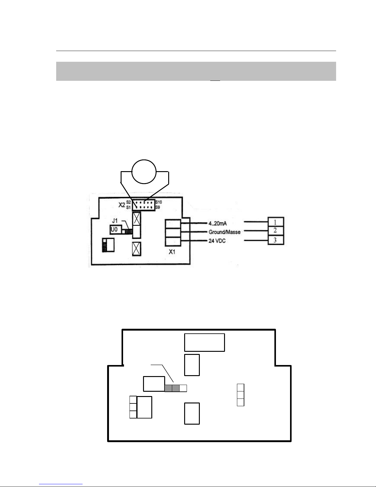
VV..SSTTRRUUCCTTUURREE OOFF TTHHEE TTCCOODD--IIR
R
VVII..MMOOUUNNTTIINNGG AANNDD IINNIITTIIAALL OOPPEERRAATTIIOON
N
The TCOD-IR should be mounted in a suitable position, eg on a wall, with the opening of the
transmitter pointing downwards. Allow a 10 cm gap between the head of the transmitter and any
other object for calibration.
Some space should also be allocated for cable insertion which is from the right-hand side. The
connecting cable should be placed above the transmitter to leave the opening of the sensor element
freely accessible.
WARNING
THE TRANSMITTER MUST NOT BE CONNECTED WITH REVERSED POLARITY. THE
ELECTRONICS CAN BE IRREPARABLY DAMAGED.
If the voltage input is already connected when power is supplied to the gas detection unit, the output
current may momentarily rise to 32 mA.
Alarm signals at the gas detection unit should be reset.
VVIIII..WWAARRMM--UUPP TTIIMME
E
Two minutes after power has been supplied, the transmitter is ready for operation.
For accurate calibration allow up to approx. 15 mins. for the sensor electronics to stabilise.
S2
S1
S10
S9
C
Z
F
S
U0
4.20 mA
Ground/Masse
24 VDC
Service Plug
IR-Sensor
element
PCB
Viton Seal
Plastic Screw M3
PTFE-Foil
Screen
X2
J1
X1
J2
J3
Warning !
Do not reverse
polarity
Page 9
9
VVIIIIII..CCAALLIIBBRRAATTIIOONN AANNDD AADDJJUUSSTTMMEENNT
T
WARNING :
Zero-Point Adjustment should only to be carried out on one sensor at a time.
• Zero-Point Adjustment of Sensor Element (Potentiometer UO (Zero voltage).
With the aid of a calibration cap, the sensor is subjected to zero gas (100% vol. N
2
) with a
volume flow of 0.5 l/min.
After approx. 5 min., the transmitter signal reaches its final state.
The voltage at the measured points X2:S1 (ground) and X2:S6 of the service terminal is
measured with a voltmeter (set mV DC).
The voltage is set to 0 mV DC with the potentiometer U0; voltage may indicate either positive or
negative values. Clockwise rotation of the potentiometer will increase voltage.
Should a positive voltage remain after turning the potentiometer U0 anti-clockwise as far as it
will go, the jumper J1 should be relocated into the left-hand position and the adjustment
repeated.
U0
J1
OLDHAM EQUIPMENTS
mV
Page 10

10
• Zero-Point Adjustment at Output Signal = 4 mA (Potentiometer Z (Zero)).
(The sensor is subjected to zero gas with a volume flow of 0,5l/min.).
Using an ameter (set to mA DC), the voltage is measured across the signal path of the "mA"
terminal (positive) , note, - the cable must be disconnected from this terminal.
Output voltage is set to 4 mA with potentiometer Z, clockwise turning of which increases the
output voltage.
• Span Adjustment at Output Signal (Potentiometer S (Span)).
The sensor is subjected to standard test gas with the aid of a calibration adapter (above 2nd
alarm level or in upper third of measuring range).
Output voltage in compliance with the calibration curve is set with potentiometer S, clockwise
rotation of which increases the output voltage.
Should the amplification not be enough if the potentiometer has been turned fully clockwise as
far as possible, the jumper J2 should be relocated into the upper position and the adjustment
repeated.
• Verification of Zero-Point and Span Calibration
Zero-point adjustment for 4 mA is once again repeated and checked. Should further adjustment
become necessary, span adjustment again needs to be repeated. Subsequent checking must
be repeated until deviations at 4 mA or with standard test gas are below approx. ± 0.1 mA.
J2
S
Z
mA
+
X1
Ground/Masse
24 VDC
mA
4..20 mA
Page 11

11
IIXX..TTeesstt GGaassees
s
Only certified test gases must be used. For calibration, the test gas concentration must be
known to ± 2% relative to the bottle value.
Zero gas: 100% Vol. N2 (nitrogen)
Standard Test Gas: CO2 (carbon dioxide) above 2nd alarm level or in upper third of
measuring range.
WARNING:
Ambient air must not be used for zero-point adjustment.
The logarithmic response characteristic of the IR sensor element generates a large signal with
CO2 . Concentrations in ambient air (> 400 ppm) would lead to a in accurate calibration.
XX..MMaaiinntteennaannccee aanndd CCaalliibbrraattiioonn iinntteerrvvaallss.
.
Maintenance of the transmitter should be carried out at 12-months intervals by a specialist with
the recommended test gases and in accordance with the calibration and test procedures.
XXII..MMaallffuunnccttiioonn SSTTAATTUUS
S
• Should, during test span adjustment, fail if the potentiometer S had been turned clockwise
as far as possible and the position of the jumper J2 has been changed, the sensor may be
damaged due to dust or ageing and needs to be changed.
• Should the output current be approx. 0 mA, the sensor element is probably faulty. In this
case, the sensor element should be replaced and the sensor re-calibrated.
XXIIII..AAcccceessssoorriieess aanndd SSppaarree PPaarrtts
s
Calibration Set
To guarantee the performance of the gas detection system, regular calibration should be carried
out.
Page 12
12
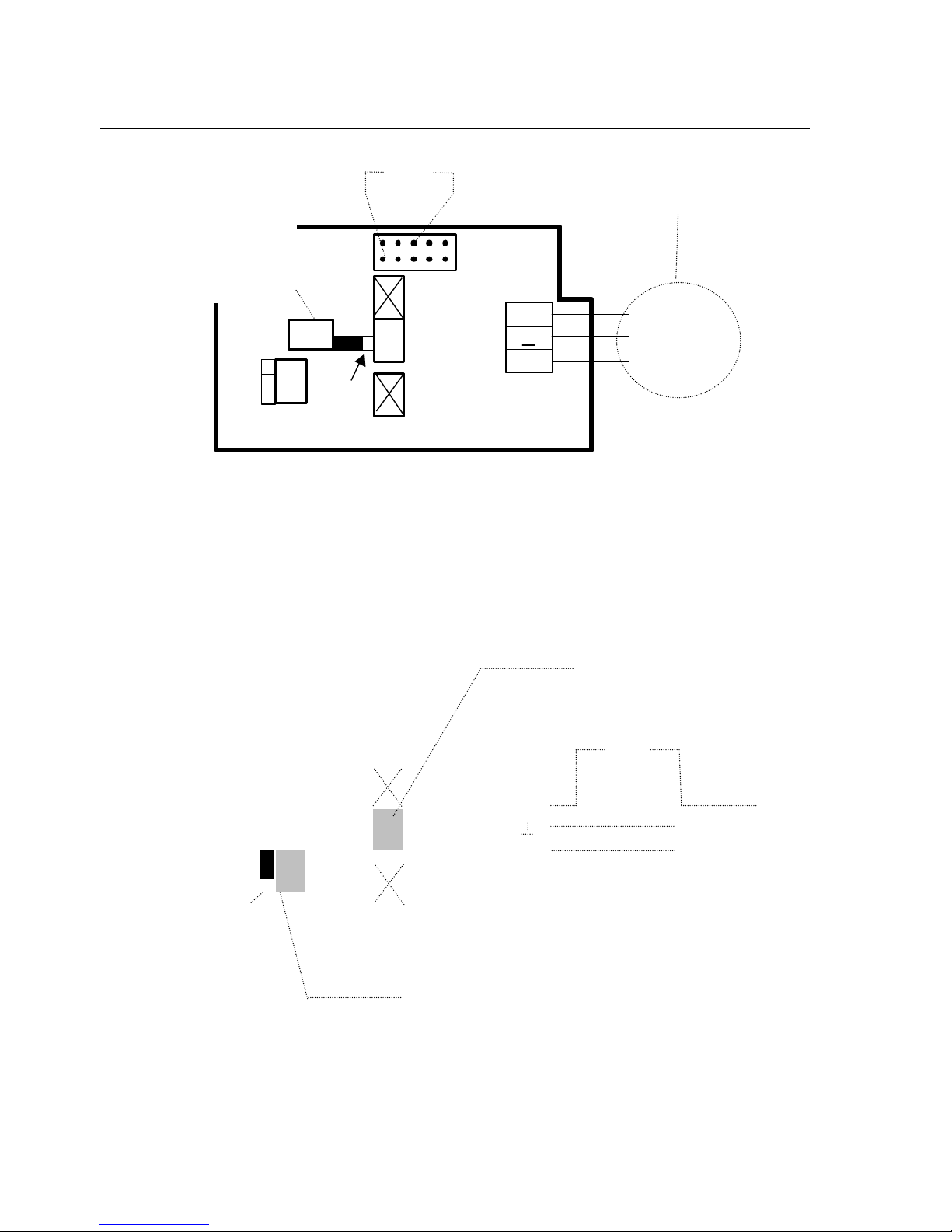
XXIIIIII..CCAALLIIBBRRAATTIIOONN PPRROOCCEEDDUURRE
E
UO
mA
+
X1
J1
X1
S2S1S10
S9
Ground/Masse
24 VDC
4..20 mA
1.
Zero point (0 mV)
Adjustment at 100 % Vol.
N
2
(change position of jumper J1
è Warning !!!
Do not reverse polarity.
mV
S
Z
mA
+
X1
Ground/Masse
24 VDC
mA
4..20 mA
J2
2.
Zero (4 mA)
Adjustement
at 100 % Vol. N
3.
Span
Adjustement according
to calibration curve
(Change position of jumper
Page 13

13
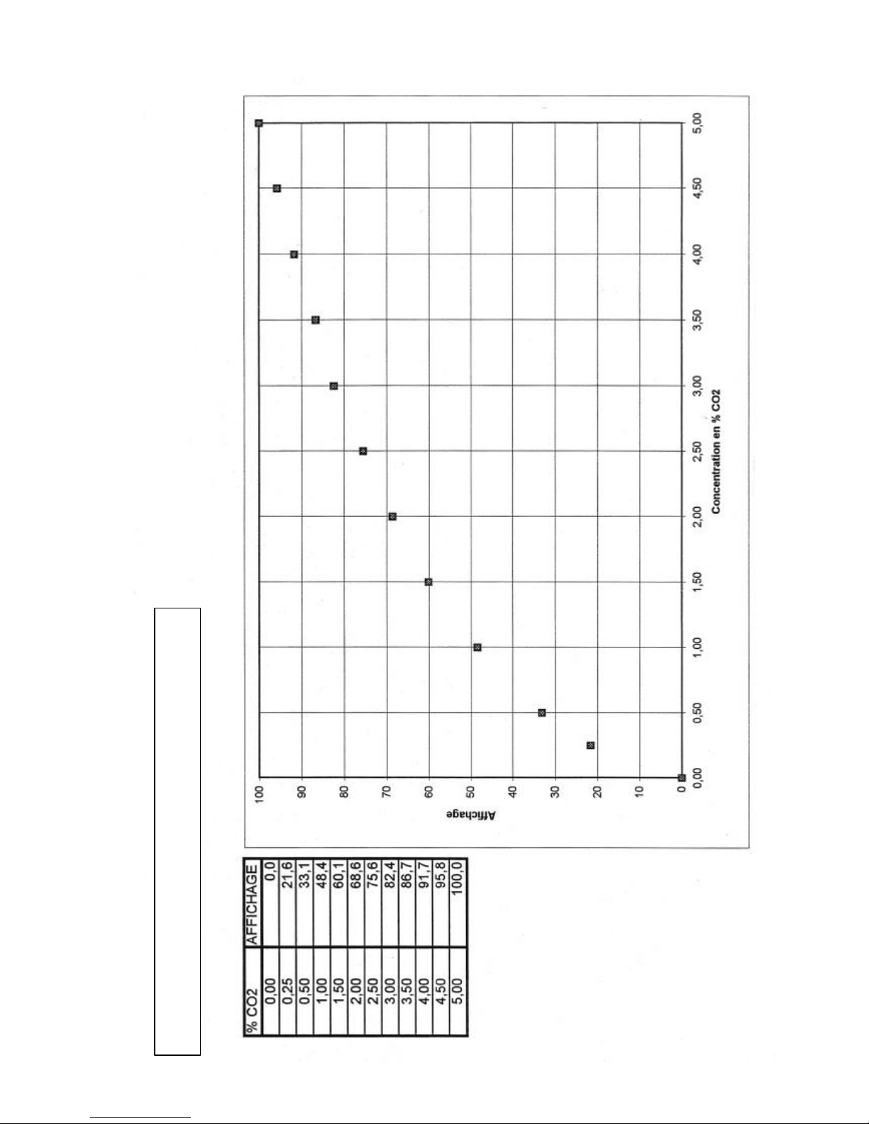
XXIIVV.
.
C
C
A
A
L
LII
B
B
R
R
A
A
T
TII
O
O
N
N
C
C
U
U
R
R
V
V
E
E
S
S
Page 14

14
Page 15

15
CO2 DETECTOR 0-3000 ppm measurement
range
Page 16

16
CO2 DETECTOR 0-10000 ppm (1%) measurement range
Page 17
17
CO2 DETECTOR 0-5% CO2 measurement range
Page 18

18
CO2 DETECTOR 0-10% CO2 measurement
range
Page 19

19
CO2 DETECTOR 0-50% CO2 measurement
range
Page 20

20
Page 21

21
OLDHAM ITALIA S.R.L.
Italia
' (39) 011 38 013 71
7 (39) 011 38 066 13
paolo.pozzato@oldham.it
 Loading...