


 Loading...
INSTALLATION AND OPERATING
MANUAL
Réf.: NPM42GB

GAS DETECTION
We are delighted that you have chosen an INDUSTRIAL SCIENTIFIC instrument and would like to thank you for your choice.
We have taken all the necessary measures to ensure that your instrument provides total satisfaction.
Now it is important to read this document carefully.
E X T E N T O F R E S P O N S I B I L I T Y
*INDUSTRIAL SCIENTIFIC declines its responsibility towards any person for material damage, physical injury or death resulting wholly or partly from inappropriate use, installation or storage of its equipment resulting from failure to observe instructions and warnings and/or standards and regulations in force.
*INDUSTRIAL SCIENTIFIC neither supports nor authorises any company, physical or moral person to assume responsibility on behalf of INDUSTRIAL SCIENTIFIC , even if it is involved in the sale of
INDUSTRIAL SCIENTIFIC products.
*INDUSTRIAL SCIENTIFIC cannot be held responsible for direct or indirect damage or be required to pay direct or indirect compensation resulting from the sale or use of any of its products IF THESE
PRODUCTS HAVE NOT BEEN DEFINED AND CHOSEN BY INDUSTRIAL SCIENTIFIC FOR THEIR SPECIFIC USE.
C L A U S E S C O N C E R N I N G P R O P E R T Y
*Drawings, plans, specifications and information included in this document contain confidential information that is the property of INDUSTRIAL SCIENTIFIC
*None of this information may be reproduced, copied, divulged or translated, by physical, electronic or any other means, nor used as the basis for the manufacture or sale of INDUSTRIAL SCIENTIFIC equipment or for any other reasons without prior consent from INDUSTRIAL SCIENTIFIC
W A R N I N G S
*This document is not contractually binding. In the interests of its customers, INDUSTRIAL SCIENTIFIC reserves to modify the technical specifications of its equipment without notice, in order to improve its performance.
*READ THIS MANUAL CAREFULLY BEFORE FIRST USE OF THE EQUIPMENT: this manual must be read by any person who is or will be responsible for using, maintaining or repairing this equipment.
*This equipment will only provide the announced performance levels if it is used, maintained and repaired according to INDUSTRIAL SCIENTIFIC directives, by INDUSTRIAL SCIENTIFIC personnel or by personnel approved by INDUSTRIAL SCIENTIFIC
G U A R A N T E E
2 years guarantee in normal conditions of use on parts and technical labour, return in our workshops, excluding consumables (sensors, filters, etc.)
3
CONTENT
1 |
DESCRIPTION (fig 1) .................................................................................................. |
7 |
||
2. |
INSTALLATION AND CONNECTIONS ....................................................................... |
9 |
||
2.1. |
Installation ............................................................................................................. |
9 |
||
2.2. Electrical connection of the MX 42A detection unit (fig 2)...................................... |
9 |
|||
2.3. Connection of the detection unit to the detectors .................................................. |
9 |
|||
|
2.3.1. Physical layout of detectors............................................................................ |
9 |
||
|
2.3.2 Type and connection of detectors (fig 3). ..................................................... |
11 |
||
2.4. Connection of the detection unit to external devices ........................................... |
13 |
|||
|
2.4.1. |
Connection to servocontrols ......................................................................... |
13 |
|
|
2.4.2. 4-20 mA current output................................................................................. |
13 |
||
3. |
START-UP AND OPERATION................................................................................... |
15 |
||
4. |
CONFIGURATION OF ALARMS AND SERVOCONTROL ....................................... |
17 |
||
4.1. Characteristics of alarm triggering ....................................................................... |
17 |
|||
4.2. |
Programming of parameters................................................................................ |
20 |
||
4.3. |
Servocontrol ........................................................................................................ |
23 |
||
|
4.3.1. |
Relays .......................................................................................................... |
23 |
|
|
4.3.2. 4-20 mA current output................................................................................. |
23 |
||
5. |
PERIODIC SERVICING.............................................................................................. |
25 |
||
5.1. Adjustment of detectors from the MX 42A detection unit..................................... |
25 |
|||
5.2. Local adjustment at the detectors........................................................................ |
26 |
|||
6. |
TROUBLESHOOTING ............................................................................................... |
27 |
||
7. |
DETAILED TECHNICAL CHARACTERISTICS ......................................................... |
28 |
||
7.1. |
Casing ................................................................................................................. |
28 |
||
7.2. |
Display................................................................................................................. |
28 |
||
7.3. |
Power supply....................................................................................................... |
28 |
||
7.4. |
Measurement inputs ............................................................................................ |
29 |
||
7.5. |
Alarm ................................................................................................................... |
29 |
||
7.6. |
Control functions.................................................................................................. |
30 |
||
7.7. |
Relaying .............................................................................................................. |
30 |
||
7.8. |
Output of measurements ..................................................................................... |
30 |
||
8. |
Scrapping of mx42a.................................................................................................. |
31 |
||
9. |
LIST OF MX42A SPARE PARTS............................................................................... |
31 |
||
9.1. |
Spare parts.......................................................................................................... |
31 |
||
9.2. Intrinsic barriers and accessories ........................................................................ |
31 |
|||
10. |
Special Specifications for use in Potentially Explosive Atmospheres in |
|
||
accordance with European Directive ATEX 94/9/EC..................................................... |
32 |
|||
10.1. Specifications for mechanical and electrical installation in Classified Areas. ... |
32 |
|||
10.2. |
|
Metrological Specifications............................................................................... |
32 |
|
4
10.3.Connecting detectors other than INDUSTRIAL SCIENTIFIC detectors to the
MX42A device ................................................................................................................ |
33 |
|
10.3.1. Device transfer curves in 0% to 100% LEL configuration ......................... |
33 |
|
10.3.2. Device transfer curves in 0% to 30.0% OXYGEN configuration ............... |
34 |
|
10.3.3. Power supply and load resistance characteristics .................................... |
34 |
|
10.4. |
MARKING ....................................................................................................... |
34 |
5
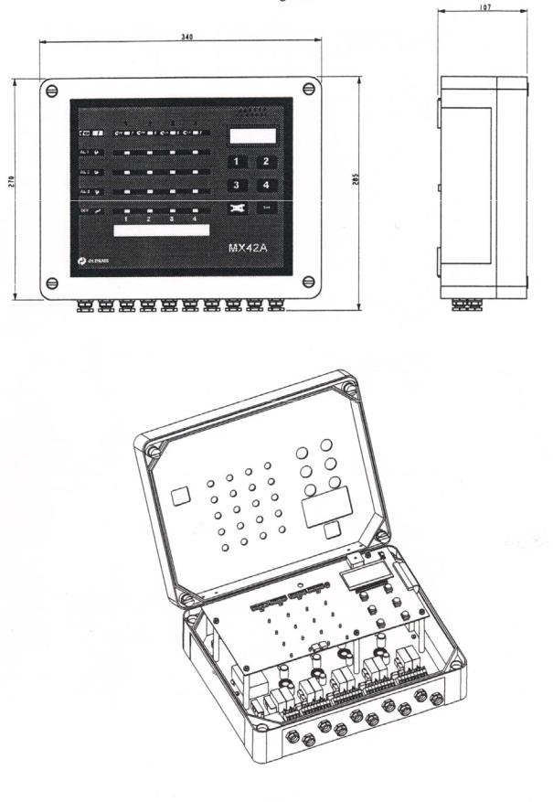
Figure 1
6

1 DESCRIPTION (fig 1)
The MX 42A detection unit is an apparatus for the detection and measurement of various combustible, toxic or oxygen-carrying gases.
The MX 42A detection unit has 4 independent measuring channels. Each channel is connected to a gas detector located in places to be monitored. The measurement from the detector is displayed on the MX 42A detection unit and compared to alarm thresholds. Should alarm thresholds be exceeded, the MX 42A detection unit actuates relays which can be used for the control of outside devices (horn, telephone call, exhaust fans, etc.).
Note: the detection unit also comes in a 2-measuring channel version.
Main characteristics: (cf Figure 1)
-Casing for wall mounting made of PVC (length: 340, height: 300, depth: 107) with intern "plating".
-AC or DC power supply
-4 measuring inputs for detectors of the explosimetric, toxic or oxygen type (or other type on request)
-Visualization of the measurement by LCD
-Alarms per channel:
2 increasing or decreasing thresholds, manual or automatic clearance (control logic of exhaust fans on programming)
1 increasing or decreasing threshold, automatic clearance, triggering on basis of time or on averaging
-Relaying: a total of 10 relays distributed as follows:
2 relays per channel (NO or NC) for the first two alarm thresholds
1 relay common to the channels for the third alarm threshold (or the remote transmission of the alarm on programming)
1 relay common to the channels for detector faults and anomalies
-4-20 mA output per channel (< 1 mA for fault, 2 mA for maintenance)
-Resettable buzzer should alarms or an anomaly appear
7

Figure 2
8

2.INSTALLATION AND CONNECTIONS
Please ensure you read the paragraph: Special Specifications for use in Potentially Explosive Atmospheres in Accordance with European Directive ATEX 94/9/EC
2.1.Installation
The detection unit can be installed in any place without an explosive atmosphere. It should be put in a well ventilated place where it can be watched (guard house, control room, security service...).
It is attached according to Figure 2: 4 attachment points, marked 1, 2, 3 and 4, with centres of 314 x 245 mm, using 5 mm screw.
Caution: So that the cover of the detection unit can be completely opened, there must be at least 30 cm of free space above it.
Before installation, switch off the MX42A with the switch located on the inside (bottom left corner).
2.2.Electrical connection of the MX 42A detection unit (fig 2).
Power supply: connect the power supply wires to the terminal blocks of the detection unit.
-Earth, live and neutral terminals, 220 V AC (207 V to 244 V), 50/60 Hz, protected by an F1 630 mA time-delay fuse.
-or + DC, - DC terminals, 24 V (19 V to 32 V), DC protected by an F2 4A fuse.
On option:
-either 115 V AC (103 V to 122 V), 50/60 Hz, protected by an F1 1.25 A time-delay fuse
-or 48 V (43 V to 60 V), protected by an F3 2 A time-delay fuse
A sticker on the casing gives the power supply voltages.
2.3.Connection of the detection unit to the detectors
2.3.1.Physical layout of detectors
Their location depends on three main factors:
-Density of gas to be detected: in elevation for gases lighter than air and low down for gases heavier than air
-Leak point: determination of the probable source of a leak
-In the flow of air in ventilated rooms.
9

Figure 3
Transmitters 4.20 mA / 2 wires.
Explosimetric transmitters (catalytic celles) with 3 wires
4.20 mA /3 wires for flammable gas transmitters
4.20 mA / 2 wires / transmitters for parking CO detection
10

2.3.2 Type and connection of detectors (fig 3).
3 types of detectors are to be differentiated:
-Explosimetric detectors of the BRIDGE type (no integrated electronics, 3 connecting wires of an armoured cable).
Resistance of detection unit - detector cable: maximum 8 ohms per wire (length 500 m, cable 3 x 1.5 mm²), or 16 ohms in a loop.
-Explosimetric detectors of the 4-20 mA type (a shielded cable with 3 wires of an armoured cable).
Resistance of detection unit - detector cable: maximum 16 ohms per wire (length 1 km, cable 3 x 1.5 mm²), or 32 ohms in a loop.
-Toxic gas or oxygen detectors of 4-20 mA type (a shielded cable with 2 wires).
Resistance of detection unit - detector cable: maximum 16 ohms per wire (length 1 km, cable 3 x 1.5 mm²), or 32 ohms in loop.
It is specified that
detectors are connected by SHIELDED CABLES
using shielded cables is compulsory
the screen of shielded cables must be connected to the earth at two extremities (detectors and control unit)
connections to the earth are considered as equipotential.
a) Parking garage application
Toxic gas detectors "Co-parking" type can be mounted in parallel in the event that it is necessary to obtain an average gas concentration. It is absolutely essential that the detectors be located in the same area. A max of, five detectors can be connected in parallel.
Connection of the Zener barrier
11
The Figure 4 describes the connection between the detector and the barrier
Figure 4
"i" transmitters
"i" transmitters Figure 5
12
Loading...