


Installation and
Operating Manual
MX 32
2 CHANNEL CONTROLLER
Reference: NPM32GB
Revision: B.1
The Fixed Gas Detection Experts

Copyright 2013 by Oldham
All rights reserved. Reproduction in any form, in whole or in part, without the express written consent of Oldham is strictly prohibited.
The information contained within this manual is true and correct to the best of our knowledge.
Due to ongoing research and development, the specifications of this product may be changed at any time without notice.
Oldham
Rue Orfila
Z.I. Est – CS 20417
F – 62027 ARRAS Cedex
Phone: +33 (0)3 21 60 80 80
Fax: +33 (0)3 21 60 80 00
iiMX 32
Instruction Manual

Table of Contents
Chapter 1 |
│General Information ................................................... |
1 |
The User’s Guide......................................................................................... |
1 |
|
Symbols used .............................................................................................. |
1 |
|
Safety Warnings .......................................................................................... |
2 |
|
Important Information .................................................................................. |
2 |
|
Limitation of liability ..................................................................................... |
2 |
|
Chapter 2 |
│General Introduction .................................................. |
3 |
Subject ........................................................................................................ |
|
3 |
View: Front internal...................................................................................... |
3 |
|
View: Front .................................................................................................. |
|
4 |
LCD Information .......................................................................................... |
5 |
|
View: Internal............................................................................................... |
5 |
|
Chapter 3 │ Installation and wiring .............................................. |
7 |
|
Mounting the controller ................................................................................ |
7 |
|
Wiring .......................................................................................................... |
|
8 |
Chapter 4 |
│Operating instructions ............................................. |
13 |
Displays ..................................................................................................... |
|
13 |
Navigating the menus ................................................................................ |
16 |
|
PRG Menu (Programming) ........................................................................ |
18 |
|
INI Menu (Initialization) .............................................................................. |
23 |
|
Cal Menu (Calibration)............................................................................... |
25 |
|
Cod Menu (Access code) .......................................................................... |
30 |
|
Buz Menu (Buzzer) .................................................................................... |
31 |
|
Chapter 5 │Cleaning, servicing and maintenance ..................... |
33 |
|
Cleaning .................................................................................................... |
|
33 |
Maintenance and servicing ........................................................................ |
33 |
|
Fuse replacement ...................................................................................... |
34 |
|
iiiMX 32
Instruction Manual

Parts .......................................................................................................... |
|
34 |
Chapter 6 |
│Technical specifications .......................................... |
35 |
Chapter 7 |
│Technical specifications .......................................... |
37 |
Chapter 8 |
│ Particular Specifications......................................... |
39 |
Specifications for mechanical |
|
|
and electrical installations in Explosive Zones. .......................................... |
39 |
|
Metrological specifications ......................................................................... |
39 |
|
Connecting detectors other than |
|
|
Oldham detectors to the MX 32 controller ................................................. |
40 |
|
Markings:................................................................................................... |
41 |
|
ivMX 32
Instruction Manual

Chapter 1 │General Information
The User’s Guide
Please read the following notice carefully before installation and start -up, paying particular attention to the end-user safety instructions. This user’s guide should be distributed to every individual involved in the start-up, use, maintenance or repair of the system. The information contained in this manual, the data and technical drawings are correct as of the date of publication. Should questions arise, please contact Oldham for additional information.
This manual is designed to provide users with simple and precise information. Oldham shall not be held responsible or liable for any misinterpretation that may result from the reading of this manual. Although every effort is made to ensure accuracy, this manual may contain unintentional technical inaccuracies.
On behalf of its clients, Oldham reserves the right to modify the technical characteristics of its equipment, without notice, to improve product performance. This user manual and its contents are the inalienable property of
Oldham.
Symbols used
Icon Meaning
This symbol indicates useful additional information.
This symbol indicates:
This equipment must be grounded.
This symbol indicates:
Safety grounding terminal. A cable of adequate diameter must ground any terminal with this signal.
This symbol indicates:
Caution: In the current operating mode, failure to adhere to the instructions preceding this symbol can result in a risk of electric shock or death.
This symbol indicates:
Please refer to the instructions.
Double isolation.
1 – General Information |
1 |
|
|
European Union (and EEA) only. This icon indicates that in accordance with Directive DEEE (2002/96/EC) and with the regulations of your country, this product may not be disposed with household waste.
Dispose of this product at a collection site intended for electrical waste, for example an official EEE (Electrical and Electronic Equipment) collection site with a recycling or take-back program for authorized products available to consumers whose purchases replace old EEE products with new equivalents.
Failure to comply with regulations for the disposal of this type of waste can be harmful to the environment and to public health, as EEE products typically contain potentially hazardous substances. Your complete cooperation in the disposal of this product will help to ensure a more efficient use of natural resources.
Safety Warnings
Icons have been placed on the central controller to call attention to general use safety precautions. These labels are an integral component of the central controller. Replace any label that has peeled off or become illegible. The meanings of these labels are explained below.
Installation and electrical connections must be performed by a qualified professional, according to the manufacturer’s specifications and to the standards of authorities in the field.
Failure to observe these rules may result in serious injury. Exactness, particularly regarding electricity and assembly (couplings, network connections) is imperative.
Important Information
The modification of any component or the use of any third party components will automatically void any and all guarantees.
The central controller is intended to be used for precise applications of a technical nature. Exceeding the indicated values is strictly prohibited.
Limitation of liability
Neither Oldham nor any other affiliated organization shall be held liable under any circumstances for any damage whatsoever including, without limitations, damages for loss of production, interruption of production, loss of information, controller failure, personal injury, loss of time, money, or materials, or for any indirect or consecutive consequence of loss occurring during the use of the product or the inability to use the product, even in the event that Oldham had been informed of such damages.
2MX 32
Instruction Manual
Chapter 2 │General Introduction
Subject
The MX 32 controller is intended for light units that do not require an electrical cabinet.
The MX 32 measurement and alarm controller can measure 1 or 2 channels independently. Each channel is linked to one or more sensors installed in the locations being monitored. The measurement from the sensor is displayed on the MX 32 controller and compared to the alarm thresholds. In the event that the measurement exceeds the threshold, the controller activates the relays which can be used to control external components.
View: Front internal
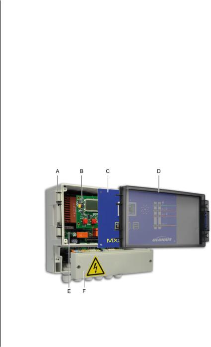
The MX 32 controller is composed of the following components:
■A wall-mounted enclosure (ref. A) equipped with a terminal cover (ref. F), a faceplate (ref. C) and a transparent hinged cover (ref. D) ;
■a power supply board (analog) (ref. E) ;
■a display card (microprocessor) (ref. B).
Figure 1: Overall view of the MX 32 controller components.
2 – General Introduction |
3 |
|
|
View: Front
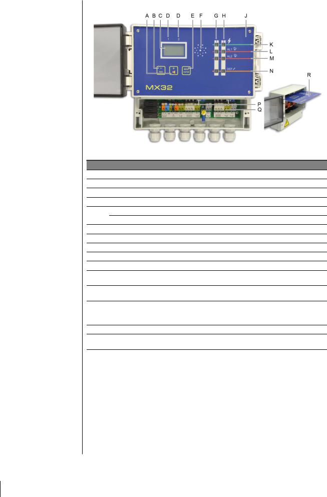
Figure 2: Full view of the MX 32 controller.
Ref. Function
A.Button to increase the value displayed or flip to the next menu/option.
B.Button to decrease the value displayed or flip to the previous menu/option.
C.LCD screen displaying measurements, menus and options.
D.Labels, for the LCD screen, indicating the display for Channel 1 or Channel 2.
E.Menu access button. See page 16. Button to confirm the value displayed.
F.Buzzer activated in the case of fault or alarm if authorization is granted. See page 31.
G.LEDs for Channel 1.
H.LEDs for Channel 2.
J.Removable faceplate; also see ref. R.
K.LED lights up when the channel is active.
L.Alarm threshold for level 1. LED lights up when the alarm threshold is exceeded or when programming the alarm threshold for the channel.
M.Alarm threshold for level 2. LED lights up when the alarm threshold is exceeded or when programming the alarm threshold for the channel.
N.Fault LED
■Lights up when there is a fault in the channel.
■Blinks during programming of the channel.
P.Access to the zero and sensitivity settings (Figure 4, ref. O to R).
Q.Connection terminals (sector, 24VDC, sensors, dry alarm contacts); front view with protective cover removed.
R . |
Removable faceplate in maintenance position. |
|
|
4MX 32
Instruction Manual

LCD Information
Figure 3: LCD Information.
Ref. |
Function |
See page |
A. |
Indicator for alarm threshold rising. |
13 |
|
|
|
B. |
Indicator that Channel 1 is selected. See Figure 2, ref. D. |
14 |
|
|
|
C. |
Digital indicator (measurement value, alarm threshold value, etc.) |
13 |
|
|
|
D. |
Indicator that Channel 2 is selected. See Figure 2, ref. D. |
14 |
|
|
|
E. |
Percent symbol. |
18 |
|
|
|
F. |
Negative sign. |
|
|
|
|
G. |
Indicator for alarm threshold falling. |
18 |
|
|
|
H. |
Symbol indicating level 1 alarm threshold (AL1) activated. |
18 |
|
|
|
J |
Symbol indicating level 2 alarm threshold (AL2) activated. |
18 |
|
|
|
K. |
Time delay after calibration (blocking the relays): the yellow LED blinks |
18 |
|
and the icon is displayed. |
|
|
|
|
L. |
A Maintenance key icon is displayed while the programming and |
18 |
|
calibration menu is being used. |
|
|
|
|
View: Internal
Figure 4: Internal view.
2 – General Introduction |
5 |
|
|

|
Ref. |
|
Function |
See page |
|
|
A. |
|
Configuration jumper (J03) for Fault* relay settings. |
10 |
|
|
|
■ Up position: Fault relay contact closed in alarm mode. |
|
||
|
|
|
|
|
|
|
|
|
■ Down position: Fault relay contact open in alarm mode. |
|
|
|
|
|
|
|
|
|
B. |
|
F7 Fuse (5x20, 250 V AC - 2 A T) with 24V DC power supply. |
8 |
|
|
|
|
|
||
|
|
|
|
|
|
|
C. |
|
F9 Fuse: |
8 |
|
■ 5x20, 250 V AC - 160 mA T with 230 VAC power supply. ■ 5x20, 250 V AC - 315 mA T with 115 VAC power supply.
D. |
F8 Fuse: |
8 |
■5x20, 250 V AC - 160 mA T with 230 VAC power supply.
■5x20, 250 V AC - 315 mA T with 115 VAC power supply.
E. |
Sector power supply terminal (230 V AC or 110 V AC upon request) with |
8 |
||
the following identifications: P (phase), N (neutral) and |
(ground). |
|||
|
|
|||
|
|
|
|
|
F. |
Power terminal block 24 V DC (0, + 24V). |
|
8 |
|
|
|
|
||
G. |
Fault relay terminal block. Contacts RCT, 250 V AC – 2 A. Contact |
10 |
||
status not in alarm mode as defined by J03 (ref. A). |
|
|||
|
|
|
||
|
|
|
|
|
H. |
Terminal block connection for channel #1 sensor. |
|
9 |
|
|
|
|
||
I. |
Relay terminal block RL 1 - Channel 1. Contacts RCT, 250 V AC – 2 A. |
10 |
||
Contact status not in alarm mode as defined by J10 (ref. X). |
||||
|
|
|||
|
|
|
|
|
J. |
Secondary ground connection. |
|
8 |
|
|
|
|
||
K. |
Relay terminal block RL 2 - Channel 1. Contacts RCT, 250 V AC – 2 A. |
10 |
||
Contact status not in alarm mode as defined by J05 (ref. V). |
||||
|
|
|||
|
|
|
|
|
L. |
Terminal block connection for channel #2 sensor. |
|
9 |
|
|
|
|
||
M. |
Relay terminal block RL 1 - Channel 2. Contacts RCT, 250 V AC – 2 A. |
10 |
||
Contact status not in alarm mode as defined by J08 (ref. W). |
||||
|
|
|||
|
|
|
||
N. |
Relay terminal block RL 2 - Channel 2. Contacts RCT, 250 V AC – 2 A. |
10 |
||
Contact status not in alarm mode as defined by J07 (ref. U). |
||||
|
|
|||
|
|
|
|
|
O. |
Zero settings (P4) for channel #2. |
|
26 |
|
|
|
|||
|
|
|
|
|
P. |
Sensitivity settings (P6) for channel #2. |
|
27 |
|
|
|
|||
|
|
|
|
|
Q. |
Sensitivity settings (P5) for channel #1. |
|
26 |
|
|
|
|||
|
|
|
|
|
R. |
Zero settings (P3) for channel #1. |
|
27 |
|
|
|
|||
|
|
|
||
S. |
Programming circuit (Explo 340 mA or 4-20 mA) for channel #1. |
- |
||
|
|
|||
|
|
|
||
T. |
Programming circuit (Explo 340 mA or 4-20 mA) for channel #2. |
- |
||
|
|
|||
|
|
|
|
|
U. |
Configuration jumper (J07) for Alarm 2*, channel #2 relay. |
|
- |
|
■Up position: relay contact closed in alarm mode.
■Down position: relay contact open in alarm mode.
V. |
Configuration jumper (J05) for Alarm 2*, channel #1 relay. |
- |
|
■ Up position: relay contact closed in alarm mode. |
|||
|
|
||
|
■ Down position: relay contact open in alarm mode. |
|
|
|
|
|
|
W. |
Configuration jumper (J08) for Alarm 1*, channel #2 relay. |
- |
■Up position: relay contact closed in alarm mode.
■Down position: relay contact open in alarm mode.
X. Configuration jumper (J10) for Alarm 1*, channel #1 relay.
■Up position: relay contact closed in alarm mode.
■Down position: relay contact open in alarm mode.
Y. |
F13 Fuse (5x20, 250 V AC – 630 mA T). |
- |
|
||
|
|
|
Z. |
F11 Fuse (5x20, 250 V AC – 630 mA T). |
- |
|
*alarm relays are configured as energized at the factory. This means that they are supplied with power when not in alarm.
6MX 32
Instruction Manual
Chapter 3 │ Installation and wiring
Mounting the controller
The MX 32 controller can be installed in any location except for explosive atmospheres. Ideally, the controller should be located in an area under surveillance (security office, control room, equipment room, etc.).
The central controller cover opens at a 90° angle to the left. Make sure to leave adequate space to completely open the cover once the central controller is mounted.
Figure 5: Dimensions of the controller
The dimensions for the wall-mounting of the enclosure are indicated on the back.
Figure 6: drilling dimensions for mounting the controller with three M4 screws.
3 – Installation and wiring |
7 |
|
|

Wiring
Before installing the controller, cut off the power supply.
Also refer to the Particular Specifications chapter on page 39.
The controller is intended for use in installation areas that meet Class II overvoltage requirements and Degree 2 pollution requirements.
The electrical connection must be:
■Performed by a specialist and conform to current regulations in force ;
■Compliant with NF C 15-100.
Verify the current and the grid power supply (the grid power supply must correspond to the supply indicated on the controller front plate). The operating voltage is configured at the factory.
The MX 32 does not have an on/off switch.
Certain power supplies can cause serious or fatal injury. All installation and wiring should be performed before turning on the power supply.
Incorrect installation can lead to measurement errors or system failure, all instructions in this manual must be followed carefully to guarantee proper system operation.
Ground Connection Protection
The controller must be connected to a functional ground connection.
The ground terminal (yellow) (Figure 4, ref. J) is indicated with the following symbol:  .
.
The cable used must have a minimum diameter of 1.5 mm² and a maximum diameter of 2.5 mm².
Refer to the wiring examples beginning on page 11.
Power
The MX 32 must be protected upstream by a differential bipolar circuit breaker. The response curve must be type D.
Power supply |
115 V AC |
230 V AC |
|
|
|
Differential bipolar circuit |
2 x 2 A |
2 x 1 A |
breaker caliber |
|
|
|
|
|
The cable used must have a minimum diameter of 1.5 mm² and a maximum diameter of 2.5 mm².
There are two options for transformers suggested for use as a power supply for the MX 32.
■Bobbin transformer (standard default).
■Toric Transformer (for connecting special sensors such as flame sensors, etc.).
8MX 32
Instruction Manual
Power supply 230 V AC
The sector power supply must be wired to the two terminals marked P (orange) and N (blue) (Figure 4, ref. E) on the 12 point terminal block for the power supply card; also see the wiring example on page 11. Protection is provided by fuses F8 and F9 (160 mA/250 VAC) (Figure 4, ref. C and ref. D).
Power supply 115 V AC
Protection is provided by fuses F9 and F8 (315mA/250 VAC) (Figure 4, ref. C and ref. D).
Power supply 24 V DC
Must be connected to the terminals marked 0 (grey) and +24V (orange) on the 12 point terminal block for the power supply card (Figure 4, ref. F) as indicated by the wiring example on page 11. Protection is provided by fuse F7 (2A/250 VAC) (Figure 4, ref. B).
Measurement Channels
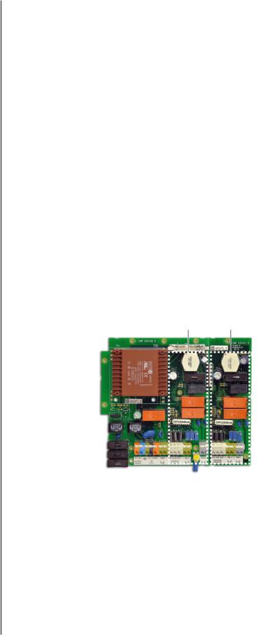
The MX 32 controller can be equipped with one or two adjustable and dual measurement channels (see Figure 7). Three options are suggested at purchase:
■MX 32 with 2 measurement channels (dual);
■MX 32 with 1 measurement channel (dual);
■1 extension card (to add on to a 1-channel controller).
The MX 32 controller will automatically recognize the number of measurement channels installed (display).
Channel 1 |
Channel 2 |
Figure 7: the 2 measurement channels for the controller.
Sensors
The sensors must be connected to points C1, C2 and C3 on the 12 point connector for each channel card, as indicated on the wiring example on page 10.
Wheatstone bridge 3 active wire explosive gas detectors
■C1: mid-point (signal).
■C2: detector filament.
■C3: compensator filament.
3 – Installation and wiring |
9 |
|
|

4/20 mA 2 active wire sensors/transmitters
■C1: signal (return to ground).
■C2: not connected
■C3: positive power supply (+24 Volts).
4/20 mA 3 active wire sensors/transmitters
■C1: signal (return to ground).
■C2: power supply (0 Volts).
■C3: positive power supply +24 Volts.
Note
For each family of sensors, on the measurement channel circuits:
■Programming will be carried out by Oldham (programming circuit pads).
■A programming circuit (Explo 340 mA or 4-20 mA) will be inserted on the mounting by the manufacturer (Figure 4, ref. S and T).
Alarm relays
The MX 32 controller uses two alarm relays per measurement channel which correspond to two instant pre-programmed alarm thresholds 1 and 2.The relays are energized (de-energized available on request) and voltage-free.
■The relay corresponding to alarm 1 is connected to the RL1 (green) terminals on the 12 point connector for each channel card.
■The relay corresponding to alarm 2 is connected to the RL2 (grey) terminals on the 12 point connector for each channel card.
The relay contacts can be used "normally open" (NO) or "normally closed" (NC) by flipping the corresponding switch (Figure 4, ref. U or V for AL1 alarms and references W and X for AL2 alarms).
Refer to the wiring examples beginning on page 11.
Relay fault
The MX 32 controller uses one "Fault" alarm per measurement channel (visual and auditory) but a single shared "Fault" relay for both channels. The fault relay is energized and voltage-free. The shared fault relay can be connected to the points marked DEF (fault) on the 12 point terminal block for the power supply card.
The relay contact can be used "normally open" (NO) or "normally closed" (NC) by flipping the corresponding switch (Figure 4, ref. L).
Refer to the wiring examples beginning on page 11.
Wiring examples
The following pages contain two examples of wiring.
10MX 32
Instruction Manual

Grounding sector
0V DC
+24 V DC
The AL1 and AL2 relays can be programmed as energized or de-energized (factory settings).
The fault relays are energized.
The contact relays are available on the NO or NC terminals according to the position of the switch next to each relay.
*Capacity to cut the power to relays 120 VA30W resistive; use a relay with external power source if necessary.
|
Contact alarm |
|
|
Channel 2. |
|
Fuse or |
Contact alarm |
|
Channel 1. |
||
circuit breaker |
||
|
Fuse
Telephonic
transmitter
To the telephone line
Gas valve, closed when power is cut off*
Shared fault indicator
Figure 8: MX 32 controller with 1 explosive sensor on Channel 1 and dual explosive sensors on Channel 2.
3 – Installation and wiring |
11 |
|
|
 Loading...