


COMMISSIONING, OPERATING AND MAINTENANCE MANUAL
MX 52
MEASURING UNIT
Part Number: NP52UGB
Revision: B.0
The Fixed Gas Detection Experts
Copyright April 2016 by Oldham S.A.S.
All rights reserved. The reproduction of all or any section of this document in any form whatsoever without the written permission of Oldham S.A.S. is forbidden.
The information contained in this manual is accurate to our knowledge.
As a result of continuous research and development, the specifications of this product may be modified at any time without prior notice.
Oldham S.A.S. Rue Orfila
Z.I. Est – CS 20417 62027 ARRAS Cedex Tel.: +33 (0)3 21 60 80 80 Fax: +33 (0)3 21 60 80 00
E-mail: info@oldhamgas.com Website: http://www.oldhamgas.com
2

GAS DETECTION
We are delighted that you have chosen an OLDHAM instrument and would like to thank you for your choice.
We have taken all the necessary measures to ensure that your instrument provides total satisfaction. Now it is important to read this document carefully.
E X T E N T O F R E S P O N S I B I L I T Y
*OLDHAM declines its responsibility towards any person for material damage, physical injury or death resulting wholly or partly from inappropriate use, installation or storage of its equipment resulting from failure to observe instructions and warnings and/or standards and regulations in force.
*OLDHAM neither supports nor authorises any company, physical or moral person to assume responsibility on behalf of OLDHAM , even if it is involved in the sale of OLDHAM products.
*OLDHAM cannot be held responsible for direct or indirect damage or be required to pay direct or indirect compensation resulting from the sale or use of any of its products IF THESE PRODUCTS HAVE NOT BEEN
DEFINED AND CHOSEN BY OLDHAM FOR THEIR SPECIFIC USE.
C L A U S E S C O N C E R N I N G P R O P E R T Y
*Drawings, plans, specifications and information included in this document contain confidential information that is the property of OLDHAM
*None of this information may be reproduced, copied, divulged or translated, by physical, electronic or any other means, nor used as the basis for the manufacture or sale of OLDHAM equipment or for any other reasons without prior consent from OLDHAM
W A R N I N G S
*This document is not contractually binding. In the interests of its customers, OLDHAM reserves to modify the technical specifications of its equipment without notice, in order to improve its performance.
*READ THIS MANUAL CAREFULLY BEFORE FIRST USE OF THE EQUIPMENT: this manual must be read by any person who is or will be responsible for using, maintaining or repairing this equipment.
*This equipment will only provide the announced performance levels if it is used, maintained and repaired according to OLDHAM directives, by OLDHAM personnel or by personnel approved by OLDHAM
G U A R A N T E E
2 years guarantee in normal conditions of use on parts and technical labour, return in our workshops, excluding consumables (sensors, filters, etc.)
3
4
CONTENTS
1. |
DESCRIPTION.............................................................................................. |
7 |
1.1. |
General............................................................................................................................. |
7 |
1.2. |
Rack.................................................................................................................................. |
8 |
1.3. The various printed circuit boards................................................................................... |
8 |
|
2. |
INSTALLATION AND CONNECTIONS .................................................. |
9 |
|
.1. |
Installation: recommendations ............................................................................................ |
9 |
|
.2. Electrical connections of the MX52 Unit (Fig. 8)................................................................ |
9 |
||
|
2.2.1. |
Alternative power supply ......................................................................................... |
9 |
|
2.2.2. |
DC power supply ................................................................................................... |
10 |
.3. Detectors (Figures 9 and 12) ............................................................................................. |
10 |
||
|
2.3.1. Explosimetric detectors of PONT type .................................................................. |
10 |
|
|
2.3.2. 3-wire detectors 4-20 mA: 3 connecting wires for shielded cable......................... |
11 |
|
|
2.3.3. 2-wire detectors 4-20 mA: 2 connecting wires for shielded cable......................... |
11 |
|
|
2.3.4. FIRE detectors: 2 connecting wires for shielded cable.......................................... |
11 |
|
2.3.5.FLAME detectors: 2, 3 or 4 connecting wires for shielded cable depending on
utilization ............................................................................................................................... |
11 |
||
2.3.6. |
CO2 detector of type “Ventostat VT”.................................................................... |
13 |
|
2.3.7. |
Specific case of intrinsic safety detectors .............................................................. |
13 |
|
2.3.8. |
Other detectors with standardized current output .................................................. |
14 |
|
2.3.9. |
Parking application ................................................................................................ |
14 |
|
.4. Connecting the unit to external devices ............................................................................. |
15 |
||
2.4.1. |
Slaving controls...................................................................................................... |
15 |
|
2.4.2. |
4-20 mA current outputs (Fig. 12) ......................................................................... |
16 |
|
2.4.3. |
RS 232 and RS 485 outputs ................................................................................... |
16 |
|
2.4.4. |
Remote acknowledgement ..................................................................................... |
18 |
|
3. |
STARTING UP ............................................................................................ |
19 |
|
3.1. |
Checking the installation ............................................................................................... |
19 |
|
3.2. |
Switching on the unit...................................................................................................... |
19 |
|
3.3. |
Operating modes ............................................................................................................ |
20 |
|
3.3.1. |
Audio warning device (buzzer).............................................................................. |
20 |
|
3.3.2. |
Light-emitting diodes (LED) (Fig. 26) .................................................................. |
20 |
|
3.3.3. |
Alarm thresholds .................................................................................................... |
20 |
|
3.3.4. |
Fault thresholds ...................................................................................................... |
25 |
|
3.3.5. |
Measuring unit ....................................................................................................... |
26 |
|
|
|
5 |
|
4. UTILIZATION ............................................................................................ |
27 |
4.1.List and functions of the various items of “USER” equipment for programming and
calibration of the unit................................................................................................................. |
27 |
|
4.1.1. |
Keypad (see Figures 26 and 4)............................................................................... |
27 |
4.1.2. |
Maintenance keys................................................................................................... |
28 |
4.1.3. |
Potentiometers........................................................................................................ |
28 |
4.2. Menus ............................................................................................................................. |
29 |
|
4.2.1. |
The various menus and their functions .................................................................. |
29 |
4.2.2. |
Block diagram of the scrolling of the various menus ............................................ |
29 |
4.2.3. |
Detailed flow diagrams of each menu.................................................................... |
31 |
5. |
SETTING THE MX52 UNIT INTO SERVICE ....................................... |
45 |
||
|
5.1. |
Programming the unit .................................................................................................... |
45 |
|
|
5.2. Programming the measuring channels .......................................................................... |
45 |
||
|
5.2.1. |
Programming.......................................................................................................... |
45 |
|
|
5.2.2. |
Copy ....................................................................................................................... |
46 |
|
|
5.3. |
Calibrations ................................................................................................................... |
46 |
|
|
5.4. 4-20 mA output adjustment for a measurement channel................................................ |
50 |
||
6. |
|
MAINTENANCE......................................................................................... |
51 |
|
|
6.1. Periodic / preventive maintenance................................................................................. |
51 |
||
|
6.1.1. On the MX52 unit .................................................................................................. |
51 |
||
|
6.1.2. |
On the detectors ..................................................................................................... |
51 |
|
|
6.2. Failures: causes and remedies....................................................................................... |
52 |
||
|
6.3. |
Scrapping of MX52 ........................................................................................................ |
55 |
|
|
6.4. List of spare and replacement parts............................................................................... |
55 |
||
7. |
VIEWS SPECIFIED IN THE MANUAL ................................................. |
57 |
||
8. |
|
DETAILED TECHNICAL CHARACTERISTICS ................................. |
87 |
|
9.Special Specifications for use in Potentially Explosive Atmospheres in
accordance with European Directive ATEX 94/9/EC. ....................................... |
89 |
6

1. DESCRIPTION
1.1. General
The MX52 measuring and alarm unit can be fitted with between one and 16 independent channels.
Each channel is connected to one or more detectors installed in the locations to be monitored.
The measurement that is output from the detector is displayed on the MX52 unit and compared with alarm thresholds. If thresholds are exceeded, the unit actuates relays which can be used to control external devices.
REMARK
The equipment of the MX52 unit comprises line PCBs, each equipped with two channels. However, each channel is independent and can be connected to any type of OLDHAM detector provided that the PCB is suitably programmed. The number of line PCBs is always equal to the mixed even number greater than the number of channels used divided by two.
MAIN CHARACTERISTICS
Rack 3U 19”
AC or DC power supply
16 measuring inputs for detectors
Display of measurement on a plasma display panel (2 lines - 16 characters)
One keypad with four keys for the user
One “CALIBRATION” key and one “PROGRAMMING” key for maintenance
(accessible only by opening the front panel)
3 gas alarms per channel
-Two instantaneous rising or falling thresholds, manual or automatic clearing, with
“extractor control logic (tunnel parking application)”
-One rising or falling threshold, automatic clearing, triggering by time delay or average
Relaying
Total of 34 relays distributed as follows:
-Two relays per channel, with positive or negative safety, contacts open or closed at rest for the first two thresholds
7

-One relay common to channels for third thresholds or for all alarms (buzzer transmission), with positive or negative safety, contacts opened or closed at rest
-One relay common to channels for faults and failures, constant positive safety mode, contacts open or closed at rest.
Current output (4-20 mA) per measuring channel.
Common audio alarm that can be acknowledged in the case of occurrence of gas alarms.
1.2.Rack
The MX52 rack is of the 3U 19” type.
Overall dimensions: Fig. 1
Overall view, front profile: Fig. 2
Overall view, back profile: Fig. 3
1.3.The various printed circuit boards
Overall view: Fig. 4
Power board and module: Fig. 5
MICRO board: Fig. 6
Measuring channel board: Fig. 7
Front connection board: Fig. 4
8

2. INSTALLATION AND CONNECTIONS
Please ensure you read the paragraph: Special Specifications for use in Potentially Explosive Atmospheres in Accordance with European Directive ATEX 94/9/EC
.1. Installation: recommendations
The MX52 unit can be installed in any premises without an explosive atmosphere. They should preferably be placed in a ventilated and monitored location (guardhouse, control room, instrumentation room, etc.).
Attachment is to be ensured in accordance with the dimensions in Figure 1 (four attachment points).
REMARK
In order to permit the swivelling front panel of the unit to be opened completely, allowance must be made for opening by rotation through 180° downwards.
Before making any connections, the unit should be switched off using the main On/Off switch below and to the left of the FRONT circuit (see Figures 4 and 26).
.2. Electrical connections of the MX52 Unit (Fig. 8)
The MX52 unit is equipped with a pulse automatic device which enables to connect 24 V DC voltage in a lack of 220 V AC voltage so we can use no expansive save power supply.
2.2.1.Alternative power supply
-Voltage: 230 V AC (207 to 244 V) 50/60 Hz
-Maximum power: 300 VA
-Maximum current in cable: 1.5 A
-Cable: 3 x 1.5 mm² (including earth)
-Location of connection terminal blocks: Fig. 8, item A
-Protection: the phase and neutral wires are protected by time-delayed 2 A fuses located at the rear of the power module.
-Voltage: 103 to 122 V AC - 50/60 Hz on option
CAUTION
It is mandatory that the appliance must be earthed. A terminal is reserved for this purpose at the back of the power module: see Fig. 5. This connection is required in order to ensure correct operation of the following:
-mains power interference filter,
-protective devices against electromagnetic interference.
9

2.2.2.DC power supply
-Voltage: 21 to 30 V continue. The "-" from continue power supply is linked to earth (and earth being linked to frame).
-Maximum power: 240 W
-Maximum current in cable: 12.5 A
-Cable: 2 x 2.5 mm² or 2 x 4 mm² depending on length
-Location of terminal block: see Fig. 8, item D
-Protection: by two fuses located at the back of the power module (Fig. 8, item E)
.3. Detectors (Figures 9 and 12)
REMARK
-The detectors are linked by SHIELDED cables.
-The utilization of shielded cables is MANDATORY
-The earth braid of shielded cables must be connected to the earth at one end only.
CAUTION
Each channel is configured in the factory for a given type of detector (explosive gas, toxic gas, fire or flame). If two different types of detector are interchanged, this may result in the destruction of the central unit or of the detector.
2.3.1.Explosimetric detectors of PONT type
Three connecting wires for a shielded cable.
Resistance of detector / unit cable: 16 ohms maximum per wire, i.e. 32 ohms in loop (1 km for cable 3 x 1.5 mm²).
Connection on MX52 unit: see Fig. 10
10
2.3.2.3-wire detectors 4-20 mA: 3 connecting wires for shielded cable
-Resistance of detector / unit cable: 16 ohms maximum per wire, i.e. 32 ohms in loop (1 km for cable 3 x 1.5 mm²).
-Connection on MX52 unit: see Fig. 10.
2.3.3.2-wire detectors 4-20 mA: 2 connecting wires for shielded cable
-Resistance of detector / unit cable: 32 ohms maximum per wire, i.e. 64 ohms in loop (2 km for cable 2 x 1.5 mm²).
-Connection on MX52 unit: see Fig. 11.
2.3.4.FIRE detectors: 2 connecting wires for shielded cable
The current commercial designations are as follows:
-“Thermovelo” detectors of type EC 11 (sensitive to temperature variations)
-Ionic detectors of type EI 1 100 (sensitive to smoke)
-Optical detectors of type EO 1 100 (sensitive to smoke)
-Resistance of detector / unit cable: 28 ohms maximum per wire, i.e. 56 ohms in loop (2 km for cable 2 x 1.5 mm²)
-Fire detectors can be detected in parallel to a maximum of five. The end-of-loop resistor (2.7 K) is to be placed at the end of the line on the last detector.
-Connection on MX52 unit: see Fig. 11.
2.3.5. FLAME detectors: 2, 3 or 4 connecting wires for shielded cable depending on utilization
REMARK
The detectors can be supplied with power either via the MX52 unit or by an auxiliary 24 V DC source.
11
These detectors can operate in standalone mode:
24 V DC power supply and direct utilization of relay contacts in accordance with the technical specification corresponding to the detector used.
The current commercial designations are as follows:
-model 20/20 U - analog - type UV - 752002 (sensitive to UV radiation)
-model 20/20 UC - analog - type UV (sensitive to UV radiation)
-model 20/20 UB - µP technology - type UV - 772002 (sensitive to UV radiation)
-model 20/20 UBC - µP technology - type UV (sensitive to UV radiation)
-model 20/20 LC - analog - type UV/IR (pyroelectric, combination of UV and IR detectors)
-model 20/20 LBC - µP technology - type UV/IR (pyroelectric, combination of UV and IR detectors)
-model 20/20 I - µP technology - triple IR detector - 780002 (pyroelectric, sensitive to IR radiation)
These detectors are equipped with various types of terminal block (see table below).
Model |
20/20 U |
20/20 UC |
20/20 UB |
20/20 LC |
20/20 UNC |
20/20 LBC |
20/20 I |
Type |
|
|
|
|
|
|
|
of terminal |
B |
C |
A |
C |
C |
C |
A |
block |
|
|
|
|
|
|
|
|
|
|
|
|
|
|
|
|
|
|
|
|
|
|
|
-Resistance of cable / unit
-In the case of local 24 V DC power supply:
8.5 ohms maximum per wire, i.e. 17 ohms in loop
-In the case of power supply via the MX52 unit: 3 ohms maximum per wire, i.e. 6 ohms * in loop
4 ohms for detector 20/20 I (IR3)
-Connection on MX52 unit (ONE detector per measuring channel ONLY):
-detector equipped with a terminal block of type A: see Fig. 13
-detector equipped with a terminal block of type B: see Fig. 14
-detector equipped with a terminal block of type C: see Fig. 15
Example of the utilization of the 4-20 mA signal from flame detectors equipped with connectors of type A or C: see Fig. 16.
Example of the utilization of detectors equipped with connectors of either type A or type B and with auxiliary power supply. The auxiliary power supply must be able to supply power to the number of detectors planned in the measuring loop (see Fig. 17).
12

REMARK
In the case of this application, the maximum of five flame detectors can be connected in the measuring loop.
Example of the utilization of IR3 or UV/IR detectors equipped with connectors of type A with a local junction box and galvanic insulation (see Fig. 18).
2.3.6.CO2 detector of type “Ventostat VT”
-Connection on MX52 unit: see Fig. 20.
-Resistance of detector/unit power cable: 12 ohms maximum per wire, i.e. 24 ohms in loop.
-4-20 mA output: maximum load = 280 ohms (whole loop)
2.3.7.Specific case of intrinsic safety detectors
Two types of intrinsic safety barrier can be used: Z787 / EX and MTL787S+.
PRECAUTIONS
Before connecting the barrier to the unit, check that the voltage is < 25 V DC.
-A short circuit in the electrical connections will result in destruction of the barrier.
-Perform wiring in the DE-ENERGIZED state.
-The electrical link between the MX52 unit and the clipper is made using a screened cable with two active conductors with a maximum resistance of 12 ohms each.
REMARK
In classified areas, the installation must comply with the standards in force.
-Connections on MX52 unit: see Fig. 21.
IMPORTANT
All intrinsic safety installations must be APPROVED as a whole assembly by an approved organization (DRIRE, etc.).
13

OLDHAM “INTRINSIC SAFETY” BARRIERS
|
Type of IS |
Reference |
Specific features |
OLDHAM box |
|
|
barrier |
|
|
reference |
|
|
Z787 / EX |
6184703 |
To be fitted on DIN |
|
|
|
|
|
RAIL |
|
|
|
MTL787S+ |
6797100 |
To be fitted in an |
For 2 clippers |
6797192 |
|
|
|
approved box: |
|
|
|
|
|
MANDATORY |
|
|
|
|
|
|
For 5 clippers |
6797547 |
|
|
|
|
For 12 clippers |
6797101 |
|
|
|
|
|
|
2.3.8.Other detectors with standardized current output
Any detector (with 2 wires or 3 wires) that can be supplied with power between 19 V DC and 32 V DC and that supplies a standardized current (signal) of between 4 and 20 mA can be connected to the MX52 unit.
The connection requirements are identical to those for the corresponding OLDHAM detectors (see Fig. 22).
2.3.9.Parking application
CTX300 "Co parking" toxic gas detectors can be fitted in parallel when a mean gas concentration is to be obtained. The detectors must, imperatively, be located in the same area. In this case, a maximum of five detectors can be connected (see Fig. 23).
14

.4. Connecting the unit to external devices
2.4.1. Slaving controls
The 16 measuring channels of the MX52 unit are each equipped with two relays which can be used to control external devices: sirens, solenoid valves, extractors, telephone calls, etc..
For each measuring channel, the relays are distributed in the following manner (see Fig. 7):
-a relay associated with the triggering of alarm 1,
-a relay associated with the triggering of alarm 2,
-use of open or closed contacts selected with a jumper (see Fig. 7),
-use of positive or negative safety selected by programming (see the CHANNEL programming menu),
-contact outputs on the back of the measuring board (see Fig. 12).
-An example of connection is given in Fig. 24:
-a siren connected to relay AL1 will be actuated as soon as alarm 1 is triggered,
-a solenoid valve connected to relay AL2 will be actuated as soon as alarm 2 is triggered.
For all channels:
-A common relay associated with the triggering of alarm 3 for the 16 channels.
By programming, this common relay can also be used for the remote transmission of the audio warning signal. (This relay will then be associated with all the unit’s alarms). The 3 contacts are available back to power supply module (fig 8).
-A fault relay associated with the triggering of channel faults (detector failures, electrical connections, excessively negative zero, etc.). This relay will always be in positive safety mode (see Fig. 5). The use of open or closed contacts is selected by programming on common board.
-Common relay contact outputs on the back of the power module: Fig. 8.
REMARK
Owing to the breaking capacity of the MX52 unit’s relays which is limited to 2 A / 250 V AC or 30 V DC, external intermediate relays must be used if the devices to be controlled require high power levels.
15
2.4.2. 4-20 mA current outputs (Fig. 12)
For each measuring channel, the MX52 unit is equipped with a 4-20 mA output that can be used to retransmit measurements to a recorder or an external PLC. The maximum resistance in loop mode is 600 ohms. The earth connections for the 4-20 mA outputs are common and the unit. The 4-20 mA lines are not galvanically insulated one from the other. The current output varies according to the measurement and has several states, as follows:
-On starting up the unit: I < 1 mA
-With FAULT: I < 1 mA
-In MAINTENANCE mode: I = 2 mA
-ZERO MEASUREMENT: I = 4 mA
-Full scale: I = 20 mA
-Out of range or “in doubt”: I > 23.2 mA
An example of the connection of a multi-channel recorder is given in Fig. 25.
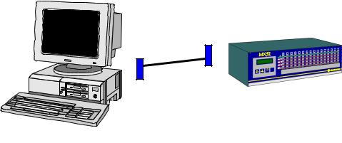
2.4.3. RS 232 and RS 485 outputs
RS232 OUTPUT
A computer can be connected on a female sub.D/DB9 type connector located on the back of the micro board (fig6 repA). The MX52 programming, from outside, will be possible thanks to this connection.
RS 232 OUTPUT USING
-Remove the DB9 connector (pmug with an internal strap)
-Connect a link cable ref.6315831 which will link the monitor to the computer on the MX52 available female connector DB9 (repA Fig6)
PC COMPUTER
ORDINATEUR PC
MX52
Male DB9
Female DB9
Cordon liaison PC/MX52
-when the using is stopped : no connect the cable and put the male DB9 "plug" again.
16
RS 485 OUTPUT (PINABLE ON FIG 29)
Several MX52 units can be linked to a single computer, which is the "master" of the network. In this case, a "SLAVE NUMBER" (by programming/unit) is asigned to each MX52 unit.
This RS 485 output can be galvanically insulated as an option.
1st case : no galvanic insulation
-no mounted insulation component
-2 polarization electrical resistances are programmed and welded
2nd case : with galvanic insulation
-mounted and welded insulation component
-no programmed polarization electrical resistance for "plu" (+ 5V)
a)with RS 485 shielded
-no programmed polarization resistor for "moins" (GND)
b)without RS485 shielded
-programmed polarization resistor for "moins" (GND)
End loop resistor
It is located on the MX52 micro board and must be programmed with the last MX52 unit of the loop (by pins) with a 120 Ohms value.
The MX stored data are some instantaneous values
The RS485 output is a half duplex type.
RS 485 OUTPUT USING
-No change the sub D/DB9 "plug" connector
-Connect the screwed connector terminals 3,4 and 5, located on the back of the MX52 unit (repB Fig6). See connection details fig 29.
-Owing to mounted wires or not (following the mounting and the equipment linked or not on the earth…).
17

IMPORTANT
All details regarding the RS 485 complete description (Modbus / Jbus format, structures, adresses aso…) are developped in a leaflet ref. D 813 577.
CAUTION
A computer must be used in order to printout the data stored by the MX52 unit.
Several MX52 units can be connected to a single computer which is the "MASTER". In this case, a SLAVE number is assigned to each MX52 unit.
2.4.4. Remote acknowledgement
It is possible to allow remote acknowledgement by connecting on connector 5 plugs, on the back or the micro board : see fig 6 item B.
18

3. STARTING UP
3.1. Checking the installation
It is checked that, at least, all connections have been made and that the complete installation complies with current standards in force.
CAUTION
OLDHAM is not responsible for the compliance of the complete electrical safety system.
The MX52 unit is switched on by means of circuit breakers * provided for that purpose and which ensure protection of the mains power unit.
* The circuit breakers are to be selected according to the power consumption levels specified by the manufacturer and the length of the electric cables.
3.2. Switching on the unit
CAUTION
The handling operations and adjustments described in these paragraphs are strictly reserved for authorized personnel as they are liable to affect detection safety.
To start up the MX52 unit, you must:
-swivel the front panel,
-press the ON/OFF button located to the bottom left-hand side of the FRONT circuit: see Figures 4 and 26 (item A).
-The display panel then shows, for example:
MX 52 V2.0
The unit then goes into INITIALIZATION mode for one minute. Consequently, all the alarms are inhibited and the current outputs are 1 mA for the channels in service. The unit then performs a selftest * on its buzzer and all its night-emitting diodes. At the end of this one-minute period, the channels in service return to normal operation and the corresponding alarms and relays are enabled.
* The user can carry out a “manual-self test” by pressing the test key at any time (see Fig. 26).
This self-test lasts 20 seconds and the display panel may show the following displays one after the other, for example:
19

MX 52 v2.
xxLEL CH4
then
***SELF-TEST ***
xxLEL CH4
Line corresponding to the channel displayed when the ENTER key was pressed
The user can interrupt the self-test cycle before it is completed by pressing the ACKNOWLEDGEMENT key.
3.3. Operating modes
3.3.1. Audio warning device (buzzer)
In normal operation, the audio warning device is triggered whenever a fault or an alarm appears. The audio warning device can be stopped by pressing the ACKNOWLEDGEMENT key or by remote acknowledgement. The buzzer makes a continuous or discontinuous sound (according to the programming of the unit) if an alarm threshold is exceeded.
3.3.2. Light-emitting diodes (LED) (Fig. 26)
Each channel is equipped with five LEDs (visible and identified on the FRONT panel).
LED |
Extinguished |
Illuminated |
Flashing |
|
|
in steady mode |
|
GREEN |
Channel not in |
Channel in service |
Threshold AL1 exceeded |
|
service |
|
(manual clearing) and not |
|
|
|
acknowledged |
1st red |
AL1 not triggered |
Threshold AL1 exceeded |
Threshold AL2 exceeded |
|
|
(automatic clearing) |
(manual clearing) and not |
|
|
|
acknowledged |
2nd red |
AL2 not triggered |
Threshold AL2 exceeded |
|
|
|
(automatic clearing) |
|
3rd red |
AL3 not triggered |
Threshold AL3 exceeded by mean |
|
|
|
or time (automatic clearing) |
|
Yellow |
No fault |
Fault on channel |
-Channel being calibrated or |
|
|
|
programmed |
|
|
|
- Detector being calibrated |
3.3.3. Alarm thresholds
Each of the three alarm thresholds can be programmed independently for each channel. (See the
“Channel programming” menu).
20
In normal operation, a gas alarm is only triggered after a preprogrammed time delay in order to avoid spurious alarms.
Alarm thresholds can be processed in the following manners:
-in normal cycle with manual clearing: block diagram 1,
-in normal cycle with automatic clearing: block diagram 2,
-in parking cycle: block diagram 3.
The alarm thresholds are to be selected according to the gases detected and the corresponding standards in force.
Special case: A channel connected to a fire detector
-It is MANDATORY to select the scale with 100 divisions.
-It is MANDATORY to select the alarm threshold with 60 divisions.
(Owing to the end-of-loop resistor of 2.7 k , the fire detector outputs 4 mA when no fire is detected and 20 mA if a fire is detected).
21
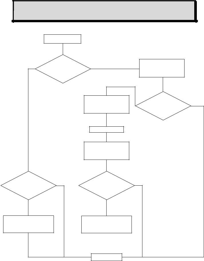
BLOCK DIAGRAM 1 |
NORMAL CYCLE WITH MANUAL CLEARING |
|
START |
|
|
|
No |
Threshold |
Yes |
Illumination of flashing |
|
exceeded |
|
|||
|
|
alarm LED |
|
|
|
|
|
|
|
|
|
Yes |
|
|
|
|
Illumination of flashing |
Time T1 |
No |
|
|
alarm LED |
exceeded |
|
|
|
|
||
|
|
After T2 time |
|
|
|
|
Relay engaged |
|
|
|
|
Buzzer engaged |
|
|
Alarm |
No |
Alarm |
No |
|
acknowledged |
acknowledged |
|
||
|
|
|
||
Yes |
|
Yes |
|
|
LED extinguished |
|
LED steady mode |
|
|
Relay disengaged |
|
Buzzer stopped |
|
|
Buzzer stopped |
|
|
|
|
END
22
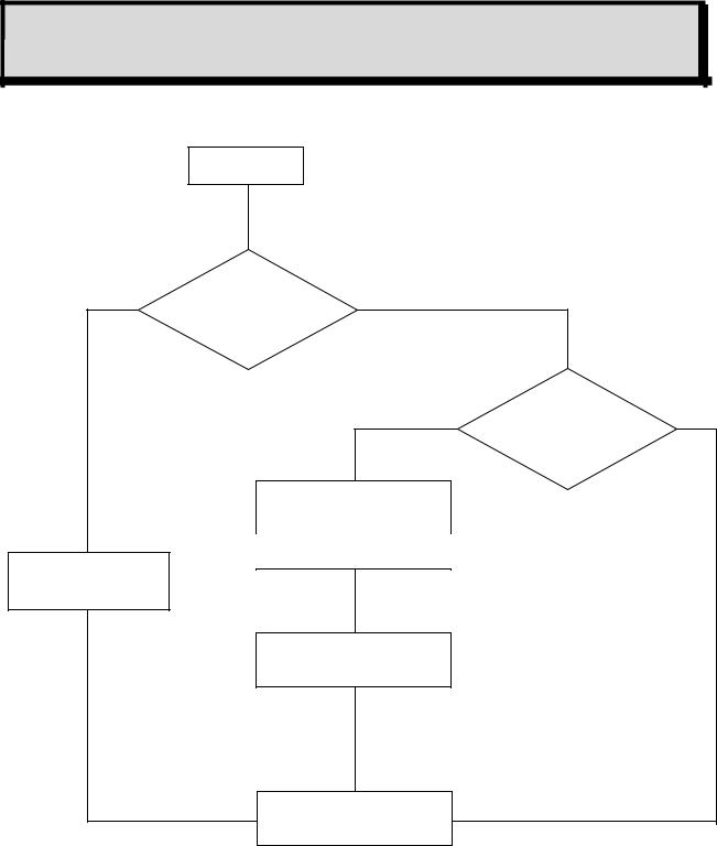
BLOCK DIAGRAM 2 |
NORMAL CYCLE WITH AUTOMATIC CLEARING |
|
START |
|
|
No |
Threshold |
Yes |
|
exceeded |
|
|
|
|
|
|
|
|
Yes |
Time T1 |
No |
|
exceeded |
||
|
|
|
|
|
Alarm LED illuminated |
|
|
|
in steady mode |
|
|
|
After T2 time |
|
|
LED extinguished |
|
|
|
Relay disengaged |
|
|
|
|
Relay engaged |
|
|
|
Buzzer engaged |
|
|
|
END |
|
|
23
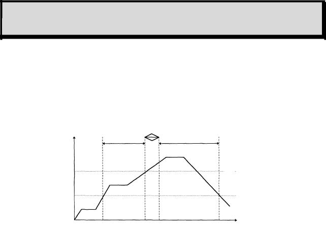
BLOCK DIAGRAM 3 |
PARKING CYCLE |
Alarm 3 operates in the same way as the normal cycle.
The times defined for alarms 1 and 2 (time delays) are, in this case, used to define the minimum operating time for each relay.
t AL1 |
tR1 R2 |
t AL2 |
Threshold AL2
Threshold AL1
Starting of |
Stopping |
Starting of |
Stopping of |
relay R1 |
of relay R1 |
relay R2 |
relay R2 |
|
|
min. |
tAL1 |
Min. operating time for alarm 1 |
t1 |
|
(defined for each channel) |
|
tAL2 |
Min. operating time for alarm 2 |
t2 |
|
(defined for each channel) |
|
tR1 R2 |
Switching time from relay 1 to relay 2 |
tR1 & R2 |
|
(defined for the whole unit) |
|
|
|
|
24

3.3.4. Fault thresholds
Processing of detector faults
Each channel detects the following faults.
For toxic and explosive gas detectors:
-line interrupted (0 mA),
-line short-circuited or excessive consumption,
-negative offset (more than 20% of measuring scale),
-line in calibration mode (2 mA) (if confirmed by programming).
For detectors of the explosive gas type (4-20 mA and 340 mA) in normal mode and if the measurement is greater than 100% of the measuring scale, there are the following immediate results:
-Display: SUP
-The relays are actuated if the thresholds are reached.
-The general fault relay is actuated.
-The 4-20 mA output of the channel is greater than 20 mA.
-ALl these states are memorized and the only way of acknowledging them is to switch off the channel and then restart it.
Faults are valid after a preprogrammed time (in the same way as alarms).
FAULT BLOCK DIAGRAM
START
Wait until the fault has been present for at least 5 seconds.
The relays are locked in their current state. The common fault relay is engaged.
The buzzer is engaged.
The channel fault LED is illuminated. * 1 mA is sent on the 4-20 mA output.
END
* The LED is extinguished as soon a the fault disappears.
25

3.3.5. Measuring unit
One minute after starting up, and if no test action is performed on the keypad, the unit successively scans all the channels in service and displays the measured values.
Examples of display
Channel 1 x x LEL CH4
OR
Channel 2 x x x ppm CO
-Each channel is interrogated for 10 seconds.
-The user can interrogate a channel manually by selecting that channel with the + and - keys to obtain a manual display for one minute.
-The user can return to normal cyclic scanning during that one-minute period by simultaneously pressing the + and - keys. The display panel then shows alternating displays, three times in succession:
For example:
Channel 5 x x x ppm CO
then
normal scan x x x ppm CO
26
4.UTILIZATION
4.1.List and functions of the various items of “USER” equipment for programming and calibration of the unit
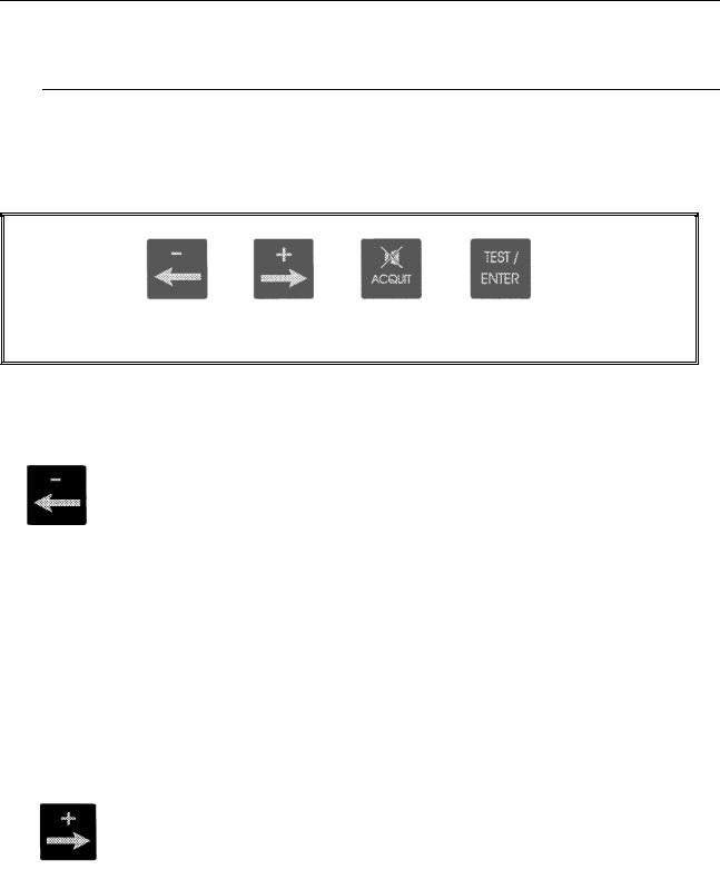
4.1.1. Keypad (see Figures 26 and 4)
This is equipped with four touch keys accessible without opening and swivelling the MX52 unit’s
FRONT panel or opening and swivelling the FRONT panel for maintenance.
Item D, Fig. 26
NORMAL MODE
-Manual display of previous channel
-Combined with the “PLUS” key to restart the channels automatic display cycle.
MAINTENANCE MODE
-Manual display of previous channel
-Decrease value, threshold, etc.
-Display of previous choice (onoff, etc.)
-NO
NORMAL MODE
-Manual display of next channel
-Combined with the “MINUS” key to restart the channels automatic display cycle.
MAINTENANCE MODE
-Manual display of next menu
-Increase value, threshold, etc
-Display of next chooice (onoff, etc)
-YES
27

-“Audio and visual” or “audio” clearing of an alarm
-Exit from a current menu
-Start a self-test manually
-VALIDATE
4.1.2.Maintenance keys
PROGRAMMING key (item B, Fig. 26): accessible after opening and swivelling the front panel.
-Combined with the “-” key to go back in a menu.
-To quit normal display mode and access the various menus (see block diagram of the various menus).
-To scroll through a menu.
CALIBRATION key (item C, Fig. 26): accessible after opening and swivelling the front panel.
-To set a channel to CALIBRATION mode.
-To quit that mode.
4.1.3. Potentiometers
On the FRONT circuit, each measuring channel has four potentiometers (item E in Figures 26 and 27). These are accessible by opening and swivelling the FRONT panel of the MX52 unit and are laid out as follows (see Fig. 27):
TOP (item A) |
1 detector ZERO potentiometer |
|
1 detector sensitivity potentiometer |
BOTTOM (item B) |
1 potentiometer 4 mA / current output |
|
1 potentiometer 20 mA / current output (for full scale) |
28

4.2. Menus
4.2.1. The various menus and their functions
The MX52 unit has five menus that are accessed by pressing the “Programming” key (item B, Fig.
26).
These five menus are as follows:
DESIGNATION |
FUNCTION |
“CHANNEL” programming |
- To program the whole configuration of a measuring |
|
channel (ON/OFF, range, alarm thresholds, etc.) |
“SIMULATION” programming |
- To artificially vary a channel measurement on: |
|
- the display panel, |
|
- the 4-20 mA current output. |
|
- To trigger the alarms (LED and relays) at the same |
|
time. |
“CHANNEL COPY” programming |
- To copy the complete programming from one channel |
|
to another (time saving) |
“UNIT” programming |
- To program the whole configuration of the MX52 unit |
|
(language, slave number, etc.). |
“UPLOADING” programming |
- To transfer data, measurements and events, etc., from |
|
the unit to a computer via the MX52 unit’s RS 485 / J |
|
BUS output. |
|
|
4.2.2. Block diagram of the scrolling of the various menus
It is easy to use these various menus by means of the keys on the keypad and the “Programming” key (items B and D, Fig. 26).
Detailed flow diagrams of the menu scrolling function and of each menu are given on the following pages.
29
 Loading...