

Page 1

User Manual
Surveyor 4B
Référence : NPS4BGB
Révision : E.0
The Fixed Gas Detection Experts
Page 2

ii
Surveyor 4B
User Manual
Copyright November 2018 by Oldham S.A.S.
All rights reserved. The reproduction of all or any section of this document in
any form whatsoever without the written permission of Oldham S.A.S. is
forbidden.
The information contained in this manual is accurate to our knowledge.
As a result of continuous research and development, the specifications of this
product may be modified at any time without prior notice.
Oldham S.A.S.
Rue Orfila
Z.I. Est – CS 20417
62027 ARRAS Cedex
Tel.: +33 (0)3 21 60 80 80
Fax: +33 (0)3 21 60 80 00
Website: https://gasdetection.3M.com
Page 3

Table of contents
iii
Table of contents
Chapter 1│ General Information ..................................................... 1
User Manual ................................ ................................................................ 1
Symbols used .............................................................................................. 1
Safety Instructions ....................................................................................... 2
Important Information .................................................................................. 2
Liability Limits .............................................................................................. 2
Warranty ...................................................................................................... 2
Chapter 2│ Description ................................................................... 3
Chapter 3│ Mounting of the SURVEYOR 4B ................................... 5
Chapter 4│ Connections ................................................................. 7
Alternative power supply.............................................................................. 7
DC power supply ......................................................................................... 8
Explosimetric detectors ............................................................................... 8
External components ................................................................................... 9
Examples of installation ............................................................................. 11
Chapter 5│ Operating instructions ............................................... 13
Switching on ................................ .............................................................. 13
Switching off ................................ .............................................................. 13
Alarms ....................................................................................................... 13
Chapter 6│ Technical specifications ............................................ 21
Chapter 7│ Disposal ...................................................................... 23
Chapter 8│ Main Part Numbers ..................................................... 25
Chapter 9│ Maintenance ............................................................... 27
Fuse replacement ...................................................................................... 27
Chapter 10│ Certificate of Compliance .......................................... 29
Page 4

iv
Surveyor 4B
User Manual
Page 5
1 - General Information 1
Chapter 1│ General Information
User Manual
The instructions given in this manual must be read thoroughly before
installation and start-up, particularly those concerning the points related to the
safety of the end-user. This user manual must be made available to every
person involved in the activation, use, maintenance, and repair of the unit.
The information, technical data, and diagrams contained in this manual are
based on the information that is available at a given time. In case of doubt,
contact Oldham for additional information.
The aim of this manual is to supply simple and accurate information to the
user. Oldham cannot be held liable for any misinterpretations in the reading of
this manual. In spite of our efforts to produce an error-free manual, it may
nonetheless contain some unintentional technical inaccuracies.
In the client’s interest, Oldham reserves the right to modify the technical
characteristics of its equipment to increase their performance without prior
notice.
The present instructions and their content are the inalienable property of
Oldham.
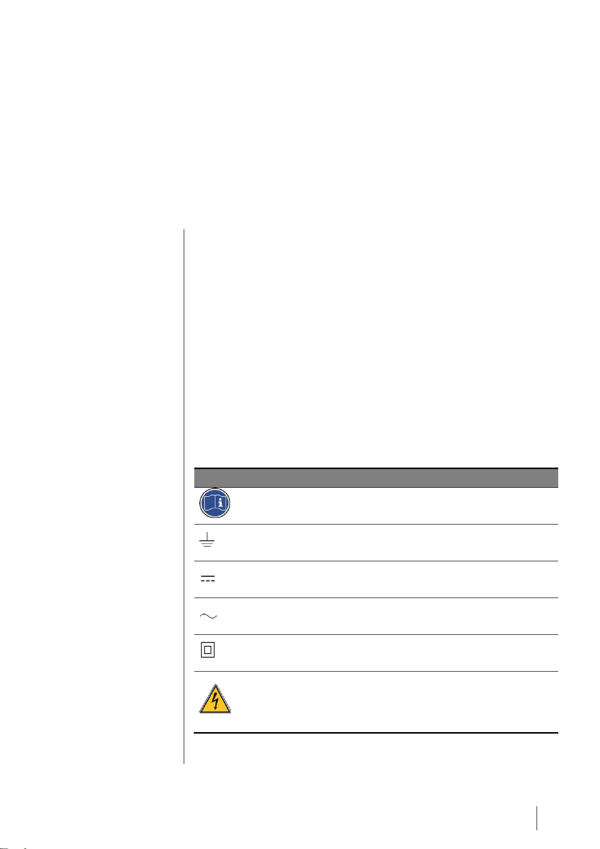
Symbols used
Icon
Significance
This symbol indicates useful additional information.
This symbol indicates:
Earth ground connection.
This symbol indicates:
DC voltage
This symbol indicates:
AC voltage
This symbol indicates:
Double insulated
This symbol denotes:
Attention! In the present mode of use, failure to adhere to the
instructions preceded by this symbol can result in a risk of
electric shock and/or death.
Page 6
2
Surveyor 4B
User Manual
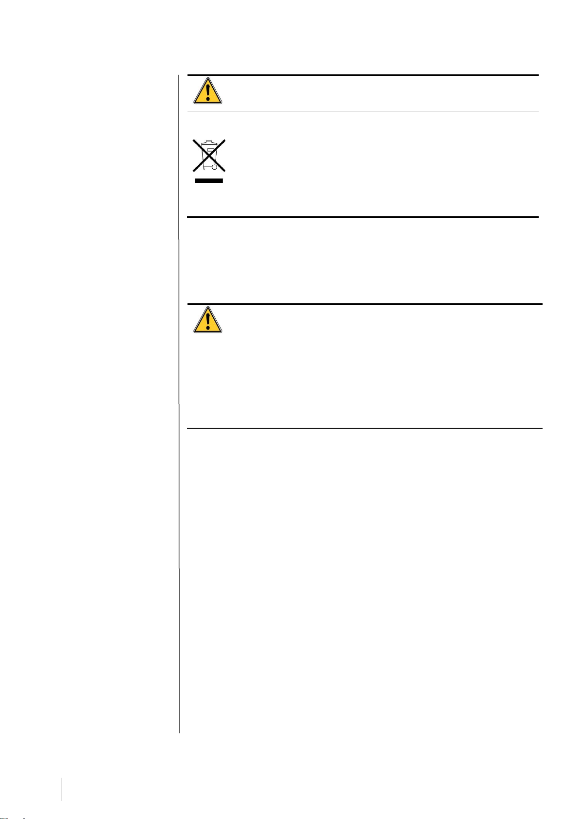
This symbol indicates:
You must refer to the instructions.
European Union (and EEA) only. This symbol indicates that this
product must not be discarded with household waste, as per the
EEA directive (2002/96/EC) and your own national regulations.
This product must be disposed of at a collection point that is
reserved for this purpose, for example, an official site for the
collection of electrical and electronic equipment (EEE) in view of
their recycling, or a point of exchange for authorized products that
is accessible when you acquire a new product of the same type.
Safety Instructions
Labels intended to remind you of the principal precautions of use have been
placed on the unit in the form of pictograms. These labels are considered an
integral part of the unit. If a label falls off or becomes illegible, please ensure it
is replaced. The significance of the labels is detailed below.
The installation and electrical connections must be carried out by
qualified personnel according to the instructions of the manufacturer
and the standards of the competent authorities.
Failure to adhere to the instructions can have serious consequences
on the safety of persons. Please be extremely rigorous as regards
electricity and assembly (coupling, network connections).
Cables with an operating temperature of 60°C minimum (140 °F)
must be used because the temperature inside the controller can
reach 65°C (149 °F).
Important Information
The modification of the material and the use of parts of an unspecified origin
shall entail the cancellation of any form of warranty.
The use of the unit has been projected for the applications specified in the
technical characteristics. Exceeding the indicated values cannot in any case
be authorized.
Liability Limits
Neither Oldham nor any other associated company under any circumstances
can be held liable for any damage, including, without limitations, damages for
loss or interruption of manufacture, loss of information, defect of the Surveyor
4B controller, injuries, loss of time, financial or material loss, or any direct or
indirect consequence of loss occurring in the context of the use or
impossibility of use of the product, even in the event that Oldham has been
informed of such damage.
Warranty
Under normal conditions of use and on return to the factory, parts and
workmanship carry a one year warranty, excluding consumables such as
backup power supplies, audio and visible alarms, etc.
Page 7

2 – Description
3
Chapter 2│ Description
This controller is intended for the continuous measurement and control of the
gases present in the atmosphere.
The Surveyor 4B is intended for indoor use only and shall be installed in
premises without explosive atmospheres.
The central controller is intended for use in areas that meet the Class II
requirements for overvoltage and degree of pollution 2. Surveyor 4B is Class
II equipment.
Surveyor 4B is equipped with a small "NORMAL" box (58 x 105 x 90 mm). It
can be snap-fastened onto a standard symmetrical DIN rail and should
imperatively be integrated in a closed electrical equipment cabinet.
Page 8
4
Surveyor 4B
User Manual
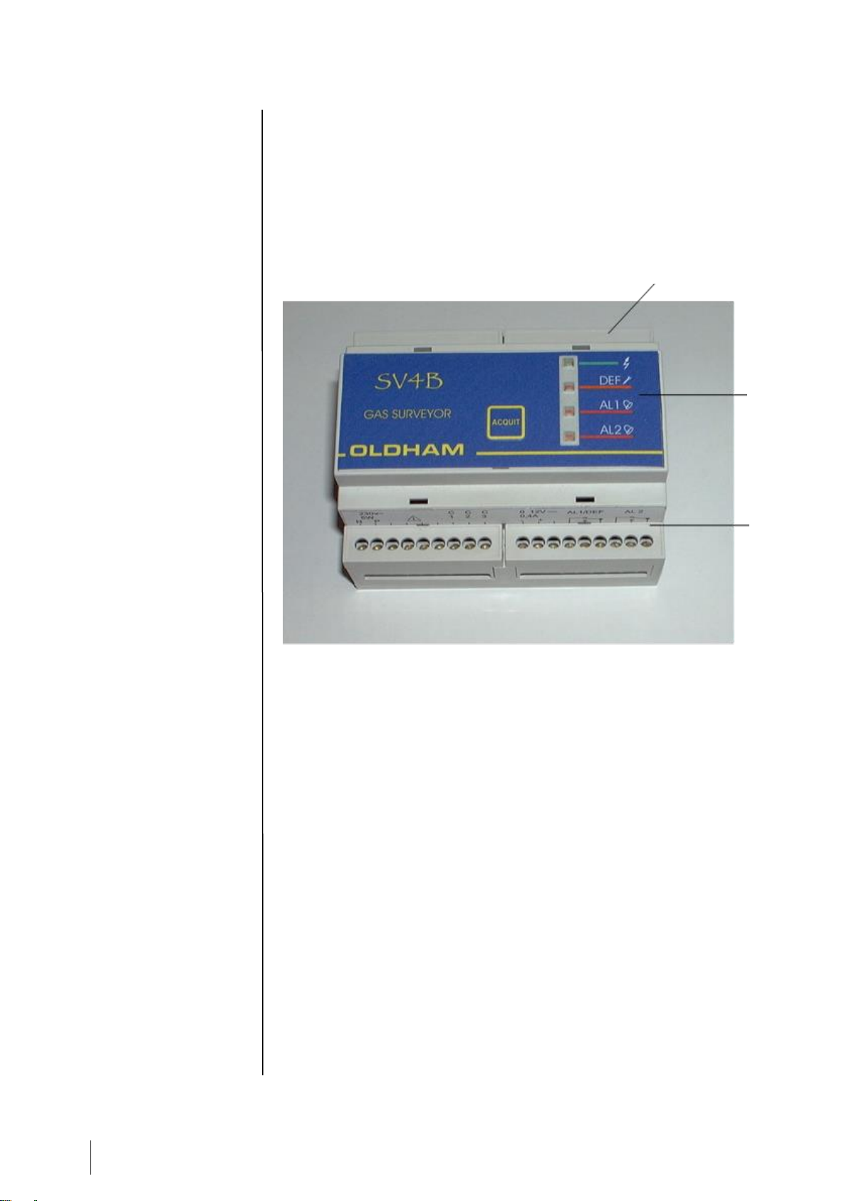
The components used in operation are located on the front of the appliance:
- adjustments and tests on the top (Item 1, Figure 1),
- indicator lights on the FRONT face (Item 2,Figure 1),
- connections at the bottom (Item 3, Figure 1).
Figure 1
Item 1
Item 2
Item
Item 3
Page 9

3 - Mounting of the SURVEYOR 4B
5
Chapter 3│ Mounting of the SURVEYOR 4B
The surveyor 4B appliance fitted on its symmetrical DIN rail must be
installed in a closed electrical equipment cabinet.
A space of 100 mm is necessary around of the Surveyor 4B.
The Surveyor 4B should preferably be located in a monitored
location (such as a guardhouse, control room or instrumentation
room).
Page 10

6
Surveyor 4B
User Manual
Page 11

5 - Connections 7
Chapter 4│ Connections
The Surveyor 4B does not have a start/stop switch.
Certain voltage levels are capable of causing serious injuries or even
death. It is advised to install the material and cabling before applying
live voltage.
Since an incorrect or poor installation may cause measurement
errors or system failures, it is necessary to strictly follow all the
instructions in this manual in order to guarantee the proper operation
of the system.
Cables with an operating temperature of 60°C minimum (140 °F)
must be used because the temperature inside the controller can
reach 65°C (149 °F).
The electrical connections must be carried out by qualified personnel in
compliance with the different directives in force in the country of installation.
The nature of the current and line voltage must be checked. The line voltage
must match the voltage specified on the plate fitted on the Surveyor 4B. The
voltage is configured in the factory.
The wires to be connected to the Surveyor 4B must have a minimum cross
section of 1.5 mm².
The Surveyor 4B appliance can be supplied with either 230 Vac1 or 12 Vcc2.
Alternative power supply
230 volt AC power supply
The Surveyor 4B must be protected on the upstream side by a two-pole earth
leakage circuit breaker (1A) installed near the Surveyor 4B and is considered
as main cut-off device.
The response curve must be of type D.
The mains power supply must be wired on the two points marked N (Neutral)
and P (Phase) on the Surveyor 4B terminal block (see Figure 2, Item 1).
The wires to be connected to the Surveyor 4B must have a minimum cross
section of 1.5 mm²
Power consumption: 5.8 W max. (detector connected).
1
from 207 to 253 Vac
2
from 11.5 to 14 Vdc
Page 12

8
Surveyor 4B
User Manual
DC power supply
12-volt power supply
The 12 volt power supply can be connected to the points marked 0 and 12 V
on the Surveyor 4B terminal block (see Figure 2, Item2).
The Surveyor 4B must be protected on the upstream side by a fuse (630mA)
with time-delay.
The cable must have a minimum cross section of 1.5 mm².
Power consumption: 5.8 W max. (detector connected).
Explosimetric detectors
• Only explosimetric detectors of the "bridge" type can be connected to
the SV 4B.
• Surveyor 4B and the detector are connected together b y a shielded
cable with three active conductors. The shielded cable is to be
connected to the earth to EMC constraints at one end only.
• Terminals C1, C2 and C3 of Surveyor 4B and the detector are to be
connected in opposite mode (Figure 3).
Figure 3 : Detector connections
Figure 2 : power supply connections
Item 1
Item 2
Page 13

5 - Connections 9
• The maximum loop resistance is 1.4 ohms.
For example: the maximum distance between Surveyor 4B and the detector
will be 40 m with conductors with a cross section of 1.5 mm².
External components
Surveyor 4B is equipped with the following two relays:
• Relay 1 (REL 1), which is in mode, corresponds to the first gas alarm
threshold and to the "FAULT" alarm.
This relay is equipped with SPDT contacts available on the SV 4B
terminal block (Item 3, Figure 4).
• Relay 2 (REL 2), which is "negative safety" mode, corresponds to the
second gas threshold only. This relay is also equipped with SPDT
contacts available on the SV 4B terminal block (item 4, Figure 4).
• These both relays could be configured in positive and negative
security (programmation by welding slots on the printed circuit board:
made only by OLDHAM or a skilled personal).
N.B. : The relay contacts are dry contacts, corresponding to the appliance
without power supply.
3
2
1
Detector terminal
Item 3
Item 4
Figure 4 : relays terminals
Page 14

10
Surveyor 4B
User Manual
Caution: The high-power solenoid valves cannot be directly remote
controlled
3
. A power relay is required.
3
The maximum current through the relay contacts will be 2 A and the maximum voltage will be
250 Vac ou 30 Vdc.
Page 15

5 - Connections
11
Examples of installation
Example of installation set up of a SV 4B with TWO OLC 10 TWIN
detectors
* Breaking capacity of rating relays switch contact: 2A / 250Vca - 30Vdc
Important :
The relay's contacts are shown on the SV 4B label, unit switch off.
The AL1/ DEF relays are normally energized and the AL2 relay is
unenergized.
Figure 5 Example of installation set up of a SV 4B with TWO OLC 10 TWIN detectors
Page 16

12
Surveyor 4B
User Manual
Example of installation set up of a SV 4B with a single
detector
* Breaking capacity of rating relays switch contact : 2A / 250Vca – 30Vcc
Important :
The relay's contacts are shown on the SV 4B label, unit switch off.
The AL1/ DEF relays are normally energized and the AL2 relay is
unenergized.
Figure 6: Exemple d'installation d'un Surveyor 4B avec un capteur
Page 17

5 - Operating instructions
13
Chapter 5│ Operating instructions
Switching on
It is assumed that all the necessary connections have been made and that the
whole installation complies with the standards currently in force.
As soon as the SV 4B is supplied with power, it is ready to use and the
GREEN light-emitting diode lights up (rep 1, Figure 7).
Relay 1 is operated ("positive safety" position).
Switching off
The SV 4B is switched off by cutting off the power supply on an electrical
equipment cabinet.
Alarms
GAS alarm
The SV 4B has two adjustable GAS alarm thresholds but the second threshold
(AL 2) must be twice the first (AL 1).
Therefore, the red light-emitting diodes "AL1" and "AL2" (rep 3, Figure 7)
come on as soon as the alarm thresholds are exceeded (time delay of 7
seconds): LED flashing. The audio alarm (buzzer) is activated and the
corresponding relays are tripped.
Figure 7
item 4
item 1
item 2
item 3
Page 18

14
Surveyor 4B
User Manual
FAULT alarms
The SV 4B is equipped with a fault alarm (visual alarm (rep 2, Figure 7), audio
alarm and relay 1) which is activated in the following cases:
• One or more wires of the telemetry line interrupted
• One or more wires of the telemetry line short-circuited or with
excessive power consumption.
NB : The ALARM LEDs may also be activated depending on the
circumstances of the interruption or the short circuit.
Adjustments
The operations and adjustments described in this chapter must
be performed by authorized personnel only as they can affect the
appliance's reliability in detection.
Gas detectors are safety devices. OLDHAM recommends the regular testing
of fixed gas detection installations. This type of test consists of injecting the
calibration gas into the detector at a sufficient concentration to activate the
pre-set alarms. It is to be understood that this test is in no way a replacement
for a detector calibration.
The frequency of gas tests depends on the industrial application where the
detector is in use. Frequent inspections should be made in the months
following the commissioning of the installation, and should then become more
widely spaced provided that no significant deviation is observed. If a detector
should fail to react in contact with the gas, calibration is essential. The
frequency of calibrations shall be appropriate according to the results of the
tests (humidity, temperature, dust, etc.); however, it must not exceed one
year.
The general manager should put safety procedures in place on-site. OLDHAM
cannot be held responsible for their enforcement.
Page 19

5 - Operating instructions
15
Adjusting the "gas alarm" thresholds
Using a "reference gas kit" (gas cylinder + pressure regulator, etc.), inject the
reference gas with a content level higher than the first threshold desired. (For
example, threshold 1 will be 20% LEL, so a minimum of 25% LEL should be
injected).
Adjust the alarm potentiometer (rep 1, Figure 8) to trigger the first threshold
(AL1): the red LED (AL1) flashes (for 7 seconds) and then remains on in
steady mode, trip the corresponding alarm relay.
If you stop at this point, alarm 2 will be set to twice the level of alarm 1.
If you continue until alarm 2 is triggered: alarm 1 will be set to half the level of
alarm 2.
If you wish to lock the alarm relays (inhibiting the relays) during these alarm
threshold adjustments: set the maintenance switch to the high position (item
2, Figure 8).
Figure 8
Maintenance
( ↑ up)
Normal
item 3
item 1
item 2
item 4
MV
item 5
Page 20

16
Surveyor 4B
User Manual
When the adjustments have been made, do not forget to place
the switch back in its normal position.
Terminal posts item 3, Figure 8) are used to connect up a voltmeter for the
reading of a signal (in mV) corresponding to the content level of the injected
gas.
Then, using a rule of three, it is possible to calculate and adjust another signal
(in mV) for an alarm threshold (potentiometer: item 1, Figure 8) corresponding
to a different gas content level.
For example : when you inject 1% methane, you read 1,000 mV (for
instance).
If you set the alarm potentiometer to read 1,500 mV, the alarm is triggered at
1.5% methane.
Signal =
mV
mV
mVx
1500
1000
%11000
Or
Threshold (%) =
1% 1500
1000
15%
x mV
mV
.
Acknowledgement of gas alarms
A switch (item 4, Figure 8) is used to acknowledge gas alarms in manual
mode 4 or automatic mode 5
4
manuel : Manual mode: When a gas alarm is triggered, it must be cleared manually even if the
content level has fallen to zero (or to below the threshold). This is done by pressing the Ack. key
(item 5, Figure 8).
5
Automatic mode: When a gas alarm is triggered, it is cleared automatically as soon as the
content level falls below the alarm threshold.
Automatic ack.
( ↑ Up)
Manuel ack.
Page 21

5 - Operating instructions
17
As long as there is a high enough concentration of gas to
trigger an alarm, it is impossible to clear that alarm manually
(with the Ack. button).
Page 22

18
Surveyor 4B
User Manual
Adjusting the ZERO
- Necessary when a cell is replaced
- At least twice a year
- Connect a voltmeter to the two terminal posts provided for that purpose (MF
and MES), as shown below:
Figure 9
- Be sure to be in pure atmosphere (without gas) (If not, inject air)
- Adjust the ZERO (0 mV) with the potentiometer, item 1.Figure 9.
Checking the sensitivity
- Necessary when a cell is replaced.
- At least twice a year.
- Prepare the calibration kit and secure the gas input pipe to the detector.
- Adjust the flow rate of the reference gas6 to 60 l/h before injecting.
- Allow to stabilize for at least 10 seconds.
- Check that the alarm or alarms are triggered (as applicable 6) and carry out
the following procedure.
6
La valeur du gaz étalon sera supérieure au moins au premier seuil d'alarme.
item 1
item 2
MV
Page 23

5 - Operating instructions
19
Page 24

20
Surveyor 4B
User Manual
Replacing the fuse
It is mandatory that spare parts must be guaranteed original
OLDHAM parts as, otherwise, the reliability of the equipment
could be adversely affected.
The fuse (Figure 10, item 1) must be replaced by qualified personnel only.
The fuse is, and must be, in compliance with CEI 127, with time-delay, low
breaking capacity and a voltage of 250 V ~.
- Fuse 5x20- T125 mA 250 V- OLDHAM reference = 6154701
Figure 10
item 1
Page 25

6 – Technical specifications
21
Chapter 6│ Technical specifications
Manufacturer
OLDHAM
Type
SURVEYOR 4 B
Function
Control station for explosive gas detectors
Capacity
1 measurement chanel
1 detector type CEX 300 or OLC10/100 or 2
OLC 10Twin detectors
Measurement
Measurement
Display unit
Continious
None
Visual alarms
Failure: yellow
Gas, 1st threshold: red
Gas, 2nd threshold: red
Audio alarm
Integrated
Alarm Acknowledgement
Manual ou automatic
Electric power supplies
Alternative
Continue
230 VCA (207 à 253 V) – 50Hz
Accepts category II transient overvoltages
and pollution degree 2
12 VCC (11.5 à 14 V)
Power consumption
5.8 W (detector connected) @230Vac
0.4A (detector connected) @12 Vdc
Electrical protection
Fuse
Relays
Relay 1
Relay 2
Common to gas (alarm 1) and fault
Gas alarm 2
Contact
SPDT, relay 1 (positive safety)
SPDT, relay 2
Max. breaking capacity
2A sous 250Vca ou 30Vcc
Measuring line
Cable
Maximum line length
Maximum loop resistance
3 conductors
40 m (with conductor 1.5 mm²)
1.4 ohms
Mounting
On symmetrical DIN rail and into a
closed cabinet
Miscellaneous
Technology
Mains visual indicator
Housing
Warranty
SMC (surface mounted component)
Green LED
NORYL
1 year
Dimensions
58 x 105 x 90 mm
Weight
0.360 kg
Cable inlets/outlets
Screw type terminal block
Ingress Protection
IP 20
Mecanical protection
IK 08
Operating conditions
Ambient temperature
Relative humidity
Altitude
+ 10 °C to + 45 °C
5 % to 95 % non-condensed
≤2000m
Page 26

22
Surveyor 4B
User Manual
Page 27

7 – Disposal
23
Chapter 7│ Disposal
Concerning the conservation, of the protection and the improvement of the
quality of the environment, as well as for the protection of the health of the
persons and the careful and rational use of natural resources, SV 4B has to
be the object of a selective collection for the elec tronic equipments and
cannot be scrapped with the normal domestic waste. The user
thus has the obligation to separate the SV 4B of the other waste
so as to guarantee that it is recycled in a sure way at the
environmental level. For more details of the existing sites of
collection, contact the local administration or the distributor of this
product.
Page 28

24
Surveyor 4B
User Manual
Page 29

8 – Main Part Numbers
25
Chapter 8│ Main Part Numbers
Désignation
Reference
Surveyor 4B controller for 340mA wheatstone bridge
sensor
6 514 807
Fuse 5x20 - T125 mA 250 V
6 154 701
Page 30

26
Surveyor 4B
User Manual
Page 31

9 – Maintenance
27
Chapter 9│ Maintenance
Fuse replacement
Fuse replacement should only be performed by qualified personnel
and power must be first switched off.
Fuses shall comply with IEC 60127 standard (time-delay fuse, low breaking
capacity, 250Vac). Please see Chapter 8│.
Oldham does not allow any other repairs than those listed here
above.
Page 32

28
Surveyor 4B
Manuel utilisateur
Page 33

10 – Certificate of Compliance
29
Chapter 10│ Certificate of Compliance
The document hereafter (1 page) reproduces the EU declaration of
conformity.
Page 34

30
Surveyor 4B
Manuel utilisateur
Page 35

Page 36

10 – Certificate of Compliance
32
The Fixed Gas Detection Experts
EUROPEAN PLANT AND OFFICES
Z.I. Est – rue Orfila CS 20417 – 62027 ARRAS Cedex FRANCE
Tél.: +33 (0)3 21 60 80 80 – Fax: +33 (0)3 21 60 80 00
Web site: https://gasdetection.3M.com
AMERICAS
Tel : +1-713-559-9280
Fax : +1-281-292-2860
americas@oldhamgas.com
ASIA PACIFIC
Tel : +86-21-3127-6373
Fax : +86-21-3127-6365
sales@oldhamgas.com
EUROPE
Tel : +33-321-608-080
Fax : +33-321-608-000
info@oldhamgas.com
gasandflamedetection@mmm.com
 Loading...