

Page 1

TRANSMITTER DETECTORS
FOR EXPLOSIVE GASES
TECHNICAL MANUAL
Ref.:
CD0000
4
Code: 06_MT_OLCTIR_GB_24_11_06
Page 2

3
GAS DETECTION
We are delighted that you have chosen an ISC/OLDHAM instrument and would like to thank you for your
choice.
We have taken all the necessary measures to ensure that your instrument provides total satisfaction.
Now it is important to read this document carefully.
EEXXTTEENNTT OOFF RREESSPPOONNSSIIBBIILLIITTYY
* ISC/OLDHAM declines its responsibility towards any person for material damage, physical injury or death
resulting wholly or partly from inappropriate use, installation or storage of its equipment resulting from failure to
observe instructions and warnings and/or standards and regulations in force.
* ISC/OLDHAM neither supports nor authorises any company, physical or moral person to assume responsibility on
behalf of ISC/OLDHAM , even if it is involved in the sale of ISC/OLDHAM products.
* ISC/OLDHAM cannot be held responsible for direct or indirect damage or be required to pay direct or indirect
compensation resulting from the sale or use of any of its products IF THESE PRODUCTS HAVE NOT BEEN
DEFINED AND CHOSEN BY ISC/OLDHAM FOR THEIR SPECIFIC USE.
CCLLAAUUSSEESS CCOONNCCEERRNNIINNGG PPRROOPPEERRTTYY
* Drawings, plans, specifications and information included in this document contain confidential information that is
the property of I SC/OLDHAM
* None of this information may be reproduced, copied, divulged or translated, by physical, electronic or any other
means, nor used as the basis for the manufacture or sale of ISC/OLDHAM equipment or for any other reasons
without prior consent from ISC/OLDHAM
WWAARRNNIINNGGSS
* This document is not contractually binding. In the interests of its customers, ISC/OLDHAM reserves to modify the
technical specifications of its equipment without notice, in order to improve its performance.
* READ THIS MANUAL CAREFULLY BEFORE FIRST USE OF THE EQUIPMENT: this manual must be
read by any person who is or will be responsible for using, maintaining or repairing this equipment.
* This equipment will only provide the announced performance levels if it is used, maintained and repaired
according to ISC/OLDHAM directives, by ISC/OLDHAM personnel or by personnel approved by
ISC/OLDHAM
GGUUAARRAANNTTEEEE
2 years guarantee in normal conditions of use on parts and technical labour, return in our workshops, excluding
consumables (sensors, filters, etc.)
Page 3
4
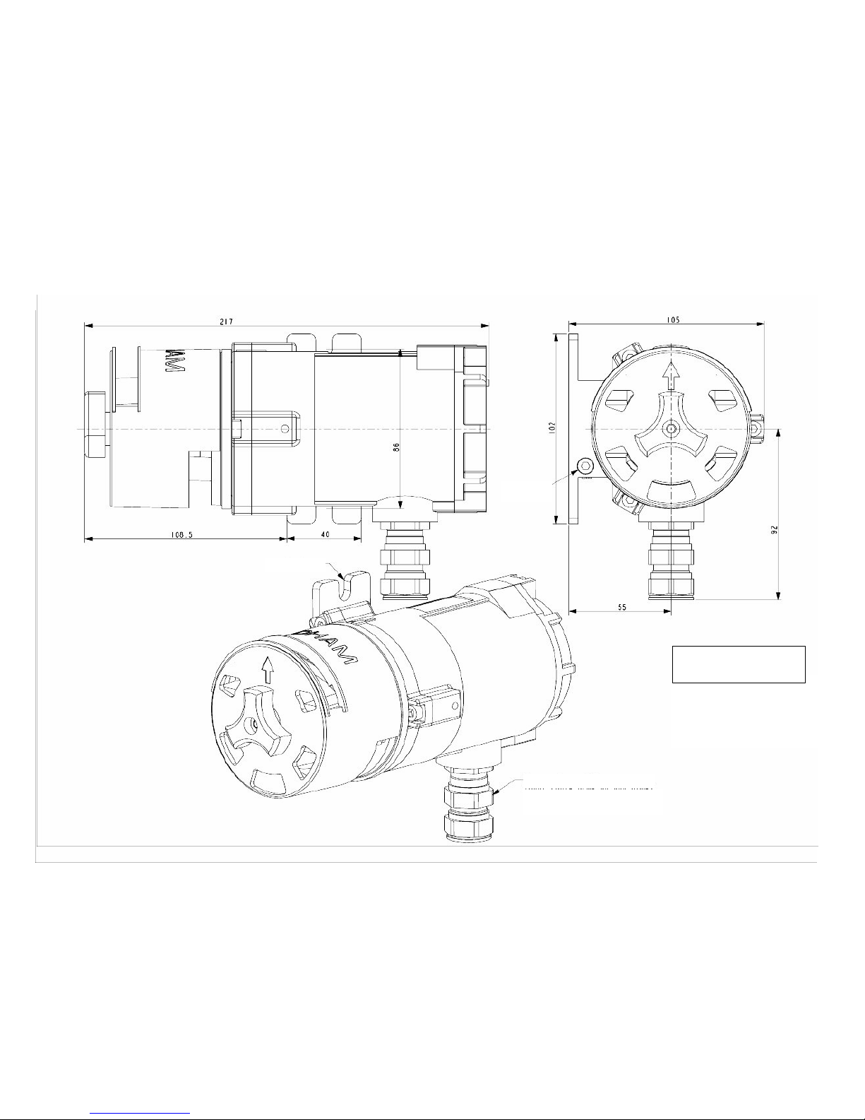
OOLLCCTT IIRR ""EE"" vveerrssiioonn
wwiitthh aannttii--ssppllaasshh
ccoovveerr
Figure 1
Earth screw
(for armoured or non-armoured
cable)
Cable gland, M20
Fastening lug
Page 4
5
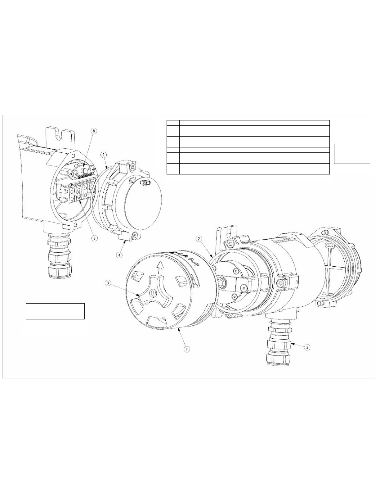
OOLLCCTT IIRR ""EE"" vveerrssiioonn
EExxppllooddeedd vviieeww
Figure 2
Option: non-
armoured cable
gland, ref 6343493
REF. QTY NAME OFSA REF
1 1 ANTI-SPLASH COVER 6124954
2 1 O-RING DIA. 65 x 3 6136242
3 1 LOCKING NUT, M5 6903376
4 1 "E" ENCLOSURE COVER 6123575
5 1 CABLE GLAND, M20, ARMOURED CABLE 6343489
5 1 CABLE GLAND, M20, NON-ARMOURED CABLE 6343493
6 1 EEx 2-PIN TERMINAL BLOCK 6152989
7 1 O-RING DIA. 69 x 2 6135036
8 1 IR SENSOR LED CARD 6451495
Page 5
6
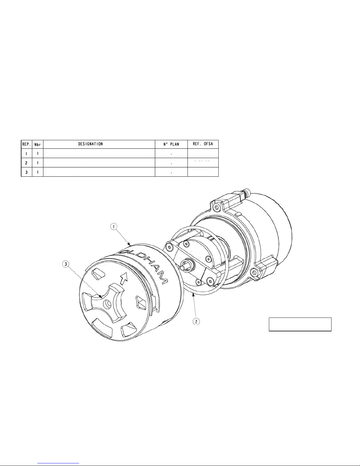
FFiigguurree 33
OOLLCCTT IIRR MM2255 vveerrssiioonn
EExxppllooddeedd vviieeww
ANTI-SPLASH COVER
O-RING, DIA. 66 x 3
LOCKING NUT M5
6313862
6136100
6903376
Page 6
7
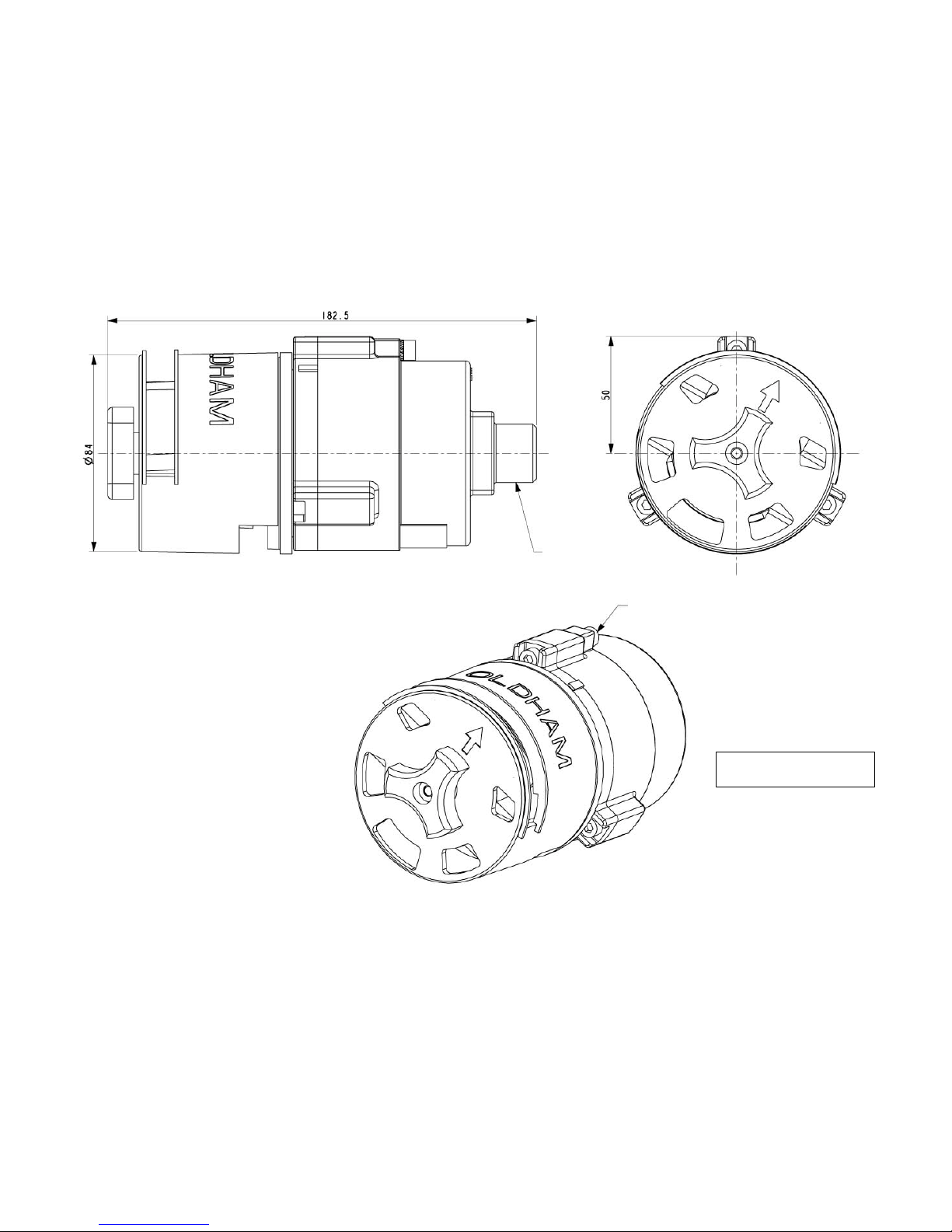
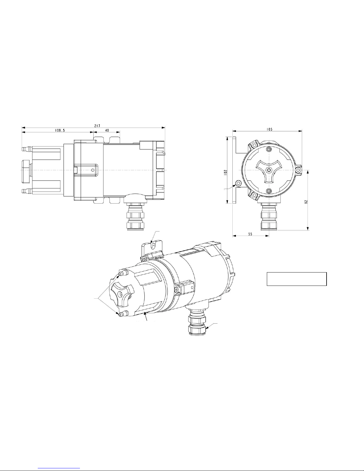
FFiigguurree 44
OOLLCCTT IIRR MM2255 vveerrssiioonn
wwiitthh aannttii--ssppllaasshh ccoovveerr
Earth screw
Thread: M25, pitch 1.5
Page 7
8
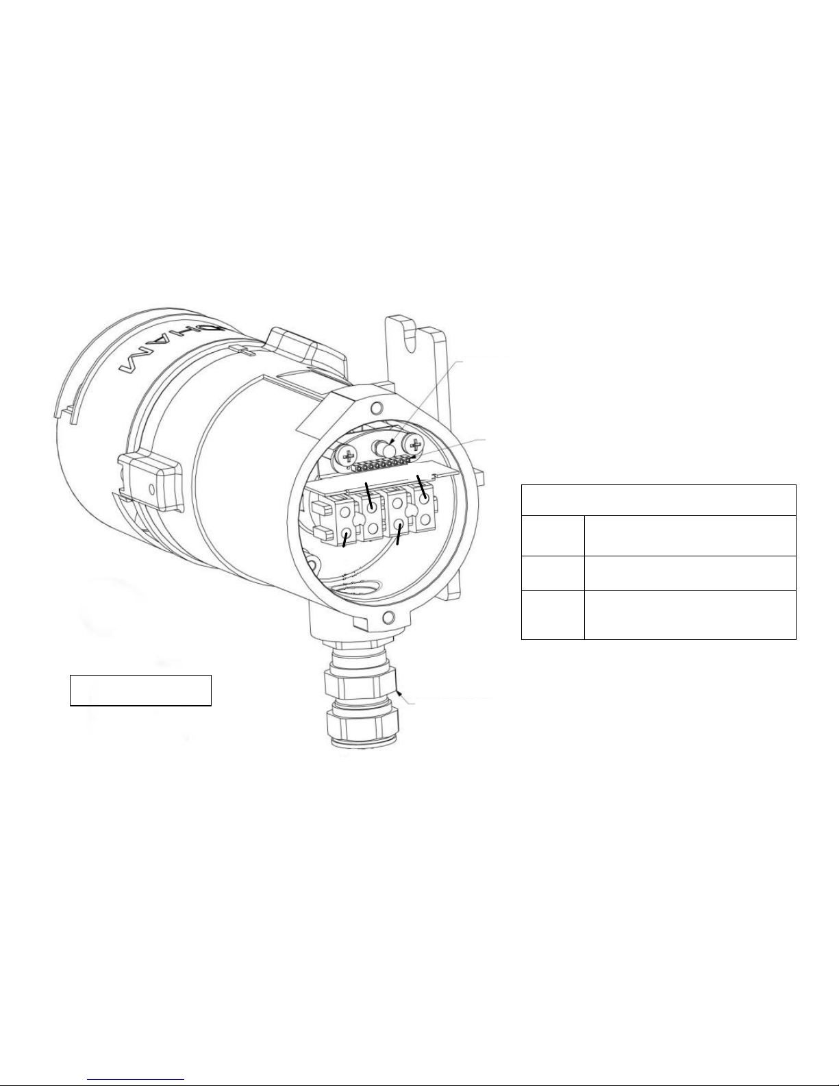
FFiigguurree 55
OOLLCCTT IIRR EE vveerrssiioonn
CCoonnnneeccttiioonn tteerrmmiinnaall
bblloocckk
OLCT IR connections
Iout
Output signal in mA (terminal 1
of ISC/OLDHAM central units)
0V
Power supply 0 V (terminal 2 of
ISC/OLDHAM central units)
+24VDC
Power supply + (terminal 3 of
ISC/OLDHAM central units)
Ser = service (do not use)
Iout
0V
+24VDC
Ser
(for armoured or non-armoured
cable)
Check LED
Magnetic receiver
Cable gland, M20
Page 8
9
/M25
FFiigguurree 66
OOLLCCTT IIRR EE vveerrssiioonn
wwiitthh ggaass cciirrccuullaattiioonn hheeaadd
((ccaalliibbrraattiioonn ppiippee))
GAS INLET AND
OUTLET
GAS CIRCULATION
HEAD
Earth screw
Fastening lug
Cable gland, M20
Page 9

10
FFiigguurree 77
OOLLCCTT IIRR MM2255 vveerrssiioonn
wwiitthh ggaass cciirrccuullaattiioonn hheeaadd
((ccaalliibbrraattiioonn ppiippee))
Thread: M25, pitch: 1.5
Earth screw
Page 10

11
Marking of electrical conductors
1 Output signal in mA (terminal 1 of
ISC/OLDHAM central units)
2 Electrical earth (terminal 2 of
ISC/OLDHAM central units)
3 + 24V DC power supply (terminal 3
of ISC/OLDHAM central units)
4 (service: output not used)
Figure 8
OLCT IR M25 version
Wiring
M25 nut + seal
Customer supply
EEx "e"
compartment
Earth screw
Thread M25, pitch 1.5
1 kO resistor supplied and wired by
ISC/OLDHAM
> or = 10 mm
EEx "d"
compartment
Page 11

12
FFiigguurree 99
FFaasstteenniinngg ssyysstteemm ffoorr OOLLCCTT IIRR
EE vveerrssiioonn wwiitthh aaddaappttoorr bbrraacckkeett
Bracket : 6132380
Page 12

13
CONTENTS
1. PRESENTATION.........................................................................................................................................................14
2. TECHNICAL CHARACTERISTICS .............................................................................................................15
2.1. Interference levels of common gases on the OLCT IR CH4 and HC. ............................... 16
3. INSTALLATION..........................................................................................................................................................17
3.1 Precautions......................................................................................................................... 17
3.2. Mechanical installation...................................................................................................... 17
3.3 Electrical installation......................................................................................................... 18
3.3.1. OLCT IR "E" Version................................................................................................ 18
3.3.2. OLCT IR M25 or other:............................................................................................. 18
4. FIRST START-UP.......................................................................................................................................................18
5. MAINTENANCE..........................................................................................................................................................18
5.1. Curative maintenance ........................................................................................................ 18
5.2. Periodic maintenance......................................................................................................... 19
5.3. Verification ........................................................................................................................ 19
5.4. Calibration procedure for OLCT IR "E" version: .............................................................. 19
5.5. Calibration procedure for OLCT IR M25 or other: ........................................................... 21
6. LIST OF OPTIONS AND REFERENCES...................................................................................................22
6.1. LIST OF ACCESSORIES ................................................................................................. 22
7. SPECIAL INSTRUCTIONS FOR USE IN EXPLOSIVE ATMOSPHERES........................23
8. MARKING:......................................................................................................................................................................24
8.1. For a detector of the type OLCT IR M25 or other, screw-on version:.............................. 24
8.2. For a detector of the type OLCT IR "E":........................................................................... 24
9. CERTIFICATE OF APPROVAL......................................................................................................................25
Page 13

14
11.. PPRREESSEENNTTAATTIIOONN
The OLCT IR gas detector is designed to measure explosive gases in the atmosphere. It is based on the
principle of optical detection of gases using the infrared band, giving it a very high level of detection reliability.
It uses a direct current power supply and delivers a standardised 4-20 mA current proportional to the measured
gas concentration. The "E" version of the OLCT IR has a local calibration device allowing it to be calibrated in an
ATEX zone without opening the case.
The OLCT IR detector can be used in atmospheres containing explosive gases and dusts and meets the essential
requirements of European Directive ATEX 94/9/EC.
Two different versions are available:
OLCT IR "E" version:
- Stand-alone version with an "e" (increased safety) enclosure fitted with:
- A fastening system,
- An M20 cable gland (1) as an option,
- A hazardous zone connection compartment for electrical connections in explosive zones (see Fig. 02),
- A calibration device using a magnet and a LED indicator.
(1) : M20 cable gland (ref. 6143506 + seal ref. 6136202), for cable with outer diameter of 8.5 to 16 mm and inner
diameter of 6 to 12 mm.
OLCT IR M25 version:
- This version can be fitted on a connection box via a standard straight or tapered pipe thread. In this case,
connections must be made in an enclosure that is also certified. The standard type is the OLCT IR M25
with M25 thread. Other types are available on request: for example, OLCT IR ½ NPT.
- Version fitted with a 5-wire output for electrical connections in a certified system designed for a specific
application (Fig. 08).
Note: In the remainder of this document, this version will be referred to as OLCT IR M25 or other.
For each version, there are two types of detector:
Methane (CH4) version:
- Optimised for the detection of methane, with a standard range of 0 to 100% LEL
HC version:
- Optimised for the detection of saturated hydrocarbons (propane, butane, pentane, hexane, etc.) with a
selectable standard range set in the factory: C3H8 – 0 to 100 % LEL
C4H10 – 0 to 100 % LEL, for example
Page 14

15
22.. TTEECCHHNNIICCAALL CCHHAARRAACCTTEERRIISSTTIICCSS
((11)
)
Detection principle Optical: Infrared absorption
Types of gas detected Methane, propane or butane for standard version (2)
Note: The type of gas detected is programmed by
ISC/OLDHAM in the factory
Standard measurement ranges 0 to 100 % LEL CH4, C3H8 or C4H10, 0 to 100% volume CH4
Accuracy ± 3% LEL or ± 5% of the indication
Stability from -25°C to +55°C and long-term Zero: ± 1 LEL
Gain: ± 5% LEL or ± 10% of the indication
Response time without protective cover
With protective cover
T50 < 7 seconds
T90 < 8 seconds
T50 < 10 seconds
T90 < 16 seconds
Power supply voltage at sensor terminals 16 to 30 VDC
Average power consumption 2.5 Watts nominal (maximum intermittent current = 500 mA)
Current output (signal)
Current source encoded from 0 to 25 mA (non-isolated)
4 to 20 mA linear current reserved for measurement
0 mA indicates an electronic fault or no power supply
An output of 1.5 mA indicates an optical fault, Temperature
outside limit
A 2 mA output indicates calibration mode
An output greater than 23 mA indicates a range overrun
Type of cable Screened, 3 active wires
Maximum resistance per conductor (with
ISC/OLDHAM central unit)
8 Ohms in loop (250 m of 1.5 mm² gauge)
Maximum load resistance on current output 300 Ohms
Type of cable inlet M20 cable gland (version OLCT IR-E).
Cable diameter PE M20: 8.5 to 16 mm including armour
Sensor operating temperature -25 °C to +55 °C
-30 °C to +65 °C on request
Storage temperature -40°C to +65°C
Electromagnetic compatibility Complies with EN50270
Protection factor
IP66
Explosive atmospheres Complies with European Directive ATEX 94/9/EC
(see enclosed declaration)
Weight 1.6 kg
Materials Stainless steel 316L
Humidity 0 to 99% relative humidity (without condensation)
Pressure effect Measurement: partial pressure
(1) In the interest of continually improving its products, ISC/OLDHAM reserves the right to modify the
specifications given in this document at any time.
(2) Most organic compounds containing C-H bonds
(3) Hydrogen is not detected.
Saturated hydrocarbons give a stronger signal than CH4 (typically 5 to 7 times stronger); unsaturated or
aromatic hydrocarbons generally give a weaker signal than CH4.
Insensitive to silicon’s, H2S, CO2, "non-condensing" steam, O2, N2, etc.
Caution: Acetylene and ammonia cause negative interference on the measurement. Above 2000-ppm acetylene
or 10000 -ppm ammonia, the presence of other gases may be masked.
Page 15

16
2.1. Interference levels of common gases on the OLCT IR CH4 and HC.
Any organic molecule containing at least one C-H bond, except for acetylene, can potentially be detected by the
OLCT IR but with varying levels of sensitivity.
The following points should be noted:
• Regardless of the type of sensor, C3 hydrocarbons are more easily detected than CH4,
• Compared with the OLCT IR HC, the OLCT IR CH4 is more sensitive to CH4 and less sensitive to
hydrocarbons.
• On an OLCT IR CH4: an output signal of 20 mA is equal to 100% LEL CH4 or 20 % LEL C3H
8
(i.e. a factor of 5),
• On an OLCT IR HC: an output signal of 6.4 mA is equal to 100% LEL CH4 or 14 % LEL C3H
8
(i.e. a factor of 7),
• Saturated molecules such as alkanes, alcohols, ketones, organic acids, esters and ethers are easily
detected and the OLCT IR HC is usually the more suitable,
• Unsaturated molecules such as alkenes and aromatics with C-H bonds generally give a weak
signal; often weaker than CH4 and the OLCT IR CH4 is usually the more suitable.
The curves below show the response of the OLCT IR CH4 and OLCT IR HC to the main hydrocarbons to within ±
15%.
• OLCT IR CH4
OLCTIR CH4 calibrated for CH4: Interference of the main alcanes and alcohols
0.0
10.0
20.0
30.0
40.0
50.0
60.0
70.0
80.0
90.0
100.0
0.0 10.0 20.0 30.0 40.0 50.0 60.0 70.0 80.0 90.0 100.0
Conc [% LEL]
Methane CH4
Propane C3H8
Butane C4H10
Hexane C6H14
Nonane C9H20
Cyclohexane C6H10
Methanol CH3OH
Ethanol C2H6O
% LEL CH4
Page 16

17
• OLCT IR HC calibrated for propane
OLCT IR HC calibrated for C3H8 : Interference of the main alcanes & alcools
0,0
10,0
20,0
30,0
40,0
50,0
60,0
70,0
80,0
90,0
100,0
0,0 10,0 20,0 30,0 40,0 50,0 60,0 70,0 80,0 90,0 100,0
Conc [% LEL]
Methane CH4
Propane C3H8
Butane C4H10
Hexane C6H14
Nonane C9H20
Cyclohexane C6H10
Methanol CH3OH
Ethanol C2H6O
% LEL C3H8
33.. IINNSSTTAALLLLAATTIIOONN
CAUTION: First refer to Paragraph 7 "Special Instructions for Installation in Explosive Atmospheres".
3.1 Precautions
It is essential to install the detector in a suitable place, i.e. that provides maximum protection.
The OLCT IR must be fitted with the arrow on the protective cover pointing upwards (for weather protection).
When fitting detector OLCT IR M25 or other, ensure that the arrow points upwards after screwing and that the
instructions in the paragraph "Special Instructions for Installation in Explosive Atmospheres" are followed.
3.2. Mechanical installation
- Observe the precautions described above.
- Check the overall dimensions of the detector in situ: see Figures 1 and 4.
- OLCT IR E version (Figure 1) is designed for fastening to a vertical support such as a wall, etc. If
it is fastened to a horizontal support, the adaptor bracket, ref. 6132380 must be used (see Figure 9).
- OLCT IR-M25 or other (Figure 4) can be fitted directly to a connection box using a locking nut to
secure it in the correct position.
Page 17

18
3.3 Electrical installation
- Carry out electrical installation in compliance with the standards in force and zone classification:
EN60079-14, EN60079-17, EN50281 -1-2 (issue in force) or other national standards.
- To ensure that the detector operates correctly, the cable resistance must remain within the limits
specified in the technical characteristics table.
- Read Chapter 7.
- Power supply voltage at sensor terminals: 16 to 30 VDC.
3.3.1. OLCT IR "E" Version
- Remove the protective cover (see Figure 02, Item 4) to gain access to the connection terminals.
- Connect the 3 active wires as per Figure 05.
- Refit the protective cover correctly
- Connect the sensor body to the earth (Fig. 01).
3.3.2. OLCT IR M25 or other:
Once the sensor has been mechanically fastened to a connection system, connect the 4 active wires to the
system terminal block, checking polarity as per Figure 08 and ensuring that the sensor body is earthed via the earth
screw (Figure 01).
Wire 4 is only used to connect an OLCT60 or OLCT80.
44.. FFIIRRSSTT SSTTAARRTT--UUPP
- Check that connection and fastening have been carried out correctly.
- Disable the alarms of the facility to prevent any unintentional triggering during the operation.
- Switch on the power supply and leave to stabilise for 2 to 3 minutes.
- During the first minute of warming up, the detector delivers a current of 2 mA.
- Check the zero (4 mA) and response to the gas.
- If necessary, adjust the zero and sensitivity.
Note: After this, the detector runs sel f tests (permanent checking of optical beam transmission).
55..
MMAAIINNTTEENNAANNCCEE
Caution: The actions described in this paragraph may affect the reliability of detection and must only be carried
out by authorised and trained personnel.
Caution: The body of the sensor contains inert gas and must never be opened.
5.1. Curative maintenance
The OLCTIR has been designed for minimum maintenance.
The only maintenance required is to visually inspect the gas detection inlets.
The optical surfaces should only be cleaned if there is an optical disturbance (current output of 1.5 mA) or
signal drift:
- Remove the protective cover (Figure 02, Item 1)
- Clean the optical surfaces with a soft, lint-free cloth and isopropyl alcohol
- Clean the optional insect screen if fitted
- Leave to dry
- Refit the protective cover, checking that the arrow points upwards.
!
Page 18

19
5.2. Periodic maintenance
Gas detection instruments are potential life -saving devices. Recognizing this fact, Industrial Scientific Corporation
recommends that a functional “bump” test be performed on every portable gas -monitoring instrument prior to each
day’s use. A functional test is defined as a brief exposure of the detector to a concentration of gas(es) in excess of the
lowest alarm set-point for each sensor for the purpose of verifying sensor and alarm operation and is not intended to be
a measure of the accuracy of the instrument.
Industrial scientific further recommends that a full instrument calibration be performed using a certified
concentration(s) of calibration gas(es) monthly to ensure maximum accuracy.
If an instrument fails to operate properly during any functional “bump” test, a full instrument calibration should be
performed successfully prior to use.
These recommendations are based on safe work procedures, industry best practises, and regulatory standards to ensure
worker safety. Industrial scientific is not responsible for setting safety practices and policies.
5.3. Verification
Ø Equipment required:
- Gas calibration kit (bottle of standard reference gas and its accessories)
- A test cover
Ø Procedure
- Use the test cover to inject a standard reference gas (at 2 l/minute) and check the measurement or
triggering of alarms (note: without the test cover, the measurement may be underestimated (if wind
> 20 kph)
5.4. Calibration procedure for OLCT IR "E" version:
Ø Equipment required:
- Gas calibration kit (bottle of standard reference gas and its accessories)
- A magnetic to control the maintenance menu and validate the settings.
Preparation:
- Check that the facility is operating correctly
- Set the measuring unit to calibration mode (relays disabled)
- Unscrew the locking nut (Figure 3, Item 3) and remove the protective cover
- Fit the calibration cover (fitted with two nozzles for injecting the standard reference gas) as shown in
Figure 06
- Connect the tube of the kit to one of the cover nozzles
- Inject air or standard reference gas from the bottles at a rate of 1 l/mn to 2 l/mn (stabilisation time 2 mn).
- The concentration of standard reference gas to be used is indicated on the sensor
- The actions are carried out using a magnet in response to the red LED (Figure 2, Item 8).
Calibration:
Procedure
- Check that only clean air is present in the detector. If this is not the case, purge it with nitrogen or
reconstituted air to ensure that zero setting is correct before starting up the calibration menu as shown in
the diagram below.
- Follow the instructions on the diagram.
- At the end of the procedure stop the gas injection and refit the original anti-splash cover, checking that the
arrow points upwards.
- Return the measuring unit to "normal mode" (relays released).
Page 19

20
Normal operation
- Calling up the calibration procedure
- Zero setting:
§ Inject nitrogen on
the OCLT IR
transmitter
Note: Waiting time for the zero to
stabilise ~ 20 s
- Validation of the zero and switch
to sensitivity setting
- Abort sensitivity setting
- Or continuation of
sensitivity setting procedure (inject
the amount of standard reference gas
indicated on the OLCT IR)
Note: Waiting time for the value to
stabilise ~ 90 s
- Validation of sensitivity?
I
out: measurement current
(4 to 20 mA)
LED: Off
Fast sweep of the magnet
I
out: 2 mA
LED: Slow flash
Exit from procedure
without action
Slow sweep of the magnet
I
out: 2 mA
LED: Moderate flash
Slow sweep of the magnet
Exit from procedure
without action
Fast sweep of the magnet
I
out: 2 mA
LED: Slow flash
Slow sweep of the magnet
Exit from procedure
with zero validation
I
out: 2 mA
LED: Moderate flash
NO =
Slow sweep of the
Exit from with zero
validation
YES =
Fast sweep of the magnet
- I out: depending on the
measurement or faults
LED: Off
Page 20

21
GUIDE:
§ Sweep of the magnet: passing the magnet in front of the magnetic receiver located close to the red
LED (Figure 5).
§ Quick sweep: in less than a second.
§ Slow sweep: more than a second, until exit from the procedure is acknowledged (red LED off).
§ I out: output current
§ LED: light-emitting diode (red, off or flashing).
Note: The time between each sweep of the magnet must not exceed 10 minutes; otherwise the procedure will be
aborted (return to normal operation).
5.5. Calibration procedure for OLCT IR M25 or other:
The sensor cannot be calibrated locally.
Zero and sensitivity setting must be carried out from the connected measuring unit (see specific instructions)
Page 21

22
66..
LLIISSTT OOFF OOPPTTIIOONNSS AANNDD RREEFFEERREENNCCEESS
6.1. LIST OF ACCESSORIES
Accessories References
Gas circulation head / Calibration pipe
6313863
Test hood
6313829
Calibration magnet 6155651
SHIELD (TO PROTECT AGAINST WEATHER
AND SOLAR RADIATION)
6124976
Fastening bracket
6132380
Spare parts References
Anti-splash cover
6313862
Connection terminal protective cover (E version)
6123575
Insect screen
6124894
Refer to Figures 02 and 03
Caution: Storage temperature: -40°C to +65°C.
Page 22

23
77..
SSppeecciiaall IInnssttrruuccttiioonnss ffoorr UUssee iinn EExxpplloossiivvee AAttmmoosspphheerreess
The ambient temper atures, power supply voltages and power ratings indicated below concern protection against
explosion. These parameters are not measurement data: refer to the technical characteristics table.
- Zones of use:
- OLCT IR "E" version: the equipment is approved for use in zones 1, 2, 21 and 22 for ambient
temperatures between -20°C and +65°C and zones 1 and 2 for ambient temperatures between -30°C
and +65°C
- OLCT IR M25 or other: the equipment is approved for use in zones 1, 2, 21 and 22 for ambient
temperatures between -30°C and +70°C.
- Installation:
- Direction: the OLCT IR must be installed with the arrow on the protective cover pointing upwards.
For the OLCT IR M25 or other, to ensure that the detector is fitted with the arrow pointing upwards
immobilise the OLCT IR M25 in this position using thread lock or a locking counter nut.
- OLCT IR M25 or other: the enclosure used for connection must be compatible with the explosive
atmosphere (IIA, IIB or IIC) and with the temperature class and ambient temperature of the detector.
The threaded part of the connection enclosure receiving the OLCT IR M25 detector must have at least
8 mm of thread with a minimum of 5 threads biting.
- Cable inlet on OLCT IR E: the cable inlet must have a protection factor of IP 66 as per EN 60 529 and
must be appropriate for the operating temperature.
- Wiring / Connection:
Wiring and connections must comply with prevailing regulations for facilities in explosive atmospheres.
If necessary, the cable must have mechanical protection.
For the OLCT IR E version, when the conductors are connected to the terminal block, it is essential to
check that the distance between live parts and any metal part connected to the earth is greater than 2.5
mm.
For the OLCT IR M25 or other, the free end of the conductors must be connected either in a case with
increased safety protection, complying with the required air gaps after connecting the conductors or in a
case with explosion-proof enclosure. Figure 8 show the rules to be observed for mechanical fastening of
the OLCT IR M25 in an "e" or "d" enclosure.
- Earth connection:
The sensor must be connected to the earth via the external earth terminal. The earth connection on the
external terminal must be protected against corrosion.
- Electrical power supply:
Voltage at the sensor terminal = 30 VDC max. 16 VDC min.
Maximum power = 5.8 Watts
- Replacing the screws:
If the screws on the "d" explosion-proof part of the body on the base plate are replaced, screws of A4-70
grade or higher must be used.
- Dust-laden atmospheres:
When used in dust-laden explosive atmospheres, regular and thorough cleaning must be carried out to
prevent the build-up of dust.
Page 23

24
88..
MMAARRKKIINNGG::
8.1. For a detector of the type OLCT IR M25 or other, screw-on version:
The marking must appear on a glued label or by engraving on the detector. The marking must include the
following information:
ISC/OLDHAM Arras
CE0080
OLCT IR …
II 2GD
IP66
EEx d e IIC T4 (T135°C) Tamb – 30°C + 70°C
INERIS 03ATEX0141X
(Serial number)
(Year of build)
DISCONNECT POWER BEFORE OPENING
AFTER DISCONNECTING POWER WAIT 2 MINUTES BEFORE OPENING
- Mirror compartment: EEx e II T4
Umax : 38V Pmax : 0.875 W
8.2. For a detector of the type OLCT IR "E":
The marking must appear on a label glued to the cover of the connection enclosure. The marking must include
the following information:
§ For ambient temperatures between -30°C and +65°C
ISC/OLDHAM Arras
CE0080
OLCT IR
II 2G
IP66
EEx d e ia IIC T4 Tamb –30°C + 65°C
Umax : 38 V Pmax : 5.8 W
INERIS 03ATEX0141X
(Serial number)
(Year of build)
§ For ambient temperatures between -20°C and +65°C
ISC/OLDHAM Arras
CE0080
OLCT IR
II 2GD
IP66
EEx de ia IIC T4 ( T135°C)
Tamb – 20°C + 65°C
Umax : 38 V Pmax : 5.8 W
INERIS 03ATEX0141X
(Serial number)
(Year of build)
DISCONNECT POWER BEFORE OPENING
AFTER DISCONNECTING POWER WAIT 2 MINUTES BEFORE OPENING
In both cases,
- On the mirror: EEx e II T4
Umax : 38 V Pmax : 0.875W
- On the metal body: EEx d IIC T4
Page 24

25
99..
CCeerrttiiffiiccaattee ooff aapppprroovvaall
Page 25

26
 Loading...