

Page 1

OLCT 60
User manual
Part Number: NPO60GB
Revision: D.2
Fixed Point
Gas Monitor
The Fixed Gas Detection Experts
Page 2

2
OLCT 60
User manual
Copyright June 2018 by Oldham S.A.S.
All rights reserved. No reproduction of all or part of this document, in any
form, is permitted without the written consent of Oldham S.A.S..
All of the information that is provided in this document is accurate to the best
of our knowledge.
As a result of continuous research and development, the specifications of
this product may be changed without prior notice.
Oldham S.A.S.
Rue Orfila
Z.I. Est – C.S. 20417
F – 62027 ARRAS Cedex
Tel: +33 (0)3 21 60 80 80
Fax: +33 (0)3 21 60 80 00
Page 3

Contents
3
Contents
Chapter 1 | Overview 9
Purpose ........................................................................................................ 9
Operating principle ..................................................................................... 10
Composition of the Detector ....................................................................... 11
External view .............................................................................................. 12
Internal view ............................................................................................... 14
Labels and pictograms ............................................................................... 14
Visual indication ......................................................................................... 15
Chapter 2 | Installation 19
Regulations and conditions of use ............................................................. 19
Necessary equipment ................................................................................ 19
Location of the detector .............................................................................. 19
Detector positioning ................................................................................... 20
Electrical Specifications ............................................................................. 22
Connecting cable ....................................................................................... 22
Cable connection ....................................................................................... 23
Scope of use .............................................................................................. 27
Transfer curve ............................................................................................ 27
Chapter 3 | Commissioning and operating modes 29
Purpose of control ...................................................................................... 29
Necessary equipment ................................................................................ 29
Commissioning ........................................................................................... 30
Stabilization time ........................................................................................ 30
Display of the gas measurement................................................................ 31
Checking Zero ............................................................................................ 32
Checking gas sensitivity ............................................................................. 33
Chapter 4 | Preventive maintenance 35
Maintenance schedule ............................................................................... 35
Actions ........................................................................................................ 36
Chapter 5 | Maintenance 37
Possible errors ........................................................................................... 37
Replacing sensor block (Explo, O2, Tox, XPIR) ......................................... 38
Replacing the OLCT IR – integrated version ............................................. 39
Page 4

4
OLCT 60
User manual
Replacing the OLCT IR – remote version .................................................. 39
Initialization of the sensor block ................................................................. 40
Zeroing and sensitivity adjustment (calibration) ......................................... 42
Adjusting the optical zero (Ir-0) .................................................................. 47
Applicable coefficients for explosive gas calibration .................................. 49
Checking the line current ........................................................................... 52
Chapter 6 | Accessories 53
Chapter 7 | Spare parts 55
Explosionproof sensor block ...................................................................... 55
Intrinsically safe sensors ............................................................................ 57
Chapter 8 | Declaration of EU Conformity 59
Chapter 9 | Technical Specifications 63
Dimensional characteristics ....................................................................... 63
Complete detector ...................................................................................... 65
Measuring sensors ..................................................................................... 67
Chapter 10 | Special instructions for use in explosive
environments and functional safety 69
General comments ..................................................................................... 69
Metrological performance for the detection of flammable gases or
oxygen ........................................................................................................ 69
Threaded joints........................................................................................... 70
Functional Safety ....................................................................................... 70
Reliability data ............................................................................................ 70
Chapter 11 | Fault and error codes 73
Errors (E xx) ............................................................................................... 73
Faults (dEF xx) ........................................................................................... 73
Page 5

Limitation of Liability
5
Thank you for choosing this OLDHAM instrument.
All of the necessary actions have been taken to ensure your complete satisfaction with
this equipment.
It is important that you read this entire manual carefully and thoroughly.
Limitation of Liability
OLDHAM shall not be held responsible for any damage to the equipment or for any
physical injury or death resulting in whole or in part from the inappropriate use or
installation of the equipment, non-compliance with any and all instructions,
warnings, standards and/or regulations in force.
No business, person or legal entity may assume responsibility on behalf of
OLDHAM, even though they may be involved in the sale of OLDHAM products.
OLDHAM shall not be responsible for any direct or indirect damage, or any direct or
indirect consequence, resulting from the sale and use of any of its products
UNLESS SUCH PRODUCTS HAVE BEEN SELECTED BY OLDHAM
ACCORDING TO THE APPLICATION.
Ownership clauses
The drawings, specifications, and information herein contain confidential
information that is the property of OLDHAM.
This information shall not, either in whole or in part, by physical, electronic, or any
other means whatsoever, be reproduced, copied, divulged, translated, or used as
the basis for the manufacture or sale of OLDHAM equipment, or for any other
reason without the prior written consent of OLDHAM.
Page 6

6
OLCT 60
User manual
Warnings
This is not a contractual document. In the best interest of its customers and with the
aim of improving performance, OLDHAM reserves the right to alter the technical
features of its equipment without prior notice.
READ THESE INSTRUCTIONS CAREFULLY BEFORE THE FIRST USAGE:
these instructions should be read by all persons who have or will have responsibility
for the use, maintenance, or repair of the instrument.
This instrument shall only be deemed to be in conformance with the published
performance if used, maintained, and repaired in accordance with the instructions
of OLDHAM, by OLDHAM personnel, or by personnel authorized by OLDHAM.
Important Information
The modification of the material and the use of parts of an unspecified origin shall
entail the cancellation of any form of warranty.
The use of the unit has been projected for the applications specified in the technical
characteristics. Exceeding the indicated values cannot in any case be authorized.
Catalytic sensors are susceptible to poisoning by traces of several substances. This
leads to an inhibition which can be permanent or temporary depending on the
contaminant, the concentration of the contaminant, the duration of exposure to the
contaminant.
Poisoning may result from exposure to substances as:
silicones (e.g. waterproofing, adhesives, release agents, special oils and greases,
certain medical products, commercial cleaning agents)
tetraethyl lead (e.g. leaded petrol, particularly aviation petrol ‘Avgas’)
sulfur compounds (sulfur dioxide, hydrogen sulfide)
halogenated compounds (R134a, HFO, etc.)
organo-phosphorus compounds (e.g. herbicides, insecticides, and phosphate
esters in fireproof hydraulic fluids
Oldham recommends regular testing of fixed gas detection installations (read
Chapter 4 | Preventive maintenance).
Warranty
Under normal conditions of use and on return to the factory, parts and workmanship
are guaranteed for 2 years, excluding consumables such as sensors, filters, etc.
Page 7

Limitation of Liability
7
Disposal of the equipment
European Union only. This symbol indicates that, in conformity with
DEEE Directive (2002/96/EC) and according to local regulations, this
product may not be discarded together with household waste.
It must be disposed of in a collection area that is set aside for this purpose, for example
at a site that is officially designated for the recycling of electrical and electronic
equipment (EEE) or a point of exchange for authorized products in the event of the
acquisition of a new product of the same type.
Page 8

8
OLCT 60
User manual
Page 9

1 - Overview
9
Chapter 1 | Overview
Purpose
OLCT 60 gas detectors are 4-20mA and 3-wire transmitters designed for measuring
combustible and toxic gases as well as oxygen.
OLCT 60 is available in two versions:
Flameproof certified enclosure along with flameproof certified sensor block. This
version is listed as OLCT 60d.
Flameproof certified enclosure along with intrinsically safe certified sensor block.
This version is available for electrochemical sensors only. This version is listed as
OLCT 60id.
Available versions are listed below.
OLCT 60d
OLCT 60id
Catalytic sensor
Electrochemical sensor
XPIR Infrared sensor
OLCT IR Infrared sensor
Table 1: Comparison of OLCT 60 detectors
Each version features two options:
OLCT 60 version with on-board sensor. The sensor can either be flameproof or
intrinsically safe certified depending on the version of the detector.
OLCT 60D version with remote sensor. The sensor can either be flameproof or
intrinsically safe certified depending on the version of the detector.
Page 10
10
OLCT 60
User manual
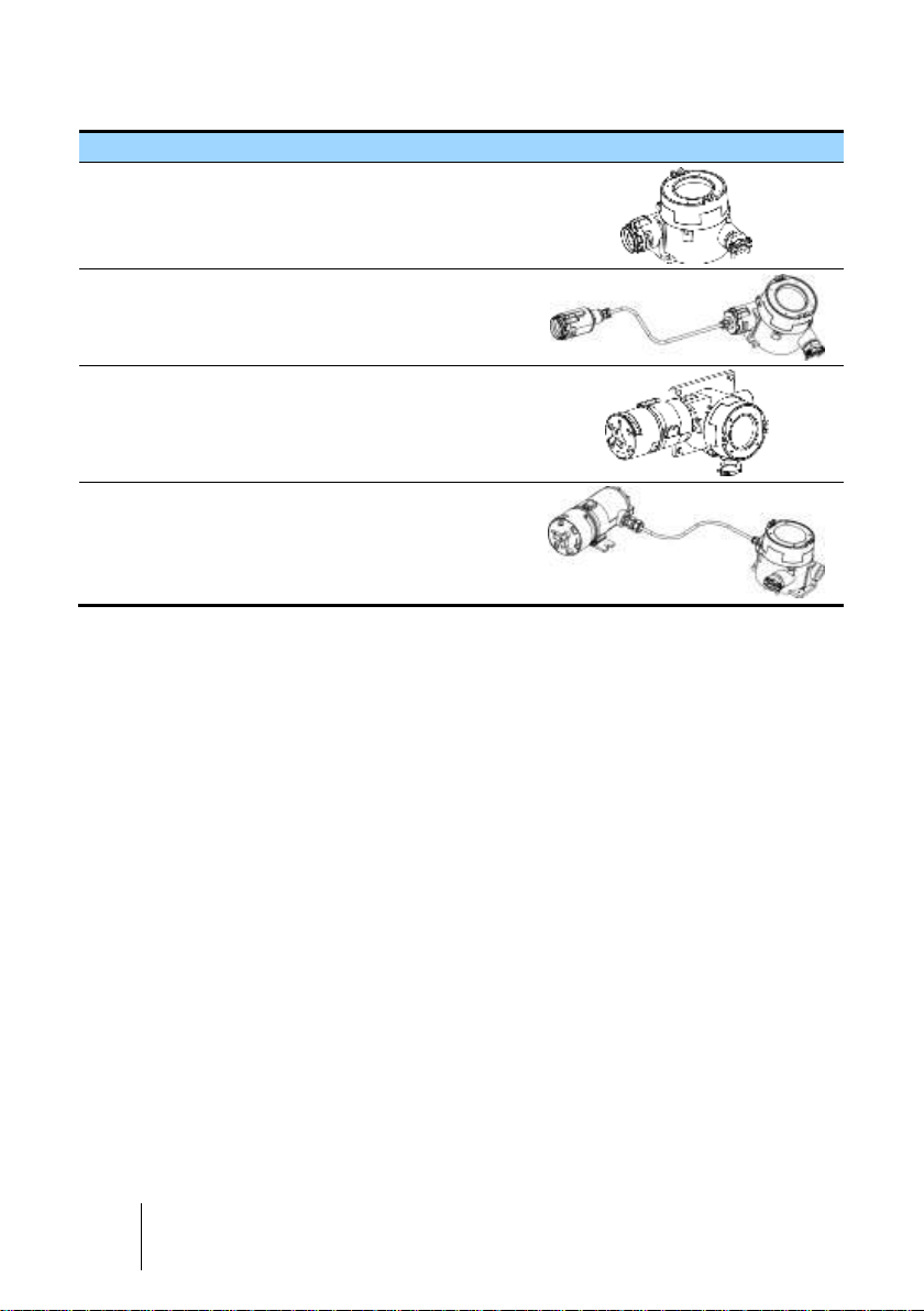
Available combinations are listed below.
Name
Description
Illustration
OLCT 60
Flameproof enclosure with onboard sensor (FLP or IS*).
044
OLCT 60D
Flameproof enclosure with remote
sensor 15m (FLP or IS*).
046
OLCT 60
/ OLCT IR
Flameproof enclosure with onboard infrared sensor type OLCT
IR.
048
OLCT 60D
/ OLCT IR
Flameproof enclosure with remote
infrared transmitter type OLCT IR.
050
(*) FLP stands for flameproof, IS stands for intrinsically safe. The IS version is distinguished - among other
features - by the color of its housing which is blue. FLP versions are unpainted stainless steel.
Operating principle
The sensor converts the target gas into current. The current value is amplified,
temperature compensated, linearized, and converted to a 4-20 mA signal proportional
to the gas concentration and then conveyed through a connecting cable to a
centralization system (gas controller or PLC).
Sensor type depends on the gas to be detected and the version of OLCT 60 as shown
in Table 1: Comparison of OLCT 60 detectors on page 9.
Page 11
1 - Overview
11
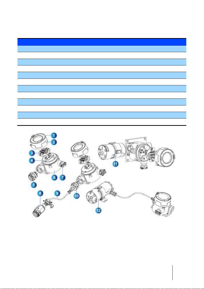
Composition of the Detector
OLCT 60 detectors contain the following parts:
Id.
Description
1.
Label
2.
Cover
3.
Display board
4.
Terminal board
5.
On-board sensor
6.
Enclosure
7.
M25 cable gland (until August 2014)
8.
Remote sensor
9.
Cable for remote sensor
10.
Adapter
11.
On-board OLCT IR infrared sensor
12.
Remote OLCT IR infrared transmitter
004
Figure 1: Main components of OLCT 60 detectors
Page 12

12
OLCT 60
User manual
External view
Overview
Id.
Description
1.
Digital display. See Figure 3 for more details.
2.
Ground terminal
3.
Cover fixation screw
4.
Cable gland (until August 2014)
5.
On-board sensor. See 9 for more details.
6.
Remote sensor. See 9 for more details.
7.
On-board OLCT IR infrared sensor head. See 9 for more details.
8.
Remote OLCT IR infrared transmitter. See 9 for more details.
012A
OLCT 60 OLCT 60D with remote sensor block
012B
OLCT 60/OLCT IR on-board OLCT 60/OLCT IR remote
012
Figure 2: OLCT 60 overview
Page 13
1 - Overview
13
Difference between FLP and IS sensors
Although they have different ATEX marking, intrinsically safe and flameproof sensors
are distinguished by the color of the sensor block as following:
Flameproof sensor: unpainted stainless steel enclosure equipped with a flame
arrestor,
Intrinsically safe sensor: blue painted stainless steel enclosure equipped a PTFE
membrane.
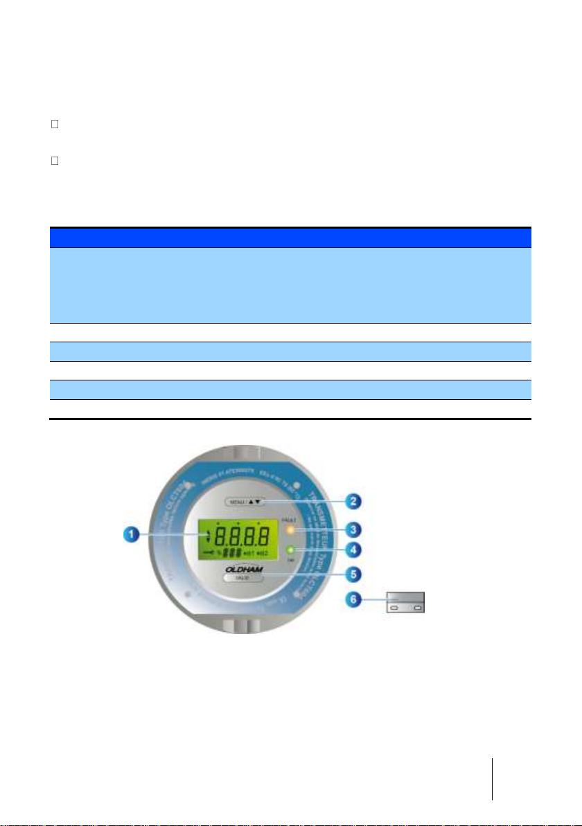
Display and LEDs
Id.
Description
1.
Digital display indicates:
- Gas concentration and gas type alternately with gas unit. If an error occurs, the
respective error code is displayed and Fault LED is lit on. Please revert to section
Readings on the display, page 16.
- Maintenance menus. Please revert to section Menus, page 16.
2.
Magnetic switch
3.
Fault LED (orange)
4.
Power LED (green)
5.
Magnetic switch
6.
Magnetic wand
018
Figure 3: General Status Screen
Page 14
14
OLCT 60
User manual
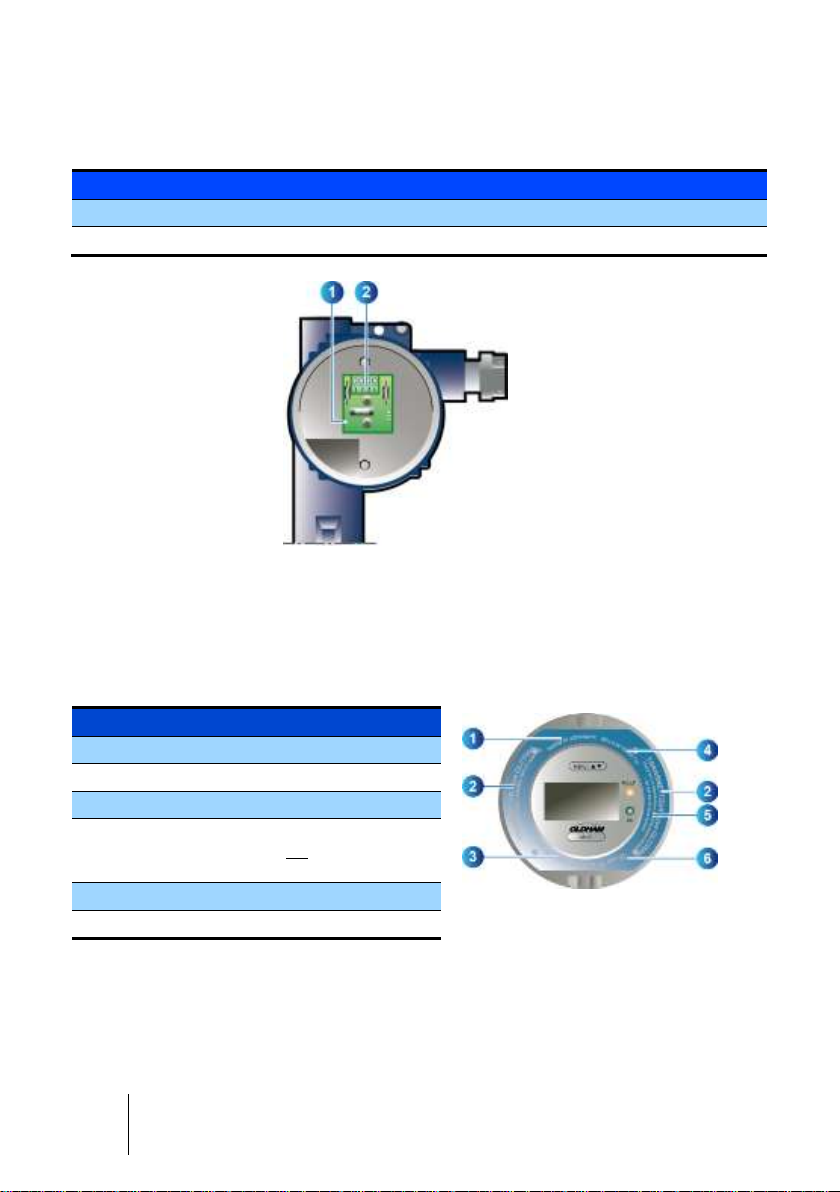
Internal view
Id.
Description
1.
Electronic circuit board
2.
Terminal block
006
Figure 4: Detector internal view (with display board removed)
Labels and pictograms
The detector has two identification labels, as shown below:
Certification label
Id.
Description
008
Figure 5: Certification label
1.
ATEX marking
2.
Type of product
3.
Manufacturer's name
4.
IECEx marking and ATEX certification
temperature range (is not the operating
temperature range)
5.
Warning
6.
CE and ATEX marking
Page 15
1 - Overview
15
P/N label
This label is located on the side of the enclosure and contains the following
information:
Id.
Description
010
Figure 6: Side label
1.
Part Number of the OLCT 60 without
sensor
2.
Disposal icon
3.
Serial Number
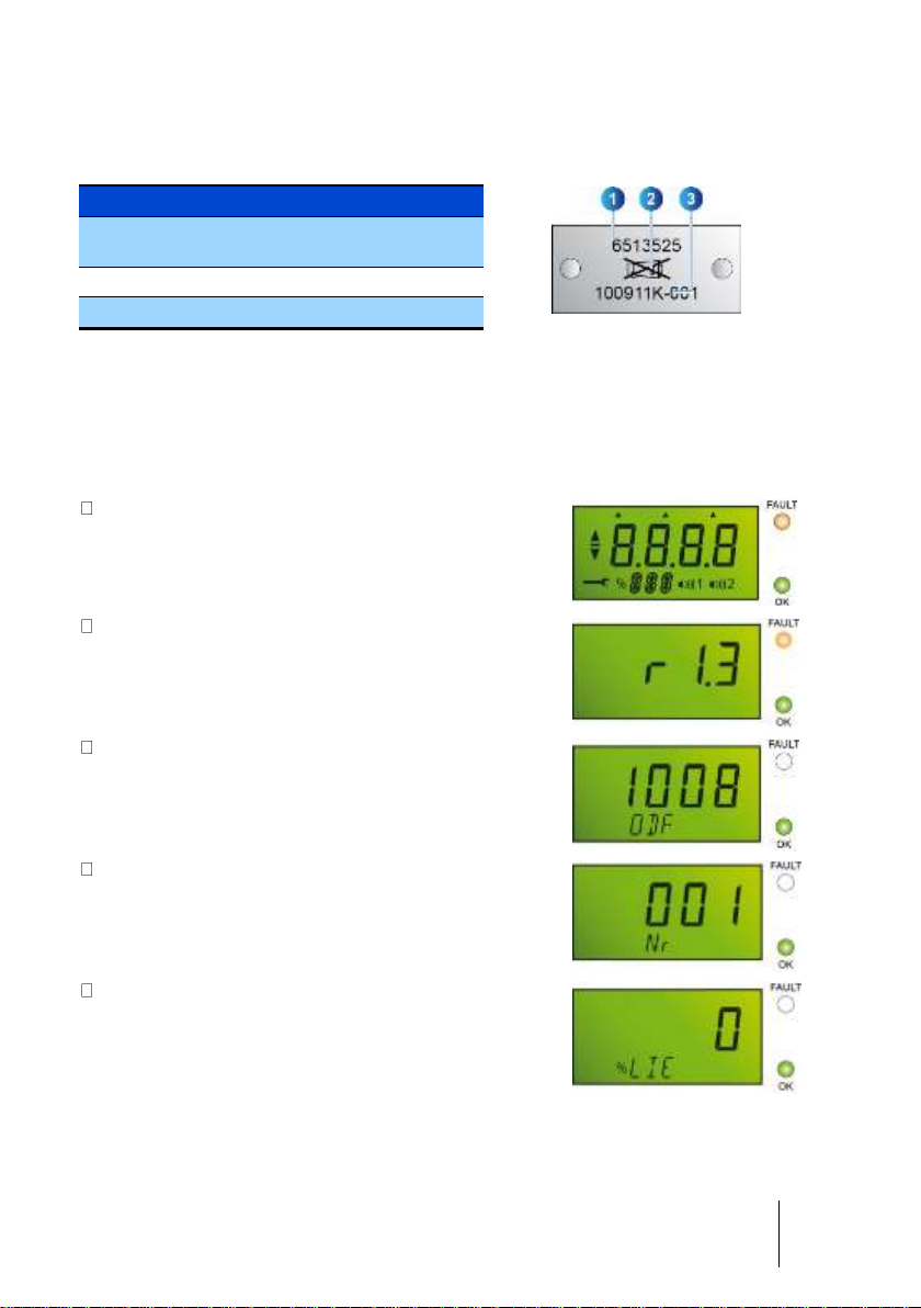
Visual indication
At startup
Display shows:
Initialization screen. All LCD segments and LEDs
turn on
L_00
Firmware version
L_02
Batch number
L_04
Serial Number
L_06
Gas concentration reading once initialization and
stabilization are completed
L_008
Figure 7: Warm-up screen
Page 16
16
OLCT 60
User manual
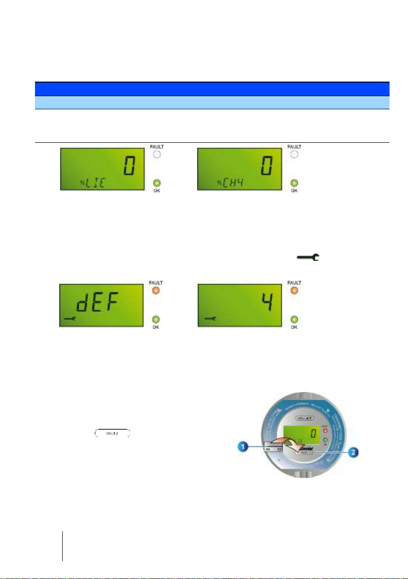
In normal operation
In normal operation, the display alternately shows the gas concentration, the type of
gas and the gas unit. The OK green indicator is lit on; the FAULT indicator is turned off.
Indicator
Lit
Off
OK
OLCT 60 is powered
OLCT 60 is not powered
FAULT
Detector in fault or in maintenance
mode
See Fault mode screen
Normal Operation
L_010A L_010B
Figure 8: OLCT 60 in normal operating mode
Fault mode screen
The display indicates DEF or the fault code (see page 73 for more warning code
information). Simultaneously, the FAULT indicator lights on and the icon is
displayed.
L_014A L_014B
Figure 9: OLCT 60 in fault mode
Maintenance Menus
Access
You can access the menus without opening the
enclosure thanks to a magnet (rep. 1) that must
be placed over (rep. 2).
034
Figure 10: place the magnet over
‘VALID’ to access the menus
Page 17
1 - Overview
17
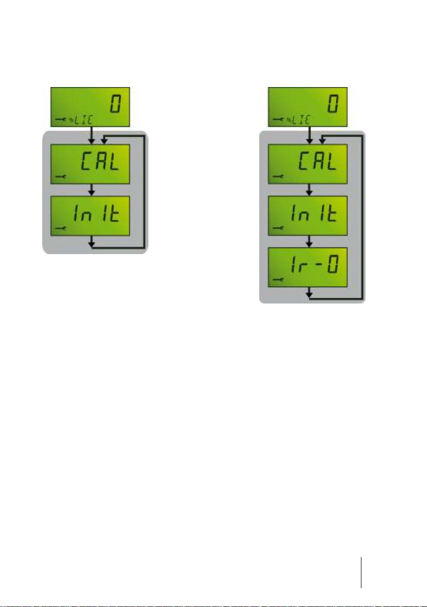
Gas calibration menu
The menu is different depending on whether the OLCT 60 is equipped with an OLCT
IR infrared sensor.
L_022_A
Normal operating mode
(page 31)
(page 42)
(page 39)
(page 47)
L_022B
Figure 11: Gas calibration menu (on the right: OLCT 60 equipped with an OLCT IR
infrared sensor)
• CAL: zero and span calibration. See page 42.
• Init: sensor replacement. See page 40.
• Ir-0: OLCT IR zeroing. See page 47.
Page 18

18
OLCT 60
User manual
Page 19

2 - Installation
19
Chapter 2 | Installation
Please read the guidelines on the installation, use and maintenance of
detectors for detection of flammable gases and oxygen (standard EN/IEC
60079-29-2) and toxic gases (standard EN 45544-4).
Regulations and conditions of use
The installation will be done according to current standards for installation in
explosive areas especially regulations IEC/EN 60079-14 and IEC/EN 60079-17
(current editions) or according to other national standards.
The equipment is authorized for use in Zones 1, 2, 21 and 22 and is certified for
ambient temperatures from -20 °C to + 60 °C. Note that this is not the operating
temperature which, by the way, is sensor dependent.
Regarding the OLCT 60D-id version, the remote sensor can be used in zones 0, 1,
2, 20, 21 and 22. The transmitter itself is for use in zones 1, 2, 21 and 22 only.
The detector must always be in contact with the ambient air. Thus:
- Do not cover the sensor,
- Do not paint the sensor,
- Avoid dust deposits.
Necessary equipment
• Complete detector assembly
• Cable
• Tools
• Fixing hardware
• Multimeter (intrinsically safe certified when needed)
Location of the detector
Depending on the density of the gas to be detected or the application, the detector
shall be positioned at ground level, or on the ceiling at the same height as the airflow,
or near air extraction ducts. Heavy gases may be detected at the ground level, while
light gases will be found at ceiling height. Gas densities are found on page 48.
Page 20
20
OLCT 60
User manual
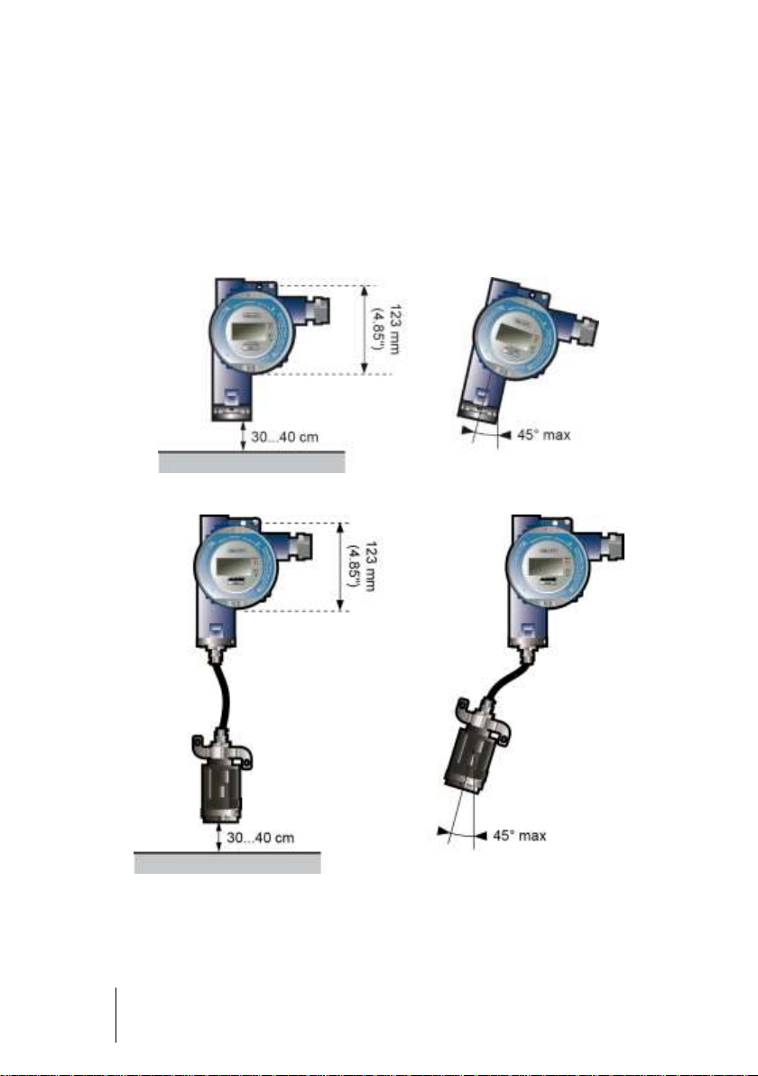
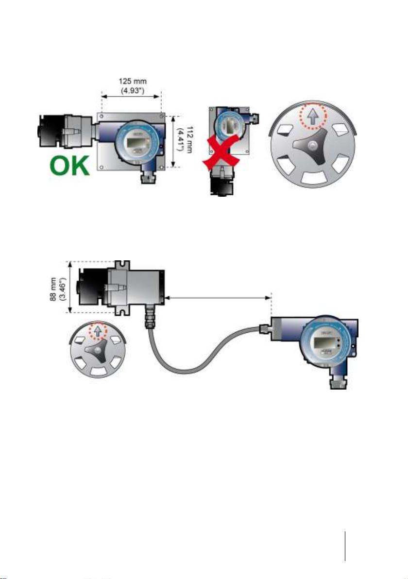
Detector positioning
All versions excluding OLCT IR
The OLCT 60 will be installed with the sensor pointing downwards. Any tilt of more
than 45° from the vertical will lead to an inaccurate measurement.
Fixing the enclosure will be performed by using 2 x M6 screws and the appropriate
plugs for the supporting material. A special holder is available for mounting the detector
on the ceiling (see chapter Accessories).
016
Figure 12: installation of an OLCT 60 with on-board sensor
036
Figure 13: installation of an OLCT 60D with remote sensor
OLCT 60 with local or remote OLCT IR
The infrared sensor shall be installed horizontally with the arrow on the splashguard
pointing upwards.
Page 21
2 - Installation
21
Fixing the detector will be performed by using 2 x M6 screws and the appropriate plugs
for the supporting material.
030
Figure 14: OLCT IR detector MUST be laid horizontally, arrow pointing upwards
056
Figure 15: OLCT IR detector must be laid horizontally, arrow pointing upwards
30m (100 ft) max.
Page 22

22
OLCT 60
User manual
Electrical Specifications
Type of sensor
Input Voltage
(Vdc)
Maximum
current
(mA)
Power
consumption
(W)
Catalytic
16 to 32
140
2.24
Infrared (XPIR)
16 to 32
120
1.92
Infrared (OLCT IR)
16 to 32
550
8.80
Electrochemical
16 to 32
80
1.28
Semiconductor
16 to 32
140
2.24
Connecting cable
The detector shall be connected to the controller with a 3-wire shielded cable. Core
size depends on the specific requirements of the installation, the distance and type of
detector (see table below).
022
Type of
detector
Type of sensor
Maximum length (km)
depending on the core size
Maximum load
resistance ()
0..5mm²
(AWG 20)
0.9 mm²
(AWG 18)
1.5 mm ²
(AWG 15)
Explosimeter
Catalytic
0.55
1.0
1.7
250
Explosimeter
Infrared (XPIR)
0.65
1.2
2.0
250
Explosimeter
Infrared (OLCT IR)
0.13
0.25
0.45
300
Toximeter
Electrochemical
1.0
1.8
3.0
250
Oxygen detector
Electrochemical
1.0
1.8
3.0
250
Freon
Semiconductor
0.55
1.0
1.7
250
Table 2: Maximum distance cable (with 24 Vcc at controller terminals)
The cable must be shielded to reduce the influence of electrical and radio-frequency
interference. A cable such as AFNOR M 87-202-01-IT-15-EG-FA (Nexans) may be
used. It shall be selected according to the type of detector and in accordance with the
table shown hereinabove. Here are some more examples of suitable cables:
Safe area: CNOMO FRN05 VC4V5-F
ATEX zone: GEVELYON (U 1000RHC1)
ATEX zone: GVCSTV RH (U 1000)
ATEX zone: xx-xx-09/15- EG-SF or EG-FA or EG-PF (U 300 compatible with M87202).
The maximum permissible length will depend on the cross-section of the cable
conductors (see table) and on the minimum admissible supply voltage at the detector
terminals.
Page 23
2 - Installation
23
Cable connection
Turn off the line
On the controller:
1. Inhibit any alarms to prevent false alarms during operation.
2. Switch off the power supply to the detector.
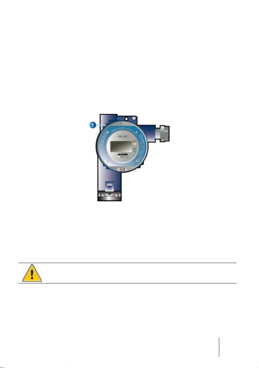
Opening of the detector
Loosen the 4mm hex screw (rep.1) locking the cover before removing the detector
cover.
032
Figure 16: Locking screw of the cover
Cable preparation
The cable will be supplied from the controller at the measurement point. The passage,
support, and protection of the cable shall be done according to best practice.
Cable entry
It is essential to follow the instructions given by the manufacturer of the cable gland
and to connect the shielding properly. Cable-gland or adaptor shall be M25 x 1.5
and flameproof certified.
Page 24

24
OLCT 60
User manual
060
Figure 17: non-armoured cable gland type
062
Figure 18: armoured cable gland type
Cable connection (OLCT 60)
Remove power before wiring the OLCT 60 to the controller. The site must be
equipotential.
Connect the cable to the detector first and then connect the controller. Once the wiring
is completed, connect the shield of the cable to the ground terminal of the controller.
026
Figure 19: wiring the OLCT 60 (d or id version)
+ 24 Vcc
0 V
Signal
Non-armoured
cable
Washer
Shielding
device
Seal
Detector
Shield
Cable clamp
Detector
Seal
Armour grounding
Armoured
cable
Seal
Page 25

2 - Installation
25
Cable connection (OLCT 60/OLCT IR remote)
Remove power before wiring the OLCT 60 to the controller. The site must be
equipotential.
First carry out the connection between the OLCT IR (rep. A) and the detector (rep. B)
as shown in Figure 20. The maximum distance is 30 meters (100 feet). The type of
cable to use is 01-IQ-09-EG-FA or EG-SF or similar; see page 22.
Then connect the OLCT 60 as described previously.
042
Figure 20: wiring the OLCT 60D/OLCT IR. Ensure the specificity of the numbering of the
connector marked «D» compared to the connector marked «E».
30m (100 ft) maximum
Page 26

26
OLCT 60
User manual
Detector grounding
Connect the enclosure ground points to earth according to the regulations with a 4mm²
(11 AWG) wire.
The OLCT 60 features an internal ground point as well. The internal grounding shall be
preferred as the primary equipment ground.
028
Figure 21: OLCT 60 grounding
Closing the cover
Before connecting the OLCT 60 to the controller, the cover shall be tightly closed.
Firmly tighten the locking screw as well (see Figure 16, page 23).
Page 27

2 - Installation
27
Scope of use
Gas sensors have limitations that must be observed (see Chapter 10 |
Special instructions for use in explosive environments and functional safety).
Presence of specific components
Vapors from components containing silicone or sulfur can affect the catalytic
sensors and thereby distort measurements. If sensors have been exposed to these
types of compounds, a bump test shall be performed.
High concentrations of organic solvents (e.g. alcohols, aromatic solvents, etc.) or
exposure to quantities of gas greater than the specified range of measurement can
damage the electrochemical sensors. Inspection or calibration is then
recommended.
In the presence of high concentrations of carbon dioxide (CO2 > 1% vol.), the
oxygen-measuring electrochemical sensors can slightly overestimate the
concentration of oxygen (0.1 to 0.5% volume O2 overestimate).
Operation under low oxygen levels
If an electrochemical sensor is used in an atmosphere comprising less than 1%
oxygen for over one hour, the measurement may be an underestimate.
If a catalytic sensor is used in an atmosphere comprising less than 10% oxygen,
the measurement may be an underestimate.
If a semiconductor detector sensor is used in an atmosphere comprising less than
18% oxygen, the measurement may be an underestimate.
Transfer curve
The curve shown gives the transmitter
output current as a function of the gas
concentration. If you connect the
transmitter to a different unit than the
one provided by Oldham, you should
be certain that the transfer curve is
fully compatible with the input
characteristics of your device to ensure
proper interpretation of the information
provided by the transmitter. Similarly,
the unit should provide sufficient
voltage to compensate for any voltage
drop in the cable.
014
Figure 22: OLCT 60 transfer curve
Output signal (mA)
% of the
measuring range
Default
Default
Page 28

28
OLCT 60
User manual
Page 29

3 – Commissioning
29
Chapter 3 | Commissioning and
operating modes
The tasks described in this chapter should only be performed by
authorized and trained personnel as they are likely to jeopardize the
reliability of detection.
This chapter describes:
how to check the zero
how to check the sensitivity
the various operating modes
Purpose of control
Upon delivery, each detector has been tested and calibrated. There is normally no
need for a new calibration.
However, for safety, it is advisable to check the zero and the sensitivity as shown
below.
The detector cover shall remain completely closed since the adjustments
are carried out through the window.
For flammable gas detector, we always recommend to calibrate the sensor
with the targeted gas. When the user wishes to calibrate the detector with a
different gas, refer to the table on page 48 for the use of recommended gas
and corresponding coefficient.
Necessary equipment
• Zero grade air cylinder
• Appropriate span gas cylinder (gas concentration should be between 30 and
70% of the measurement range)
• Calibration cup (see Chapter Accessories)
Page 30

30
OLCT 60
User manual
Commissioning
Prior checks
Check the following points:
Wiring completed
Detector grounded
Shielding grounded at controller side
Integrity of the mechanical mounting (fixings, cable gland, and cover) ensured
Powering up detector
1. Inhibit any alarms to avoid false alarms during operation
2. Apply power to the OLCT 60
Stabilization time
Before initial calibration allow the detector to stabilize after applying power. Any
adjustment before the time indicated will result in an incorrect measurement, which
may in turn compromise the safety. The total waiting time is summarized below:
Catalytic bead sensor: 2 hours
Oxygen sensor: 1 hour (2 year sensor) to 1.5 hour (5 year sensor)
Electrochemical sensor: 1 hour, excluding:
- NO (Nitrogen Monoxide): 12 hours
- HCl (Hydrogen Chloride): 24 hours
- ETO (Ethylene Oxide): 36 hours
Semiconductor sensor: 4 hours
Infrared sensors (XPIR and OLCT IR): 2 hours
Page 31

3 – Commissioning
31
Display of the gas measurement
Normal operating mode
Alternately, the display shows the measured
concentration and the type of gas.
The OK green indicator is lit; the FAULT indicator is
off.
L_00
Figure 23: Normal operating
mode
Fault mode
In fault condition, the display indicates «dEF»
followed by the fault code.
In the event of an internal electronic error, the
display indicates «E» followed by the error code.
In both cases, the FAULT indicator is lit. Proceed
with the corrective action in compliance with page
37. See page 73 for more warning code
information.
L_00
Figure 24: Fault mode
Over-Range condition
(catalytic version only)
For safety reasons, when measuring a
concentration of a flammable gas above 100% LEL,
the display indicates «SUP» and the FAULT
indicator is lit. Meanwhile the analog output signal is
set at 23.2 mA.
To exit this mode, swipe the magnet over
once you have checked the absence of any
explosive atmosphere with a portable combustible
gas monitor for example.
L_00
Figure 25: Over-Range
indication
Page 32

32
OLCT 60
User manual
Checking Zero
Proceed as follows:
024
Figure 26: Checking Zero
1. Inhibit any alarms on the controller.
2. Place the calibration cup over the sensor (Figure 26, rep. B).
3. Connect the calibration cup to the zero gas cylinder (rep. E) by using a tubing in
PTFE (Pos. C).
4. Apply the gas (flow regulator set to 0.5-1.0 liter per minute (LPM) or 1.0-2.0 LPM for
OLCT IR versions) (rep. D).
5. Once the measure is stabilized (approx. 2 minutes), read the value on the display
(rep. A).
6. If the expected value does not comply, proceed with the calibration (paragraph
Zeroing and sensitivity adjustment, on page 42).
7. Continue with Checking gas sensitivity on the next page.
Page 33

3 – Commissioning
33
Checking gas sensitivity
For safety reasons, this procedure must be carried out after the control of the zero
(page 31). Proceed as follows:
038
Figure 27: Checking gas sensitivity
1. Once the detector is zeroed, connect the calibration cup to the calibration gas
cylinder (Pos. E) by using a tubing in PTFE (Pos. C) to prevent the adsorption of
reactive gases (i.e.: HCl, SO2, Cl2, etc.) at the surface of the tube.
2. Open the valve on the gas cylinder (flow rate 0.5 to 1 LPM or 1 to 2 LPM in the case
of OLCT IR versions) (rep. D).
3. Once the measurement is stabilized (approx. 2 minutes), read the value on the
display (rep. A).
4. If the expected value does not comply, proceed with the calibration (paragraph
Zeroing and sensitivity adjustment, on page 42).
5. Close the valve (rep. D) of the gas cylinder and remove the calibration cup (rep. B).
Wait for the measurement to return to zero and reset the alarms on the controller.
The control of zero and gas sensitivity is now completed.
Page 34

34
OLCT 60
User manual
Page 35

4 – Preventive maintenance
35
Chapter 4 | Preventive
maintenance
Periodic checks enable the equipment and installation to remain in conformity and
ensure reliable detection. This chapter describes what preventative action should be
taken and at what intervals. Inspection and maintenance are carried out in
accordance with EN/IEC 60079-17 standard in force or with other national standards.
Maintenance schedule
Gas detectors are safety devices. OLDHAM recommends the regular testing of fixed
gas detection installations. This type of test consists of injecting the calibration gas into
the detector at a sufficient concentration to activate the pre-set alarms. It is to be
understood that this test is in no way a replacement for a detector calibration.
The frequency of gas tests depends on the industrial application where the detector is
in use. Frequent inspections should be made in the months following the
commissioning of the installation, and should then become more widely spaced
provided that no significant deviation is observed. If a detector should fail to react in
contact with the gas, calibration is essential. The frequency of calibrations shall be
appropriate according to the results of the tests (humidity, temperature, dust, etc.);
however, it must not exceed one year.
The general manager should put safety procedures in place on-site. OLDHAM cannot
be held responsible for their enforcement.
When used in a SIL 1 system, according to European standard EN
50402, Requirements relating to the safety operation of fixed gas
detection systems, the maintenance interval for combustible gas
detectors shall not exceed 6 months.
For SIL 2 systems, the maintenance interval shall not exceed 3
months.
Page 36

36
OLCT 60
User manual
Actions
OLCT 60
Periodic maintenance comprises the following actions:
Removal of dust from the sensor and its optional protective cover with a dry cloth
only. No water or solvents should be used. Severely dusty sensors should be
replaced immediately.
For use in dusty explosive atmospheres, the user should undertake full and regular
cleaning to avoid the build-up of dust. The maximum permissible thickness of a
dust layer must be less than 5 mm.
Replacement of screws: if any screws on the flameproof part need to be replaced,
screws of equal quality or better than A4.70 should be used.
Zero inspection with zero grade air; see page 31. In case of variance, comply with
the actions described in this paragraph.
Gas sensitivity check; see page 32. In case of variance, comply with the actions
described in this paragraph.
OLCT 60/ OLCT IR
Refer to the specific OLCT IR manual.
Page 37

5 - Maintenance
37
Chapter 5 | Maintenance
Maintenance primarily comprises changing any sensors that no longer meet their
initial metrological characteristics.
Since they are liable to affect detection reliability, the tasks described
in this chapter are reserved for authorized trained personnel only.
Inspection and maintenance shall be carried out in accordance with
EN/IEC 60079-17 standards in force or with other national standards.
Possible errors
The table below summarizes the various possible detector errors.
Observed default
Possible cause
Action
(page )
current output is at
0 mA
Connector cable
Power supply
Check cable
Check voltage at detector
terminal
52
-
Electronic card
Change board
-
0 mA < current
output < 1mA
Sensor
Line resistance too high
Power supply
Change sensor
Check cable
Check voltage at detector
terminal
38
-
-
Improper calibration gas
Check the content of the
calibration gas
-
Zero setting not
possible
Sensor
Electronic card
Change sensor
Change board
38
Sensitivity
adjustment not
possible
Sensor
Electronic card
Change sensor
Change board
38
«SUP» display
Over-Range condition
Valid with the magnet
31
Check the span
44
Page 38

38
OLCT 60
User manual
Replacing sensor block
(Explo, O2, Tox, XPIR)
This paragraph is not applied to OLCT IR. Refer to the two paragraphs
Replacing the OLCT IR on the next page.
The sensor block or detection module encloses the sensitive element and the
corresponding electronics. A sensor block can only be associated with a defined
detector; so an oxygen detection module will not be installed in the place of a LEL
detection module.
Frequency of replacement
The sensor block needs to be replaced every time when zeroing, performing gas
calibration or preventive maintenance are no longer possible.
Exchanging of the sensor
Step
Action
1.
Prepare the following elements:
New sensor block
4 mm Allen wrench
Calibration set (gas cylinder, calibration cup, etc.).
2.
Inhibit the alarms on the controller.
3.
Turn the OLCT 60 off.
4.
Loosen the locking screw in the sensor head and rotate the sensor head 30
degrees counterclockwise.
5.
Unplug the connector and remove the defective sensor head.
6.
Replace the worn out detector head with an identical new one.
7.
Reassemble in reverse order and tighten the locking screw.
8.
Power the OLCT 60.
9.
Install the OLCT 60 as explained in detail in the Initialization of the sensor
block paragraph on page 39.
Page 39

5 - Maintenance
39
Replacing the OLCT IR – integrated version
Contact the manufacturer or distributor.
Replacing the OLCT IR – remote version
Exchanging the detector
Step
Action
1.
Prepare the following elements:
New OLCT IR detector
4 mm Allen wrench
Calibration set (gas cylinder, calibration cup, etc.).
2.
Inhibit the alarms on the controller.
3.
Turn the OLCT 60 off.
4.
Open the defective OLCT IR and disconnect it.
5.
Dismount the defective OLCT IR and put the new one in.
6.
Carry out the connections. Refer to the Connection of the cable (OLCT
60/OLCT IR remote version) paragraph on page 24.
7.
Reassemble in reverse.
8.
Power the OLCT 60.
9.
Install the OLCT 60 as explained in detail in the Initialization of the
sensor block paragraph on page 39.
Page 40

40
OLCT 60
User manual
Initialization of the sensor block
Selection of the initializing menu (
Init
)
Step
Action
Illustration
1a.
After the startup phase, the screen will
show the gas measurement (it may be
wrong at this point). Place the magnet over
for 3 seconds.
L_020A
1b.
Until the icon is displayed...
_L020B
...present the magnet 3 consecutive times
on the in the 3 seconds.
L_020B
1c.
The calibration menu (CAL) is displayed.
L_020c
1d.
Place the magnet over .
1e.
The initialization menu (Init) is displayed.
L_Init
Initialization of the sensor block
This procedure resets the electrical parameters of the sensor.
Step
Action
Illustration
2a.
The Init screen is displayed, place the
magnet over .
L_020B
2b.
The display indicates «CnF» (Confirmation).
L_044
2c.
Place the magnet over .
Page 41

5 - Maintenance
41
2d.
The display indicates «nOn» (No).
L_048
2e.
Place the magnet over to change
No to Yes.
L_046
2f.
Place the magnet over to validate
the choice. The procedure is then ended
and the detector automatically resets.
2g.
Wait 4 seconds during the display of the
startup page.
L_00
2h.
The version number of the software is
displayed.
L_02
2i.
The manufacturing date code is displayed.
L_04
2j.
The serial number is displayed.
L_06
2k.
Countdown starts before return in normal
mode.
L_059
2l.
When the countdown is ended, the display
shows the gas measurement. The OLCT 60
is in normal mode.
L_020A
2m.
Subsequently check the gas operation as
explained on pages 31 and 32.
Page 42

42
OLCT 60
User manual
Zeroing and sensitivity adjustment (calibration)
This paragraph will be followed to the extent that the zero control (page 31)
and/or the sensitivity (page 32) show a variance from the expected values.
For safety reasons, it is important to proceed with the full calibration (zero
and span settings).
In the event of a voluntary or an automatic abandon of the procedure, the
previous values will be maintained.
OLCT 60 leaves the maintenance mode and returns to normal operation
after 10 minutes of inactivity on the
or .
The detector cover shall remain completely closed since the adjustments
are carried out through the window.
For flammable gas detector, we always recommend to calibrate the sensor
with the targeted gas. When the user wishes to calibrate the detector with a
different gas, refer to the table on page 48 for the use of recommended gas
and corresponding coefficient.
FOR OLCT IR infrared versions
It is imperative to zero the optics before proceeding as indicated in the
Optical zeroing on page 47
Passage in calibration mode
Step
Action
Illustration
1a.
Place the magnet over
for 3
seconds.
L_020A
1b.
Until the icon is displayed...
_L020B
...present the magnet 3 consecutive times
on the in the 3 seconds.
L_020B
1c.
The calibration menu (CAL) is displayed.
L_020c
Page 43

5 - Maintenance
43
Zeroing
Step
Action
Illustration
2a.
The calibration menu (CAL) is displayed.
L_020C
Position the magnet over .
2b.
The display now shows “-0-” indicating the
beginning of the zero-setting phase.
L_024
2c.
Position the magnet over .
2d.
The display indicates the current value.
L_026
2e.
Place the calibration cup and inject zero
grade air at 0.5 to 1 LPM (1 to 2 LPM for
OLCT IR versions).
Wait approximately 2 minutes for the
stabilization of the measure.
The zero of a CO2 sensor
block must be tested with a
zero grade air cylinder or with
nitrogen. Never consider
ambient air as a zero value.
2f.
The display eventually indicates a value that
is different than zero.
Place the magnet over to confirm
the zero adjustment.
L_028
2g.
«GE» (Span Gas) is displayed to indicate
that the system has switched over to the
sensitivity adjustment phase.
L_030
Page 44

44
OLCT 60
User manual
Adjustment of gas sensitivity
Accessing the sensitivity adjustment menu
Step
Action
Illustration
3a
«GE» (Span Gas) is displayed to indicate
that the system has switched over to the
sensitivity adjustment phase.
L_030
Setting the Span Gas concentration
Step
Action
Illustration
4a
Place the magnet over .
4b.
The displayed value corresponds to the
span gas value by default (50 in the
example).
The hundreds digit flashes.
L_032
4c.
Adjusting the hundreds
Adjust the value of the hundreds by placing
the magnet over . Each time you
place the magnet over, you increase the
digit value.
L_032
4d.
Confirm the value by placing the magnet
over .
4e.
Adjusting the tens
The tens digit flashes. Repeat the same
procedure as for the hundreds.
L_034
4f.
Adjusting the units
The unit digit flashes. Repeat the same
procedure as for the hundreds.
L_036
4g
Validate the digit of the units by placing the
magnet over .
4h.
End of the procedure.
Page 45

5 - Maintenance
45
Injecting calibration gas
Step
Action
Illustration
5a.
The display indicates «S» (Sensitivity).
L_038
5b.
Place the calibration cup on the sensor and
inject the span gas at flow rate between 0.5
and 1 LPM (1 to 2 LPM for OLCT IR versions).
5c.
Position the magnet over .
5d.
The displayed value keeps changing until it
stabilizes. Wait approximately 2 minutes for
the stabilization of the measure.
L_040
5e.
As soon as the instrument stabilizes at a
value, place the magnet over to
exit the sensitivity adjustment function.
Continue to step 6a.
L_042
Validating your calibration
Step
Action
Illustration
6a.
The display indicates «CnF» (Confirmation).
L_044
6b.
Position the magnet on .
6c.
The display indicates «nOn» (No).
L_048
6d.
To validate and confirm your calibration
values, set the magnet on to
change No into Yes and then on to
confirm. Continue as under paragraph End of
zero-point adjustment and calibration.
L_046
6e
Otherwise place the magnet on .
When you do so, the detector will return to
normal mode after a one-minute countdown
and without applying any of the previous
adjustments.
L_048
Page 46

46
OLCT 60
User manual
End of the zero-setting and calibration procedure
Step
Action
Illustration
7a
The OLCT 60 starts a countdown before
returning in normal operation mode.
Please note: The countdown time is sensor
dependent.
L_059
7b.
Close the cock of the calibration gas cylinder
and remove the calibration cup.
7c.
As soon as the countdown is over, the
ambient gas concentration must be shown
on the display. The detector is now in
normal operation mode.
Restore the alarms on the controller.
L_052
7d.
If the display shows «dEF» (Fault) followed
by the fault number, it means that the
detector is not operational.
Check the fault code number (page 73) and
implement the recommended remedies. See
page 37.
L_054
Page 47

5 - Maintenance
47
Adjusting the optical zero (Ir-0)
(for OLCT IR versions)
This menu strictly applies for OLCT IR versions prior to set the zero or the
sensitivity or after cleaning optical parts (see page 42).
Cleaning the optical parts is described in the manual of the
OLCT IR.
Selecting the menu
Step
Action
Illustration
1a.
Place the magnet over
for 3
seconds.
L_020A
1b.
Until the icon is displayed...
_L020B
...present the magnet 3 consecutive times
on the in the 3 seconds.
L_020B
1c.
The calibration menu (CAL) is displayed.
L_020c
1d.
Place the magnet twice on .
1e.
The optical zero setting menu (Ir-0) is
displayed.
L_IR0
1f.
Inject zero grade air at 1 to 2 LPM for 2
minutes and then place the magnet over
.
_L020B
1g.
The display indicates «CnF» (Confirmation).
L_044
1h.
Place the magnet over .
Page 48

48
OLCT 60
User manual
1i.
The display indicates «nOn» (No).
L_048
1j.
Place the magnet over to change
No to Yes and adjust the optical zero.
Place the magnet over to validate
the choice.
Please continue as in paragraph Changing
over to calibration mode, page 42.
L_046
1k.
Place the magnet over to confirm
No and exit the optical zero setting menu.
L_048
Page 49

5 - Maintenance
49
Applicable coefficients for explosive gas
calibration
Catalytic sensor type VQ1
The applicable coefficients are shown in the following table.
Gas
Chemical
Formula
LEL
(%)
LSE
(%)
Flash
point (°C)
Vapor
density
Coefficient
-
Calibration gas
CH4 (methane)
Coefficient
Calibration gas
H2 (Hydrogen)
Coefficient
- Calibration gas
C4H10 (Butane)
Coefficient
- Calibration gas
C5H12 (Pentane)
Ethyl acetate
C4H8O2
2,10
11,50
-4
3,0
1,65
1,35
0,90
0,80
Acetone
C3H6O
2,15
13,00
-18
2,1
1,65
1,35
0,90
0,80
Acetylene
C2H2
2,30
100
-18
0,9
2,35
1,90
1,25
1,15
Acrylic acid
C3H4O2
2,40
8,00
54
2,5
5,00
4,00
2,65
2,40
Butyl acrylate
C7H12O2
1,20
8,00
37
4,4
3,50
2,80
1,85
1,70
Ethyl acrylate
C5H8O2
1,70
13,00
-2
3,5
3,05
2,45
1,65
1,50
Acrylonitrile
C3H3N
2,80
28,00
-1
1,8
1,45
1,20
0,80
0,70
Ammoniac
NH3
15,00
30,20
< -100
0,6
0,90
0,75
0,50
0,45
Benzene
C6H6
1,20
8,00
-11
2,7
4,00
3,20
2,15
1,90
1.3-Butadiene
C4H6
1,40
16,30
-85
1,9
2,55
2,05
1,35
1,25
Butane
C4H10
1,50
8,50
-60
2,0
1,90
1,55
1,00
0,90
Butanol (Butyl
Alcool)
C4H10O
1,4
11,3
29
2,6
1,95
1,60
1,05
0,95
2 - Butanone
(MEK)
C4H8O
1,80
11,50
-4
2,5
3,90
3,15
2,10
1,90
Cyclohexane
C6H12
1,20
8,30
-17
2,9
2,00
1,60
1,10
1,00
Dimethylether
C2H6O
3,00
27,00
-41
1,6
1,80
1,45
0,95
0,90
Dodecane
C12H26
0,60
~6,0
74
5,9
4,00
3,20
2,15
1,90
Ethane
C2H6
3,00
15,50
135
1,0
1,50
1,20
0,80
0,75
Ethanol
C2H6O
3,30
19,00
13
1,6
2,15
1,75
1,15
1,05
Ether
(Diethylether)
(C2H5)2O
1,70
36,00
-45
2,6
1,90
1,55
1,00
0,90
Ethylene
C2H4
2,70
34,00
- 135
1,0
1,65
1,35
0,90
0,80
LPG
Prop+But
1,65
~9,0
< -50
1,9
1,90
1,55
1,00
0,90
Diesel
Melange
0,60
~6,0
55
> 4
3,20
2,60
1,70
1,55
Natural Gas
CH4
5,00
15,00
-188
0,6
1,05
Heptane
C7H16
1,10
6,70
-4
3,5
2,20
1,80
1,20
1,05
Hexane
C6H14
1,20
7,40
-23
3,0
2,10
1,70
1,15
1,00
Hydrogen
H2
4,00
75,60 - 0,069 1,00
Isobutane
C4H10
1,50
8,40
-83
2,0
1,50
1,20
0,80
0,75
Isobutene
C4H8
1,60
10,00
<-10
1,9
2,20
1,80
1,20
1,05
Isopropanol
C3H8O
2,15
13,50
11,7
2,1
1,60
1,30
0,85
0,80
Page 50

50
OLCT 60
User manual
Gas
Chemical
Formula
LEL
(%)
LSE
(%)
Flash
point (°C)
Vapor
density
Coefficient
Calibration gas
CH4 (methane)
Coefficient
Calibration gas
H2 (Hydrogen)
Coefficient
- Calibration gas
C4H10 (Butane)
Coefficient
- Calibration gas
C5H12 (Pentane)
Kerosene
(JP4)
C10 - C16
0,70
5,00
> 50
> 4
5,00
4,00
2,65
2,40
Methyl
Methacrylate
C5H8O2
2,10
12,50 2 3,5
2,25
1,80
1,20
1,10
Methane
CH4
5,00
15,00
-188
0,55
1,00
Methanol
CH3OH
5,50
44,00
11
1,1
1,40
1,15
0,75
0,70
Naphta
melange
(Mixture)
0,90
5,90
> 44
> 4
3,50
2,80
1,85
1,70
Nonane
C9H20
0,70
5,60
31
4,4
4,40
3,55
2,35
2,10
Octane
C8H18
1,00
6,00
12
3,9
2,70
2,20
1,45
1,30
Ethylene
Oxyde
C2H4O
2,60
100
-20
1,5
2,10
1,70
1,15
1,00
Propylene
oxide
C3H6O
1,90
37,00
70
2,0
2,35
1,90
1,25
1,15
Pentane
C5H12
1,40
8,00
-49
2,5 1,00
Propane
C3H8
2,00
9,5
-104
1,6
1,55
1,25
0,85
0,75
Propylene
C3H6
2,00
11,70
-107,8
1,5
1,65
1,35
0,90
0,80
Styrene
C8H8
1,1
8,00
31
3,6
6,30
5,05
3,35
3,00
Gasoline lead
free
/
1,10
~6,0
21
3 à 4
1,80
1,45
0,95
0,90
Toluene
C7H8
1,20 7 5
3,1
4,00
3,20
2,15
1,90
Turpentine Oil
-
0,8
6,0
35
4,7
3,50
2,80
1,85
1,70
Triethyl amine
C6H15N
1,20 8 -15
3,5
2,05
1,65
1,10
1,00
White Spirit
melange
(Mixture)
1,10
6,50
>30
> 4
3,50
2,80
1,85
1,70
Xylene
C8H10
1,00
7,60
25
3,7
4,00
3,20
2,15
1,90
: recommended gas for detector calibration
Table 3: Coefficients for the calibration of catalytic detectors equipped with a standard
sensor VQ1
Page 51

5 - Maintenance
51
4F poison resistant catalytic bead sensor
The applicable coefficients are:
Gas
Chemical
Formula
LEL %
LSE % Vapor
density
CH4
Coef
C5H
12
Coef
H
2
Coef
Acetone
C3H6O
2,15
13,0
2,1
1,8
0,9
1,1
Acetylene
C2H2
2,3
100
0,9
1,4
0,7
Ammoniac
NH3
15,0
30,2
0,6
1,0
0,5
Benzene
C6H6
1,2
8,0
2,7
2,10
1,05
n-Butane
C4H10
1,5
8,5
2,0
1,8
0,9 Ethane
C2H6
3,0
15,5
1,0
1,4
0,7
Ethanol
C2H6O
3,3
19,0
1,6
1,6
0,8
Ethylene
C2H4
2,7
34,0
1,0
1,4
0,7
n-Hexane
C6H14
1,2
7,4
3,0
2,85
1,4
HFO-1234yf
6.2
12.3 1.25
0.55
Hydrogen
H2
4,0
75,6
0,07
1,0
Isopropanol
C3H8O
2,15
13,5
2,1
1,8
0,9 JP-4
3,0
1,5
JP-5
3,1
1,55
JP-8
3,2
1,6
Methane
CH4
5,0
15,0
0,55
1,0
Methanol
CH3OH
5,5
44,0
1,1
1,35
0,65
n-Pentane
C5H12
1,4
8,0
2,5
2,0
1,0
Propane
C3H8
2,0
9,5
1,6
1,6
0,8 Styrene
C8H8
1,1
8,0
3,6
2,4
1,2
Toluene
C7H8
1,2
7,0
3,1
2,5
1,25
Xylene
C8H10
1,0
7,6
3,7
2,4
1,2
: recommended gas for detector calibration
Table 4: Coefficients for the calibration of detectors equipped with a 4F poison resistant
catalytic bead
Example: (Catalytic sensor type VQ1, Table 3)
Calibration of an «acetone» detector with span gas at 1% butane concentration.
Value to be entered for the span gas concentration («GE», step 4b, page 44):
1% (injected butane) x 100 x 0.90 (butane/acetone coefficient) = 60 % LEL
1.5 % (LEL butane)
Please note:
LEL values vary according to the source
Coefficients are accurate to ± 15 %.
For other gases/vapors consult our technical service.
Page 52

52
OLCT 60
User manual
Checking the line current
040
Figure 28: Checking the current generator of the detector
Proceed as follows:
1. Check the detector for proper power supply (+24V between terminal 2 and 3).
2. Switch the multimeter over to current measurement (mA range).
3. Make sure to inhibit the controller to avoid any false alarm. Disconnect the signal
wire (terminal 1, Pos. B). Connect the «COM» terminal of the multimeter (Pos. D) to
terminal 2 (0 V) of the detector (Pos. A).
4. Connect the «mA» terminal of the multimeter (Pos. D) to terminal 1 (signal) of the
detector (Pos. A).
5. The current must be 4 mA (Pos. C) when zero grade air is applied on the sensor
and 20 mA when applying span gas of concentration equal to the full scale.
6. Once testing is completed, connect back the signal wire to terminal 1 (Pos. B).
+ 24 VDC
0 V
Signal
Page 53

6 - Accessories
53
Chapter 6 | Accessories
The following accessories do not apply for OLCT 60/OLCT IR. For the latter please
revert to the OLCT IR manual.
Accessories
Utilization
Illustration
Illustration
Tool Kit
Opening of the OLCT 60 and
sensor replacement
6147870
OLCT
60/OLCT IR
calibration set
Please read OLCT IR manual. The
calibration cup is different and the
flow rate must be between 1 and 2
LPM.
6313863
Calibration
cup
Shall be used for sensor
calibration.
204
6331141
Plastic
material. Risk of
electrostatic
charges. Wipe
with a damp
cloth
By-pass
adaptor
Allows bypass measuring.
Effects on measurement: no effect
if calibration is done in the same
conditions (pipe, flow).
Effects on response time: none.
200
6327910
Plastic
material. Risk of
electrostatic
charges. Wipe
with a damp
cloth
Splash-guard
Protects the sensor against
splashing liquids.
Effects on measurement: none.
Effects on response time: the
response time at natural diffusion
may increase for certain gases.
Please consult us.
202
6329004
Plastic
material. Risk of
electrostatic
charges. Wipe
with a damp
cloth
Page 54

54
OLCT 60
User manual
Accessories
Utilization
Illustration
Illustration
Stainless steel
Splash-guard
kit
Protects the detector against
splashes
Effect on measurement: no effect.
Effect on response time: response
time for natural diffusion can
increase for certain gases. Contact
us for details.
6129010
Remote
calibration cup
Allows gas detection and the use
of a tubing for calibration gas
injection. For combustible gases
only. Flow rate 1 LPM minimum.
Effects on the measurement:
none.
Effects on response time:
negligible.
214
6327911
Plastic
material. Risk of
electrostatic
charges. Wipe
with a damp
cloth
PTFE
protection filter
Protects the sensor against
splashing liquids and dust
contamination.
Effects on the measurement: no
effect, but cannot be used to
detect O3, HCL, HF, CL2.
Effects on response time:
increased response time
(please consult us for high-density
gas > 3 and low concentrations <
10 ppm).
216
6335975
Plastic
material. Risk of
electrostatic
charges. Wipe
with a damp
cloth
Ceiling gas
collector
Allows the sensor to detect gas
more quickly.
Effects on the measurement:
none.
Effects on response time: may
increase by 10%
6323620
Magnet
Used for menu selection through
the detector glass window.
218
6155651
Cable entry
adaptor
M25 / M20 adaptor
M25 / ¾ NPT adaptor
6143552
6143584
Page 55

7 – Spare parts
55
Chapter 7 | Spare parts
Spare parts list for different detectors
Spare parts must be original OLDHAM parts. Use of non-original spare
parts may impair safety of the instrument.
Explosionproof sensor block
Illustration
Description
6 313 685
OLCT 60 0-100% LEL with VQ1 catalytic bead
6 313 872
OLCT 60 0-100% LEL Butadiene/Acetylene (VQ1 catalytic bead)
6 313 974
OLCT 60 0-100% LEL with 4F poison resistant sensor
6 313 687
OLCT 60 0-100% vol. CH4 sensor block
6 313 986
Sensor block OLCT 60, 0-100% vol. SF6
6 314 203
Sensor block OLCT 60, 0-100% vol. H2
6 314 100
Infrared sensor block 0-5% vol. CO2 for OLCT 60 XP IR
6 314 101
Infrared sensor block 0-10% vol. CO2 for OLCT 60 XP IR
6 314 225
Infrared sensor block 0-100% LEL R1234yf for OLCT 60 XP IR
6 314 226
Infrared sensor block 0-2000 ppm R1234yf for OLCT 60 XP IR
6 314 227
Infrared sensor block 0-2000 ppm R134A for OLCT 60 XP IR
6 314 228
Infrared sensor block 0-2000 ppm R407F for OLCT 60 XP IR
6 314 229
Infrared sensor block 0-2000 ppm SF6 for OLCT 60 XP IR
6 313 710
Sensor block OLCT 60 O2 0–30% vol. (life expectancy 2 years)
6 315 C5A
Sensor block OLCT 60 O2 0–30% vol. (life expectancy 5 years)
6 313 707
Sensor block OLCT 60 NH3 0-100 ppm
6 313 708
Sensor block OLCT 60 NH3 0-1000 ppm
6 313 894
Sensor block OLCT 60 NH3 0-5000 ppm
6 313 690
Sensor block OLCT 60 CO 0-100 ppm
Page 56

56
OLCT 60
User manual
Illustration
Description
6 313 691
Sensor block OLCT 60 CO 0-300 ppm
6 313 692
Sensor block OLCT 60 CO 0-1000 ppm
6 313 693
H2-compensated sensor block OLCT 60 CO 0-1000 ppm
6 313 695
Sensor block OLCT 60 H2S 0-30 ppm
6 313 965
Sensor block OLCT 60 H2S 0-30 ppm, no HC-interference
6 313 696
Sensor block OLCT 60 H2S 0-100 ppm
6 313 697
Sensor block OLCT 60 H2S 0-1000 ppm
6 313 698
Sensor block OLCT 60 NH3 0-100 ppm
6 313 699
Sensor block OLCT 60 NH3 0-300 ppm
6 313 700
Sensor block OLCT 60 NH3 0-1000 ppm
6 313 706
Sensor block OLCT 60 H2 0-2000 ppm
6 313 772
Sensor block ADF OLCT 60 methylene – methylene chloride
6 313 773
Sensor block ADF OLCT 60 R12
6 313 774
Sensor block ADF OLCT 60 R134A
6 313 775
Sensor block ADF OLCT 60 MOS
Page 57

7 – Spare parts
57
Intrinsically safe sensors
Illustration
Description
6 313 748
Sensor block OLCT 60 SI 02 0–30% vol.
6 313 728
Sensor block OLCT 60 SI NH3 0-100 ppm
6 313 729
Sensor block OLCT 60 SI NH3 0-1000 ppm
6 313 895
Sensor block OLCT 60 SI NH3 0-5000 ppm
6 313 694
H2-compensated sensor block OLCT 60 SI CO 0-1000 ppm
6 313 711
Sensor block OLCT 60 SI CO 0-100 ppm
6 313 712
Sensor block OLCT 60 SI CO 0-300 ppm
6 313 713
Sensor block OLCT 60 SI CO 0-1000 ppm
6 313 716
Sensor block OLCT 60 SI H2S 0-30 ppm
6 313 717
Sensor block OLCT 60 SI H2S 0-100 ppm
6 313 718
Sensor block OLCT 60 SI H2S 0-1000 ppm
6 313 719
Sensor block OLCT 60 SI NO 0-100 ppm
6 313 720
Sensor block OLCT 60 SI NO 0-300 ppm
6 313 721
Sensor block OLCT 60 SI NO 0-1000 ppm
6 313 722
Sensor block OLCT 60 SI NO2 0-10 ppm
6 313 723
Sensor block OLCT 60 SI NO2 0-30 ppm
6 313 727
Sensor block OLCT 60 SI H2 0-2000 ppm
6 313 730
Sensor block OLCT 60 SI HCI 0-30 ppm
6 313 731
Sensor block OLCT 60 SI HCI 0-100 ppm
6 313 724
Sensor block OLCT 60 SI SO2 0-10 ppm
6 313 725
Sensor block OLCT 60 SI SO2 0-30 ppm
6 313 726
Sensor block OLCT 60 SI SO2 0-100 ppm
6 313 734
Sensor block OLCT 60 SI CI2 0-10 ppm
6 313 746
Sensor block OLCT 60 SI ETO 0-50 ppm
6 313 732
Sensor block OLCT 60 SI HCN 0-10 ppm
6 313 733
Sensor block OLCT 60 SI HCN 0-30 ppm
6 313 736
Sensor block OLCT 60 SI COCI2 0-1 ppm
6 313 740
Sensor block OLCT 60 SI CIO2 0-3 ppm
6 313 735
Sensor block OLCT 60 SI O3 0-1 ppm
Page 58

58
OLCT 60
User manual
Illustration
Description
6 313 737
Sensor block OLCT 60 SI PH3 0-1 ppm
6 313 739
Sensor block OLCT 60 SI HF 0-10 ppm
6 313 738
Sensor block OLCT 60 SI ASH3 0-1 ppm
6 313 747
Sensor block OLCT 60 SI SiH4 0-50 ppm
Page 59

8 – EU conformity
59
Chapter 8 | Declaration of EU
Conformity
The pages (3) below reproduce the EU statements of compliance for the OLCT 60’s
series of detectors.
Page 60

60
OLCT 60
User manual
Page 61

8 – EU conformity
61
Page 62

62
OLCT 60
User manual
Page 63

9 – Technical specifications
63
Chapter 9 | Technical
Specifications
Dimensional characteristics
064
Figure 29: Dimensional characteristics of OLCT 60 detectors with on-board and remote
sensor
Page 64

64
OLCT 60
User manual
066
Figure 30: Dimensional characteristics of OLCT 60/OLCT IR detectors with on-board or
remote sensor
Page 65

9 – Technical specifications
65
Complete detector
Power supply to the detector
terminals
15 to 30 Vdc
Average consumption based on
the sensor block type (active
display)
Catalytic: 140 mA
Electrochemical: 80 mA
XPIR infrared: 120 mA
Infrared OLCT IR: 550 mA
Output current (signal)
Current source encoded from 0 to 23 mA (non
isolated)
Linear 4 to 20 mA current reserved for measurement
Electronic fault or no power supply: 0 mA
Fault: <1 mA
Maintenance mode: 2 mA
Over-range: > 23 mA
Non-ambiguity reading: 20 mA (over-range for
combustible gas detectors)
Maximum resistance per cable
conductor (with Oldham control
unit)
Catalytic: 32 loop (1 km and 1.5 mm2)
Electrochemical: 48 loop (1.5 km and 1.5 mm2)
XP-IR infrared: 48 loop (1.5 km and 1.5 mm2)
infrared OLCT IR: 8 loop (250 m and 1.5 mm2)
Maximum load resistance
250 (catalytic or electrochemical sensor block)
250 (XP IR sensor block)
250 (XP IR sensor block)
Display
4 digit backlit LCD display
Menu display
Green LED (OK): normal operation mode
Orange LED (FAULT): fault or maintenance
Type of cable
3-wire shielded cable
Cable entry
M25 cable gland (supplied with the detector before
August 2014)
M25 / M20 adaptor in option (P/N 6143552)
M25 / ¾ NPT adaptor in option (P/N 6143584)
Electromagnetic compatibility
EN 50270 compliant
Ingress Protection
IP66
Page 66

66
OLCT 60
User manual
Explosive Atmospheres
OLCT60-d and OLCT60D-d versions with flameproof
sensors
II 2 GD
Ex d IIC T6 Gb - Ex tb IIIC T85°C Db
T
amb
: –20 °C à +60°C
OLCT60-id with intrinsic safe on-board sensor
II 2 GD
Ex d ia IIC T4 Gb - Ex tb IIIC T135°C Db
T
amb
: –20 °C à +60°C
OLCT60D-id with intrinsic safe remote sensor
On the transmitter II 2(1) GD
Ex d [ia Ga] IIC T4 Gb
Ex tb [ia Da] IIIC T135°C Db
T
amb
: –20 °C à +60°C
On the sensor II 1 GD
Ex ia IIC T4 Ga
Ex ia IIIC T135°C Da
T
amb
: –20 °C à +70°C
OLCT 60 IR-d version with on-board OLCT IR
II 2 GD
Ex d IIC T4 Gb - Ex tb IIIC T135°C Db
T
amb
: –20 °C à +60°C
Note: data above include the cable gland supplied by
default along with the OLCT 60 (until August 2014).
Starting from August 2014, make sure to use a
compatible cable gland compatible and at least
flameproof certified (d).
Weight
1.6 kg without sensor block
2.1 kg with sensor block
4.1 kg with OLCT IR block
Material
Painted aluminum with epoxy polyester coating
Operating temperature
Electronics: -25 °C à +55 °C
Sensors: sensor dependent
Storage temperature
Electronics: -25 °C à +60 °C
Sensors: sensor dependent
Page 67

9 – Technical specifications
67
Measuring sensors
Gas
Measuring
range
(ppm)
ADF
sensor
SI
sensor
Tempe-
rature
range (°C)
% HR
Accuracy (ppm)
Average
Life
Expectan
cy
(months)
Resp. Time
T50/T90 (s)
Storage time
and
conditions
Combustible gas
Infrared OLCT IR
0-100% LEL
-25 to +55
0 – 99
+/- 5% (CH4)
+/- 3% (HC)
>60
9/15 (CH4)
(e)
7/8 (CH4) (f)
(a)
Infrared XP IR
0-100% LEL
-25 to +55
0 – 95
+/- 5%
48
11/30 (CH4)
(a)
Catalytic
0-100% LEL
-25 to +55
0 - 95
+/-1 % LEL
(from 0 to 70% LEL)
40
6/15 (CH4)
(b)
AsH3
Arsine
1.00
-20 to +40
20 – 90
+/- 0,05
18
30/120
(a)
Cl2
Chlorine
10.0
-20 to +40
10 – 90
+/- 0,4
24
10/60
(a)
ClO2
Chlorine Dioxide
3.00
-20 to +40
10 – 90
+/- 0,3
24
20/120
(a)
CO
Carbon Monoxide
100
300
1000
-20 to +50
15 – 90
+/- 3 (range 0-100)
40
15/40
(a)
CO2
Carbon Dioxide
0-5% vol.
-25 to +55
0 – 95
+/- 3%
48
11/30
(a)
COCl2
Phosgene
1.00
-20 to +40
15 – 90
+/- 0,05
12
60/180
(c)
ETO
Ethylene Oxide
30.0
-20 to +50
15 – 90
+/- 1,0
36
50/240
(a)
H2
Hydrogen
2000
-20 to +50
15 – 90
+/- 5%
24
30/50
(a)
H2S
Hydrogen
Sulphide
30.0
100
1000
-25 to +50
15 – 90
+/- 1.5 (range 0-30)
36
15/30
(a)
HCl
Hydrogen Chloride
30.0
100
-20 to +40
15 - 95
+/- 0.4 (range 0-30)
24
30/150
(a)
HCN
Hydrogen Cyanide
30.0
-25 to +40
15 - 95
+/- 0.3 (range 0-10)
18
30/120
(c)
HF
Hydrogen Fluoride
10.0
-10 to +30
20 – 80
+/- 5%
12
40/90
(c)
NH3
Ammonia
100
1000
5000
-20 to +40
15 – 90
+/- 5
+/- 20
+/- 150 or 10%
24
50/90
50/90
50/120
(a)
NO
Nitrogen Monoxide
100
300
1000
-20 to +50
15 – 90
+/- 2 (range 0-100)
36
10/30
(a)
NO2
Nitrogen Dioxide
30.0
-20 to +50
15-90
+/-0,8
24
30/60
(a)
O2
Oxygen (>2years)
0-30% vol.
-20 to +50
15 – 90
0.4% Vol. (from 15 to 22% O2)
28
6/15
(a)
O2
Oxygen (>5years)
0-30% vol.
-40 to +50
15 – 90
+/-1.5%
60
15/25
(a)
O3
Ozone
1.00
0 to +40
10 – 90
+/- 0.03 (from 0 to 0,2 ppm)
+/- 0.05 (from 0.2 to 1 ppm)
18
40/120
(c)
PH3
Phosphine
1.00
-20 to +40
20 – 90
+/- 0.05
18
30/120
(a)
SiH4
Silane
50.0
-20 to +40
20 – 95
+/- 1.0
18
25/120
(a)
SO2
Sulphur Dioxide
10.0
30.0
100
-20 to +50
15 – 90
+/- 0.7 (range 0-10)
36
15/45
(a)
CH3Cl
Chloro-methane
500
-20 to +55
20 – 95
+/- 15% (from 20 to 70% PE)
40
25/90
(d)
CH3Cl
Dichloro-methane
500
-20 to +55
20 – 95
+/- 15% (from 20 to 70% PE)
40
25/90
(d)
Freon R12
1 % vol.
-20 to +55
20 – 95
+/- 15% (from 20 to 70% PE)
40
25/90
(d)
Freon R22 2000
-20 to +55
20 – 95
+/- 15% (from 20 to 70% PE)
40
25/90
(d)
Freon R123 2000
-20 to +55
20 – 95
+/- 15% (from 20 to 70% PE)
40
25/90
(d)
FX56 2000
-20 to +55
20 – 95
+/- 15% (from 20 to 70% PE)
40
25/90
(d)
Freon R134 a
2000
-20 to +55
20 – 95
+/- 15% (from 20 to 70% PE)
40
25/90
(d)
Freon R134 a
2000
(IR) -20 to +50
0 – 95
+/- 40 (from 0 to 50% FS)
+/- 100 (from 50 to 100% FS)
60
40/170
(g)
Freon R11
1 % vol.
-20 to +55
20 – 95
+/- 15% (from 20 to 70% FS)
40
25/90
(d)
Page 68

68
OLCT 60
User manual
Gas
Measuring
range
(ppm)
ADF
sensor
SI
sensor
Tempe-
rature
range (°C)
% HR
Accuracy (ppm)
Average
Life
Expectan
cy
(months)
Resp. Time
T50/T90 (s)
Storage time
and
conditions
Freon R23
1 % vol.
-20 to +55
20 – 95
+/- 15% (from 20 to 70% PE)
40
25/90
(d)
Freon R143 a
2000
-20 to +55
20 – 95
+/- 15% (from 20 to 70% PE)
40
25/90
(d)
Freon R404 a
2000
-20 to +55
20 – 95
+/- 15% (from 20 to 70% PE)
40
25/90
(d)
Freon R507 2000
-20 to +55
20 – 95
+/- 15% (from 20 to 70% PE)
40
25/90
(d)
Freon R410 a
1000
-20 to +55
20 – 95
+/- 15% (from 20 to 70% PE)
40
25/90
(d)
Freon R32 1000
-20 to +55
20 – 95
+/- 15% (from 20 to 70% PE)
40
25/90
(d)
Freon R407 c
1000
-20 to +55
20 – 95
+/- 15% (from 20 to 70% PE)
40
25/90
(d)
Freon R407 f
2000
(IR) -20 to +50
0 – 95
+/- 40 (from 0 to 50% FS)
+/- 100 (from 50 to 100% FS)
60
40/105
(g)
Freon R408 a
1000
-20 to +55
20 – 95
+/- 15% (from 20 to 70% PE)
40
25/90
(d)
Freon R1234yf
1000
-20 to +55
20 – 95
+/- 15% (from 20 to 70% PE)
40
25/90
(d)
Freon R1234yf
2000
(IR) -20 to +50
0 – 95
+/- 40 (from 0 to 50% FS)
+/- 100 (from 50 to 100% FS)
60
25/120
(g)
Freon R1234yf
0-100% LEL
(IR) -20 to +50
0 – 95
+/- 2% (from 0 to 50% LEL)
+/- 5% (from 50 to 100% LEL)
60
30/115
(g)
SF6 2000
(IR) -20 to +50
0 – 95
+/- 40 (from 0 to 50% FS)
+/- 100 (from 50 to 100% FS)
60
50/160
(g)
Ethanol 500
-20 to +55
20 – 95
+/- 15% (from 20 to 70% PE)
40
25/60
(d)
Toluene 500
-20 to +55
20 – 95
+/- 15% (from 20 to 70% PE)
40
25/60
(d)
Isopropanol 500
-20 to +55
20 – 95
+/- 15% (from 20 to 70% PE)
40
25/60
(d)
2-Butanone (MEK)
500
-20 to +55
20 – 95
+/- 15% (from 20 to 70% PE)
40
25/60
(d)
Xylene 500
-20 to +55
20 – 95
+/- 15% (from 20 to 70% PE)
40
25/60
(d)
a) +4°C to +20°C.
20 % to 60 % HR
1 bar ± 10 %
maximum 6 months
b) -25°C to +60°C.
20 % to 60 % HR
1 bar ± 10 %
maximum 6 months
(c) +4°C to +20°C.
20 % to 60 % HR
1 bar ± 10 %
maximum 3 months
(d) -20°C to +50°C.
20 % to 60 % HR
1 bar ± 10 %
maximum 6 months
e) with weather cover
f) without weather cover
(g) -40°C to +85°C.
0 % to 80 % HR
1 bar ± 10 %
maximum 6 months
Page 69

10 – Special instructions
69
Chapter 10 | Special instructions for
use in explosive
environments and
functional safety
General comments
The OLCT 60 sensors conform to the requirements of European Directive ATEX
94/9/CE relating to explosive Dust and Gas atmospheres. On account of their
metrological performance as tested by the notified body INERIS, the OLCT 60
transmitter detectors intended for the measurement of explosive gases are classed as
safety devices according with the European Directive and may, therefore, contribute to
limiting the risks of explosion.
The information given in the following sections should be respected and taken into
account by the manager of the site where the equipment is installed. As far as the aim
of improving the health and safety of workers who are exposed to the risks of explosive
atmospheres is concerned, refer to European Directive ATEX 1999/92/CE.
Metrological performance for the detection of
flammable gases or oxygen
OLCT 60 gas detectors are compliant with:
- EN 50271:01 (Electrical apparatus for the detection and measurement of
combustible gases, toxic gases or oxygen – Requirements and tests for
apparatus using software and/or digital technologies)
OLCT 60 combustible gas detectors equipped with a VQ1 catalytic sensor are
compliant with:
- EN 50054 (Electrical apparatus for the detection and measurement of
combustible gases. General requirements and test methods)
- EN 50057 (Electrical apparatus for the detection and measurement of
combustible gases. Performance requirements for Group II apparatus
indicating up to 100% lower explosive limit)
Page 70

70
OLCT 60
User manual
OLCT 60 oxygen detectors equipped also comply with:
- EN 50104 (Electrical apparatus for the detection and measurement of oxygen.
Performance requirements and test methods)
These detectors are classed as safety devices according to ATEX 94/9/CE and may,
therefore, contribute to limiting the risks of explosion. For this to be so, they must be
connected to Oldham controllers type MX 15, MX 32, MX 42A, MX 43, MX 48, MX 52
or MX 62, or otherwise connected to central units with 4-20 mA inputs conforming to
section 1.5 of Annex II of ATEX Directive 94/9/CE and compatible with their
characteristics (see transfer curve).
Cable inlets:
They shall be flameproof certified for use in explosive atmospheres. They shall be (or
better than) IP66 certified and shall be installed in accordance with standard IEC/EN
60079-14 (whatever edition is in force), and possibly in accordance with further
requirements related to the local or national regulations. The cables should be suitable
for use at a temperature equal to or greater than 80°C.
Threaded joints
Threaded joints of the OLCT 60 may be lubricated to maintain the flameproof mode of
protection. Only lubricants that are non-hardening, non-corrosive and without volatile
solvents may be used. Warning: silicone based lubricants are strictly forbidden, since
they contaminate the OLCT 60 detector elements.
Functional Safety
The safety function of the OLCT 60 detector is the detection of flammable gases using
catalytic technology or the detection of oxygen using an electrochemical cell and a 420 mA current output proportional to the gas concentration expressed as a percentage
of LEL (from 0 to 100% LEL) or expressed as a percentage of volume of oxygen (from
0 to 30% vol. O2). In the event of a failure, the output current will assume a fallback
value less than or equal to 1 mA or greater than or equal to 23 mA. The safety function
is no longer valid on warm up and during the time it takes for the sensor to stabilize.
During this period, the output current shall be frozen at 2 mA (maintenance mode).
Reliability data
The analysis reported by INERIS, report no. CGR 74448 of July 6th 2006, has allowed
the assessment of the annual failure rate of OLCT 60 combustible gas detectors
equipped with a VQ1 catalytic sensor: λDU annual = 4.42.10-2.
Page 71

10 – Special instructions
71
OLCT 60 gas detector for the detection of oxygen and combustible gases complies
with EN 50104, EN 50057 and EN50271:01. As mentioned in the scope of this last
standard, the detector can be used in industrial applications where safety integrity
levels 1 or 2 according to IEC 61508 are required. The functional test interval period
shall not be greater than 6 months or 3 months respectively.
Please note: the calculated failure rates are strictly valid over the actual life time of the
sensitive elements (limited time interval, 3 to 5 years). Past this term, the failure rate is
no longer significant due to aging of the measuring sensors.
Page 72

72
OLCT 60
User manual
Page 73

11 – Fault and error codes
73
Chapter 11 | Fault and error codes
Errors (
E xx
)
Errors are exclusively generated when a communication trouble occurs between the
sensor and the internal board. Errors are identified in the following format Exx
(whereas xx corresponds to the error code). No corrective action is possible for the
operator. In this case, sensors must be returned to the manufacturer or his local agent.
Number
Cause
L_016
Figure 31: Example of
communication errors
35 to 39
Communication error with the sensor
40 to 42
Communication error with the infrared
sensor block (OLCT IR).
Faults (
dEF xx
)
A fault signal alerts about a material fault (voltage, sensor etc...). Here below is the list
of possible faults. Please note that the occurrence of more than one fault is not
displayed by showing a sequence of the reference code numbers but rather by adding
them up to each other.
If, for example, a zero fault (code 1) and a sensitivity fault (code 2) are detected, the
display will show the fault code 3. In this case the analogic output signal will equal 1
mA.
N°
Cause
L_018A_B
Figure 32: Display
example of a fault code 3
1
Zero fault after calibration
2
Sensitivity fault after calibration
4
Sensor worn out after calibration
8
Memory problem.
16
Excessive negative signal.
32
Measuring beyond upper range.
64
Fault after an internal control
256
Line voltage too low.
512
RAM memory problem.
1024
Memory programmation problem.
ABS
No sensor block.
Page 74

Page 75

Page 76

The Fixed Gas Detection Experts
EUROPEAN PLANT AND OFFICES
Z.I. Est – rue Orfila CS 20417 – 62027 Arras Cedex FRANCE
Tél: +33 (0)3 21 60 80 80 – Fax: +33 (0)3 21 60 80 00
Website: https://gasdetection.3m.com
AMERICAS
Tel: +1 713-559-9280
Fax: +1 281-292-2860
americas@oldhamgas.com
ASIA PACIFIC
Tel: +86-21-3127-6373
Fax: +86-21-3127-6365
sales@oldhamgas.com
EUROPE
Tel: +33-321-608-080
Fax: +33-321-608-000
info@oldhamgas.com
 Loading...