

Page 1

USER MANUAL
OLCT 200
Gas Detection
Transmitter
P/N: 77036007-1
Revision: 6.2
Reference Firmware: 3.01 (wired rev. 3.2)
Reference Firmware: 3.09 (wireless rev. 1.3)
Reference Firmware: 3.09 (wireless rev. 2.4)
The Fixed Gas Detection Experts
Page 2

OLCT 200 User Manual | 2
Copyright Feb-2015 by Oldham S.A.S.
All rights reserved. No reproduction of all or part of this document, in any
form, is permitted without the written consent of Oldham S.A.S.
All of the information that is provided in this document is accurate to the best
of our knowledge.
As a result of continuous research and development, the specifications of
this product may be changed without prior notice.
Oldham S.A.S
Rue Orfila
Z.I. Est – C.S. 20417
F–62027 ARRAS Cedex
Tel.: +33 (0)3 21 60 80 80
Fax: +33 (0)3 21 60 80 00
www.oldhamgas.com
Page 3

OLCT 200 User Manual | 3
THE INFORMATION CONTAINED IN THIS MANUAL IS ACCURATE TO OUR
KNOWLEDGE.
As a result of continuous research and development, the specifications of this product
may be modified at any time without prior notice.
IMPORTANT INFORMATION
The modification of the material and the use of parts of an unspecified origin shall
entail the cancellation of any form of warranty.
The use of the unit has been projected for applications specified in the technical
characteristics. Exceeding the values cannot in any case be authorized.
LIABILITY
Neither Oldham nor any other associated company can be held liable for any
damages, including, without limitations, damages for the loss or interruption of
manufacture, loss of information, defect of the OLCT 200 unit, injuries, loss of time,
financial, or material loss, or any direct or indirect consequence of loss occurring in the
context of the use or impossibility of use of the product, even in the event that Oldham
has been informed of such damage.
SAFETY INSTRUCTIONS
Labels intended to remind you of the principal precautions of use have been placed on
the unit in the form of pictograms. These labels are considered an integral part of the
unit. If a label falls off or becomes illegible, see to it that it is replaced.
Warning: Read & understand contents of this manual prior to
operation. Failure to do so could result in serious injury or death.
Page 4

OLCT 200 User Manual | 4
Page 5

OLCT 200 User Manual | 5
Table of Contents
SECTION 1 - SAFETY INFORMATION ........................................................ 7
1.1 Safety Information – Read Before Installation & Applying Power ...................... 7
SECTION 2 - INSTALLATION INSTRUCTIONS .......................................... 9
2.1 Introduction ........................................................................................................ 9
2.2 Ratings and Certifications ................................................................................ 11
2.3 Sensor Location............................................................................................... 11
2.4 Mounting the Enclosure ................................................................................... 11
2.5 System Design Specifications ......................................................................... 16
2.6 Field Wiring Installation ................................................................................... 17
2.7 Alarms / RS-485 Modbus 10-0234 Option Installation ..................................... 25
2.8 Isolated 4-20mA Output 10-0250 Option ......................................................... 26
2.9 HART Communication 10-0351 Option ........................................................... 27
2.10 Sensor Installation ........................................................................................... 30
2.11 “Sensor Type” and OLCT 200 Signal Conditioning.......................................... 31
SECTION 3 - INITIAL START-UP ............................................................... 33
3.1 “Transmitter Configuration” Menu .................................................................... 33
3.2 Initial Bridge Sensor Monitor Start-Up ............................................................. 34
3.3 Initial Toxic / Oxygen Sensor Monitor Start-Up ................................................ 35
SECTION 4 - OPERATING INSTRUCTIONS ............................................. 37
4.1 Routine Sensor Calibrations ............................................................................ 37
4.2 ALARM OPERATION ...................................................................................... 40
SECTION 5 - SETUP MENU CONFIGURATION ........................................ 41
5.1 Menus Database Configuration ....................................................................... 41
5.2 Configuration Using the Magnetic Wand ......................................................... 42
5.3 System Configuration Menus .......................................................................... 43
5.4 Alarm Settings ................................................................................................. 46
5.5 Sensor Information .......................................................................................... 47
5.6 CLOCK/DELAY SETUP .................................................................................. 48
5.7 LCD Contrast Adj............................................................................................. 49
5.8 HELP Screen ................................................................................................... 49
5.9 Diagnostics ...................................................................................................... 49
5.10 RS-485 / MODBUS SETUP ............................................................................. 50
5.11 SYSTEM SECURITY ....................................................................................... 54
SECTION 6 - WIRELESS COMMUNICATION ............................................ 55
6.1 Description of Client and Server Wireless Networks ....................................... 55
Page 6

OLCT 200 User Manual | 6
6.2 OLCT 200 Radio Status (RS) Icons Zzz’s, , , , ............................ 55
6.3 RF Comm Cycle and Power Consumption ...................................................... 56
6.4 #10-0299 OLCT 200 Battery I/O PCB with Power Switch ............................... 57
6.5 WIRELESS COMMUNICATION SETUP ......................................................... 57
SECTION 7 - TECHNICIANS ONLY MENUS ............................................. 63
7.1 Introduction ...................................................................................................... 63
7.2 Set Balance / Set Sensor Voltage (Technicians only!) .................................... 64
7.3 Set Gain to Unity (Technicians only!) .............................................................. 65
7.4 PreAmp Gain Adjust (Technicians only!) ......................................................... 65
7.5 Zero Cal Value (Technicians only!).................................................................. 66
7.6 Raw Min / Max Counts (Technicians only!) ..................................................... 66
SECTION 8 - ARCTIC CONFIGURATIONS ............................................... 67
8.1 ARCTIC Option................................................................................................ 67
SECTION 9 - SENSORS ............................................................................. 69
9.1 Catalytic Bead (LEL) Sensors ......................................................................... 69
9.2 Infrared (IR) Sensors ....................................................................................... 69
9.3 Photoionization Detection (PID) Sensors ........................................................ 72
9.4 Electrochemical Sensors ................................................................................. 76
9.5 Spare Sensors ................................................................................................. 77
Page 7

7
OLCT 200 User Manual | 7
SECTION 1 - SAFETY INFORMATION
1.1 Safety Information – Read Before Installation &
Applying Power
IMPORTANT
Users should have a detailed understanding of OLCT 200 operating and maintenance instructions. Use
the OLCT 200 only as specified in this manual or detection of gases and the resulting protection provided
may be impaired. Read the following WARNINGS prior to use.
WARNINGS
Calibrate with known target gas at start-up and check on a regular schedule, at least every 90
days. More frequent inspections are encouraged to spot problems such as dirt, oil, paint,
grease or other foreign materials on the sensor head.
Do not paint the sensor assembly or the transmitter.
Do not use the OLCT 200 if its enclosure is damaged or cracked or has missing components.
Make sure the cover, internal PCB’s and field wiring are securely in place before operation.
Use only a sensor assembly compatible with the OLCT 200 and approved by Oldham. (See
the section 9.5 for Replacement Parts.)
Periodically test for correct operation of the system’s alarm events by exposing the monitor to a
targeted gas concentration above the High Alarm set point.
Do not expose the OLCT 200 to electrical shock or continuous severe mechanical shock.
Protect the OLCT 200 from dripping liquids and high power sprays.
Use only for applications described within this manual.
Oxygen deficient atmospheres may cause combustible gas readings that use catalytic LEL
sensors to be lower than actual concentrations.
Oxygen enriched atmospheres may cause combustible gas readings that use catalytic LEL
sensors to be higher than actual concentrations.
Calibrate the catalytic combustible gas sensor after each incident where the combustible gas
content causes the instrument to enter in the OVER-RANGE alarm condition.
Silicone compound vapors may affect the catalytic combustible gas sensor and cause readings
to the combustible gas to be lower than actual gas concentrations. If the sensor has been used
in an area where silicone vapors were present, always calibrate the instrument before
continued use to ensure accurate measurements.
Sensor openings must be kept clean. Obstruction of the sensor openings may cause readings
to be lower than actual gas concentrations.
Sudden changes in atmospheric pressure may affect gas readings.
CALIBRATION ALERT: Gas detection instruments are potentially life-saving devices. Recognizing
this fact, calibration for the toxic, catalytic LEL and PID sensors should be at least at quarterly
intervals, while the infrared sensor should be calibrated on an annual basis with functional test
every 6 months.
Page 8

OLCT 200 User Manual | 8
Further, Oldham recommends prudent testing including calibration after a gas alarm. All
calibration service to sensors should be recorded and accessible.
CAUTION: FOR SAFETY REASONS THIS EQUIPMENT MUST BE OPERATED AND SERVICED BY
QUALIFIED PERSONNEL ONLY. READ AND UNDERSTAND INSTRUCTION MANUAL COMPLETELY
BEFORE OPERATING OR SERVICING.
ATTENTION: POUR DES RAISONS DE SÉCURITÉ, CET ÉQUIPEMENT DOIT ÊTRE UTILISÉ,
ENTRETENU ET RÉPARÉ UNIQUEMENT PAR UN PERSONNEL QUALIFIÉ. ÉTUDIER LE MANUE
D’INSTRUCTIONS EN ENTIER AVANT D’UTILISER, D’ENTRETENIR OU DE RÉPARER
L’ÉQUIPEMENT.
Page 9

9
OLCT 200 User Manual | 9
SECTION 2 - INSTALLATION
INSTRUCTIONS
2.1 Introduction
Important: This manual describes the 2-Wire 4-20mA , the 3-Wire 4-20mA and the
wireless versions of the OLCT 200. 2-Wire versions are only possible if the 10-0232
Display PCB IS THE ONLY PCB IN THE ENCLOSURE. If the 10-0233 I/O Power
Supply is installed it is a 3-Wire version. Wireless versions include a battery powered
version that can be used for electrochemical sensors or a 10-30VDC powered wireless
version that can use all OLCT 200 sensor types.
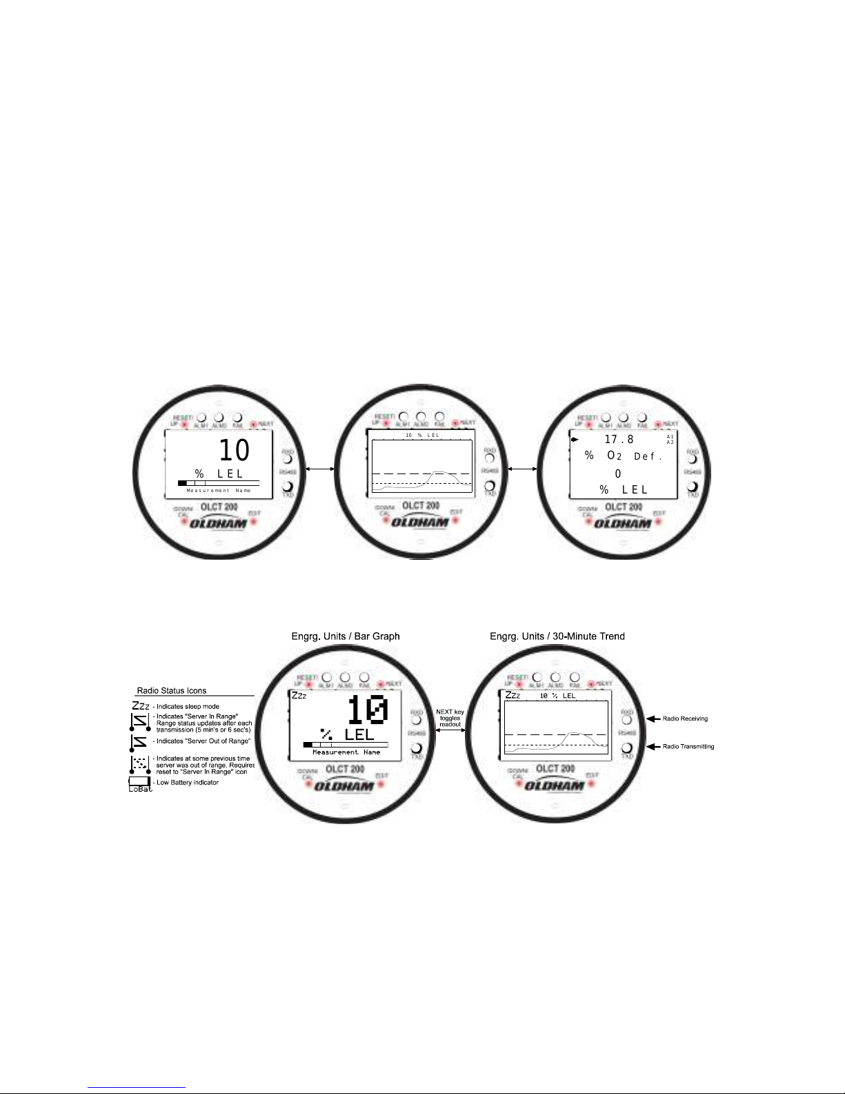
The OLCT 200 is a single or dual channel fixed-point monitor designed to provide
continuous monitoring of hazardous gases in the workplace. 2-wire and wireless
models are only single channel. Monitored values are displayed in their engineering
units as well as graphically as a bar graphs or 30-minute trends (Figure 2.1). Input
types include Electrochemical toxic / oxygen sensors, catalytic bead combustible
sensors, Infrared sensors, as well as Photoionization Detection (PID) sensors.
Sensors supplied by the factory include an 8-wire Smart Sensor interface capable of
configuration data uploads to the OLCT 200. Its advanced microcontroller electronics
and superior graphic LCD operator interface offers enhanced diagnostics and fault
analysis not possible in competing products. The wired OLCT 200 models provides a
standard 4-20 mA output signal for connection to control systems or other alarm
instrumentation. Available options include an Alarm Relay / RS-485-Modbus board, an
Isolated 4-20mA output board, and a HART Communication board. Wireless models
do not accept additional option boards. Non-volatile memory retains all configuration
data during power interruptions. The magnetic, non-intrusive calibration can be easily
performed by one person without opening the enclosure. A standard “real time clock &
calendar” feature allows data logging of calibrations and alarm events for recall to the
LCD readout or over the serial port.
The OLCT 200 wireless models functions on license free 900MHZ or 2.4GHZ wireless
Client / Server networks. Wireless data can be directly transmitted to Oldham WX4,
WX16 and WX64 Controllers. Controllers must be equipped with the matching RF
wireless modem and appropriate antenna to receive the transmissions.
Toxic and oxygen monitors are capable of 2-wire 4-20mA operation (section 2.6.1)
when the alarms / Modbus option and LCD backlight are not required. Catalytic LEL,
Infrared, and PID sensors, or addition of any option board, require the 10-0233 I/O
Power Supply board providing 3-wire 4-20mA operation (section 2.6.3).
Only periodic calibration checks are needed to assure dependable performance.
Operator interface is very intuitive with the LCD displaying data both graphically as bargraphs / trends and in engineering units (Figure 2-1). Additional features include:
Page 10
OLCT 200 User Manual | 10
No potentiometer or jumper settings required. All setup is with menus accessed via the
LCD / magnetic keypad operator interface without opening the enclosure.
Field adjustable alarm levels may be high, low, fault, fail-safe, latching and
acknowledgeable.
New alarms cause front LED’s to flash and become steady after acknowledge.
CAL MODE advises when to apply gas during calibrations
One half hour trend screen shows rate of change of gas exposures
Sensor life bar-graph updates after each SPAN calibration.
Modular design affords efficient installation and plug in sensors allow changing target
gases after installation
New smart sensors are recognized by the OLCT 200 and prompts users to either
upload new configuration data or continue with data from the previous smart sensor.
Missing Sensors trip the “FAIL” alarm.
Sensors are industry proven for fast response and long life.
On screen radio status icons indicate “Server In Range”, “Server Out of Range”, Server
Previously Out of Range” and “Low Battery” conditions.
NEXTUP/
EDITDOWN/CAL
TXD
RXD
RS485
ALM1 ALM2 FAIL
ALM RST
% O
2
De f .
Dual Channel Split Screen
(Dual Sensor Mode Only)
% L E L
17 . 8
0
A1
A2
NEXTUP/
EDITDOWN/CAL
TXD
RXD
RS485
ALM1 ALM2 FAIL
ALM RST
10 % L E L
Engrg. Units / 30-Minute Trend
NEXTUP/
EDITDOWN/CAL
TXD
RXD
RS485
ALM1 ALM2 FAIL
ALM RST
Me a s u r eme n t Na me
% L E L
10
Engrg. Units / Bar Graph
NEXT key
toggles
readout
NEXT key
toggles
readout
Figure 2-1a: Data Displays – 2 Wire and 3 Wire Models
Figure 2-1b: Data Displays – Wireless Models
Page 11

11
OLCT 200 User Manual | 11
2.2 Ratings and Certifications
Wired Models
CSA certified for Division 1 & 2 hazardous area installations for explosion proof Class 1
Groups B,C,D, and intrinsically safe (OLCT 200/EC 2-wire loops only) Class 1 Groups
A,B,C,D. Also see sections 2.7, 2.7a & 2.8. Designed to meet CSA C22.2 No.152 for
Combustibles Monitors and ISA 92.0.01 Part 1 for Toxic Monitors.
Wireless Models
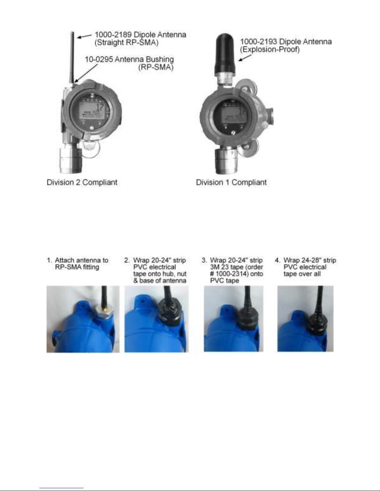
The enclosure is NRTL certified for Division 1 hazardous area installations for
explosion-proof Class 1 Groups B,C,D (see Figure 2-2c). The OLCT 200 is designed
to meet ISA 92.0.01 Part 1 for Toxic Monitors. The 10-0295 antenna fitting has an RPSMA connector and is suitable for Division 2 classified areas. An optional 1000-2193
antenna is also available for Division 1 classified areas. Figure 2-8 shows both
antenna styles.
2.3 Sensor Location
Factors such as air movement, gas density in relation to air, emission sources and
environmental variables affect correct sensor location. Air movement by fans,
prevailing winds and convection should be carefully evaluated to determine if a leak is
more likely to raise gas levels in certain areas within the facility. Vapor density of a gas
determines if it will rise or fall in air when there are no significant currents. Lighter than
air gases should have the monitors mounted 12 – 18 inches (30 – 45 centimeters)
above the potential gas leak and heavier than air gases should be this distance below.
Even though the OLCT 200 is designed for rugged service, sensors should be
protected from environmental damage from water, snow, shock, vibration and dirt.
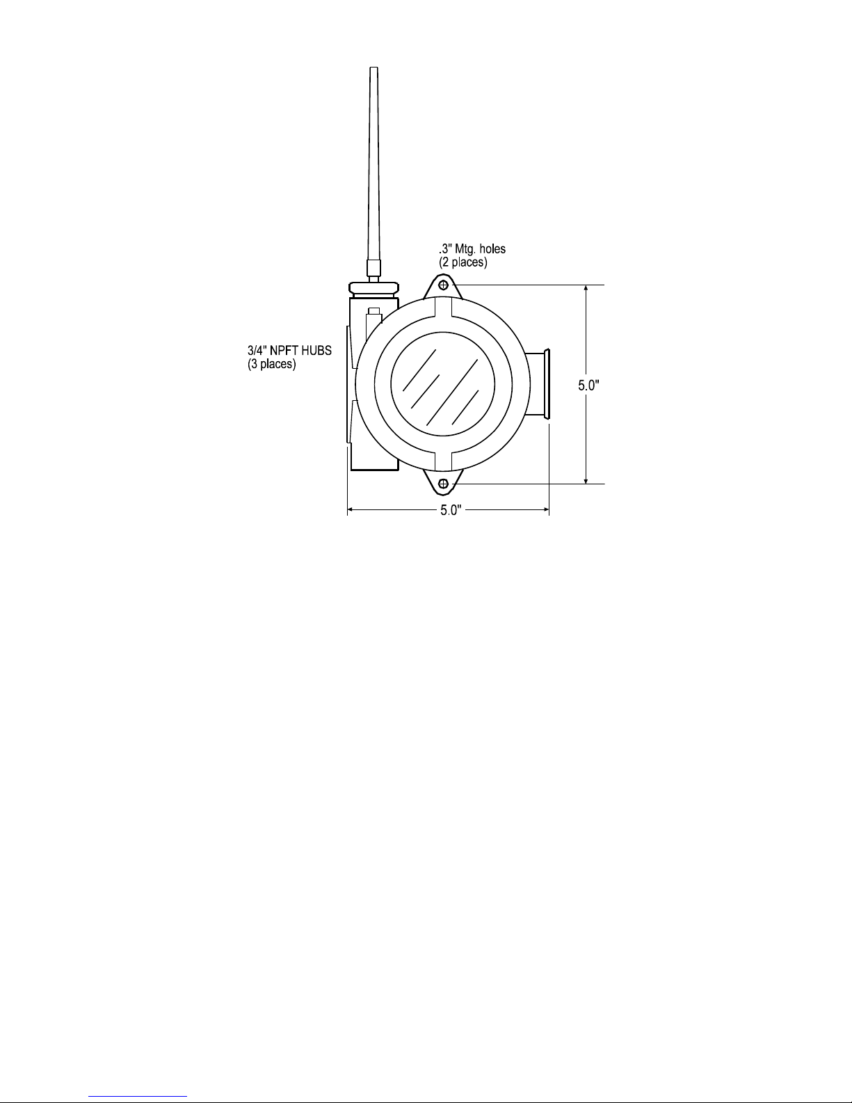
2.4 Mounting the Enclosure
The OLCT 200 standard enclosure is a cast aluminum explosion-proof (NEMA 7)
enclosure as shown in Figure 2-2. Figure 2-2a shows dimensions with the dual local
sensor ‘Y’ included. Figure 2-2c shows the wireless model. For wireless models, the
wireless antenna should typically be mounted with “line of sight” access to the
controller’s base station antenna. If a good “line of sight” angle is not possible the
OLCT 200 will usually still function properly at ranges up to 1500 feet but obstructions
should be kept to a minimum.
Page 12

OLCT 200 User Manual | 12
Figure 2-2a: OLCT 200 Explosion-Proof Housing
Figure 2-2b: OLCT 200 Explosion-Proof Housing with Dual Sensor Head Adaptor
¾" N.P.T. Hub
2 Places
4.61
8.0
Universal
Sensor Head
.25" Dia.
2 Places
5.50
5.3
Dimensions in inches
0010-1200 “Y” Fitting not available
on ATEX compliant model
Page 13
13
OLCT 200 User Manual | 13
Figure 2-2c: OLCT 200 Wireless Explosion-Proof Housing
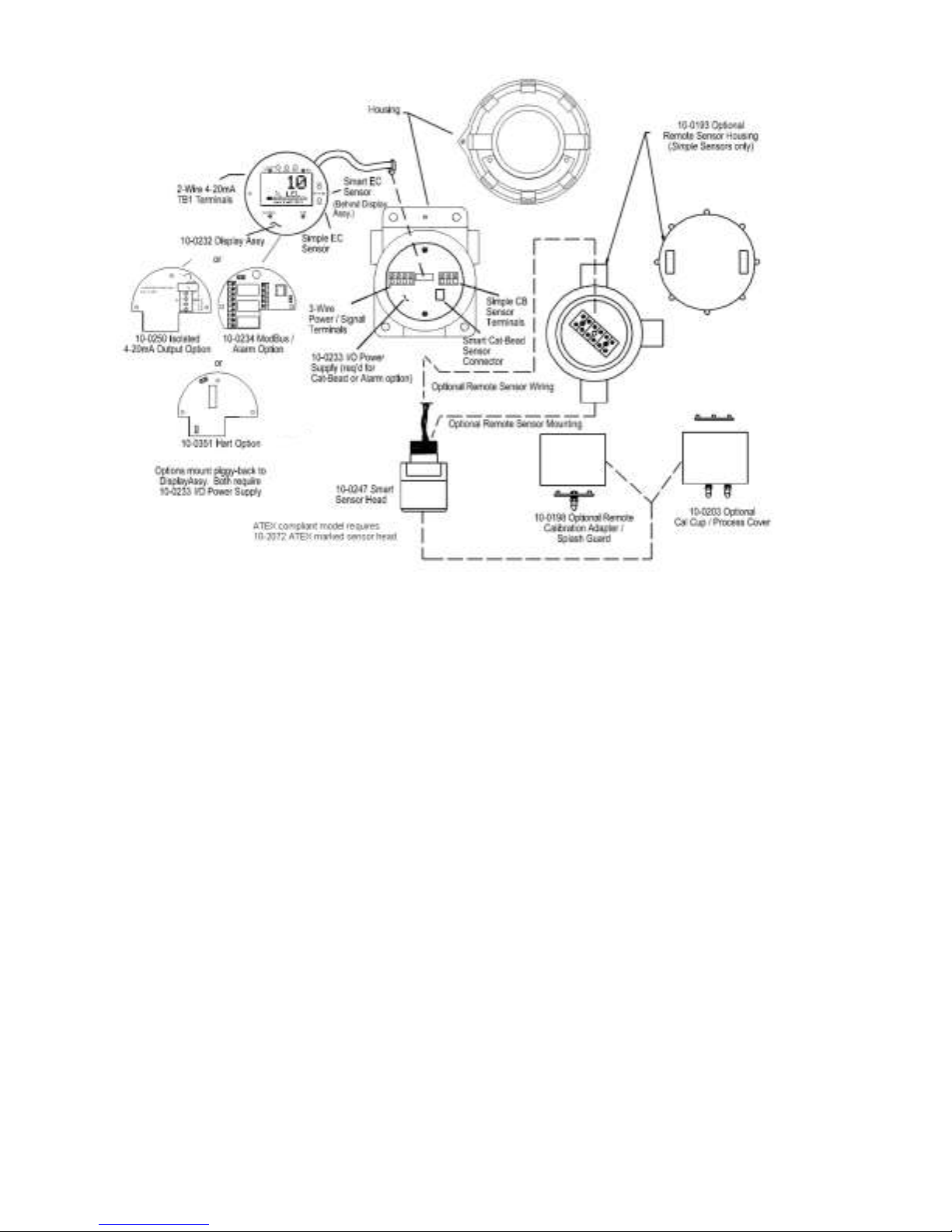
Modular design simplifies the installation of the OLCT 200 (Figure 2-3). A top Display
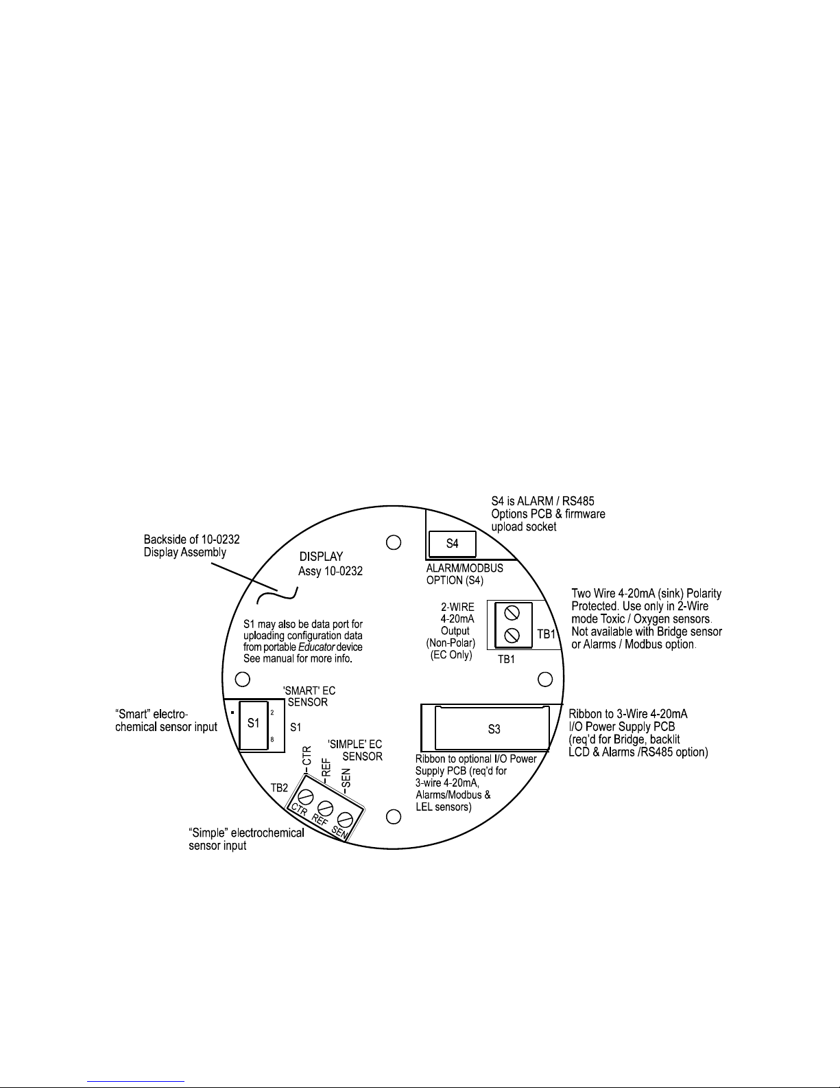
Assembly is mounted with captive thumbscrews and is easily removed to access fieldwiring terminals. An optional 10-0234 Alarms/Modbus board mounts piggyback to the
back of the Display Assembly. Wiring from toxic or oxygen sensors terminates at the
10-0232 Display Assembly along with 2-wire 4-20mA signal wires. This Display
Assembly is the only PC board supplied with toxic / oxygen OLCT 200s not requiring
relays, RS-485 Modbus, HART or LCD backlight. The optional bottom 10-0233 I/O
Power Supply board generates voltages needed for LCD backlight, relays, RS-485
Modbus, HART and Bridge sensor and is required with any of these I/O functions. The
enclosure is equipped with two threaded 3/4 inch NPT conduit fitting outlet and predrilled mounting flanges.
WARNING: Qualified personnel should perform the installation according to applicable
electrical codes, regulations and safety standards. Insure correct cabling and sealing
fitting practices are implemented. Do not aim the sensor pointing upward. Install the
OLCT 200 to a wall or bracket using the predrilled mounting flanges with I.D. 0.25 on
5.5 inch centers (Figure 2-2). If conduit is rigid and able to support the weight of the
OLCT 200, the mounting bolts may be omitted.
CAUTION: The sensor should never be installed pointing upwards.
Page 14
OLCT 200 User Manual | 14
Figure 2-3a: Outline Drawing – OLCT 200 Wired Models
Page 15
15
OLCT 200 User Manual | 15
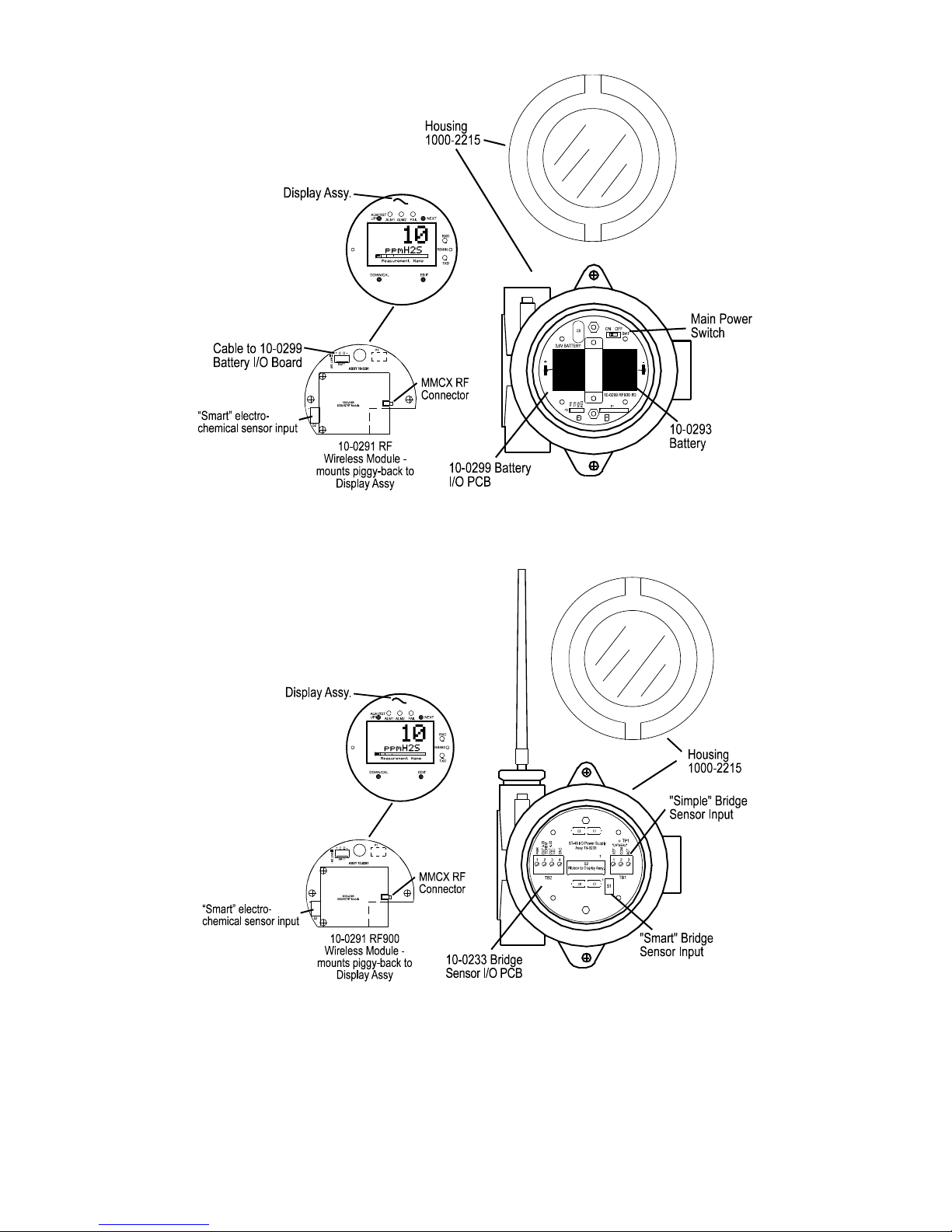
Figure 2-3b: Outline Drawing – OLCT 200 Battery Powered Wireless Models
Figure 2-3c: Outline Drawing – OLCT 200 10-3VDC Powered Wireless Models
Page 16

OLCT 200 User Manual | 16
2.4.1 10-0322 Magnetic Mounting Option
The 10-0322 Magnetic Mount securely attaches the assembly to solid steel structure
that is at least 6 inches wide.
2.5 System Design Specifications
Supply Voltage:
2 Wire Model
3 Wire Model
10-30VDC
Wireless Model
Battery Powered
Wireless Model
10-30VDC
10-30VDC
10-30VDC
Integral nonrechargeable 3.6volt
19AH lithium D cell
battery.
Replacement P/N
10-0293.
Power Consumption:
2 Wire Model
3 Wire Model
10-30VDC Wireless
Model
Battery Powered
Wireless Model
25mA max @
24VDC
100mA @ 24VDC
with 0.5watt sensor.
Relays: +40mA per
relay (120mA for
three energized
relays)
RS-485: +20mA
<20mA - “sleep”
mode
60mA – “receive
beacon” mode
Up to 1amp – 1
watt “transmit”
mode. Transmit
power can be set
from 10mW – 1W.
<2mA - “sleep”
mode
40mA – “receive
beacon” mode
Up to 1amp – 1
watt “transmit”
mode. Transmit
power can be set
from 10mW – 1W.
Loop Resistance at nominal 24 VDC power:
2 Wire Model
3 Wire Model
10-30VDC Wireless
Model
Battery Powered
Wireless Model
650 ohms
750 ohms
n/a
n/a
Memory:
Non-volatile E2 memory retains configuration values in the event of power outages.
Page 17

17
OLCT 200 User Manual | 17
Relays (Optional):
Three configurable form C (SPDT) relays rated for 5 amp at 30 VDC or 240 ~VAC
RESISTIVE.
Relay 1 and Relay 2 level alarms are configurable for HIGH or LOW trip, for normally
energized (Failsafe) or normally de-energized and for latching or non-latching.
Relay 3 is always normally energized for failsafe operation so loss of power to the
OLCT 200 will be indicated as a “FAULT” condition.
CAUTION: Relays are rated for RESISTIVE loads. Inductive loads, such contactor
coils or motors may cause contact arcing, which emits RFI into the sensor signals.
Use appropriate snubbers and MOV’s across inductive loads and keep wiring away
from signal wires.
Wireless Specifications:
900MHz Models
2.4GHz Models
Transmit (TX)
Power
30dBm at 1W power. Transmit
power may be set from 10mW
to 1W.
50mW
Receive (RX)
Sensitivity
-100dBm
-90dBm
Radio Frequency
Hopping between 902 –
928MHz.
Hopping between 2.4 – 2.5
GHz
2.6 Field Wiring Installation
4-20mA Transmission Range Info:
The distance 4-20 mA signals can travel is dependent upon several factors including
the cable gauge, DC power supply voltage level and impedance of the input of the
receiving device. Assuming a nominal 24 VDC power supply, maximum total loop
resistance is 650 ohms in the 2-wire mode.
Note: WX16 Controllers have 4-20mA input resistance of 100 ohms.
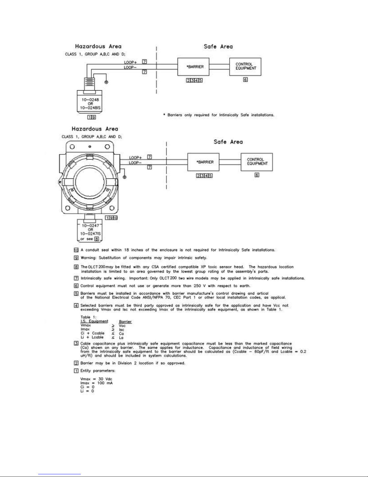
2.6.1 2-Wire 4-20mA Intrinsically Safe & Explosion Proof Installations
OLCT 200’s equipped with 10-0247 sensor heads are NRTL (Nationally Recognized
Testing Lab) certified as suitable for both intrinsically safe and explosion proof
installations. OLCT 200’s equipped with 10-0247IS sensor heads (XP flame arrestor is
not installed to allow monitoring of highly reactive gases such as Hydrogen Chloride or
Ammonia) are NRTL certified as suitable for intrinsically safe installations. All OLCT
200’s are NRTL certified for explosion proof installations as long as the sensor head is
CSA certified as explosion proof. Follow instructions on Installation Drawing # 11-0100
in section 2.6.2 for correct intrinsically safe installations.
Description:
The 2-wire current sinking transmitter is the easiest and most economical to install
since there are only two wires. All of the power needed comes from the current loop
Page 18
OLCT 200 User Manual | 18
and wire sizes may be smaller. However, only very low power applications are eligible
for such transmitters. The OLCT 200 Display assembly shown in Figure 2-4 consumes
<2.5 mA of quiescent current. Toxic and oxygen electrochemical sensors generate
their own signals and therefore require no additional current. If a 4-20mA output is all
that is required for toxic / oxygen measurements (no LCD backlight, alarms or RS-485)
the OLCT 200 may be used in the 2-wire mode.
CAUTION: It is important to understand the receiver, or controller device must supply
the loop power in 2-wire 4-20mA modes. Be sure the receiver to be used supports this
type of operation.
Instructions:
Unscrew the cover on the OLCT 200 explosion-proof enclosure. Loosen the 2
thumbscrews holding the display assembly in place and remove it. A small sensor
cable is attached with sufficient length to allow access to the back of the display
assembly where 2 position TB1 is located. Route the receiver wires through the
conduit entry and connect to TB1. Steering diodes in the OLCT 200 2-wire 4-20mA
output automatically correct for polarity so positive and negative are interchangeable.
Reassemble the OLCT 200. Follow the procedures and recommendations in the
receiver manual to complete the installation. Be sure the OLCT 200 enclosure and
conduit are properly grounded. Apply loop power by appropriately powering the
receiver device (DCS, PLC, Controller, etc) and the OLCT 200 should function.
Proceed to section-3.
Figure 2-4: 10-0232 Display / 2-Wire 4-20mA Assembly
Page 19
19
OLCT 200 User Manual | 19
2.6.2 Installation Drawing # 11-0100
Page 20

OLCT 200 User Manual | 20
2.6.3 3-Wire 4-20mA Mode Installation
CAUTION: OLCT 200’s equipped with the 10-0233 I/O Power Supply board only
operate as 3 or 4-wire 4-20mA transmitters and are not compatible with 2-wire
intrinsically safe installations (see sections 2.6.1 and 2.6.2). Such units should not be
combined with 10-0247IS Sensor Heads without flame arrestors unless the area is
classified as non-hazardous.
OLCT 200’s equipped with the 10-0233 I/O Power Supply and 10-0234 Alarms /
Modbus option are NRTL certified as suitable for Div 1 & 2 Groups B,C,D explosion
proof installations with the 10-0247 or with any sensor head with an equivalent CSA
certification.
Description:
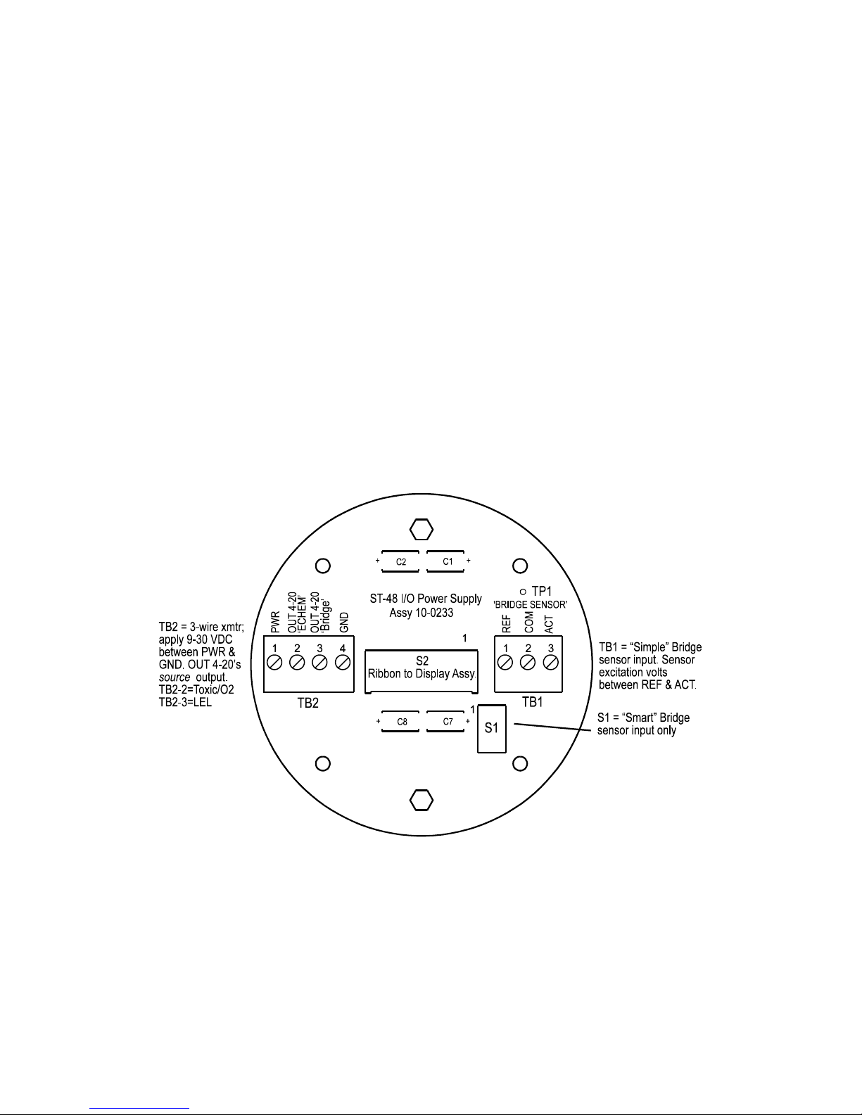
3-wire sourcing transmitters require an additional dedicated 24 VDC wire. The 4-20mA
loop current is then delivered, or sourced, from the transmitter output and the receiver
device must not provide 24 VDC from its input terminal. When the OLCT 200 is
equipped with the bottom 10-0233 I/O Power Supply board shown in Figure 2-5, the 2wire 4-20mA output is disabled and one of the 10-0233’s 3-wire outputs must be used.
TB2 terminal 2 is for ECHEM toxic / oxygen 3-wire 4-20mA output signals and TB2
terminal 3 is for LEL 3-wire 4-20mA output signals.
Instructions:
Unscrew the cover on the OLCT 200 explosion-proof enclosure. Loosen the 2
thumbscrews holding the display assembly in place and remove it. A small ribbon
cable is attached with sufficient length to allow access to the I/O PCB mounted in the
bottom of the enclosure (Figure 2-5). Power and signal connections are to TB2 where
24 VDC, Signal and Common wires must be connected. A blocking diode protects the
OLCT 200 if polarity of the power supply is reversed but it will not operate.
Reassemble the OLCT 200. Follow the procedures and recommendations in the
receiver and power supply manuals to complete the installation. Be sure the OLCT
200 enclosure and conduit are properly grounded. Apply power and the OLCT 200
should function. Proceed to section-3.
Page 21
21
OLCT 200 User Manual | 21
Figure 2-5: 10-0233 I/O Power Supply / 3-Wire 4-20mA Assembly
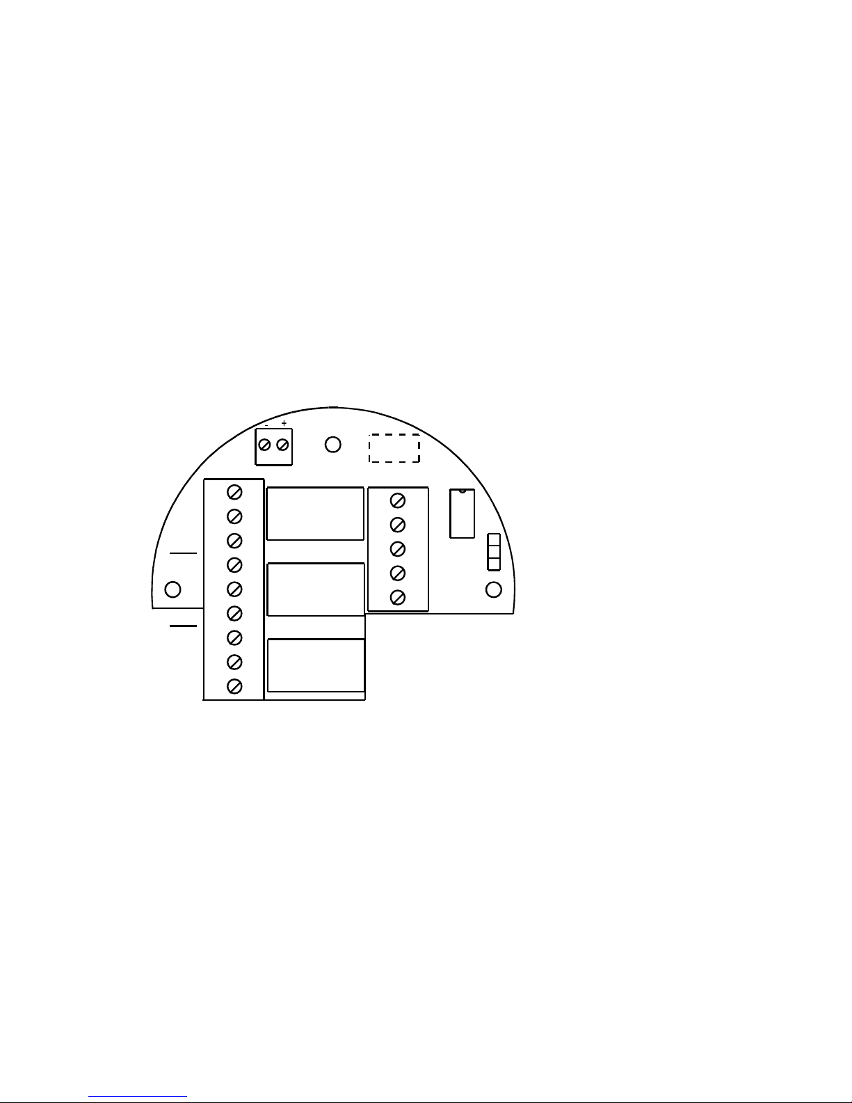
2.6.4 Wireless Model Installation
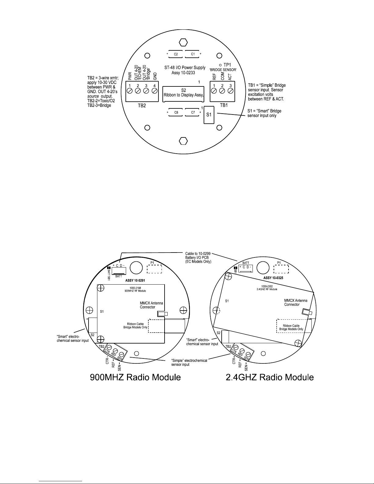
2.6.4.1 OLCT 200 RF Modules and Wiring
The OLCT 200’s radio module mounts “piggy back” to the back of the Display
assembly as shown in Figure 2-6. The module’s MMCX RF connector connects to the
antenna fitting’s pigtail coax cable. OLCT 200 wireless 10-30VDC models have a
ribbon cable connecting to the 10-0233 I/O PCB.
Figure 2-6: 10-0291 900MHZ / 10-0325 2.4GHZ RF Modules
Page 22
OLCT 200 User Manual | 22
OLCT 200 10-30VDC wireless Transmitters may accept electrochemical, catalytic
bead, PID, or IR sensors but wiring terminates differently for each. Electrochemical
sensor wiring connects to the back of the Display assembly as shown in Figure 2-6.
Catalytic Bead, PID, and IR sensor wiring connects to the I/O board as shown in Figure
2-7.
For OLCT wireless 10-30VDC powered models, connect 10-30 VDC between terminals
1 & 4 of TB2 (+ wire on 1 and 0V wire on 4) as shown in Figure 2-7. Wireless models
also transmit a sourcing 4-20mA output (electrochemical sensor output on TB2-2 and
bridge sensor outputs on TB2-3).
Instructions:
Unscrew the cover on the OLCT 200 explosion-proof enclosure. Loosen the 2
thumbscrews holding the display assembly and remove it. A small ribbon cable is
attached with sufficient length to allow access to the I/O PCB mounted in the bottom of
the enclosure (Figure 2-7). Power and signal connections are to TB2 where 24 VDC,
Signal and Common wires must be connected. A blocking diode protects the OLCT
200 if polarity of the power supply is reversed but it will not operate. Reassemble the
OLCT 200. Follow the procedures and recommendations in the receiver and power
supply manuals to complete the installation. Be sure the OLCT 200 enclosure and
conduit are properly grounded. Apply power and the OLCT 200 should function.
Proceed to section-3.
Figure 2-7: 10-0233 I/O Power Supply / 3-Wire 4-20mA Assembly
2.6.4.2 Antenna Transmission Range
The distance radio signals can travel is dependent upon several factors including
antenna design, transmitter power and Freespace losses. In order for a wireless link to
Page 23

23
OLCT 200 User Manual | 23
work, the available system operating margin (TX power - RX Sensitivity + Antenna
gains) must exceed the Freespace loss and all other losses in the system. For best RF
line-of-site, the combined height of both antennas must exceed the Fresnel zone
diameter (see below).
Dist. between ant's Fresnel zone diameter Freespace loss (dB)
1000 ft (300 m) 16 ft (4.9 m) 81
1 Mile (1.6 km) 32 ft (9.7 m) 96
5 miles (8 km) 68 ft (20.7 m) 110
10 miles (16 km) 95 ft (29 m) 116
Example:
The 900MHZ radio modem has the following parameters:
Maximum RF TX power setting = 30 dBm (1 Watt)
RF RX sensitivity = -100 dBm (this is a constant)
Antenna gain (standard equipped dipole) = 2.1dBi x 2 = 4.2dBi
So the system operating margin is 30 - (-100) + 4.2 = 134.2 dBm. This is enough to
transmit 10 miles if freespace was the only loss in the system. For this to be the case,
the antennas must be mounted with a combined height greater than 95ft above all
obstructions (including the ground) to keep the fresnel zone clear. In practice however,
there are many losses in the system besides just freespace and it is recommended
there be at least 20dB extra system operating margin.
RF “Rules of Thumb”
Doubling the range with good RF “Line of Site” (LOS) requires an increase of
6 dB.
Doubling the range without good RF LOS requires an increase of 12 dB.
2.6.4.3 Antenna Selection & Location
A site survey using an RF spectrum analyzer and test radios is highly recommended.
The location of the antenna is very important. Ensure the area surrounding the
proposed location is clear of objects such as other antennas, trees or power lines
which may affect the antenna’s performance and efficiency. It is also vital that you
ensure the support structure and mounting arrangement is adequate to support the
antenna under all anticipated environmental conditions. The choice of appropriate
mounting hardware is also important for both minimizing corrosion and maintaining site
performance.
Most installations utilize locally mounted dipole antennas as shown in Figure 2-8. An
option is available for a 6 foot riser to increase the height of the antenna 6 feet above
the OLCT 200. Extreme cases may require special order of directional antennas
mounted in such a way to allow aiming towards the base station antenna. Minimize
obstructions between the OLCT 200 and the base station antenna.
Page 24
OLCT 200 User Manual | 24
Figure 2-8: Local Antennas (900MHZ Shown)
2.6.4.4 Water Proofing Antenna Connections
Waterproof all outdoor coax connectors using a three layer sealing process of initial
layer of adhesive PVC tape, followed by a second layer of self-vulcanizing
weatherproofing tape such as 3M 23 (order # 1000-2314), with a final layer of adhesive
PVC tape (see Figure 2-9).
Figure 2-9: Water Proofing Antenna Connections
2.6.4.5 System Grounding
Direct grounding of the OLCT 200 enclosure via a good electrical connection to a welldesigned grounding system is essential. This will protect your system, reduce the
damage that can occur during lightning strikes and reduce noise.
Page 25
25
OLCT 200 User Manual | 25
2.7 Alarms / RS-485 Modbus 10-0234 Option Installation
Description:
The optional 10-0234 Alarms/RS-485 Modbus board supplies two level alarm relays, a
FAULT relay and an RS-485 Modbus RTU slave port (Figure 2-10). This board is
“piggybacked” behind the 10-0232 Display Assembly (Figure 2-3). Addition of this
option requires 3-wire mode 4-20mA operation and thereby requires the 10-0233 I/O
Power Supply board (Figure 2-5). This is since relays and RS-485 circuits require
much more power than 2-wire 4-20mA loops can deliver.
CAUTION: Alarm relays have dry contacts and power must be supplied from an
external source. Contacts are rated for RESISTIVE loads! Inductive loads, such as
contactor coils or motors, may cause contact arcing, which shortens life and emits RFI
into the sensor signals. Use appropriate arcing snubbers and MOV’s across inductive
loads and keep wiring away from signal wires. External wiring to TB3 (Remote Alarm
Reset) should be shielded and protected from noise spikes to prevent false Alarm
Reset.
Figure 2-10: 10-0234 Alarm Relays / Modbus Option
Instructions:
Unscrew the cover on the OLCT 200 explosion-proof enclosure. Loosen the two
thumbscrews holding the display assembly in place and remove it. A small ribbon
cable is attached with sufficient length to access the back of the Display assembly
where the Alarms/RS-485 Modbus board option is located. It is possible to use only
the relays, only RS-485, or use both. Relay terminals are labeled NO (normally open),
NC (normally closed) and C (common or the pole). These designators correspond to
the shelf, or de-energized, state of the relays. The FAULT relay is always failsafe,
meaning it is energized when there is not a fault condition and therefore its action is
reverse of the designators.
7
TB2
TB1
TB3
K2
K3
K1
Remote Alarm Reset
ST-48 Alarm / ModBus Option
Assy: 10-0234
1
C
NC
NO
C
NC
NO
C
NC
Relay 1
(K1)
Relay 2
(K2)
Relay 3
(K3)
2
3
4
5
6
8
9
NO
1
2
3
4
5
P1
J1
U1
A (Installs RS-485 Terminating Resistor)
B (Omits RS-485 Terminating Resistor)
A
B
S
A
B
1
RS-485 ‘A’ & ‘B’ terminals are
connected internally for easier
IN / OUT cabling.
‘S’ is “no connect” for shield
to continue.
Page 26

OLCT 200 User Manual | 26
RS-485 Modbus networks should be wired as shown in Figure 2-11. Each OLCT 200
connected represents an RTU and must have a unique RTU address. RTU addresses
are assigned in the Modbus setup menu described in section 4.10. Cabling must be a
“daisy chain” as opposed to a “star” pattern for reliable operation. The “end of line” unit
should have J1 installed in the ‘A’ position for terminating resistor installation. All
others should have J1 in the ‘B’ position. Front panel Rx / Tx LEDs are helpful
troubleshooting tools.
Figure 2-11: RS-485 Modbus Wiring
2.8 Isolated 4-20mA Output 10-0250 Option
Description:
The optional 10-0250 Isolated 4-20mA option (Figure 2-12) provides dual 4-20mA
outputs that are electrically isolated from sensor inputs and the 24 VDC power source.
Each 4-20mA output share the same common terminal and are not isolated from each
other. This board is “piggybacked” behind the 10-0232 Display Assembly (Figure 2-3).
Addition of this option requires 4-wire mode 4-20mA operation and thereby requires the
I/O Power Supply board (Figure 2-5).
Page 27

27
OLCT 200 User Manual | 27
Figure 2-12: 10-0250 Isolated 4-20mA Output Option
2.9 HART Communication 10-0351 Option
Description:
The optional 10-0351 HART modem board, figure 2-13, supplies ability to access and
alter process variables of the OLCT 200 using a HART handheld device. This board is
stacked behind the 10-0232 Display Assembly. Addition of this option requires 3-wire
mode 4-20mA operation and thereby requires the 10-0233 I/O Power Supply board.
This is since the modem’s driver circuits require much more power than 2-wire 4-20mA
loops can deliver. When installed in an OLCT 200 transmitter, power and common are
run to the I/O board and TB1 supplies 4-20 mA output. Common on the HART modem
and the I/O board are tied together.
In most applications the power is supplied from the controller that is receiving the 4-20
mA output. In these applications only three wires are required since common is shared
from the I/O board to the HART modem through the ribbon cable. Power is connected
to the I/O board and the signal connected to TB1 on the HART board.
If the 4-20 mA output is going to another device other than the one that is powering it,
or the transmitter has its own local power supply, both + and – on at TB1 on the HART
board must be utilized for the 4-20 mA loop to function.
IMPORTANT
The 4-20 mA output must be loaded with at least 250 ohms of impendence for the
HART modem to transmit process variables. Some devices receiving the 4-20 mA
output have a large enough terminating resistor installed from the factory, but others
may need additional resistance added. This is accomplished by adding a resistor in
U8
TB1
P1
FUSE
Assy: 10-0250
1
2
3
4
+
+
Isolated 4-20mA Output Option
1/2A
Page 28

OLCT 200 User Manual | 28
series with the output from HART modem board, preferably at the controller end of the
current loop. Adding the additional resistor at the controller allows the HART handheld
to be connected anywhere in the loop, because it must have the full 250 ohm load after
its connection point to function properly. If the additional resistor is added at the
transmitter, in TB1, the HART handheld will only be able to access variables locally, at
the transmitter. The example in 2-15 shows a 100 ohm resistor added to the output
loop since the controller has a 150 ohm terminating resistor installed from the factory.
Figure 2-13: 10-0351 HART Modem Option
Instructions for Accessing Process Variables with HART Handheld Device
The HART handheld can access process variables from anywhere in the 4-20 mA loop
as long as the handheld device is on the modem side of the 250 ohm load. Process
variables are accessed by attaching the leads to the signal (+) and common (-) wire.
Typically the process variables are accessed either at the transmitter or at the
controller.
At the transmitter end of the 4-20 mA loop unscrew the cover on the OLCRT 200
explosion-proof enclosure. Find the two HART connection points located next to TB1
Page 29

29
OLCT 200 User Manual | 29
on the HART board and connect the leads from the Hart handheld. They can be
accessed without pulling the nest assembly out of the enclosure and are on the top
right side, just above the next button (See Figure 2.14).
+
-
Connection Points for
Connecting HART Handheld
Figure 2-14: Top View of OLCT 200 showing HART connection terminals
At the controller end, connect the HART handheld directly across the signal and
common wires coming from the HART modem. In applications that utilize WX series
controllers, the terminals are labeled HI and LO with HI being the signal and LO being
common.
Figure 2-15: Example of OLCT 200 HART Wiring
Page 30

OLCT 200 User Manual | 30
2.10 Sensor Installation
The OLCT 200 Smart Sensor interface uses proven sensor technology but has taken
this technology a step further. A tiny memory IC is incorporated into OLCT 200 factory
supplied Smart sensors allowing them to contain the entire database of OLCT 200
parameters onboard the replaceable Smart Sensor assembly (Figure 2-16).
Smart sensors plug into the 10-0247 Smart Sensor Head that connects to OLCT 200
electronics with its 8-conductor Smart Sensor Interface cable (Figure 2-16).
CAUTION: 10-0247 Smart sensor heads with electrochemical toxic / oxygen sensors
must connect to S1 located on the back of the 10-0232 Display Assembly (Figure 2-3).
10-0247 Smart sensor heads with catalytic bead, Infrared, or PID sensors must
connect to S1 located on the optional I/O PCB assembly (Figure 2-5).
Figure 2-16: 10-0247 Smart Sensor Head Assembly
Smart Sensors are automatically recognized by the OLCT 200. The Smart Sensor
identification screen in Figure 2-17 is shown after power-up, upon installation of a new
smart sensor or by viewing INPUT type in the SENSOR SETTINGS / INFO menu
(section 5-5).
Figure 2-17: Smart Sensor Info / ERROR Screens
SMA RT SE NSOR
T y p e : Ca t - Be a d
Sp a n : 10 0
Z e r o : 0
SN: x x x x x x
Bo r n On : 0 1/ 2 8 / 0 4
L a s t Ca l : 0 4 / 0 5 / 0 4
A NY k e y t o Ex i t
ER ROR CODE 0 1
I n c o r r e c t Se n s o r
i n s t a l l e d . I n s t a l l
c o r r e c t s e n s o r o r
u p d a t e t r a n s mi t t e r .
SE E MA NUAL
EDI T k e y t o u p d a t e .
An y o t h e r t o a b o r t .
If installed sensor
type does not match
transmitter database
Page 31

31
OLCT 200 User Manual | 31
2.11 “Sensor Type” and OLCT 200 Signal Conditioning
Catalytic bead and electrochemical sensors obviously have different signal conditioning
requirements. In addition, same sensor types have different response coefficients,
signal strength and gain and offset requirements. The block / wiring diagram in Figure
2-18 illustrates how OLCT 200’s are able to accept many sensor types without the
need of manual potentiometers or jumpers. Smart Sensors carry this setup information
with each sensor.
Figure 2-18: OLCT 200 Block / Wiring Diagram
Page 32

OLCT 200 User Manual | 32
Page 33
33
OLCT 200 User Manual | 33
SECTION 3 - INITIAL START-UP
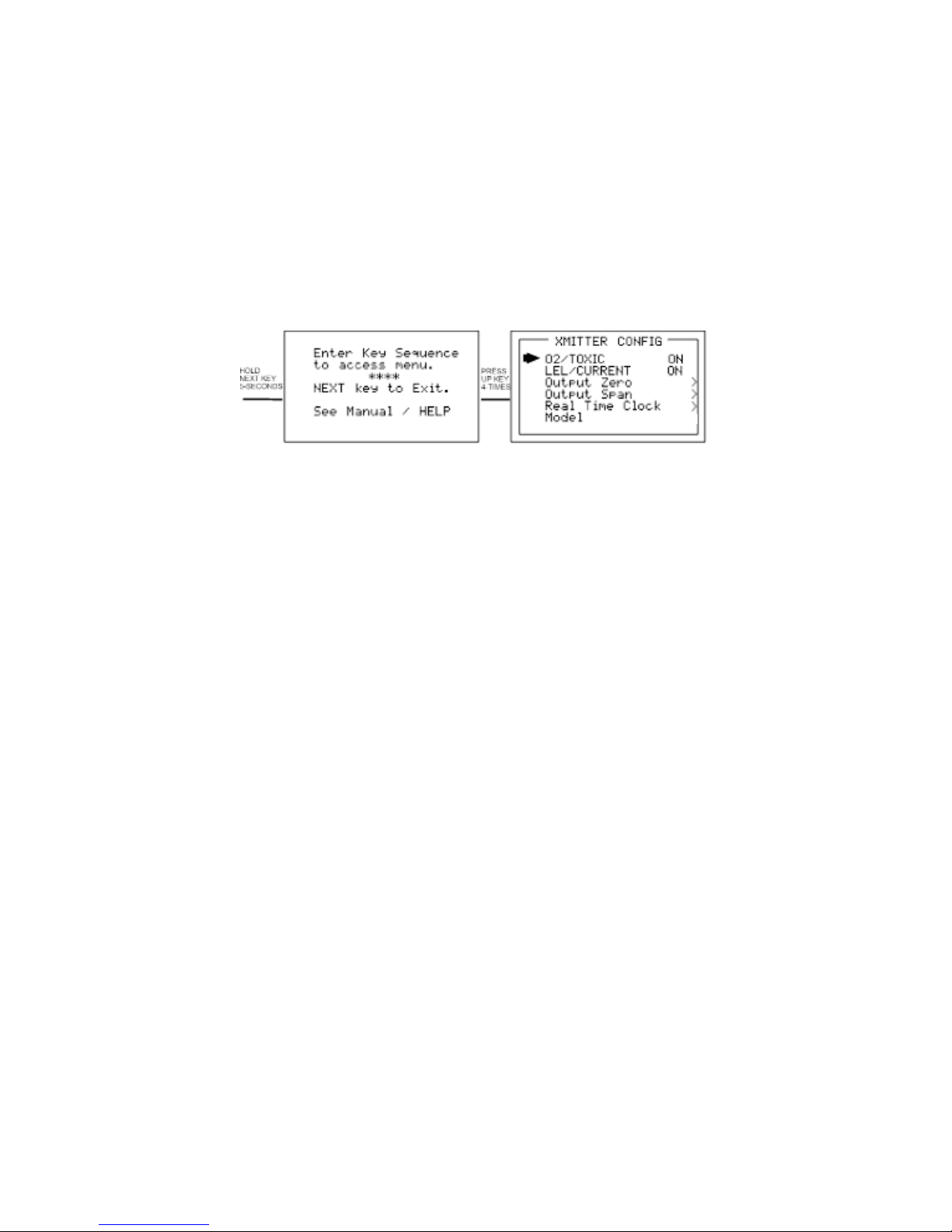
3.1 “Transmitter Configuration” Menu
Figure 3-1shows the OLCT 200 XMITTER CONFIG menu used to activate channels,
precisely calibrate 4-20mA outputs and set time / date. Its menus are set at the factory
and typically not needed by the user. To access from any data display, press and hold
the NEXT key for 5-seconds until the screen appears requesting a special key
sequence (4-UP keystrokes). Note that not all menu options will be displays for certain
models and configurations.
Figure 3-1: Transmitter Configuration Menu
3.1.1 Single / Dual Gas Monitor Configuration
2-wire 4-20mA and wireless OLCT 200’s devices support only one electrochemical
sensor. Addition of the 10-0233 Power Supply board automatically adds the catalytic
bead, IR, and PID sensor input. With the addition of the10-0233 Power Supply Board,
3-wire models have dual 4-20mA output capability. If both the O2/TOXIC and
LEL/Current menu items are ON, the OLCT 200 will function as a dual gas monitor with
both sensor inputs and 4-20mA outputs active. Either input may be turned off for
single gas EC or LEL monitors.
3.1.2 Output Zero / Output Span Trims (Wired Models Only) (Factory Preset,
Technicians only!):
The Output Zero Trim / Output Span Trim entries are digital to analog (D2A) values
that determine the OLCT 200’s final 4-20mA output. Their purpose is to provide
precise OLCT 200 4mA and 20mA outputs. To trim these values, attach a precision
milliamp meter to the OLCT 200 4-20mA output being used. Enter the correct
OUTPUT ZERO TRIM menu shown in Figure 3-2. Use the UP/DOWN keys to trim the
milliamp value to 4.00mA. Next, enter the correct OUTPUT SPAN TRIM menu and
use the UP/DOWN keys to trim the milliamp value to 20.00mA. Press the NEXT key to
exit this menu. The OLCT 200 stores these new D2A values and uses them as the 0 &
100% of full-scale endpoints.
WARNING: Target gas monitoring and alarm processing are halted during these
adjustments.
Page 34

OLCT 200 User Manual | 34
Figure 3-2: Output ZERO / SPAN Trim Menus
3.1.3 Model Name
When power is applied to the OLCT 200 it will briefly show a 10 digit ASCII model
name or company name as it starts up. The name can be edited in the Transmitter
Configuration menu by editing the Model field.
3.2 Initial Bridge Sensor Monitor Start-Up
OLCT 200 LEL Monitors that are factory equipped with Smart Bridge sensors rarely
require adjustments, other than routine calibrations, to provide accurate LEL readings.
However, after installation the following checks should be performed to insure proper
operation. In addition, alarm levels, Measurement Name ASCII fields and other
variables may require configuration by users in order to best serve their application.
3.2.1 Initial Bridge Sensor Monitor “Sensor Volts” Check
CAUTION: Sensor Volts in excess of the rated values may destroy catalytic bead
sensors. OLCT 200 sensors are rated for 2 volts.
Section 6.2 describes reading and setting “sensor volts” using the OLCT 200 LCD.
The voltage displayed on the LCD is monitored across TB1-REF and TB1-ACT on the
OLCT 200 Power Supply board (Figure 2.4) and may be confirmed with a voltmeter.
This TB-1 value is correct for locally mounted sensors only. Sensors mounted more
than a few feet away from the OLCT 200 may receive a lower voltage due to the
inherent voltage drop across sensor wiring. Remote mounted sensors must have their
sensor voltage (across ACTIVE and REFERENCE beads) measured AT THE
SENSOR end of the cable. The OLCT 200 setting will require a higher value in order
to achieve the correct voltage at the sensor. Correct sensor voltage should be
confirmed after start-up for locally and remotely mounted catalytic bead sensors.
3.2.2 Initial Bridge Sensor Monitor “Balance” Check
Catalytic bead sensors connect to a bridge circuit that may require a balance
adjustment after installation especially when the sensor is remote mounted from the
OLCT 200. Section 7.2 describes using the LCD to read and adjust BALANCE
settings. Correct BALANCE setting should be confirmed after start-up for locally and
remotely mounted catalytic bead sensors.
Page 35

35
OLCT 200 User Manual | 35
3.2.3 Initial Bridge Sensor Monitor “Span” Check
Prior to the initial Routine Sensor Calibration described in section 4.1, a coarse SPAN
gas reading verification should be performed after installation. After correct Sensor
Volts and BALANCE have been verified, apply an upscale gas value such as 50% LEL
to the sensor. The indicated value should read between 35 and 65% LEL with 50%
LEL gas applied. Larger errors may indicate incorrect sensor wiring or defective
sensor. Remember that this is only a coarse check and precision calibrations are
performed in Routine Sensor Calibrations described in the following section 4.1.
Section 7.4 describes PREAMP GAIN adjustments that may be required if full-scale
ranges are changed.
3.3 Initial Toxic / Oxygen Sensor Monitor Start-Up
OLCT 200 Toxic / Oxygen Monitors, factory equipped with Smart electrochemical
sensors, rarely require adjustments (other than routine calibrations) to provide accurate
readings. However, after installation the following checks should be performed to
insure proper operation. In addition, alarm levels, Measurement Name ASCII fields
and other variables may require attention by users in order to best serve their
application.
3.3.1 Initial Toxic / Oxygen Sensor Monitor “Span” Check
Prior to the initial Routine Sensor Calibration described in section 4.1, a coarse SPAN
gas reading verification should be performed after installation. Apply an upscale gas
value of at least 25% of full scale to the sensor. For example, if 0-100ppm H2S is the
measurement range, apply at least 25ppm but not more than 100ppm. The indicated
value should read within 15% of full scale. Remember that this is only a coarse check
and precision calibrations are performed in Routine Sensor Calibrations described in
the following section 4.1. Section 6.4 describes PREAMP GAIN adjustments that may
be required if full-scale ranges are changed.
Page 36

OLCT 200 User Manual | 36
Page 37

37
OLCT 200 User Manual | 37
SECTION 4 - OPERATING
INSTRUCTIONS
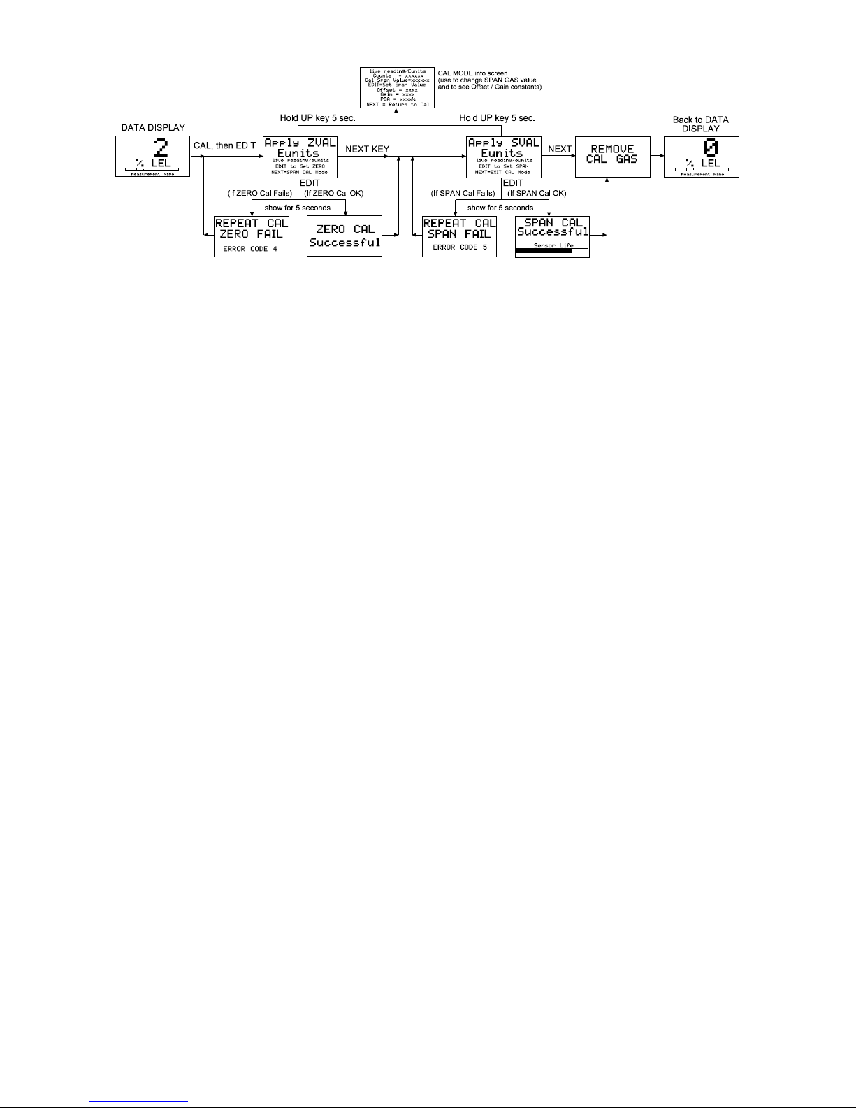
4.1 Routine Sensor Calibrations
Calibration is the most important function for insuring correct operation of the OLCT
200. The CAL MODE (flow chart shown in Figure 4-2) is designed to make calibration
quick, easy and error free. A successful ZERO and SPAN calibration requires only
four keystrokes. The 4-20mA output indicates CAL MODE by transmitting 3mA for 2wire installations and 1.5mA for 3-wire installations. The OLCT wireless model’s 10-bit
output transmit 200-1000 counts for 0-100% full scale. It indicated cal mode by
transmitting 75 counts (-15.6% FS) to receivers on the network. After the calibration is
complete, 2/3 wire models transmit 4mA during the subsequent CAL PURGE delay to
prevent external alarms during calibration. Wireless models transmit 200 counts (884
counts for oxygen) during CAL PURGE. Local OLCT 200 alarm relays (if equipped)
are inhibited during CAL MODE. CAL MODE automatically exits if no keystrokes are
detected after 5 minutes.
Follow these OLCT 200 calibration guidelines:
Calibration accuracy is only as good as the calibration gas accuracy. Oldham
recommends calibration gases with NIST (National Institute of Standards and
Technology) traceable accuracy to increase the validity of the calibration.
Do not use a gas cylinder beyond its expiration date.
Calibrate a new sensor before use.
Allow the sensor to stabilize before starting calibration (approximately 5
minutes).
Calibrate on a regular schedule. (Oldham recommends once every 3 months,
depending on use and sensor exposure to poisons and contaminants.)
Calibrate only in a clean atmosphere, which is free of background gas.
Page 38
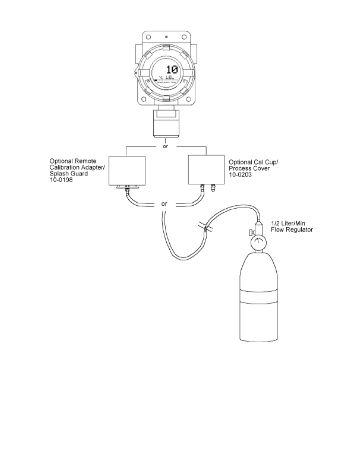
OLCT 200 User Manual | 38
Figure 4-1: Calibration Gas Input
Page 39

39
OLCT 200 User Manual | 39
Use the following step-by-step procedure to perform ZERO and SPAN calibrations.
1. To enter the CAL MODE from either data display, press the DOWN / CAL key
and within 5 seconds press the EDIT key. Note: During CAL MODE, the
follow signal is transmitted to the receiving device and signifies “CAL MODE”.
This special value is used to inhibit alarm trips at the receiver.
2 Wire Model
3 Wire Model
10-30VDC
Wireless Model
Battery Powered
Wireless Model
3mA
1.5mA
75 counts
(-15.6%FS)
75 counts
(-15.6%FS)
FOR OXYGEN (O2), SKIP STEPS 2 & 3 AND PROCEED DIRECTLY TO
THE SPAN CALIBRATION BY PRESSING THE “NEXT” KEY.
2. Using the Cal-Cup, apply a clean ZERO gas or be sure there is no
background target gas in the monitored area. After the reading is stable,
(approximately 1 minute) press the EDIT key to perform a ZERO calibration.
3. If the ZERO calibration is successful, press the NEXT key to proceed to the
SPAN check.
4. Apply the correct SPAN gas at .5 liters/min. After the reading is stable,
(approximately 1 minute) press the EDIT key to perform a SPAN calibration.
WARNING: The SPAN gas used must match the value specified since this is
what the OLCT 200 will indicate after a successful SPAN calibration. The Cal
Span Value may be edited if it becomes necessary to apply a different gas
concentration (see Cal Span Value in section 5.3).
5. If the SPAN calibration is successful, the display flashes “REMOVE CAL
GAS” and starts the CAL PURGE delay. Note: During CAL PURGE delay,
transmitters are set to 0% full scale to avoid unintended alarm events.
Oxygen monitors are set to 20.9% oxygen during this delay.
6. CAL MODE will be complete after the end of the CAL PURGE delay.
The flow chart in Figure 4-2 illustrates the above procedure. UP, CAL, NEXT & EDIT
labels indicate keystrokes using the magnetic wand. The CAL MODE information
screen (top of the chart) is available for advanced users to see Offset / Gain calibration
constants and live analog to digital converter (A/D) counts. Span Gas calibration
values may also be edited from this screen. Holding the UP key, for 5 seconds during
CAL MODE, displays this screen.
Calibration history records are logged and may be viewed in the Sensor Information
menu (see section 5-5).
Page 40
OLCT 200 User Manual | 40
Figure 4-2: Cal-Mode Flow Chart and Menus
4.2 ALARM OPERATION
OLCT 200’s have front panel LED indicators for Alarm 1, Alarm 2 and Alarm 3. An
optional 10-0234 Relay/Modbus board adds K1, K2 & K3 relays for these alarms.
CAUTION: OLCT 200 Alarm LED indicators function even without the presence of the
10-0234 Relay option. With 2-Wire 4-20mA and wireless operation, to conserve
power, alarm LED’s only flash during alarm events. With 3-Wire 4-20mA operation,
alarm LED’s flash when new, and become steady after an operator ACKNOWLEDGE -
pressing the UP/RESET key.
For OLCT 200 wireless models, “Low Battery” is indicated by an icon on the LCD and
by flashing the FAIL LED. ALL ALARM EVENTS EXCEPT FOR LOW BATTERY
INCREASE WIRELESS TRANSMISSIONS TO EVERY 6 SECONDS.
4.2.1 ALARM 3 – UNDERSTANDING FAULT / LEVEL OPERATION
The “A3” alarm is typically dedicated to FAULT conditions indicating sensor failures or
“out of measurement range” conditions. However, some applications require a third
level alarm. The A3 menu is identical to A1 & A2 and may be set to trip at an upscale
level value. A3 WILL ALSO TRIP WITH MISSING OR FAILED SENSORS
REGARDLESS OF THE LEVEL VALUE!
CAUTION: Missing or failed sensors always trip Alarm 3 (FAIL) and relay K3 (if
equipped). This is true even with A3 configured as a level alarm and it must be
accepted that A3 level alarm events might be caused by the monitored level, or, by a
missing or failed sensor. A3 and FAIL alarm conditions DO NOT cause the radio
transmission rate to increase to 6 seconds.
Page 41
41
OLCT 200 User Manual | 41
SECTION 5 - SETUP MENU
CONFIGURATION
5.1 Menus Database Configuration
All OLCT 200 configuration variables are stored in its non-volatile menu database.
Upon installation, many menu items will contain default values from the factory and
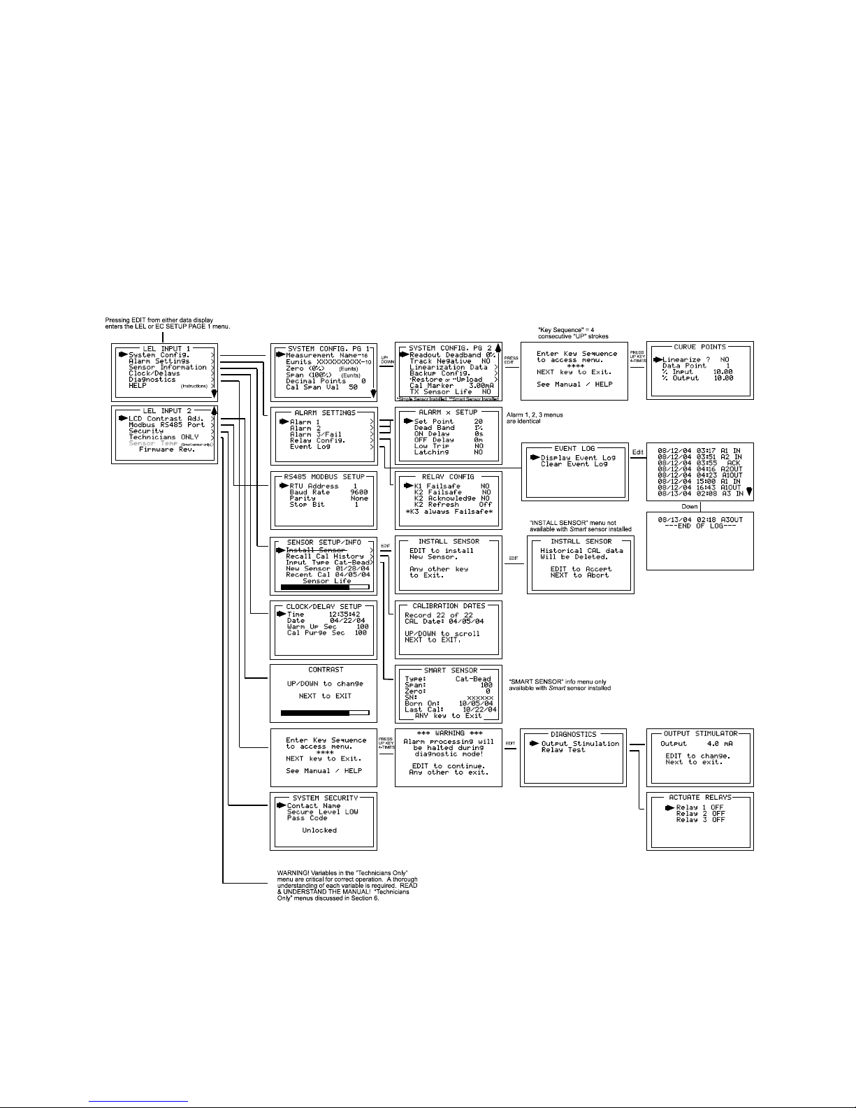
require changes to better match a user’s particular application. OLCT 200 menus may
be conFigured from the magnetic keypad in just a few minutes per transmitter. The
OLCT 200’s configuration menus are shown in Figure 5-1.
Figure 5-1a: Configuration Menu Tree- Wired Models
Page 42

OLCT 200 User Manual | 42
Figure 5-1b: Configuration Menu Tree- Wireless Models
5.2 Configuration Using the Magnetic Wand
Passing the magnetic wand past the EDIT key, from either data display, displays
SETUP PAGE 1 as shown in Figure 5-2. The UP / DOWN keys maneuver the pointer
while EDIT enters sub-levels of menu items. All SETUP menu items have at least one
page of sub-menus. Items with sub-menus are indicated by the > symbol (right hand
pointing arrow) at the end of each line. Edit menu items by pointing to them, press the
EDIT key to display the cursor, press UP / DOWN to change that character, press
NEXT to move the cursor, then press EDIT again to load the new item and remove the
cursor. Press NEXT to reverse out of the sub-menu. To view SETUP PAGE 2, press
the DOWN key with the pointer aimed at the bottom item on PAGE 1.
Page 43

43
OLCT 200 User Manual | 43
Figure 5-2a: Setup Menu Entry – Wired Models
Figure 5-2b: Setup Menu Entry – Wireless Models
5.3 System Configuration Menus
The System Config. group consists of two pages of menus as shown in Figure 5-3.
Each item’s description follows in this section.
Figure 5-3: System Config. Menus
Measurement Name may be edited to contain virtually any 16-character ASCII
field. It is typically used to describe the monitored point by user tag # or other familiar
terminology.
L E L I NPUT 2
L CD Co n t r a s t A d j .
Mo d b u s RS 4 8 5 Po r t
Se c u r i t y
T e c h n i c i a n s ONL Y
Se n s o r T e mp
F i r mwa r e R e v .
>
>
>
>
>
“Sensor Temp” menu only present
with “Arctic” smart sensor installed.
See section 7.1.
EDIT
L E L I NP UT 1
Sy s t e m Co n f i g .
Al a r m Se t t i n g s
Se n s o r I n f o r ma t i o n
Cl o c k / De l a y s
Di a g n o s t i c s
HE L P
>
>
>
>
>
>
(Instructions)
Page 44

OLCT 200 User Manual | 44
Eunits (engineering units) may have up to a 10 character ASCII field. Many common
gases have pre-configured Eunits based upon the sensor type and each may be edited
in this menu as described in Configuration Using the Magnetic Wand section 5-2.
Zero (0%) defines the reading to be displayed when 4mA (0%) is the OLCT 200
output.
Span (100%) defines the reading to be displayed when 20mA (100%) is the OLCT
200 output. The highest reading allowed is 9999 includes negative polarity sign and
one decimal point. Polarity is only indicated for negative readings.
Decimal Points sets the resolution of the LCD readings and may be for 0, 1 or 2.
Example: ZERO readings for 0, 1 & 2 DP’s respectively are 0, 0.0 & 0.00.
Cal Span Value sets what upscale value must be applied when performing Span
calibrations.
Readout Deadband allows forcing low values to continue to read zero. This is
useful when there are small amounts of background gases that cause fluctuating
readouts above zero. The highest amount of deadband allowed is 5%. The 4-20mA
output is not affected by this menu item.
Track Negative, set to NO, causes negative values to read the Zero (0%) value in
data displays. The CAL MODE readout displays negative values regardless of this
setting and negative values below the Fault set point will still cause the Fault alarm to
trip. The 4-20mA output always locks at 4mA when the reading is negative.
Linearization Data allows nonlinear signals to be linearized by entering the
correct curve into the OLCT 200 (Figure 5-4). If Linearize is set for NO, the CURVE
POINTS menu data is not used and no linearization is applied. When YES, the
CURVE POINT entries are used and a straight-line approximation is calculated
between each of the 9 entries. 0% input always provides 0% output and 100% input
always provides 100% output. To prevent accidental data entry a special keystroke
sequence, of 4 consecutive UP keys, is required to enter this menu.
Figure 5-4: Linearization Menu
En t er Ke y Se q u e n c e
t o a c c e s s me n u .
* * * *
NEX T k e y t o E x i t .
S e e Ma n u a l
L i n e a r i z e ? NO
Da t a P o i n t 1
% I n p u t 10 . 0 0
% Ou t p u t 10 . 0 0
PRESS
UP KEY
4-TIMES
CURVE P OI NT S
Page 45

45
OLCT 200 User Manual | 45
Backup Config. allows users to store the entire current OLCT 200 menu database
into non-volatile memory for restoration later if incorrect values are accidentally entered
or uploaded.
Restore Config. restores the OLCT 200 menu database to the values from the
most recent Backup Config. This menu item is only available if a smart sensor is not
installed. The special keystroke sequence of 4 consecutive UP keys is also required to
perform backup and restore operations.
Upload Sensor Data allows manually uploading the entire smart sensor database
to the OLCT 200 from the smart sensor.
Cal Marker (wired models only) allows setting the 4-20mA output value
during ZERO and SPAN calibrations at a level to prevent alarm trips by calibration
values. 3-Wire models may be set from 0 to 20mA. Quiescent current of 2-wire
models limits this setting to 3 to 20mA.
TX Sensor Life (wired models only) set for YES, causes the OLCT 200 4-
20mA output to transmit a sensor life value after successful calibrations during the CAL
PURGE delay (see section 4.1). Normal operation is the OLCT 200 transmits 4mA
during the CAL PURGE delay. But with TX Sensor Life = YES it transmits 4mA for the
first 10-seconds, then for 5-seconds transmits a value between 4mA and 5mA, with
4mA equal to 0% sensor life and 5mA equal to 100% sensor life (see Figure 5-5). The
output then returns to 4mA for the remainder of the CAL PURGE delay. For example,
if after a calibration sensor life is 75%, the OLCT 200 transmits 4.75mA during the 5second interval.
Note: TX Sensor Life should always be set for NO unless the 4-20mA receiver is
capable of interpreting the sensor life signal. The Oldham WX16 Controller is capable
of this function.
Figure 5-5: Transmit Sensor Life Timing Diagram
Page 46

OLCT 200 User Manual | 46
5.4 Alarm Settings
The Alarm Settings page has the Alarm 1, 2, 3 Setups, Relays and Event Log
submenus shown in Figure 5-6. Alarm 1, Alarm 2 and Alarm 3/Fail menus are identical
and therefore described only once in this section.
IMPORTANT: Alarm functions and their associated LED’s are active without the 100234 Relay / Modbus option installed. Alarm conditions are indicated by A1, A2, A3
LCD icons and by flashing the A1, A2 and FAIL led’s. The Event Log time and date
stamps significant events such as power applied, alarm trips sensor faults and wireless
INRange / Out of Range conditions. The wireless range icon changes to after an
Out of Range and subsequent return to InRange event. It may be reset to normal with
the Reset Range Icon menu.
AL A R M SET T I N GS
Al a r m 1
Al a r m 2
Al a r m 3 / F a i l
Re l a y s Co n f i g .
Al a r m E v e n t L o g
AL A R M x SE T U P
Se t Po i n t 2 0
De a d - Ba n d 1%
ON De l a y 0 s
OF F D e l a y 0 m
L o w T r i p NO
L a t c h i n g N O
Alarm 1, 2, 3 menus
are identical
>
>
>
>
>
REL A Y CON F I G
K1 Fa i l s a f e N O
K2 Fa i l s a f e NO
K2 Ac k n o wl e d g e N O
K2 Re f r e s h Of f
* K 3 a l wa y s F a i l s a f e *
Figure 5-6: Alarm Settings Menus
Set Point enters the engineering unit value where the alarm trips. It may be negative
and trip when monitored values fall out of range in this direction. A3 has a default
negative 5% of range Set Point with Low Trip set for YES. This makes it function as a
FAULT alarm and trip when the monitored value is more than 5% “out of range”.
Dead-Band has a minimum value of 1% and a maximum value of 10%. It is useful for
preventing alarm cycling when the monitored value is hovering around the set point.
EXAMPLE: With a range of 0-100 ppm, if Dead-Band equals 5% and the set point is
20 ppm, after tripping at 20 ppm the value must drop below 15 ppm to reset.
ON Delay allows entering a maximum 10 second delay before this alarm becomes
active. This is useful for preventing nuisance alarms caused by brief spikes beyond
the set point.
OFF Delay allows entering a maximum 120 minute delay before clearing an alarm after
the alarm condition is gone. This is useful for continuing an alarm function, such as
operation of an exhaust fan, for a period of time after the alarm condition clears.
Low Trip set to YES causes the alarm to trip as the value falls below the set point.
Page 47

47
OLCT 200 User Manual | 47
Latching set to YES causes the alarm to remain active even after the condition is gone
and only reset when the UP / RESET key is pressed from a data display.
5.4.1 Relay Configuration (if equipped)
Relay Config has the submenu shown in Figure 5-7. The optional relay PCB must be
installed to access this menu or a “HARDWARE NOT PRESENT” message appears.
Figure 5-7: Relay Config. Menu
K1 / K2 Failsafe set for YES means the relay de-energizes during alarm and energizes
with no alarm. This is useful for also signaling alarm when OLCT 200 power is lost.
K3 is a FAULT alarm and is always failsafe.
K2 Acknowledge set for YES means the UP / RESET key (RESET key during either
data display) will set K2 to the normal state EVEN when an Alarm 2 condition exists.
This is useful for silencing an audible device, driven from K2, during the alarm
condition.
K2 Refresh set for ON causes an acknowledged Alarm 2 condition to reactivate K2 if it
continues beyond the designated Refresh interval (0-99 minutes). This feature insures
against “forgotten” alarms after an Acknowledge.
5.5 Sensor Information
Sensor Information has the SENSOR SETUP/INFO menus shown in Figure 5-8
RE L AY CONF I G
K1 F a i l s a f e N O
K2 F a i l s a f e NO
K2 Ac k n o wl e d g e NO
K2 Re f r e s h Of f
* K3 a l wa y s F a i l s a f e *
Page 48

OLCT 200 User Manual | 48
Figure 5-8: Sensor Information Menus
Install New Sensor - The OLCT 200 Smart sensor interface will automatically detect
new smart sensors and this menu is therefore not available with a smart sensor
connected.
Recall Cal History recalls each successful calibration. These dates may be reviewed
by scrolling with the UP / DOWN keys.
Input Type indicates what kind of input or sensor the OLCT 200 is configured to
accept and is typically pre-configured at the factory. There are five Input Type
possibilities consisting of bridge, EC negative, EC positive, 4-20mA and Smart. Smart
sensors upload sensor type and other data to the OLCT 200 and may be viewed on the
SMART SENSOR information screen.
New Sensor displays the date when a new sensor was last installed.
Recent Cal displays the most recent calibration date.
5.6 CLOCK/DELAY SETUP
Since the OLCT 200 is equipped with a Real Time Clock & Calendar Time and Date
must be set to correctly match its location. They are set at the factory in a 24 hour
format but may require adjustment to match the location’s time & date after shipment.
Follow the procedure in Configuration Using the Magnetic Wand in section 3.3.
Warm Up and Cal Purge time delays are also available to prevent unwanted alarm
trips. Figure 5-9 shows the menu for these items.
SE N SOR S E T T I NGS / I NF O
I n s t a l l Se n s o r
Re c a l l Ca l Hi s t o r y
I n p u t T y p e S MAR T
Ne w Se n s o r 0 1/ 2 8 / 0 4
Re c e n t C a l 0 4 / 0 5 / 0 4
>
>
I N S T A L L NE W S E N S OR
E D I T t o i n s t a l l
Ne w Se n s o r .
A n y o t h e r k e y
t o Ex i t .
CA L I B RA T I ON DA T E S
Re c o r d 2 2 o f 2 2
CA L D a t e : 0 4 / 0 5 / 0 4
UP / DOWN t o s c r o l l
NE X T t o E X I T .
I N S T A L L NE W S E N S OR
Hi s t o r i c a l CA L d a t a
Wi l l b e De l e t e d .
ED I T t o Ac c e p t
NE X T t o A b o r t
EDIT
EDIT
Se n s o r L i f e
>
SMA R T SE N S OR
T y p e : C a t - Be a d
Sp a n : 10 0
Z e r o : 0
SN : x x x x x x
Bo r n On : 0 1/ 2 8 / 0 4
L a s t Ca l : 0 4 / 0 5 / 0 4
A NY k e y t o E x i t
Page 49

49
OLCT 200 User Manual | 49
Figure 5-9: Clock & Calendar / Delay Timer Menu
5.7 LCD Contrast Adj
LCD Contrast Adj. may be set for optimum viewing using the menu shown in Figure 5-
10.
Figure 5-10: LCD Contrast Adjust Menu
5.8 HELP Screen
The HELP screen contains several pages of information describing how to operate the
OLCT 200. This is the bottom menu on page 1 of the SETUP screen.
5.9 Diagnostics
IMPORTANT: Gas monitoring and alarm processing are not performed while using the
Diagnostics menus. Access requires a special key sequence of four consecutive
UP keystrokes.
There are two Diagnostics menus useful for driving outputs without exposing the
sensor to the target gas. The OUTPUT SIMULATION menu allows setting the 4-20mA
output to virtually any desired value. This is useful for checking responses of devices
receiving the OLCT 200’s 4-20mA output. The ACTIVATE RELAYS menu allows
tripping of alarm relays (if equipped) without tripping alarm set-points with the target
gas. This is useful for testing alarms events such as lights and audible devices.
CL OCK/ DE L A Y S E T UP
T i me 12 : 3 5 : 4 2
Da t e 0 4 / 2 2 / 0 4
Wa r m Up S e c 12 0
Ca l P u r g e S e c 10 0
CONT RA S T
UP / D OWN t o c h a n g e
NE X T t o E X I T
Page 50

OLCT 200 User Manual | 50
Figure 5-11: Diagnostics Menus
5.10 RS-485 / MODBUS SETUP
The RS-485 MODBUS SETUP menu allows setting the RTU address (if RS-485
equipped) for each OLCT 200 on the RS-485 network. Each OLCT 200 must have a
different RTU address when communicating on the same 2-wire cable. Baud rate,
Parity and Stop Bit are fixed at industry standard values of 9600, none ,1.
Note: If “Marker TX LED” is selected RS-485 MODBUS SETUP menu is not available,
because the serial port is no longer active.
Figure 5-12: Modbus RS-485 Setup Menu
* * * WARNI NG * * *
Al a r m p r o c e s s i n g wi l l
b e h a l t e d d u r i n g
d i a g n o s t i c mo d e !
EDI T t o c o n t i n u e .
An y o t h e r k e y t o e x i t .
DI A GN OS T I C S
Ou t p u t St i mu l a t i o n
Re l a y T e s t
OU T P UT S T I MU L A T OR
Ou t p u t 4 . 0 mA
ED I T t o c h a n g e .
Ne x t t o e x i t .
EDIT
AC T I V A T E RE L AY S
Re l a y 1 OF F
Re l a y 2 OF F
Re l a y 3 OF F
RS 4 8 5 MODBUS SE T UP
RT U Ad d r e s s 1
Ba u d Ra t e 9 6 0 0
Pa r i t y No n e
St o p B i t 1
Page 51

51
OLCT 200 User Manual | 51
5.10.1 MODBUS REGISTER AND FUNCTION CODE SUMMARY
The following table identifies OLCT 200 Modbus register locations and function codes.
“Chan 1” designations represent the EC channel while “Chan 2” represent the LEL / 420mA Input channel.
VARIABLE ALIAS READ FUNCTION CODE WRITE FUNCTION CODE
Read Only Discretes:
Chan 1 Alarm 1 2001 2 NA
Chan 1 Alarm 2 2002 2 NA
Chan 1 Fault 2003 2 NA
Chan 2 Alarm 1 2004 2 NA
Chan 2 Alarm 2 2005 2 NA
Chan 2 Fault 2006 2 NA
K1 2007 2 NA
K2 2008 2 NA
K3 2009 2 NA
Chan 1 Cal Mode 2010 2 NA
Chan 2 Cal Mode 2011 2 NA
Read/Write Coils:
Alarm Ack/Reset 12001 1 5
Note: After writing a TRUE to this register, it resets back to FALSE automatically.
Read Only Registers:
D2A Raw Chan 1 31001 4 NA
D2A Raw Chan 2 31002 4 NA
Calibrated 10 bit value representing the D2A value of 0 to 1023 for -25 to 105 %FS (200=0% &
1000=100%).
IMPORTANT: READ REGISTERS 31001 / 31002 TO CREATE READINGS THAT MATCH
OLCT 200 DISPLAY VALUES! THESE SHOULD ALSO BE READ BY THE WX16 MODBUS
MASTERS.
A2D Raw Chan 1 31003 4 NA
A2D Raw Chan 2 31004 4 NA
10 bit value representing the A2D value of 0 to 1023 before calibration constants are applied.
Chan 1 Status 31005 4 NA
Chan 2 Status 31006 4 NA
(16 bit status words; bit assignment for each channel)
ALARM1_BELOW BIT0
ALARM2_BELOW BIT1
ALARM3_BELOW BIT2
ALARM1_LATCH BIT3
ALARM2_LATCH BIT4
ALARM3_LATCH BIT5
ALARM3_ACTIVE BIT6
CHANNEL_DISABLED BIT7
CHANNEL_CAL BIT8
CHANNEL_LINEARIZE BIT9
FAULT_RELAY_LATCH BIT10
DISPLAY_NEGATIVE BIT11
TRANSMIT SENSOR
LIFE ENABLED BIT12
Page 52

OLCT 200 User Manual | 52
Alarm Status Word 31007 4 NA
(16 bit status word; bit assignment for system status)
CH1_ALM1 BIT0
CH1_ALM2 BIT1
CH1_FAULT BIT2
CH2_ALAM1 BIT4
CH2_ALM2 BIT5
CH2_FAULT BIT6
K1_STATUS BIT8
K2_STATUS BIT9
K3_STATUS BIT10
Transmitter Status Word 31008 4 NA
(16 bit status word; bit assignment for system status)
CHAN_1_ACTIVE BIT0
CHAN_2_ACTIVE BIT1
SECURE_LEVEL BIT2
MARKER Tx LED BIT3
K1_FAILSAFE BIT12
K2_FAILSAFE BIT13
K2_ACK BIT14
LOCK BIT15
Chan 1 Sensor Life 31009 4 NA
Chan 2 Sensor Life 31010 4 NA
(16 bit signed integer ranging from –1 to 100 where -1 indicates Cal Required)
Chan 1 Sensor Temperature 31011 4 NA
Chan 2 Sensor Temperature 31012 4 NA
(16 bit integer ranging from 1 to 4095 scaled for –55 to +125 degrees C)
Memory Floating Point:
Note: Returned as 15bit plus sign 2s complement with +/- 5% over/underrange applied. Consider
over/underrange when scaling values to be displayed at the workstation. The following equation
may be used to determine a value for display.
Display Value =
MODBUS Value [ (Span Value -Zero Value) 1.1]
+ {Zero Value - [(Span Value - Zero Value)
.05]}
32767
FP Value Chan 1 33001 4 NA
FP Value Chan 2 33002 4 NA
Memory ASCII Strings:
User Info Chan 1 40401-40408 3 NA
User Info Chan 2 40409-40416 3 NA
16 ASCII characters (2 per register) assigned to the unit identifier read as bytes.
Chan 1 ASCII Reading 40417-40419 3 NA
Chan 2 ASCII Reading 40420-40422 3 NA
6 ASCII characters (2 per register) reflecting the display readout.
VARIABLE ALIAS READ FUNCTION CODE WRITE FUNCTION CODE
Page 53

53
OLCT 200 User Manual | 53
EUNITS Chan 1 40423-40427 3 NA
EUNITS Chan 2 40428-40432 3 NA
10 ASCII characters (2 per register) assigned to the engineering units read as bytes.
Byte Variables:
PreAmp/Gain Ch1 40433 3 NA
PreAmp/Gain Ch2 40434 3 NA
2 bytes representing Pre Amp (HiByte) and PGA (LoByte) settings.
Firmware Version:
Version 40435-40436 3 NA
4 ASCII characters (2 per register) reflecting the firmware version.
Memory Reals:
Note: Real value represents float value without the decimal point such as 123.4 is returned as
1234. Decimal devisor is returned as 1, 10, 100, or 1000 for decimal position of 1, 2, 3, or 4,
where 123.4 would return the value 10.
Chan 1 Cal Zero Real 41001 4 NA
Chan 1 Cal Zero Devisor 41002 4 NA
Chan 1 Cal Span Real 41003 4 NA
Chan 1 Cal Span Devisor 41004 4 NA
Chan 1 Zero Real 41005 4 NA
Chan 1 Zero Devisor 41006 4 NA
Chan 1 Span Real 41007 4 NA
Chan 1 Span Devisor 41008 4 NA
Chan 1 Fault Real 41009 4 NA
Chan 1 Fault Devisor 41010 4 NA
Chan 1 Alarm 1 Real 41011 4 NA
Chan 1 Alarm 1 Devisor 41012 4 NA
Chan 1 Alarm 2 Real 41013 4 NA
Chan 1 Alarm 2 Devisor 41014 4 NA
Chan 1 Alarm 3 Real 41015 4 NA
Chan 1 Alarm 3 Devisor 41016 4 NA
Chan 1 Manual Gain Real 41017 4 NA
Chan 1 Manual Gain Devisor 41018 4 NA
Chan 1 Manual Offset Real 41019 4 NA
Chan 1 Manual Offset Devisor 41020 4 NA
Chan 2 Cal Zero Real 41021 4 NA
Chan 2 Cal Zero Devisor 41022 4 NA
Chan 2 Cal Span Real 41023 4 NA
Chan 2 Cal Span Devisor 41024 4 NA
Chan 2 Zero Real 41025 4 NA
Chan 2 Zero Devisor 41026 4 NA
Chan 2 Span Real 41027 4 NA
Chan 2 Span Devisor 41028 4 NA
Chan 2 Fault Real 41029 4 NA
Chan 2 Fault Devisor 41030 4 NA
VARIABLE ALIAS READ FUNCTION CODE WRITE FUNCTION CODE
Page 54

OLCT 200 User Manual | 54
Chan 2 Alarm 1 Real 41031 4 NA
Chan 2 Alarm 1 Devisor 41032 4 NA
Chan 2 Alarm 2 Real 41033 4 NA
Chan 2 Alarm 2 Devisor 41034 4 NA
Chan 2 Alarm 3 Real 41035 4 NA
Chan 2 Alarm 3 Devisor 41036 4 NA
Chan 2 Manual Gain Real 41037 4 NA
Chan 2 Manual Gain Devisor 41038 4 NA
Chan 2 Manual Offset Real 41039 4 NA
Chan 2 Manual Offset Devisor 41040 4 NA
Binary Cal Data:
Chan 1 A2D MIN 41041 4 NA
Chan 1 A2D MAX 41042 4 NA
Chan 1 D2A MIN 41043 4 NA
Chan 1 D2A MAX 41044 4 NA
Chan 2 A2D MIN 41045 4 NA
Chan 2 A2D MAX 41046 4 NA
Chan 2 D2A MIN 41047 4 NA
Chan 2 D2A MAX 41048 4 NA
Min and Max calibration points for the A/D and D/A converters.
5.11 SYSTEM SECURITY
The SYSTEM SECURITY menu offers two levels of protection. A LOW level allows
CAL MODE sensor calibrations but requires the 4-digit Pass Code prior to altering
menus. HIGH level locks the entire menu database and the CAL Mode until the correct
Pass Code is entered. LOW and HIGH security levels always allow viewing of
configuration menus but they may not be changed. Contact Name is a 12 character
ASCII field available for displaying a phone # or name of personal who know the Pass
Code. Lost Pass Codes may be recovered by entering the locked security menu and
holding the UP key for 5 seconds. The 4-digit code appears near the bottom of the
screen.
Figure 5-13: System Security Menu
SY ST E M S E CURI T Y
Co n t a c t Na me
Se c u r e L e v e l L OW
Pa s s Co d e
Un l o c k e d
Page 55

55
OLCT 200 User Manual | 55
SECTION 6 - WIRELESS
COMMUNICATION
6.1 Description of Client and Server Wireless Networks
OLCT 200 and WX series controller wireless transceivers utilize a FHSS (Frequency
Hopping Spread Spectrum) Server-Client network where multiple Clients synchronize
their frequency hopping to a single Server. The Server transmits a beacon at the
beginning of every frequency hop (50 times per second). Client transceivers listen for
this beacon and upon receiving it synchronize their hopping with the Server. OLCT
200’s are often powered by a battery so care is taken to reduce power consuming RF
transmissions to a minimum. OLCT 200’s are never used for Server operation and are
always Clients.
Each OLCT 200 wireless “broadcast” includes 10-bit monitored gas value, battery
voltage and a status byte. This proprietary wireless protocol interfaces only to WX4,
WX16, and WX64 Controllers. Controllers are capable of functioning as Clients or
Servers but only one Server is allowed per wireless network. Multiple WX series
controllers may receive the same transmissions from OLCT 200’s, but only one
controller per wireless network may be configured as the Server.
Each transceiver on a wireless network must have its RADIO SETUP menus
configured to share the same Hop Channel and System ID in order to communicate
(see section 6.5). There should never be two servers with the same Hop Channel /
System ID settings in the same coverage area as the interference between the two
servers will severely hinder RF communications. The Server must be in a powered
location and should be centrally located since all Clients must receive the server’s
beacon in order to communicate.
Correct planning and design of wireless systems are imperative for ensuring a
successful installation. It is highly recommended that a site drawing indicating location
of monitors and base station, line of site obstructions, and sources of RF interference
be submitted when requesting a quotation.
6.2 OLCT 200 Radio Status (RS) Icons Zzz’s, , , ,
Figure 2-1 shows the OLCT 200 data displays and identifies “radio status” (RS) icons
which appear on the LCD. RS icons, along with the TXD led (see Figure 2-1), are
useful diagnostic tools for evaluating RF communication. Status conditions indicated
by the RS icon are Sleep Mode - Zzz’s, Server In Range - (server’s beacon
received at most recent attempt), Server Out of Range - (server’s beacon not
received at most recent attempt), Server Previously Out of Range - and Low
Battery - . The Server “Previously Out of Range” icon is useful in determining if
Page 56

OLCT 200 User Manual | 56
intermittent communication failures are a result of this monitor having problems
receiving the Server’s beacon. The duration and frequency of “out of range” conditions
are stored in the Event Log table described in Section 6.4. Low Battery conditions also
flash the FAIL led.
It is important to understand RS icons only update as the TXD LED flashes indicating
an RF transmission has occurred. RF transmissions are typically each 5-minutes, but
increase to each 6-seconds during alarm conditions.
6.3 RF Comm Cycle and Power Consumption
Wireless systems are often battery powered therefore power consumption must be
kept low. Most OLCT 200’s power is consumed as the radio communicates to the
wireless network. Each Comm cycle consists of the following operations: Awake the
radio in receive mode; listen for the Server’s beacon; synchronize to the Server’s
hopping frequency to become “In Range ”; transmit data packet out the antenna and
return to sleep mode. This sequence takes from .25 to 1 second to complete. If the
radio fails to synchronize hopping upon the initial attempt it waits 6 seconds and tries
again, then waits 6 seconds and tries once more. If the third attempt fails the “Out of
Range ” icon appears and OLCT 200 returns to its Comm cycle. Out of range will
also be logged into the Event Log.
Every 6-seconds, the monitor performs a “sniff test” to detect level of target gas
present at the sensor. At each “sniff test”, the Zzz’s “Sleep Mode” icon is briefly
replaced by an RS icon as described above in section 2.2.1. At this time the readout
updates to indicate gas value measured at the “sniff test”. The radio stays OFF if the
gas value does not trip A1 or A2 alarms. Except when the Wakeup Time menu
expires (maximum of 5-minutes) the radio turns on, receives the Server’s beacon, and
transmits its data. These 5-minute transmissions allow theWX series controller to
confirm a good wireless comm link even when no alarms exist. If A1 or A2 alarms do
exist during the “sniff test”, the radio wakes, receives the Server’s beacon, and
transmits its data immediately.
The following list identifies each of the conditions that cause the radio to transmit:
Every 5-minutes (or faster depending upon Wakeup Time menu in section 6.7) when
there is no A1 or A2 alarm. Important since the receiving controller reports “Comm
Error” if the monitor does not reply for periods of greater than 18-minutes. A3 and FAIL
alarms do not increase radio transmission rates.
Every 6-seconds if there is an A1 or A2 level alarm.
Upon entry into CAL MODE a 75 counts value (-15.6% FS) is transmitted. Receivers
indicate “IN CAL” when 75 counts is the input for a channel (200 to 1000 counts
represents 0 to 100% of full scale).
Upon ENTRY into CAL PURGE a 200 counts value (0% FS) is transmitted. NOTE: To
prevent A1 & A2 low trip alarms, oxygen ranges transmit 20.9% readings upon entry
into CAL PURGE.
Page 57
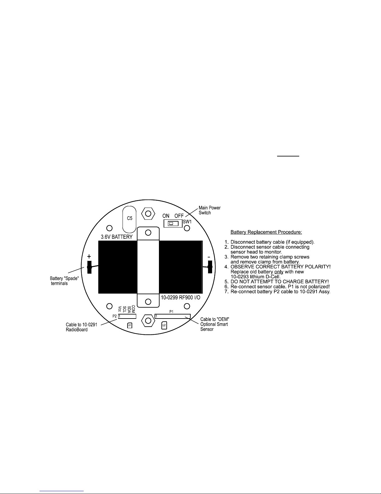
57
OLCT 200 User Manual | 57
Holding the magnet to the UP key for >8 seconds forces a transmission of the current
reading value.
6.4 #10-0299 OLCT 200 Battery I/O PCB with Power Switch
Battery powered wireless OLCT 200 electronics consists of the lower 10-0299/Battery
I/O PCB (Figure 2-3) connected by a cable to the upper Display assembly with 10-0291
RF Module PCB (Figure 2-3). The 10-0293 3.6 volt lithium ‘D’ cell battery will
continuously power the unit for up to one year and may be replaced by following the
procedure in Figure 6-1.
Power switch (SW1), on the 10-0299 Battery PCB, applies battery power to the OLCT
200 monitor. SW1 should be OFF if the monitor is to be out of service for long periods.
IMPORTANT: Do not turn SW1 ON until the controller designated as Server is fully
operational and ready to communicate to the OLCT 200. Battery life is reduced if the
OLCT 200 is on for long periods while unable to communicate to the Server controller.
IMPORTANT: DO NOT ATTEMPT TO CHARGE THIS BATTERY OR REPLACE
WITH ANY OTHER THAN PART # 10-0293 FROM OLDHAM.
Figure 6-1: 10-0299/Battery I/O PCB
6.5 WIRELESS COMMUNICATION SETUP
The Communications menu provides access to RADIO SETUP menus described
below. Hop Channel and System ID settings must match these settings in the Server.
Remote ID must be unique to each OLCT 200. Items tagged with an asterisk affect
power consumption and may have significant affects upon battery life.
Page 58

OLCT 200 User Manual | 58
Figure 6-2: Radio Setup Menu
Hop Channel may be set from 1-32 and assigns the pseudo-random radio
frequency hopping pattern. A transceiver will not go In Range of or
communicate with a transceiver operating on a different Hop Channel.
Different hop channels can be used to prevent radios in one network from
listening to transmissions of another. Installations having more than one
Server network should also have different hop channels for each network.
2.4GHZ variation: Hop channels on 2.4 GHZ models may be set between
0 and 39. Hop channels 0-19 includes EU “low band” frequencies 2406 –
2435MHZ. Hop channels 20-39 includes EU “high band” frequencies
2444 – 2472MHZ.
IMPORTANT!! EXPLORE WHAT FREQUENCIES ARE APPROPRIATE
FOR THE FINAL LOCATION OF ANY WIRELESS SYSTEM.
Remote ID may be set from 1-255 and acts as the “RTU” address for this
particular OLCT 200. Controller channels receiving this monitor’s data must
also be configured with this matching Remote ID address.
System ID may be set from 1-255 and is similar to a password character or
network number and makes network eavesdropping more difficult. A
transceiver will not go In Range of or communicate with a transceiver
operating on a different System ID.
*TX Multiples allows up to 5 consecutive repeats of EVERY transmission.
The default setting of 1 should only be increased if there is no other way to
improve communications success. Power consumption increases with radio
transmissions and battery life will be affected by raising the TX Multiples
setting.
*RF Handshaking affects the way RF transmissions are made by the OLCT
200. This menu may be set for OFF (default) or ON. OFF requires no
acknowledge from the receiving server. ON should be used only when
transmitting to a single receiving server (such as WX4, WX16 or WX64).
Since ON creates an “acknowledge” hand shake returned from the receiver,
only one receiver is allowed to avoid data collisions of the “acknowledge”
signal. If an “acknowledge” is not received by the OLCT 200 it transmits
repeatedly up to 16 times.
RF HANDSHAKING = OFF may be used for any application but is required
when transmitting to a Server and other receiver Client radios (Example is
Page 59

59
OLCT 200 User Manual | 59
with an WX16 Controller as server along with additional Relay Modules,
WX16 and WX4 Clients). RF HANDSHAKING = ON always transmits the
packet 4 times and does not require any “acknowledge” returned by the
receivers.
*TX Power (900MHZ models only) may be set for 10 mW, 200mW, 400mW
and 1 watt. Since some OLCT 200’s are battery powered the TX Power
setting should be as low as possible to sustain reliable communication. The
maximum TX Power setting is 30db (1 watt) and each time TX power is
reduced by half, antenna transmit power is reduced by 3dB.
2.4GHZ variation: The TX Power menu is not available in 2.4GHZ models
and is fixed at 50mW.
TX Verbose is unavailable for firmware revisions 3.09 and earlier.
Wakeup Time menu is new to firmware revision 3.09 and determines how
often the radio is activated WHEN THERE IS NOT AN A1 or A2 LEVEL
ALARM. The default value is 300 seconds (5 minutes) but this may be
reduced to as low as 6 seconds. Intervals are rounded up to the nearest 6
seconds regardless of the menu entry (example: 50 second entry transmits
every 54 seconds).
IMPORTANT: More frequent RF transmissions deplete the battery faster!
Radio Status opens a page indicating if the OLCT 200 is In Range of the
Server. A voltage reading on this page displays the internal 3.3V power
supply value.
TX Multiples, RF Handshaking and TX Power menu settings are available to improve
communications reliability by increasing the quantity and power of wireless
transmissions.
IMPORTANT! Ensure proper selection and location of antennas before increasing TX
Multiples and TX Power settings! Battery life will be reduced by increasing these
settings. Proper selection and location of antennas contributes much more to
successful communications, without sacrificing battery life, than these settings.
6.5.1 OLCT 200 AND WX16 BASE STATIONS
Figure 6-3 shows correct settings for the WX16 base station’s “Data From” menu
to receive data from OLCT 200’s. Each WX16 channel’s Remote ID must match the
OLCT 200’s Remote ID setting (see section 6.7) in order for its VALUE to appear on
the desired WX16 channel. The OLCT 200 counts value equals 75 counts, or -15.6%,
during CAL MODE. Enabling the WX16’s “INPUT MARKER” menu as shown on the
right menu in Figure 6-3 causes the WX16 to indicate IN CAL when the OLCT 200 has
its CAL MODE activated.
Page 60

OLCT 200 User Manual | 60
Input Req set for VALUE means this WX16 channel reads the OLCT 200’s monitored
gas value. If the Input Req menu is set for BATT this WX16 channel reads the battery
voltage from the OLCT 200 with the same Remote ID. To properly display an OLCT
200’s battery voltage the WX16 engineering unit range should be 0-5.00 VDC. Even if
this channel reads VALUE from the OLCT 200, the battery voltage is displayed at the
bottom of this WX16 menu as shown in Figure 6-3.
Figure 6-3: WX16 Base Station “Data From” Menu
6.5.2 OLCT 200 AND WX4 BASE STATIONS
FIGURES 6-4 and 6-5 show correct settings for a WX4 base station to receive
data from OLCT 200’s.
Figure 6-4
WX4 base stations must have their Communications menus set for Wireless Receiver
mode as shown in Figure 6-4. In Receiver mode the WX4 may have 1-4 channels
configured to receive input data from 1-4 OLCT 200 sensor transmitters.
Channel input type is configured in the ANALOG SETUP menu located within the
Input/Output Setup menus as shown in Figure 6-5. OLCT 200’s transmit 200 counts
for 0% and 1000 counts for 100% full scale readings so Input Min/Max menu values
should be 200 & 1000. The Rmt. Xmitter ID menu entry must match the Remote Id
address setting in the OLCT 200 providing data to this WX4 channel. Voltage level of
the 3.6 volt lithium battery in this OLCT 200 is also displayed on this screen. The most
recent A/D Counts value is displayed at bottom of the screen.
Page 61

61
OLCT 200 User Manual | 61
Figure 6-5
Page 62

OLCT 200 User Manual | 62
Page 63

63
OLCT 200 User Manual | 63
SECTION 7 - TECHNICIANS ONLY
MENUS
7.1 Introduction
WARNING! Users of these menus must have a detailed understanding of their
functions. Monitoring of target gases, processing of alarms, 4-20mA output values,
Modbus RS-485 and wireless communications should not be relied upon while editing
these menus! Back-up the current configuration prior to altering any Technical menus
in case Restore is required later (see section 5.3).
The TECHNICIAN ONLY menu group contains items that are factory configured
depending upon the type sensor and input connected to the OLCT 200. They should
not be tampered with after installation. If configured incorrectly, some items will
prevent monitoring of target gases. The Set Sensor Voltage menu for setting the
catalytic bead sensor excitation voltage could destroy the sensor. Access requires a
special key sequence of four consecutive UP keystrokes to prevent accidental
modification of critical items.
Figure 7-1a: Technicians Menu Tree- Wired Models
S E N S OR BA L A N C E
Re a d i n g - 3
Co u n t s 4 9 6
UP / D N t o Ch a n g e .
NE X T t o Ex i t .
S E N S OR VOL T A GE
Vo l t s 2 . 0 4
UP / D N t o Ch a n g e .
NE X T t o Ex i t .
WARNI NG! Hi g h v o l t a g e
ma y d a ma g e s e n s o r
* * * * * WA R N I NG* * * * *
Pr e v i o u s Ca l i b r a t i o n
wi l l b e e r a s e d .
EDI T t o c o n f i r m.
NE X T t o e x i t .
Ga i n = Un i t y
EDIT
EDIT
P GA S E T UP
Ga i n 2 5 . 0 %
Co u n t s 10 11
Re a d i n g 10 0
Up / D n t o Ch a n g e .
Ne x t t o e x i t .
S E L E C T I N P UT
Ca t - B e a d ( 3 - Wi r e )
UP / D OWN t o c h a n g e
E D I T t o s e l e c t
NE X T t o e x i t
SENSOR BALANCE & SENSOR VOLTAGE
menus are only active when input type =
“Cat-Bead” 3-Wire”
S E L E C T E U NI T S
EDIT
% L E L
[ Cu s t o m ]
S e t B a l a n c e
S e t S e n s o r Vo l t a g e
S e t Ga i n t o UNI T Y
P r e A mp Ga i n S e t
I n p u t T y p e
Z ER O Ca l Va l 0
>
>
>
>
>
T EC H N I C AL P A GE 2
Ra w Mi n Cn t s 5 11
Ra w Ma x Cn t s 10 0 0
Ma r k e r A c t i v e Ye s
Ma r k e r T X L E D N O
Ma r k L e v e l 3 . 0 mA
Ma r k As * * ME S S A GE *
T EC H N I C AL P A GE 1
Page 64
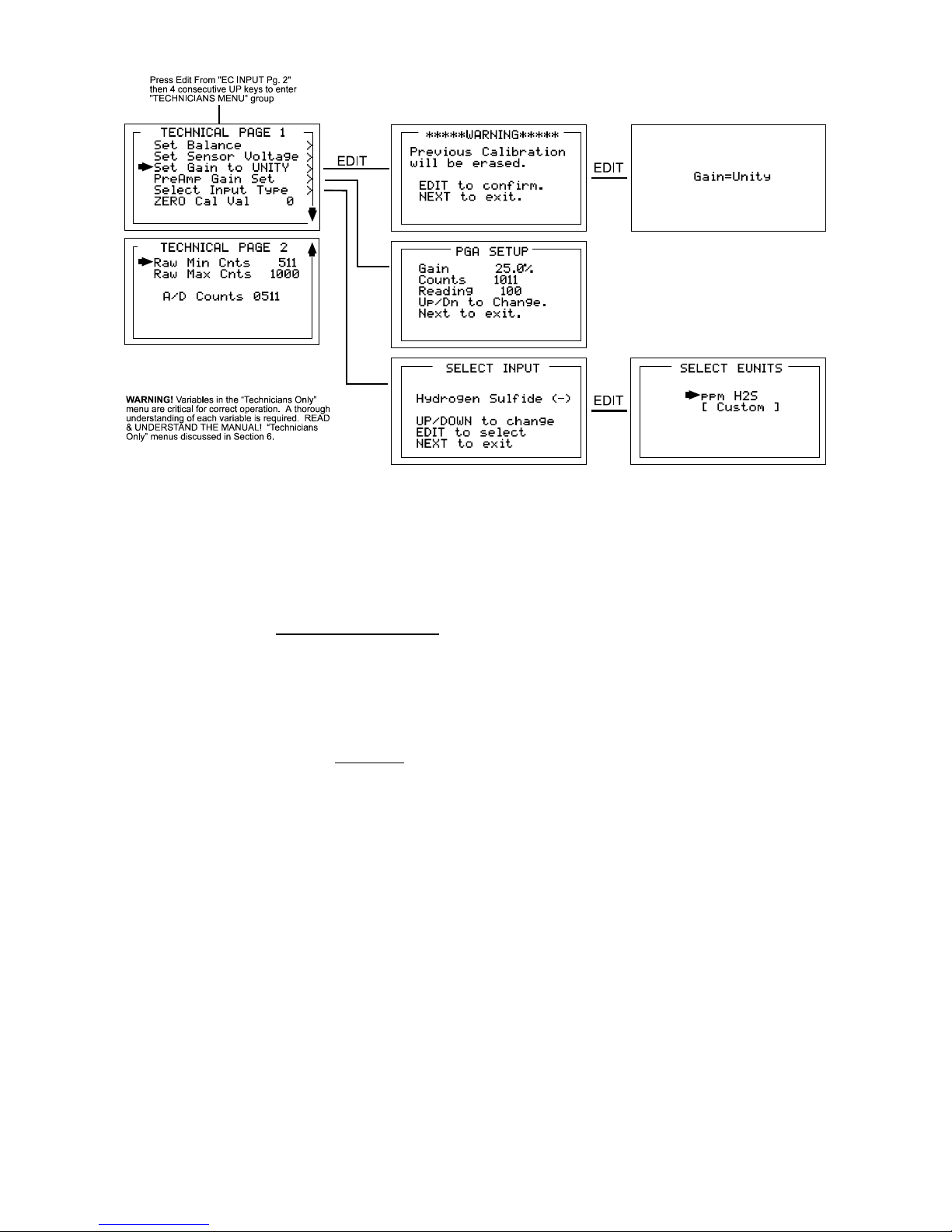
OLCT 200 User Manual | 64
Figure 7-1b: Technicians Menu Tree- Wireless Models
7.2 Set Balance / Set Sensor Voltage (Technicians only!)
Set Balance and Set Sensor Voltage are used when Input Type is for Bridge
sensors. They are factory configured and only require field adjustment if the catalytic
bead sensor is mounted remote from the OLCT 200 or if a new sensor is installed.
Other input type entries draw a line through these menus and they are inactive. OLCT
200 bridge sensors may be from 2 to 6 volts excitation voltage at the sensor. This
means if the sensor is mounted a long distance away the voltage at the OLCT 200 may
have to be higher to compensate for losses in field wiring. Be careful not to exceed
correct sensor volts at the sensor’s A and R terminals.
Set Balance allows balancing of the catalytic bead sensor and must only be performed
with ZERO gas on the sensor (Figure 7-2). Balance is similar to a very coarse ZERO
calibration and does not need to be precise since subsequent calibrations will correct
for small errors. ZERO gas applied to the sensor should provide a Reading of –3 to +3
on the SENSOR BALANCE menu.
Page 65

65
OLCT 200 User Manual | 65
Figure 7-2: Catalytic Bead BALANCE & SENSOR VOLTS Adjust Menus
7.3 Set Gain to Unity (Technicians only!)
Set Gain to UNITY allows resetting previous calibration OFFSET to zero and GAIN to
one. This is the definition of UNITY. A calibration should be performed after setting
UNITY.
Figure 7-3: Set UNITY GAIN Menu
7.4 PreAmp Gain Adjust (Technicians only!)
Depending upon Input Type, OLCT 200 inputs range from a few micro amps to
hundreds of micro amps. PreAmp Gain Set is the adjustment that matches the input
signal range to the OLCT 200 input signal conditioning circuits. Altering the PreAmp
Gain setting automatically resets previous calibration OFFSET & GAIN values to
UNITY as described in section 7.3.
If it is determined the PreAmp Gain value is incorrect, apply the desired up-scale input
and use the UP / DOWN keys to obtain the correct Reading value. Counts are the
10-bit binary A/D value with an active range value of 0 - 1023.
CAUTION: For standard installations, this is a factory adjustment. Do not use the
PreAmp Gain Set menu for calibrating sensors. It should only be adjusted if a new
measurement gas or input range is required.
Figure 7-4: PreAmp Gain Adjust (PGA) Menu
* * * * * WARNI NG* * * * *
Pr e v i o u s Ca l i b r a t i o n
wi l l b e e r a s e d .
E DI T t o c o n f i r m.
NE X T t o e x i t .
Ga i n = Un i t y
EDIT
PGA Se t u p
Ga i n 2 5 . 0 %
Co u n t s 10 11
Re a d i n g 10 0
Up / D n t o C h a n g e .
Ne x t t o e x i t .
Page 66

OLCT 200 User Manual | 66
7.5 Zero Cal Value (Technicians only!)
The Zero Cal Value menu entry allows the zero calibration value to be set for
something other than a zero reading. For example, a OLCT 200 4-20mA input may
represent a BTU Analyzer range of 500 – 1000 BTU’s. In this case, 0% of full scale
equals 500 BTU’s and may be the desired zero calibration point. Other upscale values
may also be used for the zero calibration point by setting this menu item to the desired
engineering unit value. Do not exceed 25% of full scale.
7.6 Raw Min / Max Counts (Technicians only!)
The Raw Min / Max Counts menus determine the range of 10-bit analog to digital
(A/D) converter counts that define 0 & 100% of full scale. Raw Min A/D counts create
0% readings and Raw Max A/D counts create 100% readings. These menus are very
useful in application with non-standard input ranges. For example, for wired models, if
instead of a standard 4-20mA input 8-18mA must be accepted by the OLCT 200. Set
RAW MIN COUNTS to match the 8mA input counts value and RAW MAX COUNTS to
match the 18mA input counts value. The corresponding Zero 0% and Span 100%
readings are entered in the Configuration Menu describe in section 5.3. Live A/D count
values may be viewed from the CAL MODE Information screen described section 4.1.
Page 67
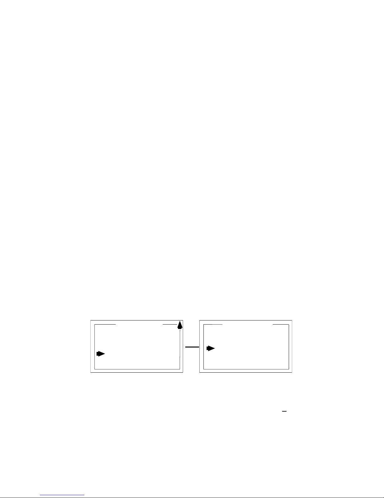
67
OLCT 200 User Manual | 67
SECTION 8 - ARCTIC CONFIGURATIONS
8.1 ARCTIC Option
OLCT 200 3-wire models may be ordered with a special ARCTIC configuration to
include a 175 ohm 4-watt heater / temperature controller circuit mounted to the back of
the 10-0233 Power Supply PCB (Figure 2-5). In addition, when equipped with a locally
mounted 10-0247 Smart Sensor Head (Figure 2-16) ARCTIC Smart sensors are
available with a 1-watt heater / temperature controller for warming the sensor
compartment. This is important since many electrochemical sensors have a low
temperature rating of only -20C. If incoming 10-30VDC power is at least 24VDC, the
ARCTIC option extends OLCT 200 operation down to -55C.
Important! ARCTIC OLCT 200’s consume more power when it is cold! When
temperature inside the OLCT 200 enclosure is below -25C the 175 ohm 10-0233 PCB
heater is connected across the incoming DC power terminals. When an ARCTIC
Smart Sensor is installed, its 1-watt heater is connected across the OLCT 200’s
internal 5VDC power supply when Sensor Temp is below the Setpoint (see section
8.1.1). These additional loads must be considered when sizing the installation’s DC
power supply.
8.1.1 ARCTIC Smart Sensor Temperature Setpoint Option
Both the O2/TOXIC and LEL/Current channels (see section 3.1.1) are capable of
accepting ARCTIC Smart Sensors with 1-watt heater / temperature controller circuits.
ARCTIC sensor temperature controllers have a unique address that is automatically
detected by the OLCT 200. This activates the Sensor Temp menu on page 2 of the
channel’s main menu as shown below in Figure 8-1. Selecting Sensor Temp and
pressing EDIT opens a window displaying the sensor’s current temperature and the 1watt heater’s Setpoint. When the Sensor Temp value is below the Setpoint value the
heater is on. This feature is helpful in applications where the sensor temperature must
be higher than the ambient temperature to function properly.
Figure 8-1: ARCTIC Sensor Temperature Menu
Entering YES in the Marker Active menu also activates Marker TX LED, Mark Level,
and Mark As menus. Mark Level allows entering the <3.75mA value (+.2mA) to
detect. Mark As allows entry of the up to 10 digit ASCII message the LCD readout will
display when the Marker is detected. Marker TX LED menu = YES, causes the front
L E L / MOS T EMP
Se n s o r T e mp 2 8 . 7 5°C
Se t p o i n t - 0 . 0 0°C
L E L I NP UT 2
L C D Co n t r a s t A d j .
Mo d b u s RS 4 8 5 Po r t
Se c u r i t y
T e c h n i c i a n s ONL Y
Se n s o r T e mp
F i r mwa r e Re v .
>
>
>
>
>
EDIT
Page 68

OLCT 200 User Manual | 68
panel TXD LED (see Figure 2-1) to also illuminate when the Marker is detected.
Important: Optional 10-0234 RS-485 modbus port will not function if “Marker TX
LED” menu must = YES.
Page 69

69
OLCT 200 User Manual | 69
SECTION 9 - SENSORS
9.1 Catalytic Bead (LEL) Sensors
Factory Default Settings
Ref #
Gas
Range
Resolution
Cal Gas
Low Alarm
High
Alarm
10
Combustible,
LEL, Methane
Cal
0-100%
LEL
1% LEL
50% LEL
10% LEL
20% LEL
11
Combustible,
LEL, Pentane
Cal
0-100%
LEL
1% LEL
25% LEL
10% LEL
20% LEL
12
Combustible,
LEL, Hydrogen
Cal
0-100%
LEL
1% LEL
25% LEL
10% LEL
20% LEL
9.2 Infrared (IR) Sensors
Factory Default Settings
Ref
#
Gas
Range
Resolution
Cal Gas
Low Alarm
High
Alarm
20
CO2
0-5%
Vol
0.1% Vol
2.5% Vol
0.5% Vol
1.0% Vol
21
Methane, LEL
0-100%
LEL
1% LEL
50% LEL
10% LEL
20% LEL
22
Propane, LEL
0-100%
LEL
1% LEL
25% LEL
10% LEL
20% LEL
26
Ethylene, LEL
0-100%
LEL
1% LEL
50% LEL
10% LEL
20% LEL
Page 70
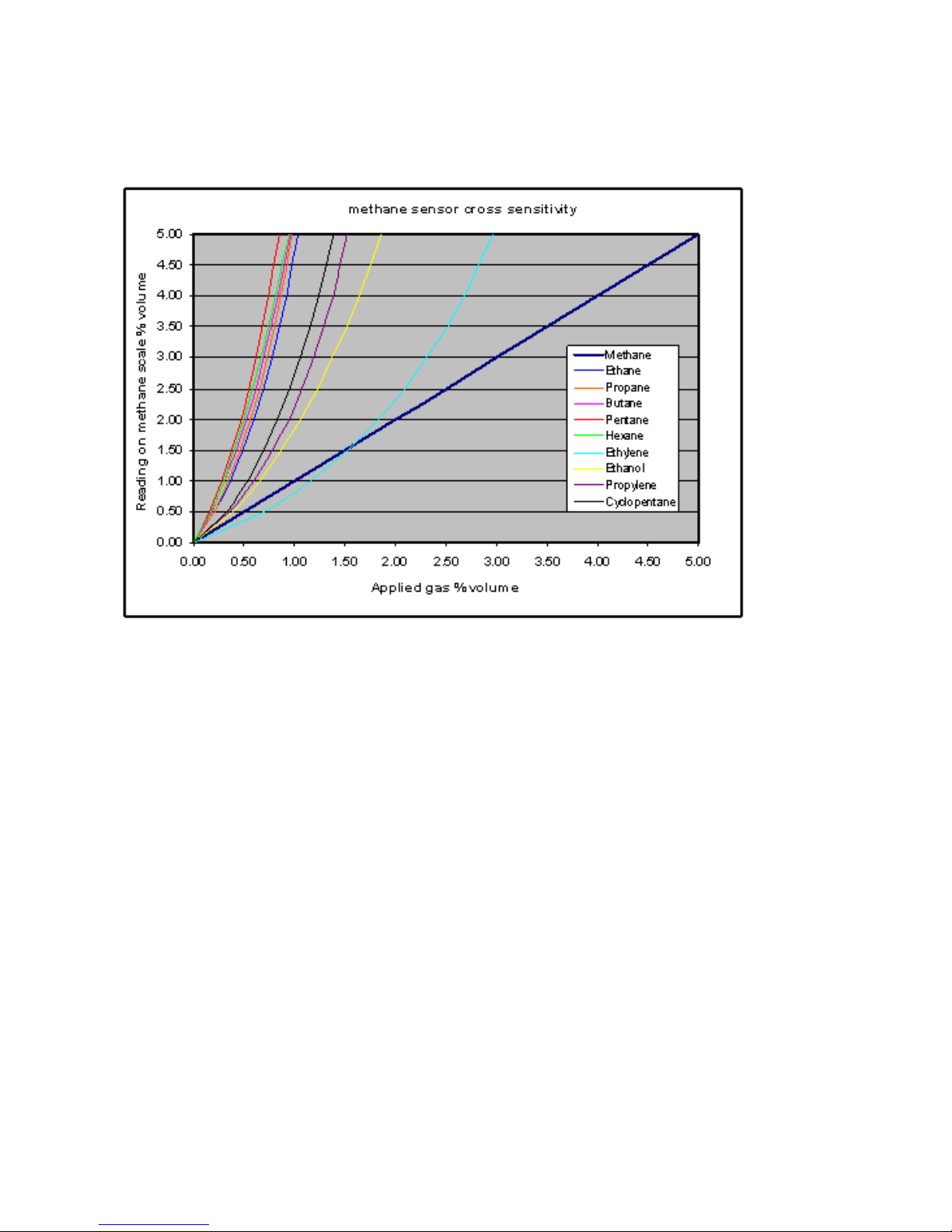
OLCT 200 User Manual | 70
9.2.1 IR-Methane Sensor
The methane IR sensor is only intended to monitor methane gas. As seen in Figure
9.1, the cross-sensitivity of the methane IR sensor does not permit accurate measure
of other combustible gases. It should be noted however, that the Methane-IR sensor
WILL respond to other combustible gases and is not Methane specific.
Figure 9-1 Cross-sensitivity chart for OLCT 200Methane IR Sensor.
The output of the IR sensor can be disrupted by sudden changes in temperature. If
there is an excessive change in the ambient temperature, gas sample temperature or
flow rate, then the output signal will be monmentarily frozen. Correct operation is
restored when the effects of the transient have settled. Rates of change in the ambient
temperature should be restricted to 2C/minute and gas flow rates kept below 0.6
L/minute.
Extreme pressure variations will cause errors in readings. The unit should be
recalibrated if the atmospheric pressure change is greater than 10% from the orignial
pressure.
Do not expose the sensor to corrosive gases such as Hydrogen Sulphide.
Do not allow condenseation to occur inside the sensor.
Page 71
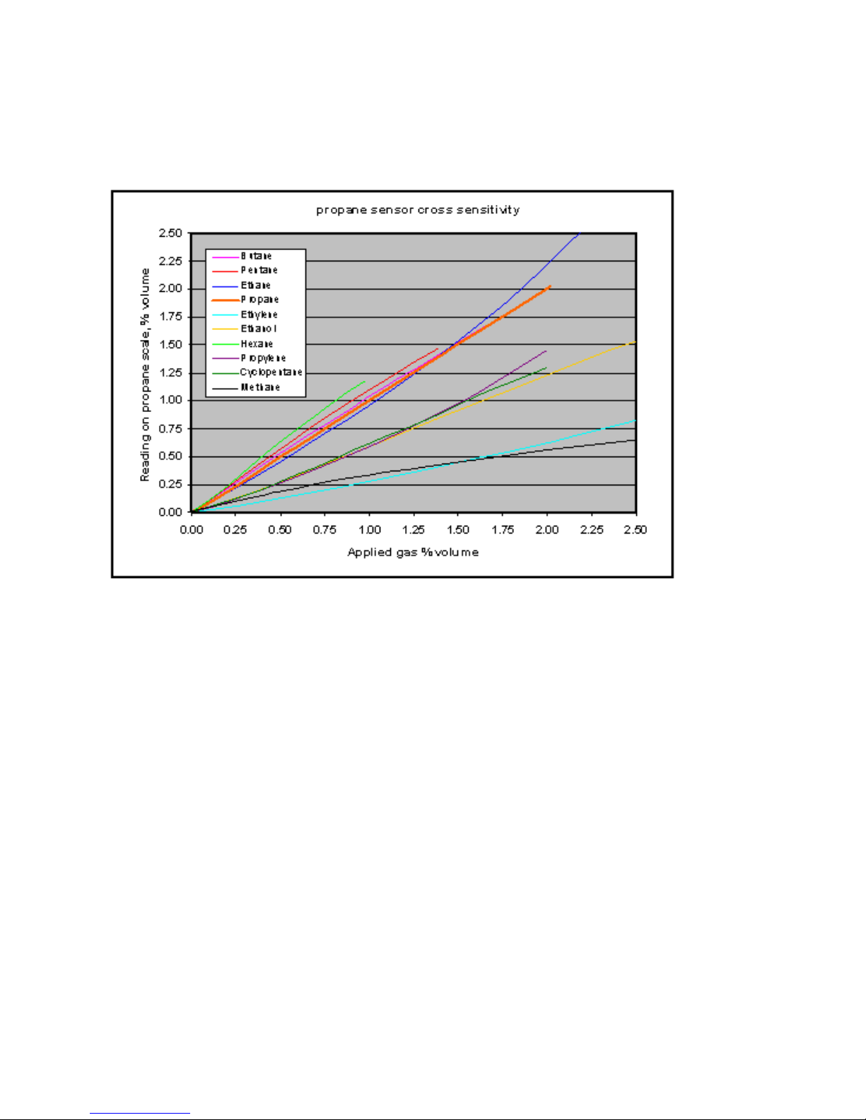
71
OLCT 200 User Manual | 71
9.2.2 IR-Propane Sensor
The propane IR sensor is factory configured to accurately monitor propane gas. As
seen in Figure 9-2, the cross-sensitivity of the propane IR sensor does permit accurate
measure of other combustible gases via a cross-reference factor. It should be noted
however, that the Propane-IR sensor WILL respond to other combustible gases and is
not Propane specific.
Figure 9-2 Cross-sensitivity chart for OLCT 200 Propane IR Sensor.
The output of the IR sensor can be disrupted by sudden changes in temperature. If
there is an excessive change in the ambient temperature, gas sample temperature or
flow rate, then the output signal will be monmentarily frozen. Correct operation is
restored when the effects of the transient have settled. Rates of change in the ambient
temperature should be restricted to 2C/minute and gas flow rates kept below 0.6
L/minute.
Extreme pressure variations will cause errors in readings. The unit should be
recalibrated if the atmospheric pressure change is greater than 10% from the orignial
pressure.
Do not expose the sensor to corrosive gases such as Hydrogen Sulphide.
Do not allow condenseation to occur inside the sensor.
Page 72

OLCT 200 User Manual | 72
9.2.3 IR-CO2 Sensor
The CO2 IR sensor is factory configured to accurately monitor Carbon Dioxide gas.
The output of the IR sensor can be disrupted by sudden changes in temperature. If
there is an excessive change in the ambient temperature, gas sample temperature or
flow rate, then the output signal will be monmentarily frozen. Correct operation is
restored when the effects of the transient have settled. Rates of change in the ambient
temperature should be restricted to 2C/minute and gas flow rates kept below 0.6
L/minute.
Extreme pressure variations will cause errors in readings. The unit should be
recalibrated if the atmospheric pressure change is greater than 10% from the orignial
pressure.
Do not expose the sensor to corrosive gases such as Hydrogen Sulphide.
Do not allow condenseation to occur inside the sensor.
9.2.4 IR-Ethylene Sensor
The Ethylene IR sensor is factory configured to accurately monitor Ethylene gas.
The output of the IR sensor can be disrupted by sudden changes in temperature. If
there is an excessive change in the ambient temperature, gas sample temperature or
flow rate, then the output signal will be monmentarily frozen. Correct operation is
restored when the effects of the transient have settled. Rates of change in the ambient
temperature should be restricted to 2C/minute and gas flow rates kept below 0.6
L/minute.
Extreme pressure variations will cause errors in readings. The unit should be
recalibrated if the atmospheric pressure change is greater than 10% from the orignial
pressure.
Do not expose the sensor to corrosive gases such as Hydrogen Sulphide.
Do not allow condenseation to occur inside the sensor.
9.3 Photoionization Detection (PID) Sensors
Factory Default Settings
Ref
#
Gas
Range
Resolutio
n
Cal Gas
Low Alarm
High
Alarm
30
Volatile
Organic
Compounds
0-500ppm
1 ppm
100 ppm
(Isobutylene)
100 ppm
200 ppm
! Caution ! Note on Silicones:
PIDs are not permanently damaged by Silicones but they can potentially harm the
windows of the lamps and reduce response to some gases. This can usually be
Page 73
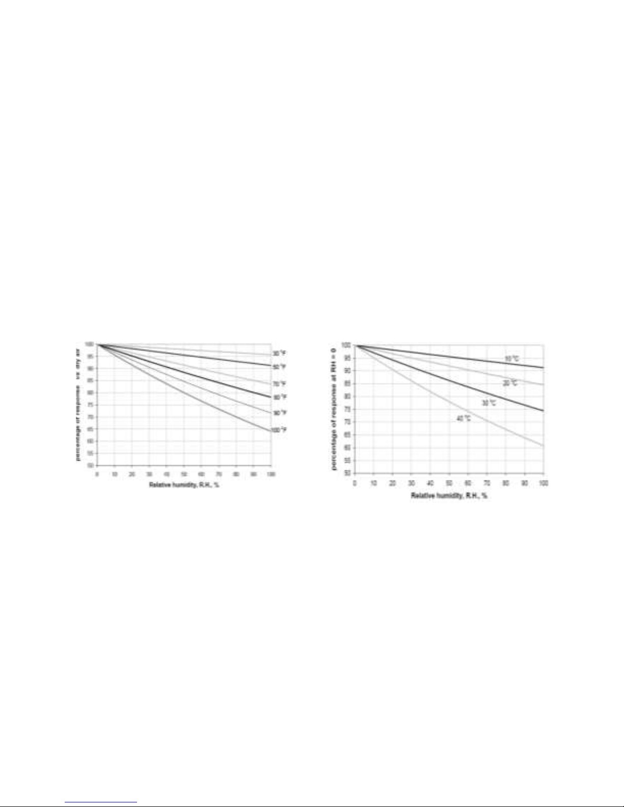
73
OLCT 200 User Manual | 73
addressed by polishing the lamp window with alumina powder. See cleaning kit P/N
78105025
Effect of Temperature
The response of the OLCT200 PID can be significantly affected by temperature. Most
significantly, in environments below 0°C the measurement can be +50% or more of the
actual gas concentration. As a result, it is highly recommended that OLCT200 PID be
calibrated often and when seasonal temperature changes occur.
Effect of Humidity
Water is not itself detected by PID; However, water absorbs a portion of the light that
otherwise promotes a response from a photo-ionizable gas.
The response of the OLCT200 PID to humidity can be seen in the figures presented
below, for Fahrenheit and Celsius temperatures. For example, it can be seen that at
80°F and 90% relative humidity (RH), a response is decreased from that in dry air by
20%. This effect will be the same for any detectable gas.
Maintenance
The electronics in the OLCT200 PID sensor are designed to be maintenance-free and
not accessible. Periodic sensor maintenance is required for the Mini Pellet and the
lamp.
The OLCT200 PID lamp will need occasional cleaning. How often depends on the
environment you are measuring. If you are measuring indoor air quality where the VOC
concentrations are low and there are few particulates, then a monthly or even less
frequent calibration may be adequate. However, if you are measuring high VOC
concentrations and particulates are present in high concentration then check
calibration frequently and when the PID has lost sensitivity or error state shows,
change the stack as explained below.
Page 74

OLCT 200 User Manual | 74
Signs when the PID needs attention:
If the baseline climbs after you zero the PID, then the electrode stack needs
replacing.
If the PID becomes sensitive to humidity, then the electrode stack needs
replacing.
If the baseline shifts/unstable when PID moves, then electrode stack needs
replacing.
If sensitivity has dropped too much (note the change required when checking
calibration), then the lamp needs cleaning.
Lamp Cleaning
Inspection of the lamp may reveal a layer of contamination on the detection window
that presents itself as a 'blue hue.' To check for contamination, hold the lamp in front of
a light source and look across the window surface
Only clean the lamp using the recommended lamp cleaning kit and detailed
instructions. To avoid contaminating the sensor and affecting accuracy, do not touch
the lamp window with bare fingers. You may touch the lamp body with clean fingers.
PID lamp cleaning kit (P/N 78105025)
The vial of cleaning compound contains alumina (CAS Number 1344-28-1) as a very
fine powder. Cleaning should be undertaken in a well-ventilated area. A full material
safety data sheet MSDS is available on request from Ion Science Ltd. Key safety
issues are identified below:
Handling:
• Do not breathe in the powder. Avoid contact with skin,
eyes and clothing
• Wear suitable protective clothing
• Follow industrial hygiene practices: Wash face and
hands thoroughly with soap and water after use and
before eating, drinking, smoking or applying cosmetics.
Hazard identification:
• May cause irritation of respiratory tract and eyes
Storage:
• Keep container closed to prevent water
adsorption and contamination.
Cleaning the Lamp
Use of PID lamp cleaning P/N 78105025
1. Open the container of alumina polishing compound.
2. With a clean cotton bud, collect a small amount of
the powder.
Page 75

75
OLCT 200 User Manual | 75
3. Use this cotton bud to polish the PID lamp window. Use a circular action,
applying light pressure to clean the lamp window. Do not touch the lamp window
with fingers.
4. Continue polishing until an audible “squeaking” is made by the cotton bud
moving over the window surface. (usually within 15 seconds)
5. Remove the residual powder from the lamp window with a clean
cotton bud. Care must be taken not to touch the tips of cotton buds that are to be
used to clean the lamps as this may contaminate them with finger print oil.
6. Ensure the lamp is completely dry and any visible signs of contamination are
removed before refitting.
Replacing Lamp and Electrode Stack
Discarding the PID pellet
Discard the contaminated electrode stack. The electrode stack does not have any toxic
components, but if it has been contaminated by toxic materials, then show due care
when disposing.
Re-fitting PID pellet and lamp
Caution! Never refit a damaged lamp
1. Place the lamp inside the O-ring seal in the
pellet as illustrated. Twist the lamp slightly during
insertion to ensure the lamp window is snug
against the pellet’s front electrode. The lamp
should be freely supported by the O-ring.
2. Lay the pellet front face down on a clean, flat
surface and then screw the lamp down into the
Oring until it firmly abuts against the front electrode
face – this is most important. Then bring the PID body carefully down over the lamp so
as not to disturb its positioning within the pellet and then push the body firmly onto the
pellet face down so that it clicks into place.
3. Refit the sensor into the sensing equipment.
4. Re-calibrate the OLCT200 PID
Replacement Parts
78105024 – Service Kit (Includes electrode stack, 10.6eV bulb, bulb spring, and
extraction tool.)
78105025 – Cleaning Kit (Includes lamp cleaning kit and extraction tool.)
Page 76

OLCT 200 User Manual | 76
9.4 Electrochemical Sensors
Factory Default Settings
Ref
#
Gas
Range
Resolution
Cal
Gas
Low
Alarm
High
Alarm
41
Chlorine (Cl2)
0-50ppm
0.1ppm
10ppm
0.5ppm
1.0ppm
43
Carbon Monoxide (CO)
0-100ppm
1ppm
100ppm
35ppm
70ppm
44
Carbon Monoxide (CO)
0-300ppm
1ppm
100ppm
35ppm
70ppm
48
Hydrogen Sulfide (H2S)
0-30ppm
1ppm
25ppm
10ppm
20ppm
49
Hydrogen Sulfide (H2S)
0-100ppm
1ppm
25ppm
10ppm
20ppm
50
Hydrogen Chloride (HCl)
0-30ppm
0.1ppm
10ppm
5ppm
10ppm
54
Ammonia (NH3)
0-100ppm
1ppm
25ppm
25ppm
50ppm
55
Ammonia (NH3)
0-500ppm
1ppm
50ppm
25ppm
50ppm
60
Nitrogen Dioxide (NO2)
0-30ppm
0.1ppm
5ppm
1.0ppm
2.0ppm
61
Oxygen (O2)
0-30%vol
0.1% Vol
20.9%
19.5%
23.5%
66
Sulfur Dioxide (SO2)
0-30ppm
0.1ppm
5ppm
2.0ppm
4.0ppm
Page 77

77
OLCT 200 User Manual | 77
9.5 Spare Sensors
OLCT 200 Replacement Sensors (without Arctic Heater)
Part Number
Description
78105008-10A
10 = LEL 0-100% (Catalytic Bead) (Methane Cal)
78105008-11A
11 = LEL 0-100% (Catalytic Bead) (Pentane Cal)
78105008-12A
12 = LEL 0-100% (Catalytic Bead) (Hydrogen Cal)
78105007-20A
20 = Carbon Dioxide 0 - 5% Vol (IR)
78105007-21A
21 = Methane 0 -100% LEL (IR)
78105007-22A
22 = Propane 0 -100% LEL (IR)
78105007-26A
26 = Ethylene 0 -100% LEL (IR)
78105006-30A
30 = VOC's (PID)
78105005-41A
41 = Chlorine (Cl2) 0 10.0ppm (EC)
78105005-43A
43 = Carbon Monoxide(CO) 0 - 100ppm (EC)
78105005-44A
44 = Carbon Monoxide (CO) 0 - 300ppm (EC)
78105005-48A
48 = Hydrogen Sulfide (H2S) 0 - 30.0ppm (EC)
78105005-49A
49 = Hydrogen Sulfide (H2S) 0 - 100ppm (EC)
78105005-50A
50 = Hydrogen Chloride (HCl) 0 - 30ppm (EC)
78105005-54A
54 = Ammonia (NH3) 0 - 100ppm (EC)
78105005-55A
55 = Ammonia (NH3) 0 - 500ppm (EC)
78105005-60A
60 = Nitrogen Dioxide (NO2) (0 - 30.0ppm) (EC)
78105005-61A
61 = Oxygen (O2) 0 - 30% Vol (EC)
78105005-66A
66 = Sulfur Dioxide (SO2) 0 -30.0ppm (EC)
Page 78

OLCT 200 User Manual | 78
OLCT 200 Replacement Sensors (with Arctic Heater)
Part Number
Description
78105007-20B
20 = Carbon Dioxide 0 - 5% Vol (IR)
78105007-21B
21 = Methane 0 -100% LEL (IR)
78105007-22B
22 = Propane 0 -100% LEL (IR)
78105007-26B
26 = Ethylene 0 -100% LEL (IR)
78105006-30B
30 = VOC's (PID)
78105005-41B
41 = Chlorine (Cl2) 0 10.0ppm (EC)
78105005-43B
43 = Carbon Monoxide(CO) 0 - 100ppm (EC)
78105005-44B
44 = Carbon Monoxide (CO) 0 - 300ppm (EC)
78105005-48B
48 = Hydrogen Sulfide (H2S) 0 - 30.0ppm (EC)
78105005-49B
49 = Hydrogen Sulfide (H2S) 0 - 100ppm (EC)
78105005-50B
50 = Hydrogen Chloride (HCl) 0 - 30ppm (EC)
78105005-54B
54 = Ammonia (NH3) 0 - 100ppm (EC)
78105005-55B
55 = Ammonia (NH3) 0 – 500ppm (EC)
78105005-60B
60 = Nitrogen Dioxide (NO2) (0 - 30.0ppm) (EC)
78105005-61B
61 = Oxygen (O2) 0 - 30% Vol (EC)
78105005-66B
66 = Sulfur Dioxide (SO2) 0 -30.0ppm (EC)
Page 79

79
OLCT 200 User Manual | 79
Page 80

The Fixed Gas Detection Experts
EUROPEAN PLANT AND OFFICES
Z.I. Est – rue Orfila CS 20417 – 62027 Arras Cedex FRANCE
Tél: +33 (0)3 21 60 80 80 – Fax: +33 (0)3 21 60 80 00
Website: http://www.oldhamgas.com
AMERICAS
Tel: +1-713-559-9280
Fax: +1-281-292-2860
americas@oldhamgas.com
ASIA PACIFIC
Tel: +86-21-3127-6373
Fax: +86-21-3127-6365
sales@oldhamgas.com
EUROPE
Tel: +33-321-608-080
Fax: +33-321-608-000
info@oldhamgas.com
 Loading...