

Page 1
1
User manual
OLCT 20
Part Number: NPO20GB
Revision: E.0
The Fixed Gas Detection Experts
Page 2

2
Copyright April 2018 by Oldham S.A.S
All rights reserved. No reproduction of all or part of this document, in any for mis
permitted without the written consent of Oldham S.A.S.
All information provided in this document is accurate to the best of our
knowledge.
As a result of continuous research and development, the specifications of this
product may be changed without prior notice.
Oldham S.A.S
Rue Orfila
Z.I. Est – CS 20417
F – 62027 ARRAS Cedex
Tel: +33 (0)3 21 60 80 80
Fax: +33 (0)3 21 60 80 00
Page 3

Table of Contents
iii
Table of Contents
| Overview.............................................................. 1
Limitation of Liability .........................................................................................1
Ownership clauses ...........................................................................................1
Warnings ...........................................................................................................1
Warranty ...........................................................................................................2
Important Information ........................................................................................2
Destruction of equipment ..................................................................................2
Symbols used ...................................................................................................3
| Description .......................................................... 5
Overview ...........................................................................................................5
Main characteristics of the various versions .....................................................5
Mechanical installation of the various versions ................................................6
| Wiring Arrangements ......................................... 7
3-wire version (OLC 20d, OLCT 20d) ...............................................................7
2-wire version (OLCT 20d) ...............................................................................7
2-wire Intrinsic Safety version (OLCT 20i) ........................................................8
| Installation ........................................................... 9
Regulations and operating conditions ..............................................................9
Equipment required ..........................................................................................9
Positioning the detector ....................................................................................9
Mounting the detector .................................................................................... 10
| Maintenance ...................................................... 11
Maintenance frequency ................................................................................. 11
Detector OLC 20 ............................................................................................ 12
Transmitters OLCT 20 ................................................................................... 12
Replacing a sensor on OLCT 20 ................................................................... 14
| Spare Parts ........................................................ 15
Flameproof approved replacement sensors .................................................. 15
Intrinsically-safe approved replacement sensors .......................................... 16
| Accessories ...................................................... 17
| Technical Specifications .................................. 19
Common ........................................................................................................ 19
OLC 20d ........................................................................................................ 19
OLCT 20d ...................................................................................................... 19
OLCT 20i ....................................................................................................... 19
Sensors .......................................................................................................... 20
Cross gas factors for combustible gases ....................................................... 21
Page 4

Table of Contents
iv
| EU Declaration of Conformity .......................... 25
| Special instructions for use in explosive
atmospheres and fonctional safety.......................................... 27
General comments ........................................................................................ 27
Warnings ........................................................................................................ 27
Requirements for use in dust explosive atmospheres ................................... 27
Cable entries .................................................................................................. 27
Threaded joints .............................................................................................. 28
Limitations of use ........................................................................................... 28
Transfer curve for OLCT20 gas detectors ..................................................... 29
Marking .......................................................................................................... 29
Page 5

1 – Overwiew 1
| Overview
Thank you for choosing this OLDHAM instrument.
All necessary actions have been taken to ensure your complete satisfaction
with this equipment.
It is important that you read this entire manual carefully and thoroughly.
Limitation of Liability
■ OLDHAM shall not be held responsible for any damage to the equipment or for any
physical injury or death resulting in whole or in part from the inappropriate use or
installation of the equipment, non-compliance with any and all instructions, warnings,
standards and/or regulations in force.
■ No business, person or legal entity may assume responsibility on behalf of OLDHAM,
even though they may be involved in the sale of OLDHAM products.
■ OLDHAM shall not be responsible for any direct or indirect damage, or any direct or
indirect consequence, resulting from the sale and use of any of its products UNLESS
SUCH PRODUCTS HAVE BEEN SELECTED BY OLDHAM ACCORDING TO THE
APPLICATION.
Ownership clauses
■ The drawings, specifications, and information herein contain confidential information
that is the property of OLDHAM.
■ This information shall not, either in whole or in part, by physical, electronic, or any
other means whatsoever, be reproduced, copied, divulged, translated, or used as the
basis for the manufacture or sale of OLDHAM equipment, or for any other reason
without the prior written consent of OLDHAM.
Warnings
■ This is not a contractual document. OLDHAM reserves the right to alter the technical
features of its equipment at any time and for any reason without prior notice.
■ READ THESE INSTRUCTIONS CAREFULLY BEFORE USING FOR THE FIRST
TIME: these instructions should be read by all persons who have or will have
responsibility for the use, maintenance, or repair of the instrument.
■ This instrument shall only be deemed to be in conformance with the published
performance if used, maintained, and repaired in accordance with the instructions of
OLDHAM, by OLDHAM personnel, or by personnel authorized by OLDHAM.
Page 6

1 – Overwiew 2
Warranty
Under normal conditions of use and on return to the factory, parts and workmanship are
guaranteed for 2 years, excluding consumables such as sensors, filters, etc.
Important Information
The modification of the material and the use of parts of an unspecified origin
shall entail the cancellation of any form of warranty.
The use of the unit has been projected for the applications specified in the
technical characteristics. Exceeding the indicated values cannot in any case
be authorized.
Catalytic sensors are susceptible to poisoning by traces of several
substances. This leads to an inhibition which can be permanent or temporary
depending on the contaminant, the concentration of the contaminant, the
duration of exposure to the contaminant.
Poisoning may result from exposure to substances as:
• silicones (e.g. waterproofing, adhesives, release agents, special oils
and greases, certain medical products, commercial cleaning agents)
• tetraethyl lead (e.g. leaded petrol, particularly aviation petrol ‘Avgas’)
• sulfur compounds (sulfur dioxide, hydrogen sulfide)
• halogenated compounds (R134a, HFO, etc.)
• organo-phosphorus compounds (e.g. herbicides, insectic ides, and
phosphate esters in fireproof hydraulic fluids)
Oldham recommends regular testing of fixed gas detection installations (read
0).
Destruction of equipment
European Union only. This symbol indicates that, in conformity with
directive DEEE (2002/96/CE) and in accordance with local regulations,
this product must not be discarded with household waste.
It must be disposed of in a collection area that is designated for this
purpose, for example at a site that is officially designated for recycling of
electrical and electronic equipment (EEE) or a point of exchange for
authorized products in the event of the acquisition of a new product of the
same type.
The OLCT80 transmitter contains a lithium ion battery intended to supply
power to certain parts of the electronic circuit. The battery will be removed
prior to the destruction of the transmitter and deposited in a collection
center for used batteries.
Page 7
1 – Overwiew 3
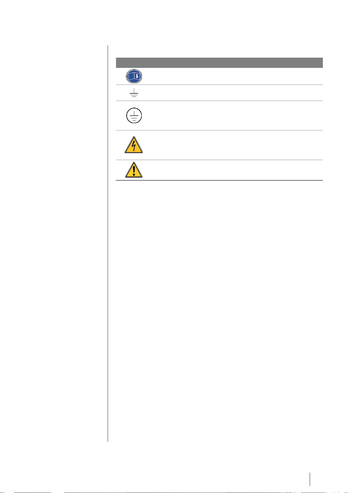
Symbols used
Icon
Signification
This symbol indicates:
useful additional information.
This symbol indicates:
This equipment must be connected to ground.
This symbol denotes:
Protective earth terminal. A cable of the adequate diameter
must be connected to ground and to the terminal having this
symbol
This symbol denotes:
Attention! In the present mode of use, failure to adhere to
the instructions preceded by this symbol can result in a
risk of electric shock and/or death.
This symbol indicates:
You must refer to the instructions.
Page 8

1 – Overwiew 4
Page 9

2 – Description 5
| Description
Overview
OLC 20 gas detectors are catalytic type detectors intended for the detection of
combustible gases. They are flameproof certified (OLC 20d).
OLCT 20 gas detectors are 4-20 mA transmitters and are intended for the
measurement of combustible and toxic gases and oxygen. They are either
flameproof certified (OLCT 20d) or intrinsically safe certified (OLCT 20i).
OLC 20s and OLCT 20s are available in ¾ NPT or M25 screw fittings and are
designed to be attached on a junction box or any compatible generic
transmitters.
Main characteristics of the various versions
OLC 20
OLCT 20
LEL
LEL
TOX/O2
Flameproof design
Intrinsic safety design
3-wire cable / Wheatstone bridge
3-wire cable / 4-20 mA output
2-wire cable / 4-20 mA output
Catalytic sensor
Electrochemical sensor
Replacement catalytic sensor
Replacement pre-calibrated
sensor
Page 10
2 – Description 6
Mechanical installation of the various versions
Please ensure you read the paragraph: Special Specifications for use in
Potentially Explosive Atmospheres in Accordance with European Directive
ATEX 2014/34/EU.
See Appendix 1 for general installation instructions.
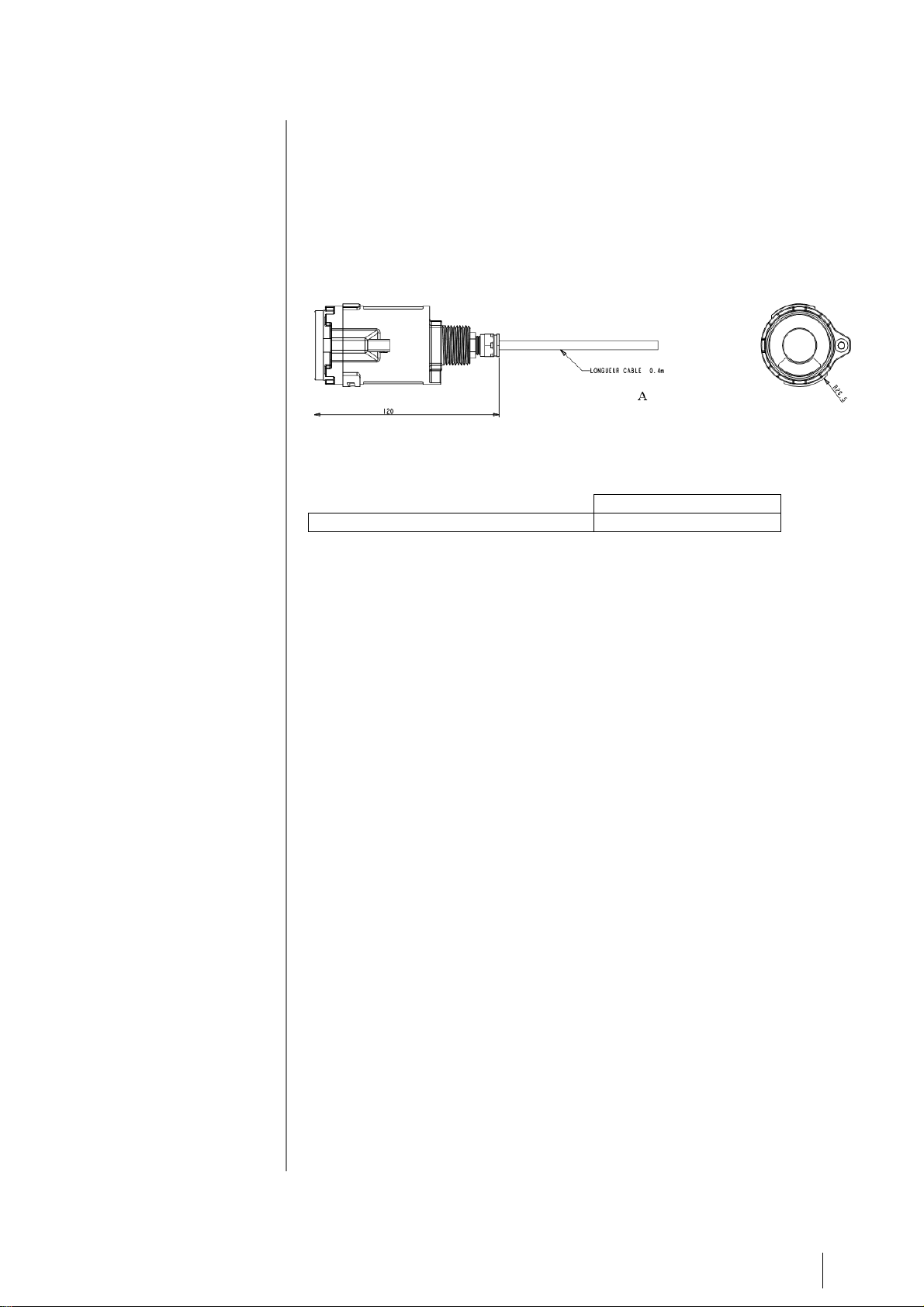
Figure 1 : Dimensions
A Dimensions OLC/OLCT 20
Cable length 0.2 m
Page 11
5 – Maintenance 7
| Wiring Arrangements
Please ensure you read the paragraph: Special Specifications for use in
Explosive Atmospheres in Accordance with European Directive ATEX
2014/34/EU.
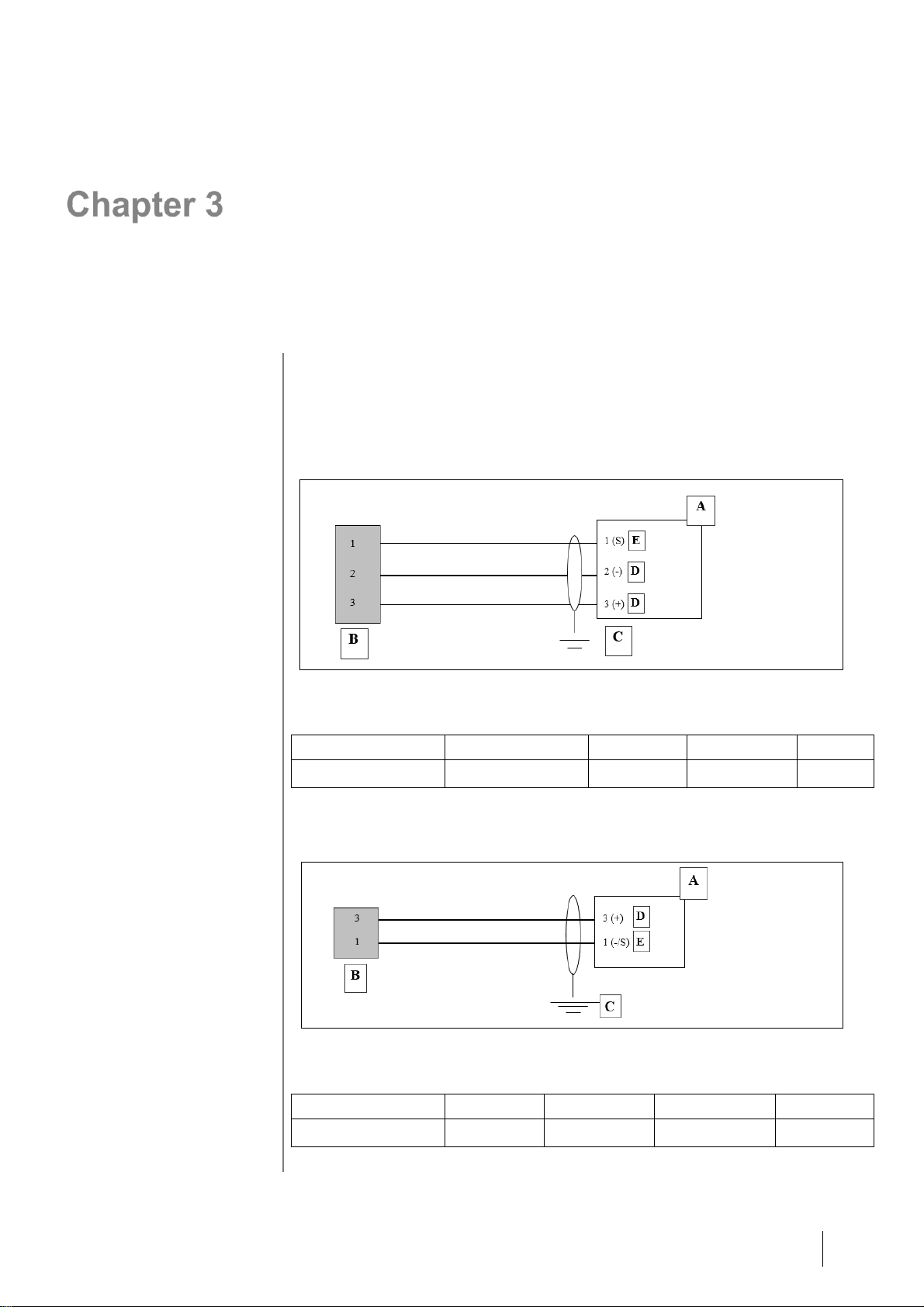
3-wire version (OLC 20d, OLCT 20d)
Figure 2
A
B
C D E
OLDHAM controller
OLC or OLCT 20
Grounding
Power supply
Signal (I)
2-wire version (OLCT 20d)
Figure 3
A
B C D
E
OLDHAM controller
OLCT 20
Grounding
Power supply
Signal (I)
Page 12

5 – Maintenance 8
2-wire Intrinsic Safety version (OLCT 20i)
Figure 4
A
B
C
OLDHAM controller
OLCT 20
Zener Barrier
Page 13

5 – Maintenance 9
| Installation
It is recommended that you read the relevant guides for installing,
operating and maintaining flammable gas and oxygen detectors
(EN 60079-29-2) and toxic detectors (EN 45544-4).
Regulations and operating conditions
■ Installation must comply with current edition of EN 60079-14 for systems
installed in explosive atmospheres and eventually with any local or national
additional requirements that may apply in the country of installation.
■ In general, the ambient temperature, the power supply voltage and power
mentioned in this document pertain to safety precautions against explosion.
These temperatures are not the detector's operating temperatures.
■ OLC20d and OLCT20d are authorized for use in zones 1, 2, 21 and 22 for
ambient temperatures ranging between -20°C to +70°C (except OLC20d HT.
See Chapter 10).
■ OLCT20i are authorized for use in zones 0, 1, 2, 20, 21 and 22 for ambient
temperatures ranging between -20°C to +70°C.
■ The detection sensor must always be in contact with the ambient air.
Therefore:
- Do not cover the detection module.
- Do not apply paint on the detection module.
- Keep dust from building up.
Equipment required
■ Complete detector.
■ Connection cable.
■ Tools for mounting the device.
■ Mounting materials.
Positioning the detector
The detector should be positioned at ground level, on the ceiling, at the height
of the respiratory tract or near air extraction ducts, depending on the application
or the density of the gas to be detected. Heavy gases should be detected at
ground level, while light gases should be detected at ceiling height.
Page 14

5 – Maintenance
10
Mounting the detector
The detector must be installed with the detection sensor pointing downwards.
For combustible gas detectors, tilting the device more than 45° past vertical can
lead to imprecise readings.
Despite its high degree of protection (IP66), it may be necessary to protect the
detector against adverse weather conditions (rain, dust, direct sunlight, etc.) and
from direct spraying with cleaning or maintenance products (causing soiling of
the detection sensor).
The detector must also be positioned so as to allow access to the measuring
sensor so that it can be replaced easily.
Factors to be considered in determining optimal detector positioning:
potential sources of gas and vapour emissions
chemical and physical data on gases and vapours which may be present
liquids with low volatility (place the detectors as near as possible to the leak)
type and concentration of gas leaks (high-pressure jet, slow leak, etc.)
air movements:
- indoors: natural and mechanical ventilation
- outdoors: wind speed and direction
effect of temperature
installation so as to avoid mechanical damage or deterioration caused by
water in summer
positioning to allow easy maintenance, if possible
avoiding direct sunlight on the readout area as this would lead to
maintenance problems
Page 15

5 – Maintenance
11
| Maintenance
The operations explained in this section must be performed by
authorized, qualified personnel because they could affect detection
reliability. Inspection and maintenance must be carried out in
accordance with the current editions of EN60079-17 and eventually
with any local or national additional requirements that may apply in
the country of installation.
It is prohibited to open the transmitter when energized
Periodic inspections ensure that the equipment and system is functioning
properly and providing reliable detection services. The section describes the
preventative maintenance procedures required and how often they are to be
performed. Inspection and maintenance must be carried out in accordance with
the current editions of EN60079-17 and eventually with any local or national
additional requirements that may apply in the country of installation.
Maintenance frequency
Gas detectors are safety devices. Oldham recommends regular testing of fixed
gas detection installations. This type of test involves injecting a standard gas of
sufficient concentration into the detector to trigger pre-set alarms. This test does
not, in any event, replace a full calibration of the detector.
Frequency of gas testing depends on the industrial application in which the
detector is used. Inspection should occur frequently during the months following
installation start-up; later it may be spaced out if no significant problem is
observed. If a detector does not react upon contact with gas, it must be
calibrated. Calibration frequency will depend on the results of these tests
(moisture, temperature, dust, etc.); however, the device should be calibrated at
least once per year.
The site manager is responsible for implementing the safety procedures at the
site. Oldham is not responsible for implementing safety procedures.
Page 16

5 – Maintenance
12
Detector OLC 20
Calibration
Replacing a sensor on an OLC 20
When?
- When the sensor is damaged or cannot be calibrated
- On a preventive basis
How?
- Turn off the relevant measuring channel
- Remove the sensor to be replaced
- Replace it with a new sensor
- Turn on the channel and check that it operates correctly
Transmitters OLCT 20
OLCT 20 gas transmitters are equipped with a pre-calibrated sensor and do not
require any adjustment on installation.
However, as gas detectors are safety equipment, it is recommended to bump
test the complete transmitter after a sensor replacement.
Calibration
After removing the sensor from the transmitter, perform the calibration by using
the calibrating bench provided for that purpose (see CALIBRO’s user manual).
Page 17

5 – Maintenance
13
Procedure
On the controller
On the detector
Set the measuring channel to the
calibration position (alarm relays
inhibited)
Set the measuring channel back
to the "normal" position and
make sure that it is working
properly.
Rotate the
sensor module
and extract it
1
2
Once calibrated put the sensor back in
place or use a replacement sensor and
reinstall the whole assembly.
Loosen the
locking
screw
Page 18

5 – Maintenance
14
Calibration specifications
Calibration shall be performed outside classified areas and by
using suitable equipment that is described during the training
course provided by OLDHAM or by a person authorized by
OLDHAM.
Replacing a sensor on OLCT 20
When?
- When the sensor is damaged or cannot be calibrated.
- On a preventive basis.
How?
- Turn off the relevant measuring channel.
- Remove the sensor to be replaced.
- Replace it with a new, precalibrated unit.
- Turn the channel on and check that it operates correctly.
Page 19

6 – Spare Parts
15
| Spare Parts
All replacement parts must be Oldham-manufactured parts.
The use of non-Oldham parts could jeopardize the
instrument's safety.
Flameproof approved replacement sensors
Part number
Description
6 313 757
OLC 20d sensor cell, 0-100% LEL, VQ1 type
6 313 758
OLC 20d sensor cell, 0-100% LEL, 4F type
6 313 995
OLC20d sensor cell, 0--100% LEL, butadiene/acetylene, VQ1 type
6 313 759
OLC20d sensor cell, 0-100% vol. CH4
6 314 204
OLC 20d sensor cell, 0-100% vol. H2
6 313 988
OLC 20d sensor cell, 0-100% vol. SF6
6 313 689
OLC 20d HT sensor cell, 0-100% LEL, VQ1 type
6 313 685
OLCT 20d sensor cell, 0-100% LEL, VQ1 type
6 313 974
OLCT 20d poison control sensor cell, 0-100% LEL, 4F type
6 313 872
OLCT 20d sensor cell, 0-100% LEL, butadiene/acetylene, VQ1 type
6 313 687
OLCT 20d sensor cell, 0-100% vol. CH4
6 313 986
OLCT 20d sensor cell, 0-100% vol. SF6
6 313 203
OLCT 20d sensor cell, 0-100% vol. H2
6 314 100
Infrared sensor cell, 0-5% vol. CO2, for OLCT 20 XP IR
6 314 101
Infrared sensor cell, 0-10% vol. CO2, for OLCT 20 XP IR
6 314 146
Infrared sensor cell, 0-100% vol. CO2, for OLCT 20 XP IR
6 313 710
OLCT 20d O2 sensor cell, 0-30% vol.
6 313 707
OLCT 20d NH3 sensor cell, 0-100 ppm
6 313 708
OLCT 20d NH3 sensor cell, 0-1000 ppm
6 313 894
OLCT 20d NH3 sensor cell, 0-5000 ppm
6 313 690
OLCT 20d CO sensor cell, 0-100 ppm
6 313 691
OLCT 20d CO sensor cell, 0-300 ppm
6 313 692
OLCT 20d CO sensor cell, 0-1000 ppm
6 313 693
OLCT 20d CO (H2 null) sensor cell, 0-1000 ppm
6 313 695
OLCT 20d H2S sensor cell, 0-30 ppm
6 313 965
OLCT 20d H2S sensor cell, 0-30 ppm, no HC interference
6 313 696
OLCT 20d H2S sensor cell, 0-100 ppm
6 313 697
OLCT 20d H2S sensor cell, 0-1000 ppm
6 313 698
OLCT 20d sensor cell, 0-100 ppm NO
6 313 699
OLCT 20d sensor cell, 0-300 ppm NO
6 313 700
OLCT 20d sensor cell, 0-1000 ppm NO
6 313 706
OLCT 20d sensor cell, 0-2000 ppm H2
6 313 772
OLCT 20d sensor cell, methylene/methylene chloride
Page 20

6 – Spare Parts
16
Part number
Description
6 313 773
OLCT 20d sensor cell, R12
6 313 774
OLCT 20d sensor cell, R134a
6 313 775
OLCT 20d sensor cell, MOS
Intrinsically-safe approved replacement sensors
Part number
Description
6 313 748
OLCT 20i O2 sensor cell, 0 - 30% vol.
6 313 728
OLCT 20i NH3 sensor cell, 0-100 ppm
6 313 729
OLCT 20i NH3 sensor cell, 0-1000 ppm
6 313 895
OLCT 20i NH3 sensor cell, 0-5000 ppm
6 313 694
OLCT 20i CO (H2 null) sensor cell, 0-1000 ppm
6 313 711
OLCT 20i CO sensor cell, 0-100 ppm
6 313 712
OLCT 20i CO sensor cell, 0-300 ppm
6 313 713
OLCT 20i CO sensor cell, 0-1000 ppm
6 313 716
OLCT 20i H2S sensor cell, 0-30 ppm
6 313 717
OLCT 20i H2S sensor cell, 0-100 ppm
6 313 718
OLCT 20i H2S sensor cell, 0-1000 ppm
6 313 719
OLCT 20i NO sensor cell, 0-100 ppm
6 313 720
OLCT 20i NO sensor cell, 0-300 ppm
6 313 721
OLCT 20i NO sensor cell, 0-1000 ppm
6 313 722
OLCT 20i NO2 sensor cell, 0-10 ppm
6 313 723
OLCT 20i NO2 sensor cell, 0-30 ppm
6 313 727
OLCT 20i H2 sensor cell, 0-2000 ppm
6 313 730
OLCT 20i HCl sensor cell, 0-30 ppm
6 313 731
OLCT 20i HCl sensor cell, 0-100 ppm
6 313 724
OLCT 20i SO2 sensor cell, 0-10 ppm
6 313 725
OLCT 20i SO2 sensor cell, 0-30 ppm
6 313 726
OLCT 20i SO2 sensor cell, 0-100 ppm
6 313 734
OLCT 20i Cl2 sensor cell, 0-10 ppm
6 313 746
OLCT 20i ETO sensor cell, 0-50 ppm
6 313 732
OLCT 20i HCN sensor cell, 0-10 ppm
6 313 733
OLCT 20i HCN sensor cell, 0-30 ppm
6 313 736
OLCT 20i COCl2 sensor cell, 0-1 ppm
6 313 740
OLCT 20i CIO2 sensor cell, 0-3 ppm
6 313 735
OLCT 20i O3 sensor cell, 0-1 ppm
6 313 737
OLCT 20i PH3 sensor cell, 0-1 ppm
6 313 739
OLCT 20i HF sensor cell, 0-10 ppm
6 313 738
OLCT 20i AsH3 sensor cell, 0-1 ppm
6 313 747
OLCT 20i SiH4 sensor cell, 0-50 ppm
Page 21

7 – Accessories
17
| Accessories
Accessory
Use
Illustration
Code
Tool kit
Tool kit for maintenance.
6147869
Gas injection
pipe
Inject the calibration gas onto
the measurement sensor.
Impact on reading:
measurement similar to
measurement in diffusion mode.
Impact on response time: none.
6331141
Plastic
material. Risk of
electrostatic
charges. Wipe
with a damp cloth
Gas flow head
Used to take bypass readings.
Impact on reading: none if
calibration is performed under
the same conditions (pipe, flow
rate).
Impact on response time: none.
6327910
Plastic
material. Risk of
electrostatic
charges. Wipe
with a damp cloth
Splash guard
Protects the detector from
liquids.
Impact on reading: none.
Impact on response time:
response time in diffusion mode
may increase for certain gases;
contact us for more information.
6329004
Plastic
material. Risk of
electrostatic
charges. Wipe
with a damp cloth
Splash guard in
Stainless Steel
Protects the detector from
liquids.
Impact on reading: none.
Impact on response time:
response time in diffusion mode
may increase for certain gases;
contact us for more information.
6129010
Splash guard
(high risk)
Protects the detector from
liquids.
Impact on reading: none.
Impact on response time:
response time may increase for
certain gases; contact us for
more information.
6329014
Plastic
material. Risk of
electrostatic
charges. Wipe
with a damp cloth
Remote gas
injection head
Used to detect ambient gases
while a calibration gas injection
pipe is being used. Only for
combustible gases,
Impact on reading: none.
Impact on response time:
negligible.
6327911
Plastic
material. Risk of
electrostatic
charges. Wipe
with a damp cloth
Removable
PTFE protection
filter
Protects the gas inlet from
liquids and dust.
Impact on reading: none, but
this part cannot be used for the
detection of O3, HCL, HF and
Cl2.
Impact on response time:
response time may increase for
certain gases; contact us for
more information.
6335975
Plastic
material. Risk of
electrostatic
charges. Wipe
with a damp cloth
Page 22

7 – Accessories
18
Page 23

8 – Technical Specifications
19
| Technical Specifications
Common
Ingress Protection IP66
Weight 800 g
Dimensions 60 X 120 mm
Source mode current 4-20 mA
Max. current 25 mA
Fault current <1 mA
OLC 20d
Power supply: voltage on detector terminals = 2.8 V max
Power consumption: 3-wire version = 400 mA max
Measurement signal: Wheatstone bridge
Line length (shielded cable): 3-wire version = 1 km with 3x1.5 mm2 (32 ohms
in loop mode)
Output signal mV bridge output, 3 wires
OLCT 20d
Power supply: voltage on detector terminals = 15 Vdc to 30 Vdc
Power consumption: 3-wire version = 100 mA
2-wire version = 25 mA
Load resistance: maximum resistance = 250 ohms
Line length (shielded cable): 3-wire version = 1 km as 3x 1.5 mm2 (32 ohms in
loop mode)
2-wire version = 4 km as 3x 1.5 mm2 (32 ohms in
loop mode)
OLCT 20i
Zener barrier: 28 Vdc max - 300 ohms
Supply voltage for barrier: 19 Vdc to 26 Vdc
Voltage on detector terminals: 10 Vdc to 26 Vdc
Power consumption: 25 mA max
Load resistance: 47 ohms
Line length (shielded cable): 1 km as 3x 1.5 mm2 (32 ohms in loop mode)
Page 24

8 – Technical Specifications
20
Sensors
Gas type
Measure-
ment range
(ppm)
Explosion
-proof
sensor
Intrinsically
-safe
sensor
Temp.
range (°C)
% RH
Accuracy (ppm)
Average
service life
(months)
Resp. time
T50/T90 (s)
Storage
conditions
and time
Combustible
gases
Catalytic
0-100% LEL
-20 to +55
0-95
+/-1% LEL
(from 0-70% LEL)
40
6/15 (CH4)
(b)
AsH
3
Arsine
1.00
-20 to +40
20 - 90
+/- 0.05
18
30/120
(a)
Cl
2
Chlorine
10.0
-20 to +40
10 - 90
+/- 0.4
24
10/60
(a)
ClO
2
Chlorine
dioxide
3.00
-20 to +40
10 - 90
+/- 0.3
24
20/120
(a)
CO
Carbon
monoxide
100
300
1000
-20 to +50
15 - 90
+/- 3
(0-100 range)
40
15/40
(a)
CO
2
Carbon
dioxide
0-5% vol.
-20 to +55
0 - 95
+/- 3%
48
11/30
(a)
COCl
2
Phosgene
1.00
-20 to +40
15 - 90
+/- 0.05
12
60/180
(c)
ETO
Ethylene
oxide
30.0
-20 to +50
15 - 90
+/- 1.0
36
50/240
(a)
H
2
Hydrogen
2000
-20 to +50
15 - 90
+/- 5%
24
30/50
(a)
H
2
S
Hydrogen
sulfide
30.0
100
1000
-20 to +50
15 - 90
+/- 1.5
(0-30 range)
36
15/30
(a)
HCl
Hydrogen
chloride
30.0
100
-20 to +40
15-95
+/- 0.4
(0-30 range)
24
30/150
(a)
HCN
Hydrogen
cyanide
30.0
-20 to +40
15-95
+/- 0.3
(0-10 range)
18
30/120
(c)
HF
Hydrogen
fluoride
10.0
-10 to +30
20 - 80
+/- 5%
12
40/90
(c)
NH
3
Ammonia
100
1000
5000
-20 to +40
15 - 90
+/- 5
+/- 20
+/- 150 or 10%
24
25/70
20/60
60/180
(a)
NO
Nitric oxide
100
300
1000
-20 to +50
15 - 90
+/- 2
(0-100 range)
36
10/30
(a)
NO
2
Nitrogen
dioxide
30.0
-20 to +50
15-90
+/-0.8
24
30/60
(a)
O
2
Oxygen
0-30% vol.
-20 to +50
15 - 90
0.4% vol.
(from 15-22% O2)
28
6/15
(a)
O
3
Ozone
1.00
0 to +40
10 - 90
+/- 0.03 (from 0-
0.2 ppm) +/- 0.05
(from 0.2-1 ppm)
18
40/120
(c)
PH
3
Phosphine
1.00
-20 to +40
20 - 90
+/- 0.05
18
30/120
(a)
SiH
4
Silane
50.0
-20 to +40
20 - 95
+/- 1.0
18
25/120
(a)
SO
2
Sulfur
dioxide
10.0
30.0
100
-20 to +50
15 - 90
+/- 0.7
(0-10 range)
36
15/45
(a)
CH
3
Cl
Chloromethane
500
-20 to +55
20 - 95
+/- 15% (from 2070% PE)
40
25/90
(d)
CH2Cl2
Dichloromethane
500
-20 to +55
20 - 95
+/- 15% (from 2070% PE)
40
25/90
(d)
Freon R12
1% vol.
-20 to +55
20 - 95
+/- 15% (from 2070% PE)
40
25/90
(d)
Freon R22 2000
-20 to +55
20 - 95
+/- 15% (from 2070% PE)
40
25/90
(d)
Freon R123
2000
-20 to +55
20 - 95
+/- 15% (from 2070% PE)
40
25/90
(d)
FX56 2000
-20 to +55
20 - 95
+/- 15% (from 2070% PE)
40
25/90
(d)
Freon R134a
2000
-20 to +55
20 - 95
+/- 15% (from 2070% PE)
40
25/90
(d)
Freon R11
1% vol.
-20 to +55
20 - 95
+/- 15% (from 2070% PE)
40
25/90
(d)
Freon R23
1% vol.
-20 to +55
20 - 95
+/- 15% (from 2070% PE)
40
25/90
(d)
Freon R143a
2000
-20 to +55
20 - 95
+/- 15% (from 2070% PE)
40
25/90
(d)
Freon R404a
2000
-20 to +55
20 - 95
+/- 15% (from 2070% PE)
40
25/90
(d)
Freon R507
2000
-20 to +55
20 - 95
+/- 15% (from 2070% PE)
40
25/90
(d)
Page 25

8 – Technical Specifications
21
Gas type
Measure-
ment range
(ppm)
Explosion
-proof
sensor
Intrinsically
-safe
sensor
Temp.
range (°C)
% RH
Accuracy (ppm)
Average
service life
(months)
Resp. time
T50/T90 (s)
Storage
conditions
and time
Freon R410a
1000
-20 to +55
20 - 95
+/- 15% (from 2070% PE)
40
25/90
(d)
Freon R32 1000
-20 to +55
20 - 95
+/- 15% (from 2070% PE)
40
25/90
(d)
Freon R407c
1000
-20 to +55
20 - 95
+/- 15% (from 2070% PE)
40
25/90
(d)
Freon R408a
1000
-20 to +55
20 - 95
+/- 15% (from 2070% PE)
40
25/90
(d)
Ethanol 500
-20 to +55
20 - 95
+/- 15% (from 2070% PE)
40
25/60
(d)
Toluene 500
-20 to +55
20 - 95
+/- 15% (from 2070% PE)
40
25/60
(d)
Isopropanol
500
-20 to +55
20 - 95
+/- 15% (from 2070% PE)
40
25/60
(d)
2-butanone
(MEK)
500
-20 to +55
20 - 95
+/- 15% (from 2070% PE)
40
25/60
(d)
Xylene 500
-20 to +55
20 - 95
+/- 15% (from 2070% PE)
40
25/60
(d)
a) +4°C to +20°C
20% to 60% RH
1 bar ± 10%
6 months maximum
b) -25°C to +60°C
20% to 60% RH
1 bar ± 10%
6 months maximum
(c) +4°C to +20°C
20% to 60% RH
1 bar ± 10%
3 months maximum
(d) -20°C to +50°C
20% to 60% RH
1 bar ± 10%
6 months maximum
Cross gas factors for combustible gases
It is recommended that the detector is calibrated using the gas to be measured.
Users wishing to calibrate the detector using a gas other that detected and
factory-programmed should refer to the following table, and use the
recommended gas and corresponding coefficient.
Poison resistant catalytic sensor, type 4F
Gas
Methane
Pentane
Hydrogen
Acetone
1.80
0.90
Acetylene
1.40
0.70 Ammonia
1.00
0.50 Benzene
2.10
1.05 n-Butane
1.80
0.90
Ethane
1.40
0.70
Ethanol
1.60
0.80 Ethylene
1.40
0.70
n-Hexane
2.85
1.40
Hydrogen
1.00
Isopropanol
1.80
0.90
JP-4
3.00
1.50
JP-5
3.10
1.55 JP-8
3.20
1.60 Methane
1.00
Methanol
1.35
0.65
n-Pentane
2.00
1.00
Propane
1.60
0.80 Styrene
2.40
1.20
Toluene
2.50
1.25
Xylene
2.40
1.20
Page 26

8 – Technical Specifications
22
Poison resistant catalytic sensor, type VQ1
Gas
Molecular
formula
LEL
(% v/v)
UEL
(% v/v)
CH4
coef.
H2
coef.
C4H10
coef.
C5H12
coef.
Ethyl acetate
C4H8O
2
2.10
11.50
1.65 0.90
0.80
Acetone
C3H6O
2.15
13.00
1.65 0.90
0.80
Acetylene
C2H
2
2.30
100
2.35
1.90
1.25
1.15
Acrylic acid
C3H4O
2
2.40
8.00
5.00 2.65
2.40
Butyl acrylate
C7H12O
2
1.20
8.00
3.50 1.85
1.70
Ethyl acrylate
C5H8O
2
1.70
13.00
3.05 1.65
1.50
Acrylonitrile
C3H3N
2.80
28.00
1.45
1.20
0.80
0.70
Ammonia
NH
3
15.00
30.20
0.90
0.75
0.50
0.45
Benzene
C6H
6
1.20
8.00
4.00 2.15
1.90
1,3-butadiene
C4H
6
1.40
16.30
2.55 1.35
1.25
Butane
C4H
10
1.50
8.50
1.90 1.00
0.90
Butanol (butyl alcohol
)
C4H10O
1.4
11.3
1.95 1.05
0.95
2-butanone (MEK)
C4H8O
1.80
11.50
3.90 2.10
1.90
Cyclohexane
C6H
12
1.20
8.30
2.00 1.10
1.00
Dimethylether
C2H6O
3.00
27.00
1.80 0.95
0.90
Dodecane
C12H
26
0.60
~6.0
4.00 2.15
1.90
Ethane
C2H
6
3.00
15.50
1.50 0.80
0.75
Ethanol
C2H6O
3.30
19.00
2.15
1.75
1.15
1.05
Ether (diethylether)
(C2H5)2O
1.70
36.00
1.90 1.00
0.90
Ethylene
C2H
4
2.70
34.00
1.65
1.35
0.90
0.80
G.P.L.2
Prop+But
1.65
~9.0
1.9 1.00
0.90
Diesel
mixture
0.60
~6.0
3.20 1.70
1.55
Natural gas
CH
4
5.00
15.00
1.05 0.60
0.50
Heptane 4
C7H
16
1.10
6.70%
2.20 1.20
1.05
Hexane 4
C6H
14
1.20
7.40
2.10 1.15
1.00
Hydrogen
H
2
4.00
75.60
1.00
Isobutane
C4H
10
1.50
8.40
1.50 0.80
0.75
Isobutylene
C4H
8
1.60
10.00
2.20 1.20
1.05
Isopropanol
C3H8O
2.15
13.50
1.60 0.85
0.80
Kerosene (JP-4)
C10-C
16
0.70
5.00
5.00 2.65
2.40
Methyl methacrylate
C5H8O
2
2.10
12.50
2.25 1.20
1.10
Methane
CH
4
5.00
15.00
1.00
Methanol (methyl
alcohol )
CH3OH
5.50
44.00
1.40
1.15
0.75
0.70
Naphtha
mixture
0.90
5.90%
3.50 1.85
1.70
Nonane
C9H
20
0.70
5.60
4.40 2.35
2.10
Octane
C8H
18
1.00
6.00
2.70 1.45
1.30
Ethylene oxide
(epoxyethane)
C2H4O
2.60
100
2.10
1.70
1.15
1.00
Propylene oxide
(epoxypropane)
C3H6O
1.90
37.00
2.35
1.90
1.25
1.15
Pentane
C5H
12
1.40
8.00
2.10 1.15
1.00
Propane
C3H
8
2.00
9.5
1.55 0.85
0.75
Propylene
C3H
6
2.00
11.70
1.65 0.90
0.80
Page 27

8 – Technical Specifications
23
Gas
Molecular
formula
LEL
(% v/v)
UEL
(% v/v)
CH4
coef.
H2
coef.
C4H10
coef.
C5H12
coef.
Styrene (vinyl
benzene)
C8H
8
1.1
8.00
6.30 3.35
3.00
Premium unleaded
gasoline (95)
-
1.10
~6.0
1.80 0.95
0.90
Toluene
C7H
8
1.20 7 4.00 2.15
1.90
Turpentine oil
-
0.8
6.0
3.50 1.85
1.70
Triethylamine
C6H15N
1.20 8 2.05 1.10
1.00
White spirit
mixture
1.10
6.50
3.50 1.85
1.70
Xylene
C8H
10
1.00
7.60
4.00 2.15
1.90
Items in gray: recommended gas for calibrating the detector.
Example
Calibration of an “acetone” detector using a calibration gas with 1% butane
Value to be displayed:
1% (injected butane) x 100 x 0.90 (butane/acetone coefficient) = 60% LEL
1.5% (butane LEL)
Note:
■ LELs vary according to the source.
■ Coefficients are accurate to ± 15%.
Page 28

8 – Technical Specifications
24
Page 29

9 – EU Declaration of Conformity
25
| EU Declaration of Conformity
Page 30

9 – EU Declaration of Conformity
26
Page 31

10 – Special instructions for use in explosive atmospheres
and fonctional safety
27
| Special instructions for use in
explosive atmospheres and
fonctional safety
General comments
OLCT 20 gas detectors comply with the requirements of ATEX 2014/34/UE
European Directive relating to explosive Dust and Gas atmospheres.
The information given in the following sections should be respected and taken
into account by the manager of the site where the equipment is installed. With
respect to requirements for improving the safety and health protection of
workers potentially at risk from explosive atmospheres, please refer to ATEX
1999/92/CE European Directive.
Warnings
Do not open when energized. After de-energizing, delay 2 minutes before
opening. Read instructions notice (cable glands).
Requirements for use in dust explosive atmospheres
For the equipment installed in dust explosive atmosphere, user shall ensure a
sufficient cleaning to prevent dust accumulation on the device. The maximum
permissible thickness of a dust layer must be less than 5 mm.
Cable entries
Cable glands and other wiring accessories (plugs, adaptors, etc.) shall be “db”
certified for use in gas explosive atmospheres and “tb” for use in dust explosive
atmospheres. They must be at least IP66 and of M20x1.5 6g or M25x1.5 6g
types in accordance with ISO965-1 and ISO965-3 standards. Minimum depth of
engagement must be 5 threads and installation must be done in accordance
with current version of EN 60079-14 and eventually with any local or national
additional requirements that may apply in the country of installation.
The cables should be suitable for use at a temperature equal to or greater than
80°C.
Page 32

10 – Special instructions for use in explosive atmospheres and
fonctional safety
28
Threaded joints
Threaded joints have different values than those specified in EN60079-1
standard. Oldham does not allow the repair of the threaded joints and shall not
be held responsible for any damage to the equipment or for any physical injury
or death resulting from any product modification.
The threaded joints on the OLCT 20 may be lubricated to ensure protection
against explosions. Only non-hardening lubricants or non-corrosive agents
without volatile solvents may be used. Warning: silicone-based lubricants are
strictly prohibited since they contaminate some of the gas sensing elements
used in the OLCT 20.
Limitations of use
Gas detection cells have certain limitations that shall be known and understood
by the user.
Overange and exposition to specific components
■ A bump test and/or a calibration is recommended each time the detector has
been exposed to high gas concentration and moreover if the detector went
to overange condition.
■ Vapors from silicone or sulfur compounds can affect the catalytic sensor and
thereby distort the measurements. If the sensors have been exposed to
these types of compounds, an inspection or calibration must be performed.
■ High concentration of organic solvents (e.g. alcohols, aromatic solvents,
etc.) or exposure to gas concentration above the measuring range can
damage electrochemical sensors. If sensors have been exposed to such
condition, a bump test or calibration must be then performed.
■ In the event of high levels of Carbon Dioxide (CO2 > 1% vol.),
electrochemical Oxygen (O2) sensors can slightly overestimate the actual
concentration of oxygen by 0.1 to 0.5% volume.
Operation under low oxygen levels
■ If an electrochemical detector sensor is used in an atmosphere comprising
less than 1% oxygen for over one hour, the measurement may be an
underestimate.
■ If a thermocatalytic detector sensor is used in an atmosphere comprising
less than 10% oxygen, the measurement may be an underestimate.
■ If a semiconductor detector sensor is used in an atmosphere comprising less
than 18% oxygen, the measurement may be an underestimate.
Installation and calibration
■ The detector will be installed with the sensor cell pointing downwards
■ The detector should be calibrated with the gas to be measured. With respect
to combustible gases only, and in the event it is impossible to calibrate with
the targeted gas, see tables on pages 21 and further for recommended
calibration gas and cross gas interference.
Page 33

10 – Special instructions for use in explosive atmospheres and
fonctional safety
29
Transfer curve for OLCT20 gas detectors
The curve below gives the transmitter output current as a function of gas
concentration. In the event that the user connects the transmitter to a nonOldham central controller, the user must ensure that the transfer curve is
compatible with the equipment's input characteristics to correctly interpret the
data coming in from the transmitter. Similarly, the central controller must
provide sufficient voltage to compensate for any voltage drop caused by the
cable.
Marking
Safety relevant parameters:
OLC 20d and OLC 20d HT
• Maximum supply voltage: 2,8 Vdc
• Maximum supply current: 400 mA
• Maximum power: 0,8 W
OLCT 20d
• Maximum input voltage: 30 Vdc
• Maximum input current: 100 mA
OLCT 20i
OLC 20d detector
OLDHAM SAS
62027, ARRAS France
OLC20d
CE0080
INERIS 01ATEX0004X
II 2 G D
Ex db IIC T6 Gb
Ex tb IIIC T85°C Db
T.Amb : -20°C to 70°C
% range
46
Page 34

10 – Special instructions for use in explosive atmospheres and
fonctional safety
30
WARNING: Do not open when energized. Read user manual (cable entry).
OLC 20d HT detector
OLDHAM SAS
62027, ARRAS France
OLC20d HT
CE0080
INERIS 01ATEX0004X
II 2 G D
Ex db IIC T* Gb
Ex tb IIIC T* Db
T.Amb : -20°C to T* °C
(*) T4 for T
amb
up to +110°C, T3 for T
amb
up to +180°C, T2 for T
amb
up to 200°C
WARNING: Do not open when energized. Read user manual (cable glands).
OLCT 20d detector
OLDHAM SAS
62027, ARRAS France
OLCT20d
CE0080
INERIS 01ATEX0004X
II 2 G D
Ex db IIC T6 Gb
Ex tb IIIC T85°C Db
T.Amb : -20°C to 70°C
WARNING: Do not open when energized. Read user manual (cable entry).
OLCT 20i detector
OLDHAM SAS
62027, ARRAS France
OLCT20i
CE0080
INERIS 01ATEX0004X
II 1 G D
Ex ia IIC T4 Ga
Ex ia IIIC T135°C Da
T.Amb : -20°C to 70°C
WARNING: Read user manual (cable entry).
Page 35

10 – Special instructions for use in explosive atmospheres and
fonctional safety
31
OLCT 20i detector (for mine)
OLDHAM SAS
62027, ARRAS France
OLCT20i
CE0080
INERIS 01ATEX0004X
I M1
Ex ia I Ma
T.Amb : -20°C to 70°C
WARNING: Read user manual (cable entry).
Page 36

contact info : gasandflamedetection@mmm.com
The Fixed Gas Detection Experts
EUROPEAN PLANT AND OFFICES
Z.I. Est – rue Orfila CS 20417 – 62027 Arras Cedex FRANCE
Tél: +33 (0)3 21 60 80 80 – Fax: +33 (0)3 21 60 80 00
Website: https:/gasdetection.3m.com
AMERICAS
Tel: +1-713-559-9280
Fax: +1-281-292-2860
ASIA PACIFIC
Tel: +86-21-3127-6373
Fax: +86-21-3127-6365
EUROPE
Tel: +33-321-608-080
Fax: +33-321-608-000
 Loading...