

Page 1
COMMISSIONING, OPERATING
AND MAINTENANCE MANUAL
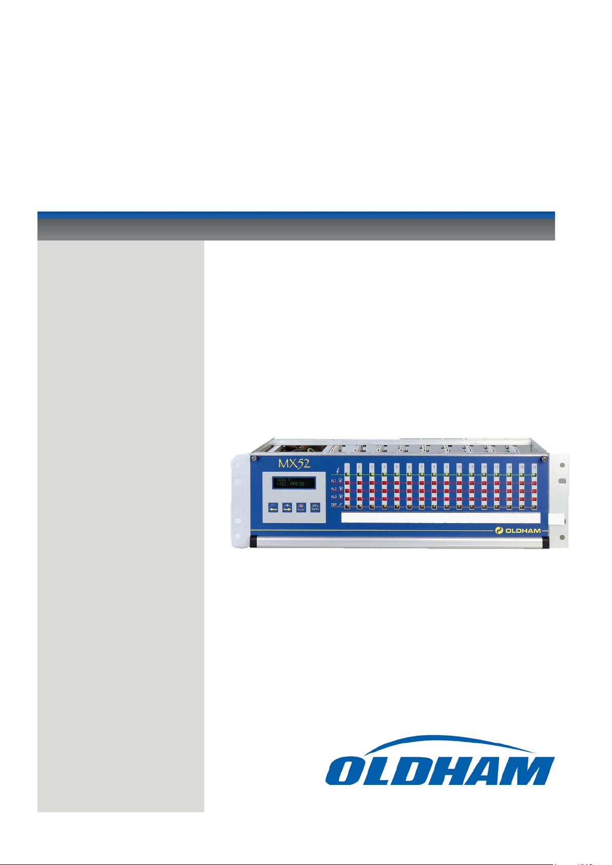
MX 52
MEASURING UNIT
Part Number: NP52UGB
Revision: B.0
The Fixed Gas Detection Experts
Page 2

Copyright April 2016 by Oldham S.A.S.
All rights reserved. The reproduction of all or any section of this document in any form whatsoever without
the written permission of Oldham S.A.S. is forbidden.
The information contained in this manual is accurate to our knowledge.
As a result of continuous research and development, the specifications of this product may be modified at
any time without prior notice.
Oldham S.A.S.
Rue Orfila
Z.I. Est – CS 20417
62027 ARRAS Cedex
Tel.: +33 (0)3 21 60 80 80
Fax: +33 (0)3 21 60 80 00
E-mail: info@oldhamgas.com
Website: http://www.oldhamgas.com
2
Page 3

EEXXTTEENNTT OOFF RREESSPPOONNSSIIBBIILLIITTYY
CCLLAAUUSSEESS CCOONNCCEERRNNIINNGG PPRROOPPEERRTTYY
WWAARRNNIINNGGSS
GGUUAARRAANNTTEEEE
GAS DETECTION
We are delighted that you have chosen an OLDHAM instrument and would like to thank you for your
choice.
We have taken all the necessary measures to ensure that your instrument provides total satisfaction.
Now it is important to read this document carefully.
* OLDHAM declines its responsibility towards any person for material damage, physical injury or death resulting
wholly or partly from inappropriate use, installation or storage of its equipment resulting from failure to observe
instructions and warnings and/or standards and regulations in force.
* OLDHAM neither supports nor authorises any company, physical or moral person to assume responsibility on
behalf of OLDHAM , even if it is involved in the sale of OLDHAM products.
* OLDHAM cannot be held responsible for direct or indirect damage or be required to pay direct or indirect
compensation resulting from the sale or use of any of its products IF THESE PRODUCTS HAVE NOT BEEN
DEFINED AND CHOSEN BY OLDHAM FOR THEIR SPECIFIC USE.
* Drawings, plans, specifications and information included in this document contain confidential information that is
the property of OLDHAM
* None of this information may be reproduced, copied, divulged or translated, by physical, electronic or any other
means, nor used as the basis for the manufacture or sale of OLDHAM equipment or for any other reasons without
prior consent from OLDHAM
* This document is not contractually binding. In the interests of its customers, OLDHAM reserves to modify the
technical specifications of its equipment without notice, in order to improve its performance.
* READ THIS MANUAL CAREFULLY BEFORE FIRST USE OF THE EQUIPMENT: this manual must be
read by any person who is or will be responsible for using, maintaining or repairing this equipment.
* This equipment will only provide the announced performance levels if it is used, maintained and repaired
according to OLDHAM directives, by OLDHAM personnel or by personnel approved by OLDHAM
2 years guarantee in normal conditions of use on parts and technical labour, return in our workshops, excluding
consumables (sensors, filters, etc.)
3
Page 4

4
Page 5

CONTENTS
1. DESCRIPTION.............................................................................................. 7
1.1. General............................................................................................................................. 7
1.2. Rack .................................................................................................................................. 8
1.3. The various printed circuit boards ................................................................................... 8
2. INSTALLATION AND CONNECTIONS .................................................. 9
.1. Installation: recommendations ............................................................................................ 9
.2. Electrical connections of the MX52 Unit (Fig. 8) ................................................................ 9
2.2.1. Alternative power supply ......................................................................................... 9
2.2.2. DC power supply ................................................................................................... 10
.3. Detectors (Figures 9 and 12) ............................................................................................. 10
2.3.1. Explosimetric detectors of PONT type .................................................................. 10
2.3.2. 3-wire detectors 4-20 mA: 3 connecting wires for shielded cable ......................... 11
2.3.3. 2-wire detectors 4-20 mA: 2 connecting wires for shielded cable ......................... 11
2.3.4. FIRE detectors: 2 connecting wires for shielded cable .......................................... 11
2.3.5. FLAME detectors: 2, 3 or 4 connecting wires for shielded cable depending on
utilization ............................................................................................................................... 11
2.3.6. CO2 detector of type “Ventostat VT” .................................................................... 13
2.3.7. Specific case of intrinsic safety detectors .............................................................. 13
2.3.8. Other detectors with standardized current output .................................................. 14
2.3.9. Parking application ................................................................................................ 14
.4. Connecting the unit to external devices ............................................................................. 15
2.4.1. Slaving controls...................................................................................................... 15
2.4.2. 4-20 mA current outputs (Fig. 12) ......................................................................... 16
2.4.3. RS 232 and RS 485 outputs ................................................................................... 16
2.4.4. Remote acknowledgement ..................................................................................... 18
3. STARTING UP ............................................................................................ 19
3.1. Checking the installation ............................................................................................... 19
3.2. Switching on the unit ...................................................................................................... 19
3.3. Operating modes ............................................................................................................ 20
3.3.1. Audio warning device (buzzer) .............................................................................. 20
3.3.2. Light-emitting diodes (LED) (Fig. 26) .................................................................. 20
3.3.3. Alarm thresholds .................................................................................................... 20
3.3.4. Fault thresholds ...................................................................................................... 25
3.3.5. Measuring unit ....................................................................................................... 26
5
Page 6

4. UTILIZATION ............................................................................................ 27
4.1. List and functions of the various items of “USER” equipment for programming and
calibration of the unit ................................................................................................................. 27
4.1.1. Keypad (see Figures 26 and 4) ............................................................................... 27
4.1.2. Maintenance keys ................................................................................................... 28
4.1.3. Potentiometers ........................................................................................................ 28
4.2. Menus ............................................................................................................................. 29
4.2.1. The various menus and their functions .................................................................. 29
4.2.2. Block diagram of the scrolling of the various menus ............................................ 29
4.2.3. Detailed flow diagrams of each menu.................................................................... 31
5. SETTING THE MX52 UNIT INTO SERVICE ....................................... 45
5.1. Programming the unit .................................................................................................... 45
5.2. Programming the measuring channels .......................................................................... 45
5.2.1. Programming .......................................................................................................... 45
5.2.2. Copy ....................................................................................................................... 46
5.3. Calibrations ................................................................................................................... 46
5.4. 4-20 mA output adjustment for a measurement channel ................................................ 50
6. MAINTENANCE ......................................................................................... 51
6.1. Periodic / preventive maintenance ................................................................................. 51
6.1.1. On the MX52 unit .................................................................................................. 51
6.1.2. On the detectors ..................................................................................................... 51
6.2. Failures: causes and remedies ....................................................................................... 52
6.3. Scrapping of MX52 ........................................................................................................ 55
6.4. List of spare and replacement parts ............................................................................... 55
7. VIEWS SPECIFIED IN THE MANUAL ................................................. 57
8. DETAILED TECHNICAL CHARACTERISTICS ................................. 87
9. Special Specifications for use in Potentially Explosive Atmospheres in
accordance with European Directive ATEX 94/9/EC. ....................................... 89
6
Page 7

11..
DDEESSCCRRIIPPTTIIOONN
MMAAIINN CCHHAARRAACCTTEERRIISSTTIICCSS
1.1. General
The MX52 measuring and alarm unit can be fitted with between one and 16 independent channels.
Each channel is connected to one or more detectors installed in the locations to be monitored.
The measurement that is output from the detector is displayed on the MX52 unit and compared with
alarm thresholds. If thresholds are exceeded, the unit actuates relays which can be used to control
external devices.
REMARK
The equipment of the MX52 unit comprises line PCBs, each equipped with two channels. However,
each channel is independent and can be connected to any type of OLDHAM detector provided that
the PCB is suitably programmed. The number of line PCBs is always equal to the mixed even
number greater than the number of channels used divided by two.
Rack 3U 19”
AC or DC power supply
16 measuring inputs for detectors
Display of measurement on a plasma display panel (2 lines - 16 characters)
One keypad with four keys for the user
One “CALIBRATION” key and one “PROGRAMMING” key for maintenance
(accessible only by opening the front panel)
3 gas alarms per channel
- Two instantaneous rising or falling thresholds, manual or automatic clearing, with
“extractor control logic (tunnel parking application)”
- One rising or falling threshold, automatic clearing, triggering by time delay or
average
Relaying
Total of 34 relays distributed as follows:
- Two relays per channel, with positive or negative safety, contacts open or closed
at rest for the first two thresholds
7
Page 8

- One relay common to channels for third thresholds or for all alarms (buzzer
transmission), with positive or negative safety, contacts opened or closed at rest
- One relay common to channels for faults and failures, constant positive safety
mode, contacts open or closed at rest.
Current output (4-20 mA) per measuring channel.
Common audio alarm that can be acknowledged in the case of occurrence of gas alarms.
1.2. Rack
The MX52 rack is of the 3U 19” type.
Overall dimensions: Fig. 1
Overall view, front profile: Fig. 2
Overall view, back profile: Fig. 3
1.3. The various printed circuit boards
Overall view: Fig. 4
Power board and module: Fig. 5
MICRO board: Fig. 6
Measuring channel board: Fig. 7
Front connection board: Fig. 4
8
Page 9

22..
IINNSSTTAALLLLAATTIIOONN AANNDD CCOONNNNEECCTTIIOONNSS
Please ensure you read the paragraph: Special Specifications for use in Potentially Explosive
Atmospheres in Accordance with European Directive ATEX 94/9/EC
.1. Installation: recommendations
The MX52 unit can be installed in any premises without an explosive atmosphere. They should
preferably be placed in a ventilated and monitored location (guardhouse, control room,
instrumentation room, etc.).
Attachment is to be ensured in accordance with the dimensions in Figure 1 (four attachment points).
REMARK
In order to permit the swivelling front panel of the unit to be opened completely, allowance must be
made for opening by rotation through 180° downwards.
Before making any connections, the unit should be switched off using the main On/Off switch
below and to the left of the FRONT circuit (see Figures 4 and 26).
.2. Electrical connections of the MX52 Unit (Fig. 8)
The MX52 unit is equipped with a pulse automatic device which enables to connect 24 V DC
voltage in a lack of 220 V AC voltage so we can use no expansive save power supply.
2.2.1. Alternative power supply
- Voltage: 230 V AC (207 to 244 V) 50/60 Hz
- Maximum power: 300 VA
- Maximum current in cable: 1.5 A
- Cable: 3 x 1.5 mm² (including earth)
- Location of connection terminal blocks: Fig. 8, item A
- Protection: the phase and neutral wires are protected by time-delayed 2 A
fuses located at the rear of the power module.
- Voltage: 103 to 122 V AC - 50/60 Hz on option
CAUTION
It is mandatory that the appliance must be earthed. A terminal is reserved for this purpose at the
back of the power module: see Fig. 5. This connection is required in order to ensure correct
operation of the following:
- mains power interference filter,
- protective devices against electromagnetic interference.
9
Page 10

CAUTION
Each channel is configured in the factory for a given type of detector (explosive gas, toxic
gas, fire or flame). If two different types of detector are interchanged, this may result in
the destruction of the central unit or of the detector.
REMARK
2.2.2. DC power supply
- Voltage: 21 to 30 V continue. The "-" from continue power supply is linked to
earth (and earth being linked to frame).
- Maximum power: 240 W
- Maximum current in cable: 12.5 A
- Cable: 2 x 2.5 mm² or 2 x 4 mm² depending on length
- Location of terminal block: see Fig. 8, item D
- Protection: by two fuses located at the back of the power module (Fig. 8, item E)
.3. Detectors (Figures 9 and 12)
- The detectors are linked by SHIELDED cables.
- The utilization of shielded cables is MANDATORY
- The earth braid of shielded cables must be connected to the earth at one end
only.
2.3.1. Explosimetric detectors of PONT type
Three connecting wires for a shielded cable.
Resistance of detector / unit cable: 16 ohms maximum per wire, i.e. 32 ohms in loop (1 km for cable
3 x 1.5 mm²).
Connection on MX52 unit: see Fig. 10
10
Page 11

2.3.2. 3-wire detectors 4-20 mA: 3 connecting wires for shielded cable
- Resistance of detector / unit cable: 16 ohms maximum per wire, i.e. 32 ohms in loop
(1 km for cable 3 x 1.5 mm²).
- Connection on MX52 unit: see Fig. 10.
2.3.3. 2-wire detectors 4-20 mA: 2 connecting wires for shielded cable
- Resistance of detector / unit cable: 32 ohms maximum per wire, i.e. 64 ohms in loop
(2 km for cable 2 x 1.5 mm²).
- Connection on MX52 unit: see Fig. 11.
2.3.4. FIRE detectors: 2 connecting wires for shielded cable
The current commercial designations are as follows:
- “Thermovelo” detectors of type EC 11 (sensitive to temperature variations)
- Ionic detectors of type EI 1 100 (sensitive to smoke)
- Optical detectors of type EO 1 100 (sensitive to smoke)
- Resistance of detector / unit cable: 28 ohms maximum per wire, i.e. 56 ohms in loop (2 km for
cable 2 x 1.5 mm²)
- Fire detectors can be detected in parallel to a maximum of five. The end-of-loop resistor
(2.7 K) is to be placed at the end of the line on the last detector.
- Connection on MX52 unit: see Fig. 11.
2.3.5. FLAME detectors: 2, 3 or 4 connecting wires for shielded cable
depending on utilization
REMARK
The detectors can be supplied with power either via the MX52 unit or by an auxiliary 24 V DC
source.
11
Page 12

These detectors can operate in standalone mode:
Model
20/20 U
20/20 UC
20/20 UB
20/20 LC
20/20 UNC
20/20 LBC
20/20 I
Type
of terminal
block
B C A C C C
A
24 V DC power supply and direct utilization of relay contacts in accordance with the technical
specification corresponding to the detector used.
The current commercial designations are as follows:
- model 20/20 U - analog - type UV - 752002 (sensitive to UV radiation)
- model 20/20 UC - analog - type UV (sensitive to UV radiation)
- model 20/20 UB - µP technology - type UV - 772002 (sensitive to UV radiation)
- model 20/20 UBC - µP technology - type UV (sensitive to UV radiation)
- model 20/20 LC - analog - type UV/IR (pyroelectric, combination of UV and IR
detectors)
- model 20/20 LBC - µP technology - type UV/IR (pyroelectric, combination of UV and
IR detectors)
- model 20/20 I - µP technology - triple IR detector - 780002 (pyroelectric, sensitive to IR
radiation)
These detectors are equipped with various types of terminal block (see table below).
- Resistance of cable / unit
- In the case of local 24 V DC power supply:
8.5 ohms maximum per wire, i.e. 17 ohms in loop
- In the case of power supply via the MX52 unit:
3 ohms maximum per wire, i.e. 6 ohms * in loop
4 ohms for detector 20/20 I (IR3)
- Connection on MX52 unit (ONE detector per measuring channel ONLY):
- detector equipped with a terminal block of type A: see Fig. 13
- detector equipped with a terminal block of type B: see Fig. 14
- detector equipped with a terminal block of type C: see Fig. 15
Example of the utilization of the 4-20 mA signal from flame detectors equipped with connectors of
type A or C: see Fig. 16.
Example of the utilization of detectors equipped with connectors of either type A or type B and with
auxiliary power supply. The auxiliary power supply must be able to supply power to the number of
detectors planned in the measuring loop (see Fig. 17).
12
Page 13

REMARK
In classified areas, the installation must comply with the standards in force.
IMPORTANT
All intrinsic safety installations must be APPROVED as a whole assembly by an approved
organization (DRIRE, etc.).
REMARK
In the case of this application, the maximum of five flame detectors can be connected in the
measuring loop.
Example of the utilization of IR3 or UV/IR detectors equipped with connectors of type A with a
local junction box and galvanic insulation (see Fig. 18).
2.3.6. CO2 detector of type “Ventostat VT”
- Connection on MX52 unit: see Fig. 20.
- Resistance of detector/unit power cable: 12 ohms maximum per wire, i.e. 24 ohms in
loop.
- 4-20 mA output: maximum load = 280 ohms (whole loop)
2.3.7. Specific case of intrinsic safety detectors
Two types of intrinsic safety barrier can be used: Z787 / EX and MTL787S+.
PRECAUTIONS
Before connecting the barrier to the unit, check that the voltage is < 25 V DC.
- A short circuit in the electrical connections will result in destruction of the barrier.
- Perform wiring in the DE-ENERGIZED state.
- The electrical link between the MX52 unit and the clipper is made using a screened
cable with two active conductors with a maximum resistance of 12 ohms each.
- Connections on MX52 unit: see Fig. 21.
13
Page 14

Type of IS
barrier
Reference
Specific features
OLDHAM box
reference
Z787 / EX
6184703
To be fitted on DIN
RAIL
MTL787S+
6797100
To be fitted in an
approved box:
MANDATORY
For 2 clippers
6797192
For 5 clippers
6797547
For 12 clippers
6797101
OLDHAM “INTRINSIC SAFETY” BARRIERS
2.3.8. Other detectors with standardized current output
Any detector (with 2 wires or 3 wires) that can be supplied with power between 19 V DC and 32 V
DC and that supplies a standardized current (signal) of between 4 and 20 mA can be connected to
the MX52 unit.
The connection requirements are identical to those for the corresponding OLDHAM detectors (see
Fig. 22).
2.3.9. Parking application
CTX300 "Co parking" toxic gas detectors can be fitted in parallel when a mean gas concentration is
to be obtained. The detectors must, imperatively, be located in the same area. In this case, a
maximum of five detectors can be connected (see Fig. 23).
14
Page 15

.4. Connecting the unit to external devices
2.4.1. Slaving controls
The 16 measuring channels of the MX52 unit are each equipped with two relays which can be used
to control external devices: sirens, solenoid valves, extractors, telephone calls, etc..
For each measuring channel, the relays are distributed in the following manner (see Fig. 7):
- a relay associated with the triggering of alarm 1,
- a relay associated with the triggering of alarm 2,
- use of open or closed contacts selected with a jumper (see Fig. 7),
- use of positive or negative safety selected by programming (see the CHANNEL
programming menu),
- contact outputs on the back of the measuring board (see Fig. 12).
- An example of connection is given in Fig. 24:
- a siren connected to relay AL1 will be actuated as soon as alarm 1 is triggered,
- a solenoid valve connected to relay AL2 will be actuated as soon as alarm 2 is
triggered.
For all channels:
- A common relay associated with the triggering of alarm 3 for the 16 channels.
By programming, this common relay can also be used for the remote transmission of the
audio warning signal. (This relay will then be associated with all the unit’s alarms). The
3 contacts are available back to power supply module (fig 8).
- A fault relay associated with the triggering of channel faults (detector failures, electrical
connections, excessively negative zero, etc.). This relay will always be in positive safety
mode (see Fig. 5). The use of open or closed contacts is selected by programming on
common board.
- Common relay contact outputs on the back of the power module: Fig. 8.
REMARK
Owing to the breaking capacity of the MX52 unit’s relays which is limited to 2 A / 250 V AC or 30
V DC, external intermediate relays must be used if the devices to be controlled require high power
levels.
15
Page 16
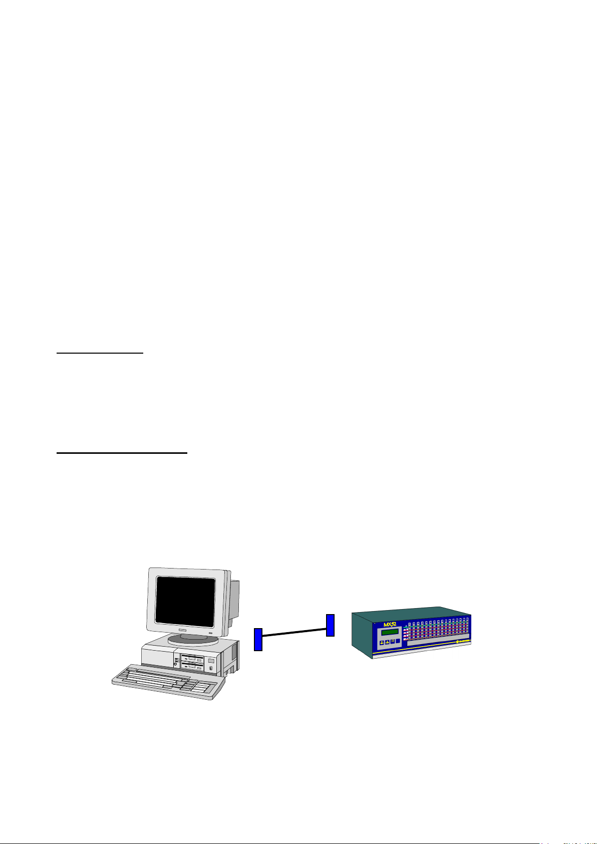
2.4.2. 4-20 mA current outputs (Fig. 12)
MX52
ORDINATEUR PC
Cordon liaison PC/MX52
Female DB9
Male DB9
MX52
PC COMPUTER
For each measuring channel, the MX52 unit is equipped with a 4-20 mA output that can be used to
retransmit measurements to a recorder or an external PLC. The maximum resistance in loop mode is
600 ohms. The earth connections for the 4-20 mA outputs are common and the unit. The 4-20 mA
lines are not galvanically insulated one from the other. The current output varies according to the
measurement and has several states, as follows:
- On starting up the unit: I < 1 mA
- With FAULT: I < 1 mA
- In MAINTENANCE mode: I = 2 mA
- ZERO MEASUREMENT: I = 4 mA
- Full scale: I = 20 mA
- Out of range or “in doubt”: I > 23.2 mA
An example of the connection of a multi-channel recorder is given in Fig. 25.
2.4.3. RS 232 and RS 485 outputs
RS232 OUTPUT
A computer can be connected on a female sub.D/DB9 type connector located on the back of the
micro board (fig6 repA). The MX52 programming, from outside, will be possible thanks to this
connection.
RS 232 OUTPUT USING
- Remove the DB9 connector (pmug with an internal strap)
- Connect a link cable ref.6315831 which will link the monitor to the computer on the
MX52 available female connector DB9 (repA Fig6)
- when the using is stopped : no connect the cable and put the male DB9 "plug" again.
16
Page 17

RS 485 OUTPUT (PINABLE ON FIG 29)
Several MX52 units can be linked to a single computer, which is the "master" of the network. In
this case, a "SLAVE NUMBER" (by programming/unit) is asigned to each MX52 unit.
This RS 485 output can be galvanically insulated as an option.
1st case : no galvanic insulation
- no mounted insulation component
- 2 polarization electrical resistances are programmed and welded
2nd case : with galvanic insulation
- mounted and welded insulation component
- no programmed polarization electrical resistance for "plu" (+ 5V)
a) with RS 485 shielded
- no programmed polarization resistor for "moins" (GND)
b) without RS485 shielded
- programmed polarization resistor for "moins" (GND)
End loop resistor
It is located on the MX52 micro board and must be programmed with the last MX52 unit of the
loop (by pins) with a 120 Ohms value.
The MX stored data are some instantaneous values
The RS485 output is a half duplex type.
RS 485 OUTPUT USING
- No change the sub D/DB9 "plug" connector
- Connect the screwed connector terminals 3,4 and 5, located on the back of the MX52
unit (repB Fig6). See connection details fig 29.
- Owing to mounted wires or not (following the mounting and the equipment linked or not
on the earth…).
17
Page 18

IMPORTANT
All details regarding the RS 485 complete description (Modbus / Jbus format, structures,
adresses aso…) are developped in a leaflet ref. D 813 577.
CAUTION
A computer must be used in order to printout the data stored by the MX52 unit.
Several MX52 units can be connected to a single computer which is the "MASTER". In this
case, a SLAVE number is assigned to each MX52 unit.
2.4.4. Remote acknowledgement
It is possible to allow remote acknowledgement by connecting on connector 5 plugs, on the back or
the micro board : see fig 6 item B.
18
Page 19

33..
SSTTAARRTTIINNGG UUPP
CAUTION
OLDHAM is not responsible for the compliance of the complete electrical safety system.
CAUTION
The handling operations and adjustments described in these paragraphs are strictly
reserved for authorized personnel as they are liable to affect detection safety.
3.1. Checking the installation
It is checked that, at least, all connections have been made and that the complete installation
complies with current standards in force.
The MX52 unit is switched on by means of circuit breakers * provided for that purpose and which
ensure protection of the mains power unit.
* The circuit breakers are to be selected according to the power consumption levels specified by the
manufacturer and the length of the electric cables.
3.2. Switching on the unit
To start up the MX52 unit, you must:
- swivel the front panel,
- press the ON/OFF button located to the bottom left-hand side of the FRONT
circuit: see Figures 4 and 26 (item A).
- The display panel then shows, for example:
MX 52 V2.0
The unit then goes into INITIALIZATION mode for one minute. Consequently, all the alarms are
inhibited and the current outputs are 1 mA for the channels in service. The unit then performs a selftest * on its buzzer and all its night-emitting diodes. At the end of this one-minute period, the
channels in service return to normal operation and the corresponding alarms and relays are enabled.
* The user can carry out a “manual-self test” by pressing the test key at any time (see Fig. 26).
This self-test lasts 20 seconds and the display panel may show the following displays one after the
other, for example:
19
Page 20

LED
Extinguished
Illuminated
in steady mode
Flashing
GREEN
Channel not in
service
Channel in service
Threshold AL1 exceeded
(manual clearing) and not
acknowledged
1st red
AL1 not triggered
Threshold AL1 exceeded
(automatic clearing)
Threshold AL2 exceeded
(manual clearing) and not
acknowledged
2nd red
AL2 not triggered
Threshold AL2 exceeded
(automatic clearing)
3rd red
AL3 not triggered
Threshold AL3 exceeded by mean
or time (automatic clearing)
Yellow
No fault
Fault on channel
-Channel being calibrated or
programmed
- Detector being calibrated
MX 52 v2.
xx LEL CH4
*** SELF-TEST ***
xx LEL CH4
Line corresponding to
the channel displayed
when the ENTER key
was pressed
then
The user can interrupt the self-test cycle before it is completed by pressing the
ACKNOWLEDGEMENT key.
3.3. Operating modes
In normal operation, the audio warning device is triggered whenever a fault or an alarm appears.
The audio warning device can be stopped by pressing the ACKNOWLEDGEMENT key or by
remote acknowledgement. The buzzer makes a continuous or discontinuous sound (according to the
programming of the unit) if an alarm threshold is exceeded.
Each channel is equipped with five LEDs (visible and identified on the FRONT panel).
3.3.1. Audio warning device (buzzer)
3.3.2. Light-emitting diodes (LED) (Fig. 26)
3.3.3. Alarm thresholds
Each of the three alarm thresholds can be programmed independently for each channel. (See the
“Channel programming” menu).
20
Page 21

In normal operation, a gas alarm is only triggered after a preprogrammed time delay in order to
avoid spurious alarms.
Alarm thresholds can be processed in the following manners:
- in normal cycle with manual clearing: block diagram 1,
- in normal cycle with automatic clearing: block diagram 2,
- in parking cycle: block diagram 3.
The alarm thresholds are to be selected according to the gases detected and the corresponding
standards in force.
Special case: A channel connected to a fire detector
- It is MANDATORY to select the scale with 100 divisions.
- It is MANDATORY to select the alarm threshold with 60 divisions.
(Owing to the end-of-loop resistor of 2.7 k, the fire detector outputs 4 mA when no fire is detected
and 20 mA if a fire is detected).
21
Page 22
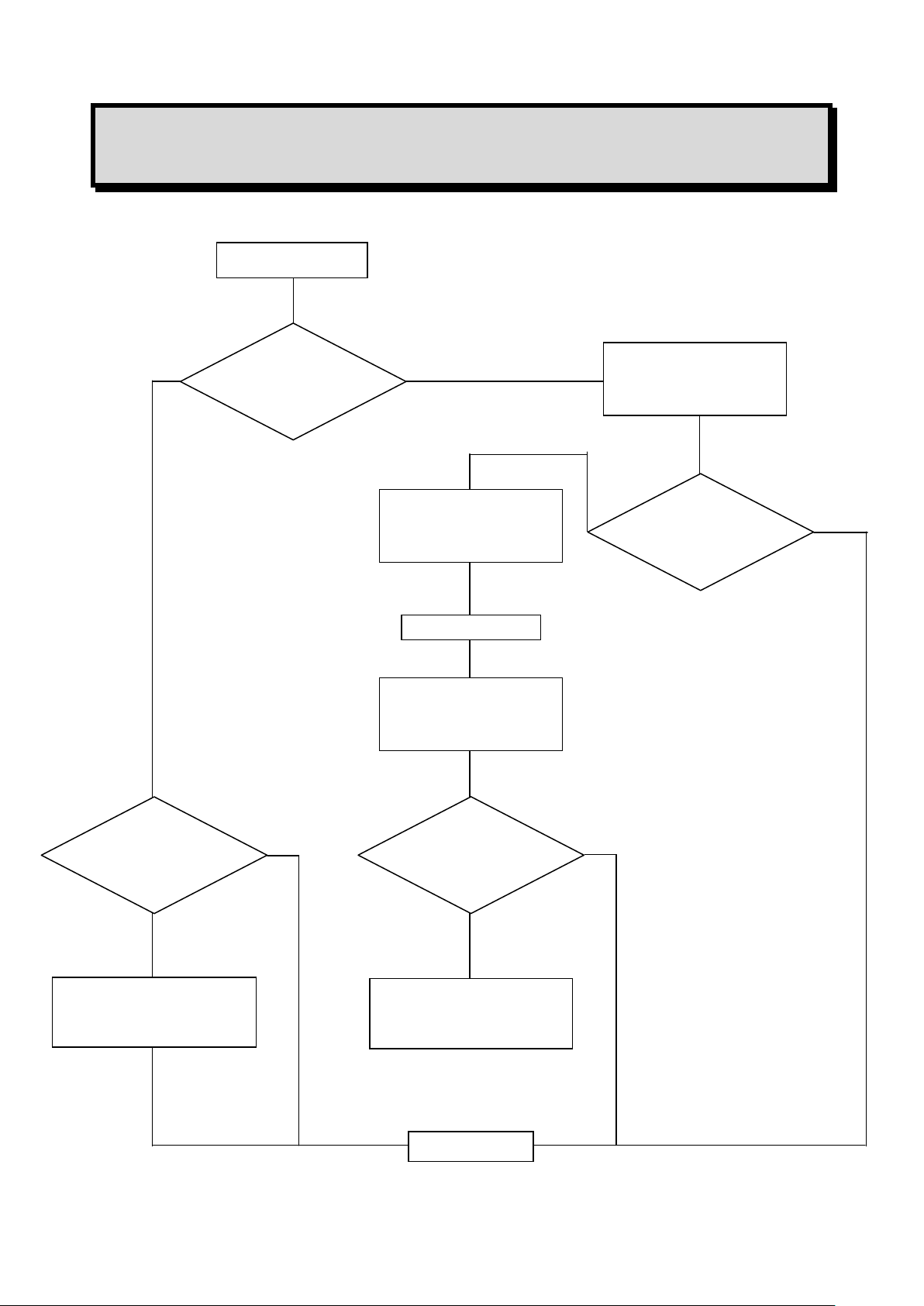
Alarm
acknowledged
LED extinguished
Relay disengaged
Buzzer stopped
No
Illumination of flashing
alarm LED
After T2 time
START
Threshold
exceeded
Time T1
exceeded
Illumination of flashing
alarm LED
LED steady mode
Buzzer stopped
END
Relay engaged
Buzzer engaged
No
No
No
Yes
Yes
Yes
Yes
Alarm
acknowledged
BLOCK DIAGRAM 1
NORMAL CYCLE WITH MANUAL CLEARING
22
Page 23
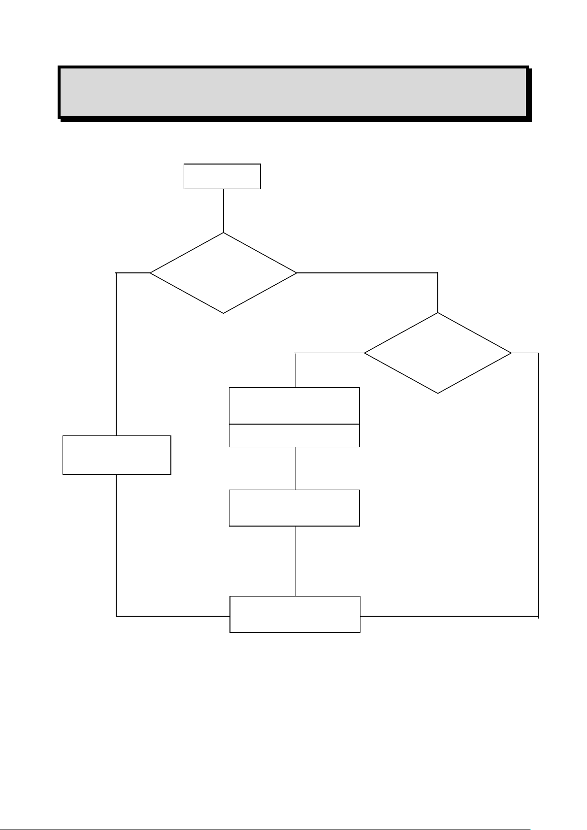
START
Threshold
exceeded
Time T1
exceeded
LED extinguished
Relay disengaged
Alarm LED illuminated
in steady mode
After T2 time
Relay engaged
Buzzer engaged
END
Yes
No
No
Yes
BLOCK DIAGRAM 2
NORMAL CYCLE WITH AUTOMATIC CLEARING
23
Page 24
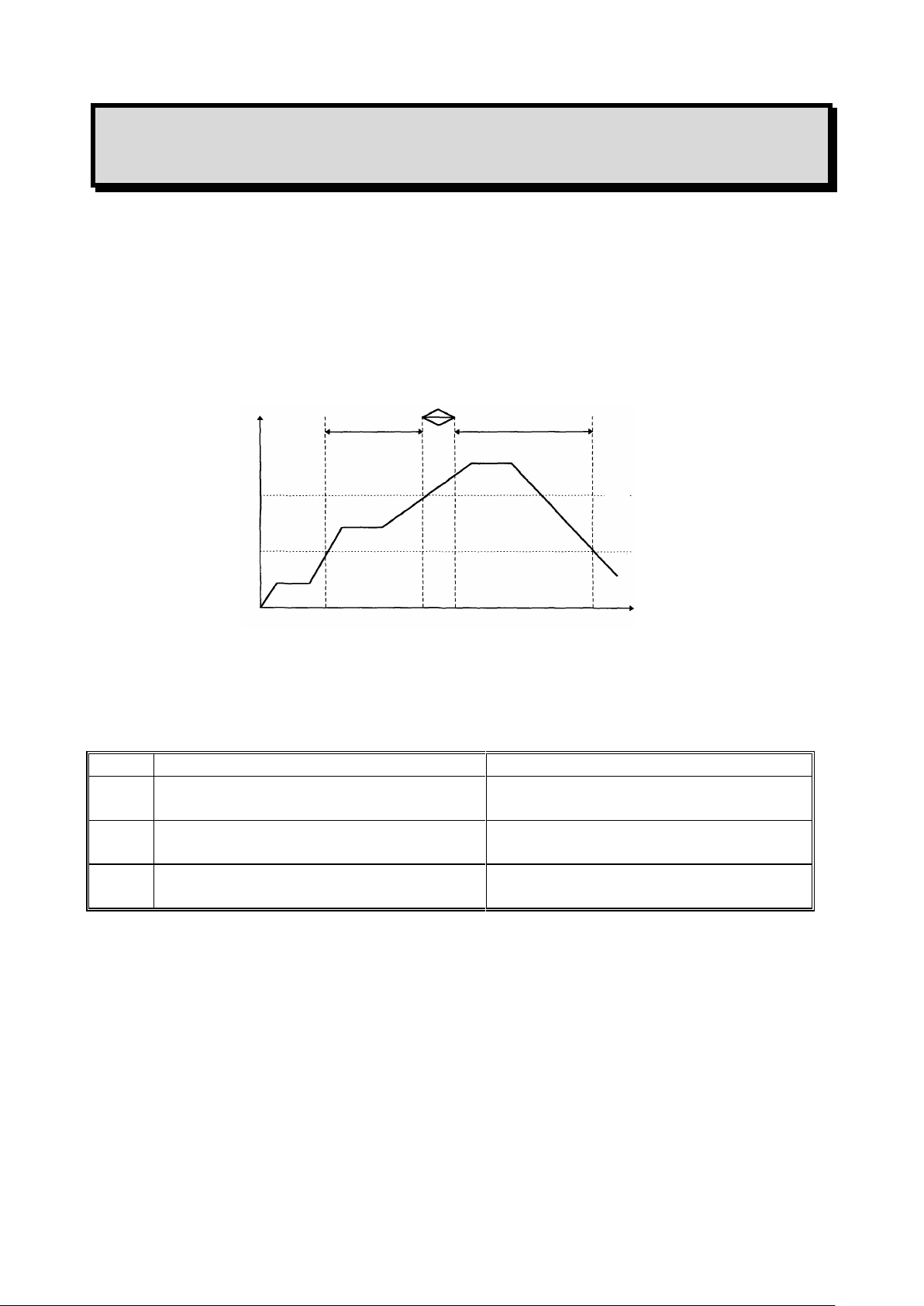
t AL1
tR1 R2
t AL2
Threshold AL2
Threshold AL1
Starting of
relay R1
Stopping
of relay R1
Starting of
relay R2
Stopping of
relay R2
min.
t
AL1
Min. operating time for alarm 1
(defined for each channel)
t1
t
AL2
Min. operating time for alarm 2
(defined for each channel)
t2
t
R1 R2
Switching time from relay 1 to relay 2
(defined for the whole unit)
t
R1 & R2
BLOCK DIAGRAM 3
PARKING CYCLE
Alarm 3 operates in the same way as the normal cycle.
The times defined for alarms 1 and 2 (time delays) are, in this case, used to define the minimum
operating time for each relay.
24
Page 25
3.3.4. Fault thresholds
END
START
Wait until the fault has been present
for at least 5 seconds.
The relays are locked in their current state.
The common fault relay is engaged.
The buzzer is engaged.
The channel fault LED is illuminated. *
1 mA is sent on the 4-20 mA output.
Processing of detector faults
Each channel detects the following faults.
For toxic and explosive gas detectors:
- line interrupted (0 mA),
- line short-circuited or excessive consumption,
- negative offset (more than 20% of measuring scale),
- line in calibration mode (2 mA) (if confirmed by programming).
For detectors of the explosive gas type (4-20 mA and 340 mA) in normal mode and if the
measurement is greater than 100% of the measuring scale, there are the following immediate
results:
- Display: SUP
- The relays are actuated if the thresholds are reached.
- The general fault relay is actuated.
- The 4-20 mA output of the channel is greater than 20 mA.
- ALl these states are memorized and the only way of acknowledging them is to
switch off the channel and then restart it.
Faults are valid after a preprogrammed time (in the same way as alarms).
FAULT BLOCK DIAGRAM
* The LED is extinguished as soon a the fault disappears.
25
Page 26

Channel 1
x x LEL CH4
Channel 2
x x x ppm CO
Channel 5
x x x ppm CO
normal scan
x x x ppm CO
3.3.5. Measuring unit
One minute after starting up, and if no test action is performed on the keypad, the unit successively
scans all the channels in service and displays the measured values.
Examples of display
OR
- Each channel is interrogated for 10 seconds.
- The user can interrogate a channel manually by selecting that channel with the + and -
keys to obtain a manual display for one minute.
- The user can return to normal cyclic scanning during that one-minute period by
simultaneously pressing the + and - keys. The display panel then shows alternating
displays, three times in succession:
For example:
then
26
Page 27
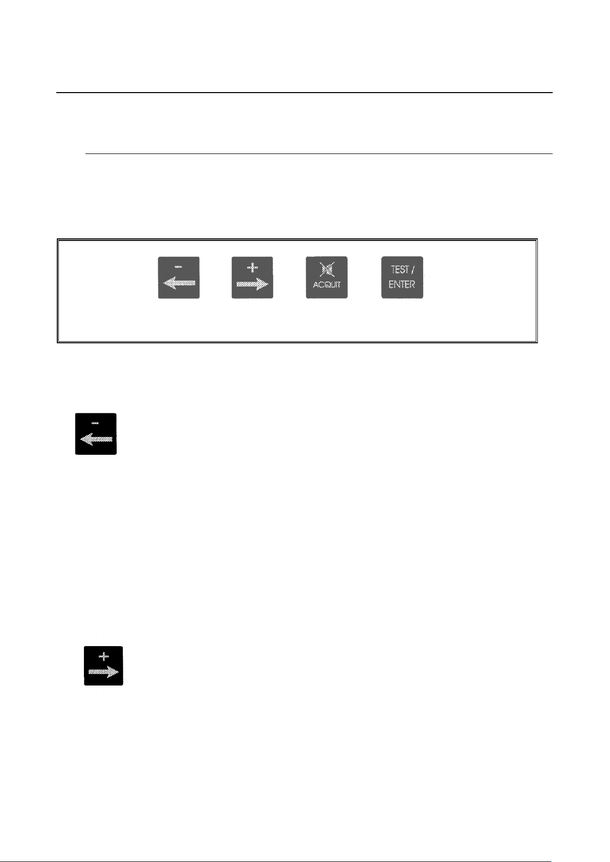
44.. UUTTIILLIIZZAATTIIOONN
Item D, Fig. 26
- Manual display of previous channel
- Combined with the “PLUS” key to restart the channels
automatic display cycle.
MAINTENANCE MODE
- Manual display of previous channel
- Decrease value, threshold, etc.
- Display of previous choice (onoff, etc.)
- NO
- Manual display of next channel
- Combined with the “MINUS” key to restart the
channels automatic display cycle.
MAINTENANCE MODE
- Manual display of next menu
- Increase value, threshold, etc
- Display of next chooice (onoff, etc)
- YES
4.1. List and functions of the various items of “USER” equipment for
programming and calibration of the unit
4.1.1. Keypad (see Figures 26 and 4)
This is equipped with four touch keys accessible without opening and swivelling the MX52 unit’s
FRONT panel or opening and swivelling the FRONT panel for maintenance.
NORMAL MODE
NORMAL MODE
27
Page 28
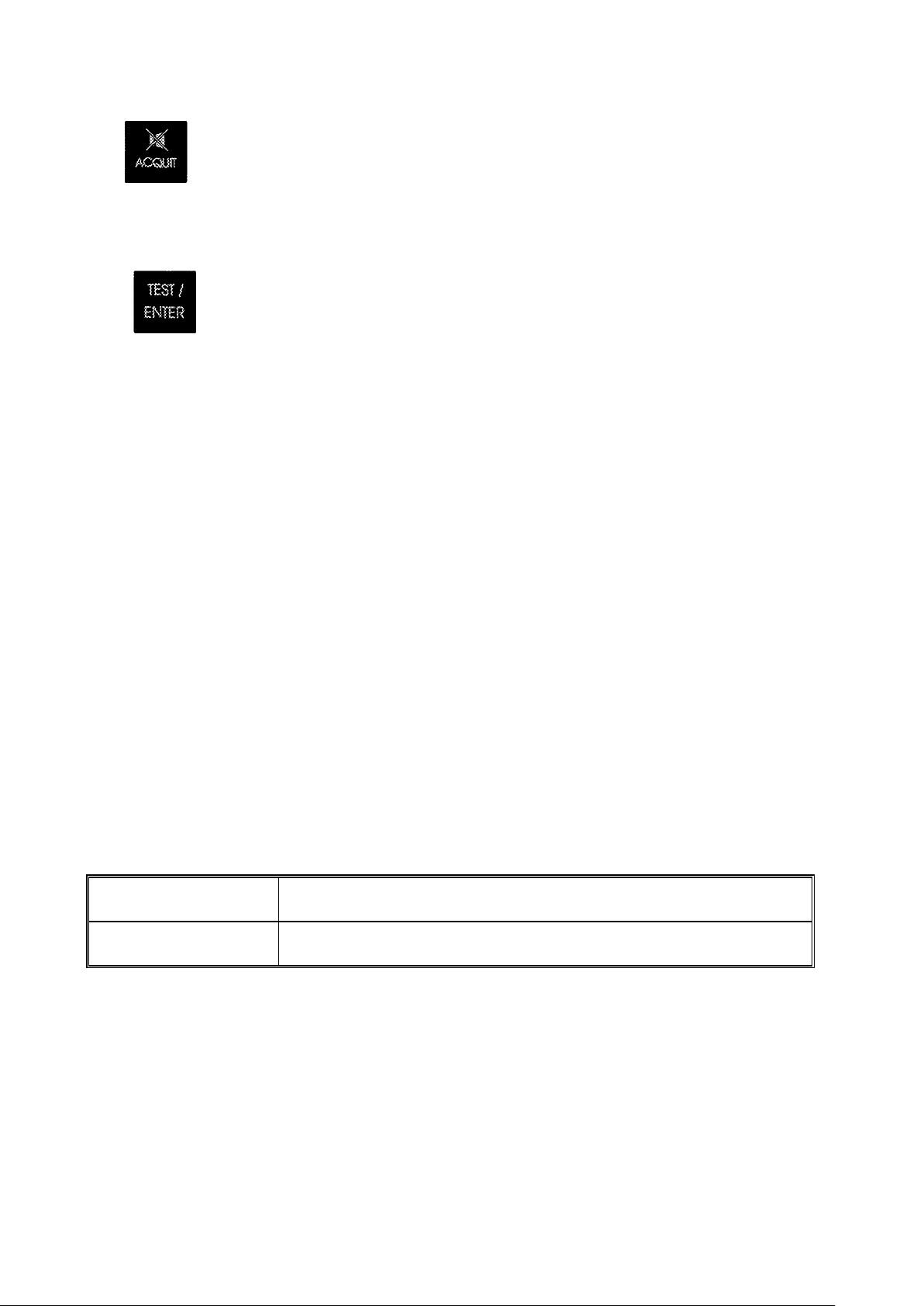
- “Audio and visual” or “audio” clearing of an alarm
- Exit from a current menu
- Start a self-test manually
- VALIDATE
TOP (item A)
1 detector ZERO potentiometer
1 detector sensitivity potentiometer
BOTTOM (item B)
1 potentiometer 4 mA / current output
1 potentiometer 20 mA / current output (for full scale)
4.1.2. Maintenance keys
PROGRAMMING key (item B, Fig. 26): accessible after opening and swivelling the front panel.
- Combined with the “-” key to go back in a menu.
- To quit normal display mode and access the various menus (see block diagram of
the various menus).
- To scroll through a menu.
CALIBRATION key (item C, Fig. 26): accessible after opening and swivelling the front panel.
- To set a channel to CALIBRATION mode.
- To quit that mode.
4.1.3. Potentiometers
On the FRONT circuit, each measuring channel has four potentiometers (item E in Figures 26 and
27). These are accessible by opening and swivelling the FRONT panel of the MX52 unit and are
laid out as follows (see Fig. 27):
28
Page 29

DESIGNATION
FUNCTION
“CHANNEL” programming
- To program the whole configuration of a measuring
channel (ON/OFF, range, alarm thresholds, etc.)
“SIMULATION” programming
- To artificially vary a channel measurement on:
- the display panel,
- the 4-20 mA current output.
- To trigger the alarms (LED and relays) at the same
time.
“CHANNEL COPY” programming
- To copy the complete programming from one channel
to another (time saving)
“UNIT” programming
- To program the whole configuration of the MX52 unit
(language, slave number, etc.).
“UPLOADING” programming
- To transfer data, measurements and events, etc., from
the unit to a computer via the MX52 unit’s RS 485 / J
BUS output.
4.2. Menus
4.2.1. The various menus and their functions
The MX52 unit has five menus that are accessed by pressing the “Programming” key (item B, Fig.
26).
These five menus are as follows:
4.2.2. Block diagram of the scrolling of the various menus
It is easy to use these various menus by means of the keys on the keypad and the “Programming”
key (items B and D, Fig. 26).
Detailed flow diagrams of the menu scrolling function and of each menu are given on the following
pages.
29
Page 30

NORMAL
DISPLAY
P
Programming
[Channel x x]
+
-
Programming
Simulation
+
-
Programming
Channel xx copy
+
-
Programming
Unit
+
-
Programming
Uploading
P
+
-
SCROLLING OF THE VARIOUS MENUS
REMINDER (Fig. 26)
Programming key
Keys used to move
30
Page 31

+
-
++++++
E N T E R
+
+
E N T E R
+
-
+
-
Seuil Alarme 1
[25]
Measuring range
[100]
Programming
[Channel xx]
Alarm 1 threshold
[25]
NORMAL
DISPLAY
Channel xx
[Off]
Alarm 2 threshold
[50]
Decimal point
[1.]
P P P
P
P
P
4.2.3. Detailed flow diagrams of each menu
CHANNEL PROGRAMMING
Remove on the programming socket before entering into programming
: last channel displayed
: Off On
then ENTER
: CHOICE OF RANGES
10 30 100 300 1000 2000 xxxxU
then
: SELECTION OF POINT POSITIONING
100 10.0 1.00 0.100 0.010 0.001
+++
then
: 0 to 2000
then ENTER
: 0 to 2000
then ENTER
31
Page 32

+
-
-
+
-
+
-
+
-
+
Cycle
[Normal]
P
Alarm 2
[Increasing]
Alarm 3 threshold
[75]
Alarm 1
[Increasing]
Alarm 3
[Increasing]
P P P
P
P
: 0 to 2000
then ENTER
: Increasing Decreasing
then ENTER
: Increasing Decreasing
then ENTER
: Increasing Decreasing
then ENTER
: Normal Parking
then ENTER
32
Page 33

-
+
-
+
-
+
-
+
Alarm 3
[Time delay]
Ack alarm 1
[Manual]
Ack alarm 2
[Manual]
Relay 1 safety
[Negative]
P P P
P
: Manual Automatic
then ENTER
: Manual Automatic
then ENTER
: Time delay Mean
then ENTER
: Negative Positive
then ENTER
33
Page 34

-
+
E N T E R
-
+
+
E N T E R
-
+
+
E N T E R
-
+
+
E N T E R
-
+
+
E N T E R
Relai 2
[Free]
Relay 2 safety
[Negative]
Relay 1
[Free]
Relay 3
[Free]
Fault relay
[Free]
P P P
P
Negative Positive
then
Free Set to 0 Set to 1
then
Free Set to 0 Set to 1
then
Free Set to 0 Set to 1
then
Free Set to 0 Set to 1
then
34
Page 35

-
+
E N T E R
+
-
E N T E R
-
+
+
E N T E R
-
+
+
E N T E R
-
+
E N T E R
-
+
E N T E R
-
+
E N T E R
Gas
[CH4]
Cal detection
[No]
Channel xx
[Premises 1 channel] U
Units
[LEL]
Alarm 2 time
[00:00:00]
Alarm 1 time
[00:00:00]
P P P P P
P
Alarm 3 time
[00:00:00]
P
P
H mn sec
H mn sec
H mn sec
flashing
The MX52 unit can detect and indicatez (with a flashing
yellow LED) that a line has-been placed in
CALIBRATION mode on the detector.
No Yes
then
Free display: A channel heading can be programmed
(in 13 characters maximum). By default, the channel
number is displayed in this area.
then
CH4 CO 2S etc.
then
LEL % ppm etc.
then
Time: Time interval between the triggering of the AL
LED and of the corresponding relay, or the minimum
operating time of the relay in parking mode.
then
Display of time by using keys
then
Texte
then
35
Page 36

-
+
+
E N T E R
This key can also be used to exit from the current menu.
-
When in a menu, you can go back (to make checks or modifications,
etc.) by pressing and holding Programming key and by successively
pressing and releasing the down key- .
[ ]
Parameters specified in square brackets [ ] are the VALID parameters
(in memory).
(1) Free
This means that the relay can be activated when programming alarm
thresholds are triggered.
Set to 0
This means that the relay is not powered supply, and will not be
activated by MX52 control unit with alarm..
Set to 1
This means that the relay is always powered supply (by the MX52
control unit), and neither will not be activated by MX52 control unit
with alarm. Using of relays will be directly programmed by J-BUS
input and "COM52" software.
Detector type
[Explosive]
End of menu
P
P
INFORMATION
(Bridge) (4-20 mA)
(1)
(Fire)
(2)
: Explosive Toxic Spec. tox.
then
(1) in case of "Up" fault : 3 "gas" alarms and fault alarm are triggered.
(2) In case of "Up" fault : only the fault alarm is triggered.
36
Page 37

DESIGNATION
MEANING
LEL
Lower explosive limit
%
Percent
ppm
parts per million
ppb
parts per billion
UEG
Unter Explosion Grenze (= LEL in German)
LEL
Limite inférieure d’explosivité (= LEL in
French)
bar
unit of pressure
mb
unit of pressure (millibar)
Rh
relative humidity
m/s
metres per second
mg
unit of weight (milligram)
unit + flashing U
free indication of unit
-
+
then
E N T E R
LIST OF UNITS
37
Page 38

LIST OF GASES
DESIGNATION
MEANING
CH4
Methane
CO
Carbon monoxide
H2S
Hydrogen sulphide
N
Nitrogen
NO
Nitric oxide
NO2
Nitrogen dioxide
SO2
Sulphur dioxide
CI2
Chlorine
H2
Hydrogen
HCL
Hydrochloric acid
HCN
Hydrocyanic acid
NH3
Ammonia
ETO
Ethylene oxide
PH3
Phosphine
HF
Hydrofluoric acid
CFC
Freons
CO2
Carbon dioxide
ASH
Arsine
SiH4
Silane
BUT
Butane
PRO
Propane
GNT
Natural gas
ETY
Ethylene
PNT
Pentane
HEX
Hexane
PRY
Propylene
ACY
Acetylene
ETA
Ethanol
ACO
Acetone
OPR
Propylene oxide
OET
Ethylene oxide
ISB
Isobutane
DIM
Dichloromethane
AET
Ethyl alcohol
BUN
2-Butanol
ISP
Isopropanol
XYL
Xylene
TOL
Toluene
ESS
Petrol (gasoline)
BUD
Butadiene
HYD
Hydrogen
Gas + flashing U
Free indication of name of gas:
-
+
then
E N T E R
38
Page 39

SIMULATION PROGRAMMING MENU
Simulation on previously displayed and
[validated] channel
Free labelled area
S = flashing to indicate that this channel is in
simulation mode.
To artificially vary measurement on the display
panel, and trigger alarms (LED and relays)
= ESCAPE (ECHAPPE)
To exit from this menu and return to normal
operation
Programming
[Simulation xx]
NORMAL
DISPLAY
P
P
Channel xx
LEL CH4 S
Programming
[Simulation xx]
ACK
ENTER
+
-
+
END OF MENU
39
Page 40

Last channel displayed
Validation of menu
Validation of channel to be copied
: Copy the channel’s configuration to
another channel
xx = indication of “Other channel
number” using keys
-
+
: Validation of copy
Programming
Copy channel xx
NORMAL
DISPLAY
P
P
Copy channel
[Channel xx => xx]
Programming
[Copy channel xx]
Copy channel
[Channel xx => xx]
ENTER
+ + ENTER
END OF MENU
COPY PROGRAMMING
40
Page 41

Validation of menu
Choice of languages:
: French English German Spanish
+
+
+
then
E N T E R
Choice of transmission speed with
computer:
1200 2400 4800 9600 19200 Bauds
++++
then
E N T E R
Choice of slave address (this unit)
0 to 250
+
then
E N T E R
NORMAL
DISPLAY
P
P + +
+
Programming
Unit
P
P
P
Language
[French]
Programming
[Unit]
Speed
[9600]
Slave address
[1]
ENTER
UNIT PROGRAMMING
41
Page 42

This is the time interval between exceeding of the
AL threshold and triggering of the corresponding
visual alarm (LED).
Display the time using keys:
-
+
then
E N T E R
In “Parking” mode: this is the time interval between
stopping of relay 1 and starting up of relay 2.
Display the time using keys:
-
+
then
E N T E R
Negative Positive
-
+
then
E N T E R
Control of relay 3 (common) by any triggering of
buzzer
NO YES
-
+
then
E N T E R
Utilization of common audio alarm (buzzer)?
(Function in series with buzzer jumper)
NO YES
-
+
then
E N T E R
YES = If copy of buzzer on alarm 3 and with buzzer
option into service : audible alarm will be triggered
when there is an alarm.
NO = The common audible alarm (buzzer) will be
triggered for a 30 seconds maximum time (even
there is an alarm).
-
+
then
E N T E R
Response time
[00 : 00 : 00]
P P P
P
P
Relay safety
[Negative]
Relay 1&2 stop T
[00: 00 : 00]
Buzzer transferred
[NO]
Buzzer connected
[NO]
Continuous buzzer
[NO]
END OF MENU
H mn sec
H mn sec
42
Page 43

*******
**
*************
*********************
*
*********************
****
*********************
*******
*******
****************
***
*** + +
+
UPLOADING PROGRAMMING
Only OLDHAM personnel and personnel approved by OLDHAM can be made this operation.
Display of menu
Validation of utilization of
menu
Display of menu
confirmation
Data transfer request
Validation of data transfers
Confirmation of uploading
43
Page 44

44
Page 45

55.. SSEETTTTIINNGG TTHHEE MMXX5522 UUNNIITT IINNTTOO SSEERRVVIICCEE
REMINDER
The handling operations and adjustments described in this chapter must be performed by
authorized personnel only, as they are liable to affect detection safety.
Once the measuring unit has been switched on, it can be programmed (1), its measuring channels
can be programmed (1) according to the detectors used and calibrations can be made on the unit and
detectors.
(1) These programming operations can be carried out directly on the MX52 unit in accordance with
the following procedures or using a computer equipped with the “com 52” software.
5.1. Programming the unit
To program the MX52 measuring unit, and according to the required specifications, the “Unit
programming” menu must be used (see Section IV-2 on Menus) by means of the keypad and the
“Programming” key. Then, the instructions in the menu should simply be followed.
CAUTION
If the unit remains in programming mode for more than 30 minutes, it automatically switches to
fault mode.
5.2. Programming the measuring channels
5.2.1. Programming
To program each measuring channel according to the type of detector used and the required
specifications, the “Channel programming” menu must be used (see Section IV-2 on Menus) by
means of the keypad and the “Programming” key. Then, the menu instructions should simply be
followed.
REMARK
When a channel is switched on, all its relays are in “off” mode and its current output is 1 mA. Then,
one minute later, the channel comes into effective operation (relays ready and output of 4-20 mA).
CAUTION
If a channel remains in programming mode for more than 30 minutes, it is automatically switched
to fault mode.
45
Page 46

Case 1
Measuring channel connected to a detector with no integrated electronics (explosive gas
detector).
5.2.2. Copy
In order to make the programming of ALL CHANNELS less TIME-CONSUMING when the same
programming is required for a number of channels, it is recommended that the “COPY” menu
should be used (see Section IV-2 on Menus) by means of the keypad and the “Programming” key.
Then, the instructions in this menu should simply be followed.
5.3. Calibrations
Gas detection instruments are potential life-saving devices. Recognizing this fact, OLDHAM
Corporation recommends that a functional “bump” test be performed on every fixed gas-monitoring
instruments as part of a regular maintenance program. A functional test is defined as a brief
exposure of the detector to a concentration of gas(es) in excess of the lowest alarm set-point for
each sensor for the purpose of verifying sensor and alarm operation and is not intended to be a
measure of the accuracy of the instrument.
OLDHAM further recommends that a full instrument calibration be performed using a certified
concentration(s) of calibration gas(es) quarterly, every 3 months.* Calibrations may be necessary
more or less frequently based, for example, on application, field conditions, exposure to gas, sensor
technology, and environmental conditions. The frequency of calibration is best determined by
company policy or local regulatory agencies.
If an instrument fails to operate properly during any functional “bump” test, a full instrument
calibration should be performed successfully prior to use.
These recommendations are based on safe work procedures, industry best practises, and regulatory
standards to ensure worker safety. OLDHAM is not responsible for setting safety practices and
policies.
* For new installations it may be prudent to carry out bump tests frequently at first (perhaps
weekly), increasing the time intervals (to, perhaps, monthly or more) as confidence grows with
experience in the installation concerned, on the basis of the maintenance record.
Prepare the detector for calibration:
- Calibration consists in adjusting the detector ZERO in PURE AIR and its sensitivity to
the STANDARD GAS.
- If the detector zero is set with natural diffusion in pure air, the surrounding atmosphere
must be calm (wind speed of less than 1 m/s).
46
Page 47

REMARK
The authorized wind speed is increased to 4.1 m/s when the detector is fitted with a weather
protective device.
Prepare the measuring channel for calibration:
- Open and swivel the front panel of the MX52 unit.
- Manually set the channel to be calculated using keys + and - on the MX52 keypad (item
D, Fig. 26).
- Press the CALIBRATION key (item C, Fig. 26).
- At the bottom right-hand side of the display panel, the letter C flashes and the yellow
LED for the relevant channel flashes, indicating that the measuring channel is in the
“CALIBRATION” position.
REMARK
When a measuring channel is in the CALIBRATION position, all the alarm relays are inhibited (in
order to avoid interfering with the slaving control networks) and the corresponding current output is
maintained at 2 mA.
- Turn the sensitivity potentiometer (item A, Fig. 27) five times in the clockwise direction
(using a screwdriver).
- Adjust the DETECTOR ZERO.
NOTE
If the ambient air is not pure, inject air using a “synthetic air” cylinder and the gas injection pipe or
a remote calibrating fixed device with a flow rate of 60 litres per hour for 25 seconds directly on the
detector or a flow rate of 170 litres per hour for 1 min 45 s using a remote calibrating fixed device.
As soon as the signal is stable on the MX52 display panel, adjust the “MEASUREMENT ZERO”
by adjusting the ZERO potentiometer (item A, Fig. 27) and corresponding to channel to be set up,
so as to read ZERO on the MX52 display panel.
Adjust the detector sensitivity:
- Inject the calibration gas using the gas injection pipe (or a remote calibrating fixed
device) in the same conditions as those applicable for the synthetic air (zero adjustment).
When the measurement has stabilized, set the value corresponding to the reference gas
concentration on the display panel of the MX52 unit by adjusting the sensitivity potentiometer for
the relevant channel (item A, Fig. 27).
47
Page 48

Maximum scale
100 DIV x n% LEL of standard gas
Number of divisions to be set =
100% LEL
Maximum LEL
Case 2
Measuring channel connected to a detector with no integrated electronics and supplying a
standardized 4-20 mA current. (CTX50, CTX100, CTX200, CTX870, etc.).
NOTE
For this category of explosive gas detectors, the unit’s display panel indicates 100 DIVISIONS for
100 LEL of an explosive gas.
Example:
If the reference gas is a 2.5% methane concentration, i.e. 50% LEL of methane, adjust to obtain a
display of 50 DIVISIONS.
Formula:
- Stop the injection of the standard gas, wait for the measurement to return to zero (on the
MX52 display panel). Then, press the "CALIBRATION" key (item C, Fig 27). The
flashing yellow LED is extinguished and the "C" on the display panel disappears. The
measuring channel now operates normally an calibration has been completed.
Prepare the detector for calibration:
- See the remarks for zero adjustment in pure air and natural diffusion as in case 1.
- These types of detector (4-20 mA) often have a “CALIBRATION” position (CTX870,
CTX100, etc.) or a calibration menu (CTX2042, COX2040, etc.).
This position has the effect of transmitting a 2 mA current from the detector to the
measuring unit.
- This prevents the triggering of alarms (and slaving controls) during calibrating
operations.
48
Page 49

CAUTION
If the detector and the measuring channel are calibrated at the same time, the detector
must be left in normal operating mode but the MX52 unit must be set to calibration mode
in order to inhibit the relays.
Consult the technical manual for the detector concerned.
- Open the detector (with integrated electronics) in order to gain access to the 4 mA
adjustment and sensitivity (20 mA) potentiometers and to the terminals used to check its
4-20 mA output current.
- With these types of detector, there are two ways of checking the current supplied to the
unit:
o by direct reading on the local display panel (internal to the detector)
o by measurement of current on the terminals provided for that purpose (see the
manual for the detector concerned).
- Prepare the measuring channel for calibration:
- same operations as in case 1.
Adjust the detector zero.
NOTE
If the ambient air is not pure, inject air using a “synthetic air” cylinder and the gas injection pipe or
a remote calibrating fixed device with a flow rate of 60 litres per hour for 25 seconds directly on the
detector or a flow rate of 170 litres per hour for 1 min 45 s using a remote calibrating fixed device.
As soon as the signal is stable on the local display panel on the detector or with regard to the current
output (4-20 mA), adjust the DETECTOR ZERO by adjusting the detector internal ZERO
potentiometer (see the manual for the detector concerned).
Then, CONSECUTIVELY, adjust the measurement zero by acting on the ZERO potentiometer for
the measuring channel (Item A, Fig. 27) so as to read ZERO on the MX52 display panel.
49
Page 50

Maximum scale
I = 4mA (0-DIV) + 16 mA x Number of divisions set
100 DIVISIONS
1
Adjust the detector sensitivity:
- Inject the calibration gas using the gas injection pipe (or a remote calibrating fixed
device) in the same conditions as those applicable for the synthetic air (zero adjustment).
When the measurement has stabilized (on the local display panel or on the detector internal
terminals (current measurement)), act on the detector’s internal sensitivity potentiometer (see the
manual for the detector concerned) in order to set the value (on the detector display panel)
corresponding to the concentration of the reference gas or the corresponding current (terminals).
(See the note and examples for case 1).
- Then, CONSECUTIVELY set the value of the standard gas on the MX52 display panel
by acting on the measuring channel sensitivity potentiometer (Item A, Fig. 27).
- Stop the injection of the standard gas, wait for the measurement to return to zero (on the
MX52 display panel). Then, press the “CALIBRATION” key (item C, Fig. 27). The
flashing yellow LED is extinguished and the “C” on the display panel disappears. The
measuring channel now operates normally and calibration has been completed.
5.4. 4-20 mA output adjustment for a measurement channel
4 mA adjustment
- for a zero display
- check1 the 4 mA output current and adjust it if necessary using the 4 mA
potentiometer : see fig 27 rep B.
20 mA output adjustment
- following the measurement display and the following formula :
- Check1 the 4 mA output current and adjust it if necessary using the 20 mA
potentiometer : see fig 27 rep B
Current reading is possible by connecting directly the corresponding output current (see fig 12) a "continuous"
milliammeter.
50
Page 51

66.. MMAAIINNTTEENNAANNCCEE
REMINDER
The handling operations and adjustments described in this chapter must be performed by
authorized personnel only, as they are liable to affect detection safety.
6.1. Periodic / preventive maintenance
6.1.1. On the MX52 unit
The MX52 measuring unit requires practically no surveillance. It is, however, recommended that
the facilities available on the MX52 unit should be used to regularly test the appliance’s essential
functions, as follows:
Use the TEST key to check the correct operation of all the LEDs and the buzzer.
Use the “SIMULATION” menu to check the correct operation of the display panel, the triggering of
alarms (LED and relays), the slaving controls and the 4-20 mA current output.
Cause a fault to occur (such as a line fault by disconnecting a detector wire) to check the correct
operation of the fault “stages”.
6.1.2. On the detectors
The detectors must be calibrated at least twice a year.
Case 1
Detectors without integrated electronics (CAPTEX, CEX800, CEX810, etc.)
With this type of detector, the zero and sensitivity adjustments must be made on the MX52 unit.
SEE THE CHAPTER ON CALIBRATIONS (see 5-3, case 1) and carry out the operations
specified.
Case 2
Detectors with integrated electronics (CTX50, CTX100, CTX870, etc.)
With this type of detector, and for periodic maintenance, all that is required is action on the
detector. SEE THE CHAPTER ON CALIBRATIONS (see 5-3, case 2) and carry out the operations
specified.
51
Page 52

FAILURES
CAUSES
REMEDIES
Display channel not lit up and
no indicator light on.
On/Off switch in the Off
position.
Set the switch to the On
position (item A, Fig. 26).
Problem with mains power
supply or DC power supply
(24 V DC).
Check the supply voltages on
input to the MX52 unit and, if
necessary, check in the
electric power supply
cabinets.
Mains fuses blown.
Replace the mains fuses (see
item A, Fig. 5).
DC power (24 V DC) input
fuses blown.
Replace the 24 V DC fuses
located at the back of the
MX52 unit (item B, Fig. 5).
+24 V DC internal protection
fuse blown.
Replace the +24 V DC fuse
located on the power board
(item C, Fig. 5).
CAUTION
When replacing a fuse, it is mandatory to comply with the
required type and rating.
Fault indicator light on (in
steady mode).
Faulty electrical connections
on the telemetry line (wires
and detector).
Check the connections on the
MX52 terminal block and the
detector terminal block.
Check that there is no short
circuit or break in the wires
on the telemetry cable.
Faulty detector.
Repair or replace the detector
(see internal electronics or
cell).
The type of detector does not
match the measuring channel
configuration.
Connect the correct type of
detector with the
corresponding measuring
channel.
CAUTION
The measuring channel or line
may be damaged.
Negative offset too great
(more than 20% of measuring
scale).
Perform calibration on the
detector and, then, on the unit,
if necessary. If the problem
persists, the cell must be
replaced.
NOTE
Our company is at your disposal to supply you with standard gas or an annual surveillance contract
(preventive maintenance). Under this contract, our specialists guarantee the perfect operation of
your installation. No adjustment is to be made between OLDHAM servicing operations. This avoids
any additional workload for the user’s maintenance services.
6.2. Failures: causes and remedies
52
Page 53

Channel in maintenance mode
for more than 30 minutes.
Return the channel to normal
operation by pressing the
Calibration key (Item C, Fig.
26).
Fault indicator light on (in
steady mode) and SUP
displayed.
The measurement is higher
than 100% of the measuring
scale.
To acknowledge the alarm,
the measuring channel must
be switched off and then
switched on again (by
programming).
If the problem persists and the
measurement is not consistent
with reality, the detector must
be calibrated.
An LED does not light up even
though the corresponding
threshold is exceeded and the
buzzer and relay are actuated.
Faulty LED.
Perform a general test on the
LEDs by pressing the TEST
key on the keypad (Fig. 26)
and, if the LED still does not
light up, the programming
must be modified by using the
“Unit programming” menu
(buzzer connected?).
An alarm is triggered, the LED
lights up and the relay is
actuated but there is no audio
alarm.
The buzzer strap is not
correctly positioned.
Fall the buzzer switch
(Fig. 26).
The buzzer is not programmed
as “in service”.
If the audio alarm is wanted,
the programming must be
modified by using the “unit
programming” menu (buzzer
connected?).
The audio alarm stops after 30
s although alarms are still
actuated.
The buzzer is programmed to
operate for 30 seconds only.
If the buzzer is to be sounded
as long as the alarms are
actuated, the programming
must be modified by using the
“Unit programming menu”
(continuous buzzer?).
An alarm is triggered but the
slaving controls are not
actuated.
The relays are faulty.
Short-circuit or open the relay
contact (as applicable) on the
MX52 terminal block (Fig.
12) and, if the slaving
controls operate normally, the
corresponding channel board
must be repaired by an
approved technician.
53
Page 54

Faulty electrical connections.
Short-circuit or open the relay
contact (as applicable) on the
MX52 terminal block (Fig. 12)
and, if the slaving controls still
do not work, the connections
must be checked on the MX52
connector and on the slaving
systems.
An electronic detector is in the
“CALIBRATION” position
and the corresponding channel
of the MX52 unit remains in
normal operation: no flashing
yellow LED.
The channel is not
programmed to detect a
detector in “Calibration”
mode.
If it is so wished, the
programming of this channel
can be modified by using the
“Channel programming” menu
(self-calibration) and choose
"CAL detection : YES".
Impossible to upload data from
the MX52 to a computer.
Faulty electric connections.
Check the connections on the
MX52 unit connector (item A,
Fig. 6) and the computer.
Check that the cable is
satisfactory.
The cable does not match the
2-wire RS485 type of link.
Replace the cable with a
suitable one.
Remote acknowledgement is
impossible.
Faulty electric connections.
Check the connections on the
MX52 unit connector (item B,
Fig. 6) and on the punch-type
button.
The punch-type button is
faulty.
Replace the punch-type button.
COMPUTER INTERFACE
COMPUTER INTERFACE
6.2.1. Data printing
EXAMPLE
CAUTION
A computer must, imperatively, be used to print data.
54
Page 55

DESIGNATION
REFERENCE
Complete power unit
6311078
Power board
6451422
Toroidal transformer
6111194
Mains power supply fuse, 2 A, time-delayed
6154697
DC power supply fuse, 12.5 A, time-delayed
6154721
Power board relay (DC)
6155745
Common alarm relay
6155752
AC mains relay (110 V AC)
6155761
MICRO board
6451423
Lithium battery (on micro board)
6111174
“Measuring channels” board
6451424
“Measuring channel” fuse, 630 mA, timedelayed
6154627
Fuse, 125 mA, time-delayed
6154701
“Channel actuating” relay
6155744
“Measuring channel” alarm relay
6155752
Complete main board (FRONT)
6451425
Buzzer
6112214
Fluorescent display panel
6133521
On/Off switch
6153436
Maintenance screwdriver
6145845
CAUTION
It is mandatory that replacement parts must be guaranteed OLDHAM FRANCE original
parts as, if this is not the case, the safety of the equipment could be affected.
6.3. Scrapping of MX52
Concerning the conservation, of the protection and the improvement of the
quality of the environment, as well as for the protection of the health of the
persons and the careful and rational use of natural resources, MX52 has to be the
object of a selective collection for the electronic equipments and cannot be
scrapped with the normal domestic waste. The user thus has the obligation to
separate the MX52 of the other waste so as to guarantee that it is recycled in a
sure way at the environmental level. For more details of the existing sites of
collection, contact the local administration or the distributor of this product.
6.4. List of spare and replacement parts
55
Page 56

56
Page 57

77.. VVIIEEWWSS SSPPEECCIIFFIIEEDD IINN TTHHEE MMAANNUUAALL
57
Page 58

58
Page 59

59
Page 60

60
Page 61

61
Page 62

62
Page 63

63
Page 64

64
Page 65

65
Page 66

66
Page 67

67
Page 68

2
68
Page 69

69
Page 70

70
Page 71

71
Page 72

72
Page 73

73
Page 74

74
Page 75

75
Page 76

76
Page 77

77
Page 78

78
Page 79

79
Page 80

80
Page 81

81
Page 82

82
Page 83

83
Page 84

84
Page 85

85
Page 86

86
Page 87

88.. DDEETTAAIILLEEDD TTEECCHHNNIICCAALL CCHHAARRAACCTTEERRIISSTTIICCSS
MANUFACTURER
OLDHAM
62000 ARRAS - FRANCE
BOX
- Overall dimensions: rack 3U 19”
- Function: measuring unit
- Capacity: 16 measuring channel
- Measurement: continuous
- Storage temperature: -20°C to +55°C
- Operating temperature: -10°C to +45°C
- Relative humidity: 0 to 95% humidity, no condensation
ILLUMINATED INDICATIONS
- Fluorescent display panel, 2 lines of 16 characters
- 80 light-emitting diodes (power on, gas alarms, faults)
POWER SUPPLIES
- 103 to 122 V AC (in option)
- 207 to 244 V AC
- 21 to 31 V DC
- Power consumptions: 300 VA or 240 W
MEASURING INPUTS
- Active 2-wire or 3-wire shielded cables according to type of detectors
- Resistance in loop mode:
- 3-wire EXPLO: 32 (1,000 m with wire 1.5 mm2 at 20°C)
- 4-20 mA, 2-wire or 3-wire: 64 (2,000 m with wire 1.5 mm2 at 20°C)
- 4-20 mA, 3-wire or 3-wire: 32 (1,000 m with wire 1.5 mm2 at 20°C)
87
Page 88

RELAY OUTPUTS
- 2 independent measurement alarm relays per channel
- 1 common relay for alarm 3 or audio alarm transfer
- 1 common fault relay
SIGNAL OUTPUTS
- 4-20 mA analog per channel, maximum load resistance = 600
- Serial: RS 485 / J BUS , common
MISCELLANEOUS OUTPUTS
Alarm remote acknowledgement
STANDARDS
Conformance with European standards CEM, low voltage and ATEX
CE mark
88
Page 89

99.. SSppeecciiaall SSppeecciiffiiccaattiioonnss ffoorr uussee iinn PPootteennttiiaallllyy EExxpplloossiivvee
AAttmmoosspphheerreess iinn aaccccoorrddaannccee wwiitthh EEuurrooppeeaann DDiirreeccttiivvee
AATTEEXX 9944//99//EECC..
The MX52 detection device designed to measure explosive gasses and oxygen complies
with the requirements of European Directive ATEX 94/9/EC on potentially explosive atmospheres.
As a result of its metrological performance, as tested by the research and testing organisation
INERIS, the MX52 device, is classified as a safety device when used with OLDHAM CEX300 and
OLC/OLCT 20, 40, 50 and 60 series detectors. The device may therefore contribute to limiting the
risk of explosion as a consequence of the data it supplies to external units.
The information contained in the following paragraphs should be adopted and complied with
by the person responsible for the site on which the equipment is installed. Please refer to the
provisions of European Directive ATEX 1999/92/EC on improving health and safety conditions for
workers exposed to potentially explosive atmospheres.
9.1. Specifications for mechanical and electrical installation in Classified
Areas.
Installation will comply with all applicable standards, and particularly with EN 60079-14,
EN 60079-17 and EN 50281-1-2.
The MX52 device must not be subject to intense mechanical vibration and must be installed
in a safe area away from potentially explosive atmospheres.
It is essential to refer to the user and installation manuals for the gas detectors referred to
above, particularly the paragraph entitled ‘Special Specifications for use in Potentially Explosive
Atmospheres in Accordance with European Directive ATEX 94/9/EC’
Where intrinsic safety installations are concerned, it should be borne in mind that the person
responsible for IS installation (the “System Designer”) must draw up a system document
demonstrating that every aspect of the Power Cable Detector system complies with intrinsic safety.
Please refer to EN 50039 for group II and EN 50394-1 for group I when drafting this document.
9.2. Metrological Specifications
The device complies with the following European standards:
With explosive gas detectors:
- European standards EN 50054 and EN 50057 for Methane (calibration gas), Propane and
Hydrogen (gasses following response curves) where the device is used with CEX300 and
OLC/OLCT 20, 40, 50 and 60 series gas detectors. Where the device is used with other
types of sensor producing an output measurement current of 4/20 mA, these must
comply with paragraph 1.5 of Appendix II of the ATEX 94/9/EC Directive and be
compatible with their characteristics (cf. device transfer curve).
- European Standard EN 50271
89
Page 90

4
mA
20
mA
100% LEL
Signal supplied by
the detector in mA
Display
in % LEL
Fault
Fault
1.2
mA
0% LEL
-17.5% LEL
SUP
Oxygen detectors:
- European Standard EN 50104 where the device is used with OLCT 20, 40, 50 and 60 gas
detectors. Where the device is used with other types of sensor producing an output
measurement current of 4/20 mA, they must comply with paragraph 1.5 of Appendix II
of the ATEX 94/9/EC Directive and be compatible with their characteristics (cf. device
transfer curve).
- European Standard EN 50271
9.3. Connecting detectors other than OLDHAM detectors to the MX52
device
As previously explained, users wishing to connect detectors other than those manufactured by
OLDHAM, must ensure their compatibility with the device in order that the resulting combination
may be considered as a safety device.
9.3.1. Device transfer curves in 0% to 100% LEL configuration
The following curve shows the response of the device in terms of value measured, and fault
processing as a function of the input current value supplied by the detector. Where the user connects
a brand of detector other than OLDHAM to the MX52 device, he must check carefully that the
transfer curve is fully compatible with the device input characteristics, to ensure that the data
generated by the detector is correctly interpreted. Equally, the device must supply a suitable power
supply voltage, allowing for cable voltage losses.
Please note: When the value measured is >= 100% LEL, the measuring device memorises the fact
that the value has exceeded the scale and the channels switch to alarm and fault mode. Resetting
these statuses is a manual operation to be performed by the user, who must follow the safety
regulations specific to the site. The reset is checked either by turning the device on and off or by a
maintenance inspection.
90
Page 91

4
mA
20
mA
Signal supplied by
the detector in mA
Display in %
O2 by volume
Fault
Fault
1.2
mA
0.0
-5.3%
30.0%
36.0%
23.2
mA
9.3.2. Device transfer curves in 0% to 30.0% OXYGEN configuration
The following curve shows the response of the device in terms of value measured, and fault
processing as a function of the input current value supplied by the detector. Where the user connects
a brand of detector other than OLDHAM to the MX52 device, he must check carefully that the
transfer curve is fully compatible with the device input characteristics, to ensure that the data
generated by the detector is correctly interpreted. Equally, the device must supply a suitable power
supply voltage, allowing for cable voltage losses.
9.3.3. Power supply and load resistance characteristics
Maximum current available between terminals 2 and 3: 350 mA at 21 V.
Maximum no-load voltage between terminals 2 and 3: 30 V
Load resistance (outside the IS barrier) between terminals 1 and 2: 47 ohms
N.B.: This data applies only where detectors other than OLDHAM are used. Where different
types are mixed, please contact OLDHAM to establish the feasibility of the combination.
9.4. MARKING
OLDHAM
0080
II 2 (G)
INERIS 04ATEX0064
91
Page 92

92
Page 93

93 94
Page 94

Page 95

Page 96

The Fixed Gas Detection Experts
EUROPEAN PLANT AND OFFICES
Z.I. Est – rue Orfila CS 20417 – 62027 Arras Cedex FRANCE
Tél: +33 (0)3 21 60 80 80 – Fax: +33 (0)3 21 60 80 00
Website: http://www.oldhamgas.com
AMERICAS
Tel: +1-713-559-9280
Fax: +1-281-292-2860
americas@oldhamgas.com
ASIA PACIFIC
Tel: +86-21-3127-6373
Fax: +86-21-3127-6365
sales@oldhamgas.com
EUROPE
Tel: +33-321-608-080
Fax: +33-321-608-000
info@oldhamgas.com
 Loading...