

Page 1

CCOOMMMMIISSSSIIOONNIINNGG,, OOPPEERRAATTIINNGG AANNDD
MMAAIINNTTEENNAANNCCEE MMAANNUUAALL
Page 2

3
O
O
L
L
D
D
H
H
A
A
M
M
S
S
A
A
GAS AND FLAME DETECTION
STACK GAS AND DUST MONITORING
We thank you for choosing an OLDHAM SA instrument.
We have taken every step to ensure that this equipment continues to give
you complete satisfaction.
Please read the instruction manual carefully before using the instrument.
Page 3

4
LLIIMMIITTSS OOFF RREESSPPOONNSSIIBBIILLIITTYY
* OLDHAM SA hereby rejects any and all responsibility with regard to any person for material
damage, bodily injury or death resulting in whole or in part from the inappropriate use,
installation or storage of its equipment not conforming to the instructions and to warnings and/or
not conforming to standards and regulations in force.
* OLDHAM SA does not allow or authorize any company, person or legal entity to assume such
responsibility on the part of OLDHAM SA, even if involved in the sale of the products of
OLDHAM SA.
* OLDHAM SA shall not be liable for any direct or indirect damage, or any direct or indirect
legally awarded damages resulting from the sale and use of any of its products, UNLESS
THOSE PRODUCTS WERE SPECIFIED AND CHOSEN BY OLDHAM SA FOR THE
USE MADE OF THEM.
OOWWNNEERRSSHHIIPP CCLLAAUUSSEESS
* Sketches, drawings, specifications and data included herein contain confidential
information which is the property of OLDHAM SA.
* These information shall not be, in part or in whole, physically, electronically or in any
other form whatsoever, reproduced, copied, divulged, translated, used as a basis for the
manufacture or sale of OLDHAM SA equipment or used for any other reason without
the prior approval of OLDHAM SA.
WWAARRNNIINNGGSS
* This document is not a contractually binding document, OLDHAM SA reserves the right
to make any changes, without notice, to the technical characteristics of its equipment in
order to improve performance levels, in the interest of its customers.
* CAREFULLY READ THE INSTRUCTIONS BEFORE ALL FIRST USE:
This instruction manual must be read by any person who is, or will be, responsible for the use,
maintenance or repair of this equipment.
* This equipment will conform with the specified performance levels only if it is used,
maintained and repaired in accordance with the directives of OLDHAM SA and by
OLDHAM SA personnel or personnel authorized by OLDHAM SA.
Page 4

5
CCOONNTTEENNTTSS
1. DESCRIPTION...........................................................................................7
1.1. General.............................................................................................................................7
1.2. the wall-mounted box.......................................................................................................9
1.3. The various printed circuit boards...................................................................................9
2. INSTALLATION AND CONNECTIONS .............................................. 10
2.1. Installation: recommendations.......................................................................................10
2.2. Electrical connections of the MX48 Unit (Fig. 8)..........................................................10
2.2.1. Alternative power supply.......................................................................................10
2.2.2. DC power supply....................................................................................................11
2.3. Detectors (Figure 12).....................................................................................................11
2.3.1. Explosimetric detectors of PONT type ..................................................................11
2.3.2. 3-wire detectors 4-20 mA: 3 connecting wires for shielded cable.........................11
2.3.3. 2-wire detectors 4-20 mA: 2 connecting wires for shielded cable.........................12
2.3.4. FIRE detectors: 2 connecting wires for shielded cable..........................................12
2.3.5. FLAME detectors: 2, 3 or 4 connecting wires for shielded cable depending on
utilization................................................................................................................................12
2.3.6. CO2 detector of type “Ventostat VT”....................................................................14
2.3.7. Specific case of intrinsic safety detectors ..............................................................14
2.3.8. Other detectors with standardized current output ..................................................15
2.3.9. Parking application.................................................................................................15
2.4. Connecting the unit to external devices.........................................................................16
2.4.1. Slaving controls......................................................................................................16
2.4.2. 4-20 mA current outputs (Fig. 12) .........................................................................17
2.4.3. RS 232 and RS 485 outputs ...................................................................................17
2.4.4. Remote acknowledgement.....................................................................................19
3. STARTING UP ......................................................................................... 20
3.1. Checking the installation................................................................................................20
3.2. Switching on the unit......................................................................................................20
3.3. Operating modes............................................................................................................21
3.3.1. Audio warning device (buzzer)..............................................................................21
3.3.2. Light-emitting diodes (LED) (Fig. 1 and fig 4) .....................................................21
3.3.3. Alarm thresholds....................................................................................................22
3.3.4. Fault thresholds......................................................................................................26
3.3.5. Measuring unit.......................................................................................................27
Page 5

6
4. UTILIZATION .........................................................................................28
4.1. List and functions of the various items of “USER” equipment for programming and
calibration of the unit.................................................................................................................28
4.1.1. Keypads..................................................................................................................28
4.1.2. Maintenance keys...................................................................................................29
4.1.3. Potentiometers........................................................................................................29
4.2. Menus.............................................................................................................................30
4.2.1. The various menus and their functions ..................................................................30
4.2.2. Block diagram of the scrolling of the various menus.............................................30
4.2.3. Detailed flow diagrams of each menu....................................................................32
5. SETTING THE MX48 UNIT INTO SERVICE...................................... 45
5.1. Programming the unit....................................................................................................45
5.2. Programming the measuring channels..........................................................................45
5.2.1. Programming..........................................................................................................45
5.2.2. Copy.......................................................................................................................46
5.3. Calibrations....................................................................................................................46
5.4. 4-20 mA output adjustment for a measurement channel................................................49
6. MAINTENANCE...................................................................................... 50
6.1. Periodic / preventive maintenance.................................................................................50
6.1.1. On the MX48 unit ..................................................................................................50
6.1.2. On the detectors......................................................................................................50
6.2. Failures: causes and remedies.......................................................................................51
6.3. List of spare and replacement parts...............................................................................54
7. DETAILED TECHNICAL CHARACTERISTICS................................ 55
8. VIEWS SPECIFIED IN THE MANUAL................................................ 57
Page 6
7
11..
DDEESSCCRRIIPPTTIIOONN
1.1. General
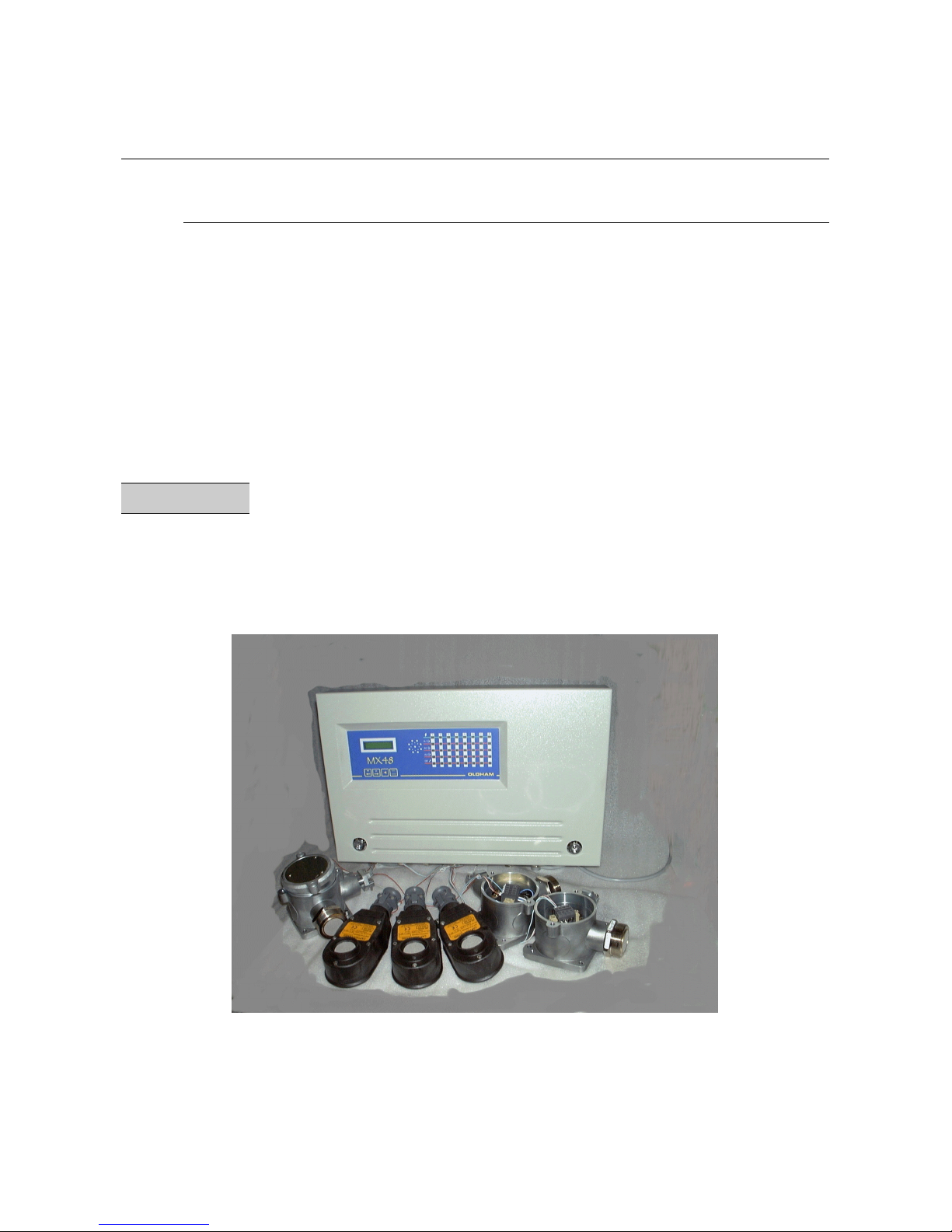
The MX48 measuring and alarm unit can be fitted with between one and 16 independent channels.
Each channel is connected to one or more detectors installed in the locations to be monitored.
The measurement that is output from the detector is displayed on the MX48 unit and compared with
alarm thresholds. If thresholds are exceeded, the unit actuates relays which can be used to control
external devices.
REMARK
The equipment of the MX48 unit comprises 1 or 2 PCBs (option), each equipped with 4 channels.
However, each channel is independent and can be connected to any type of OLDHAM detector
provided that the PCB is suitably programmed.
Page 7

8
MMAAIINN CCHHAARRAACCTTEERRIISSTTIICCSS
• Wall-mounted box (500 x 340 x 89)
• AC or DC power supply
• 4 or 8 measuring inputs for detectors
• Display of measurement on a plasma display panel (2 lines - 16 characters)
• One keypad with four keys on the front panel for the user
• One keypad with four keys for maintenance (on the display unit card, accessible only by
opening the front panel)
• One “CALIBRATION” key and one “PROGRAMMING” key for maintenance (on the
display unit card, accessible only by opening the front panel)
• 3 gas alarms per channel
- Two instantaneous rising or falling thresholds, manual or automatic clearing, with
“extractor control logic (tunnel parking application)”
- One rising or falling threshold, automatic clearing, triggering by time delay or
average
Relaying
Total of 10 or 18 relays distributed as follows:
- Two relays per channel, with positive or negative safety, contacts open or closed
at rest for the first two thresholds
- One relay common to channels for third thresholds or for all alarms (buzzer
transmission), with positive or negative safety, contacts opened or closed at rest
- One relay common to channels for faults and failures, constant positive safety
mode, contacts open or closed at rest.
• Current output (4-20 mA) per measuring channel.
• Common audio alarm that can be acknowledged in the case of occurrence of gas alarms.
Page 8
9
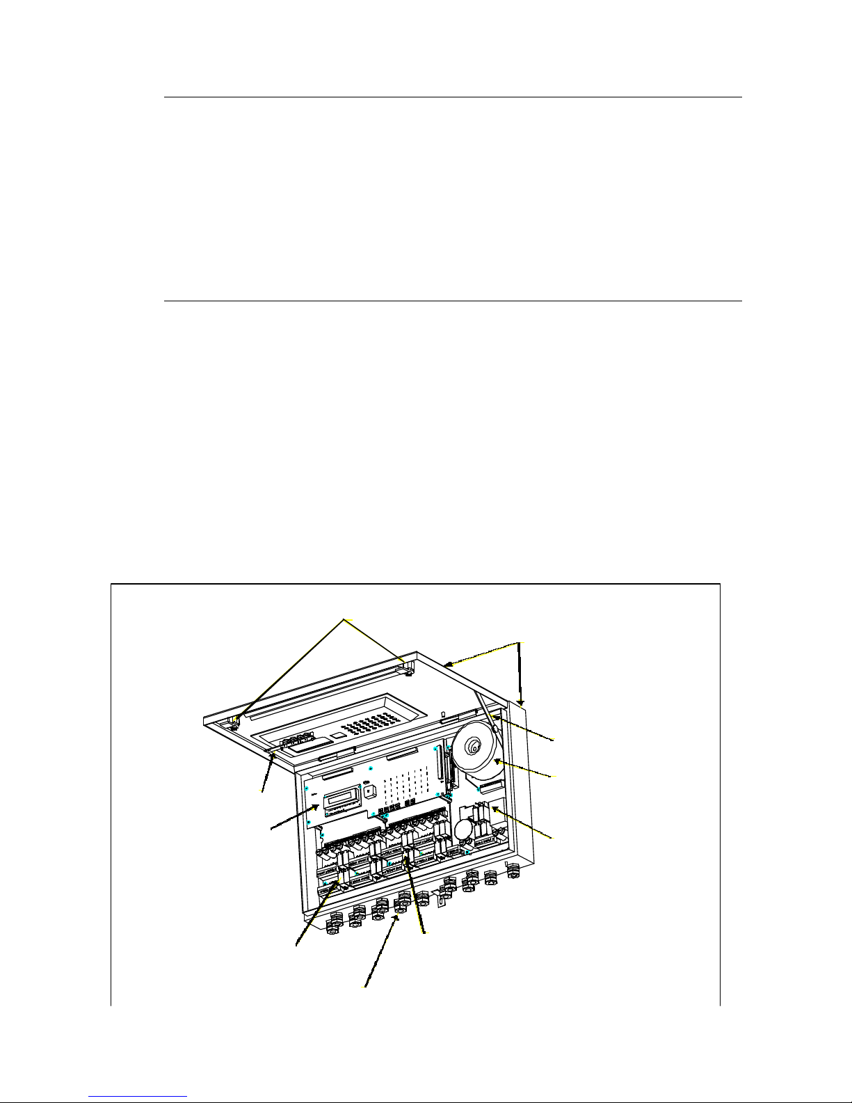
1.2. the wall-mounted box
The housing of the MX48 is a wall-mounted box consisting of a back casin and a cover which can
be pivoted.
• Dimensions: Fig. 1 (end of this manual)
• Overall view, casing open : Fig. 2
1.3. The various printed circuit boards
• Overall view: Fig. 2
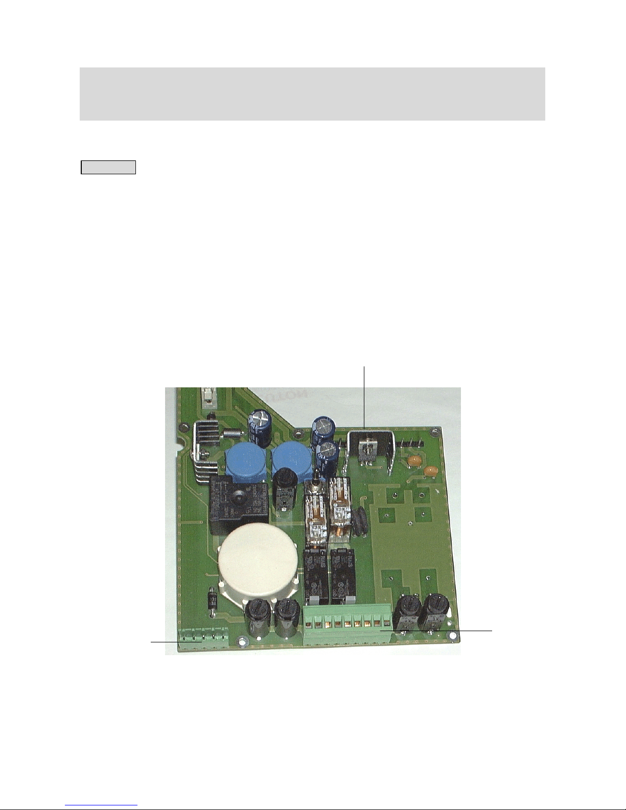
• Power supply board : Fig. 3
• Measuring channel board: Fig. 7
• Front link board : Fig. 4
(Comprising the display, the micro part, the DB9 RS223 and RS485 connector and the
keypads).
FIGURE 2 : COMPLETE SET OF BOARDS
VUE D'ENSEMBLE DU MX48
(carter ouvert)
Figure N°2
(voir fig N°4)
(voir fig N°3)
(voir fig N°7)
(voir fig N°7)
(voir fig N°1)
Transformateur
Coffret MX48
15 presses-étoupes PG9
Carte afficheur
Carte alimentation
2 vérrouillages 1/4 de tour
Clavier déporté
Compas pour retenir
le couvercle en
position haute
Première carte
voie de mesure
Deuxième carte
voie de mesure
MX48 box
(see Fig. n°1)
Stay for holding up the
cover
Transformer
Power supply board
(see fig. N°3)
Second measurement
channel board (see fig. N°7)
OVERALL VIEW OF THE MX48
(casing open)
FIGURE 2
15 PG9 cable glands
First measurement channel
board (see fig. N°7)
Display board
(see fig. N°4)
Offset keypad
¼ turn latches – 2 off
Page 9

10
22..
IINNSSTTAALLLLAATTIIOONN AANNDD CCOONNNNEECCTTIIOONNSS
2.1. Installation: recommendations
The MX48 unit can be installed in any premises without an explosive atmosphere. They should
preferably be placed in a ventilated and monitored location (guardhouse, control room,
instrumentation room, etc.).
Attachment is to be ensured in accordance with the dimensions in Figure 1 (3 attachment points).
REMARK
In order to permit the swivelling front panel of the unit to be opened completely, allowance must be
made for opening by rotation through 90° downwards (see fig 2 – end of this manual)
Before making any connections, the unit should be switched off using the main On/Off switch
below and to the left of the FRONT circuit (see Figures 3 rep A).
2.2. Electrical connections of the MX48 Unit (Fig. 8)
The MX48 unit is equipped with a pulse automatic device which enables to connect 24 V DC
voltage in a lack of 220 V AC voltage so we can use no expansive save power supply.
2.2.1. Alternative power supply
- Voltage: 230 V AC (207 to 244 V) 50/60 Hz
- Maximum power: 200 VA
- Maximum current in cable: 1 A
- Cable: 3 x 1.5 mm² (including earth)
- Location of connection terminal blocks: Fig. 8,
- Protection: the phase and neutral wires are protected by time-delayed 2 A
fuses located at the rear of the power module (fig3).
- Voltage: 103 to 122 V AC - 50/60 Hz on option
CAUTION
It is mandatory that the appliance must be earthed. A terminal is reserved for this purpose at the
back of the power module: see Fig. 5. This connection is required in order to ensure correct
operation of the following:
- mains power interference filter,
- protective devices against electromagnetic interference.
Page 10

11
2.2.2. DC power supply
- Voltage: 21 to 30 V continue. The "-" from continue power supply is linked to
earth (and earth being linked to frame).
- Maximum power: 150 W
- Maximum current in cable: 6.3 A
- Cable: 2 x 2.5 mm²
- Location of terminal block: see Fig. 8, item D
- Protection: by two fuses located at the back of the power module (Fig. 3)
2.3. Detectors (Figure 12)
REMARK
- The detectors are linked by SHIELDED cables.
- The utilization of shielded cables is MANDATORY
- The earth braid of shielded cables must be connected to the earth at one end
only.
CAUTION
Each channel is configured in the factory for a given type of detector (explosive gas, toxic
gas, fire or flame). If two different types of detector are interchanged, this may result in
the destruction of the central unit or of the detector.
2.3.1. Explosimetric detectors of PONT type
Three connecting wires for a shielded cable.
Resistance of detector / unit cable: 16 ohms maximum per wire, i.e. 32 ohms in loop (1 km for cable
3 x 1.5 mm²).
Connection on MX48 unit: see Fig. 10 – Example 1
2.3.2. 3-wire detectors 4-20 mA: 3 connecting wires for shielded cable
- Resistance of detector / unit cable: 16 ohms maximum per wire, i.e. 32 ohms in loop
(1 km for cable 3 x 1.5 mm²).
- Connection on MX48 unit: see Fig. 10. – Example 2
Page 11

12
2.3.3. 2-wire detectors 4-20 mA: 2 connecting wires for shielded cable
- Resistance of detector / unit cable: 32 ohms maximum per wire, i.e. 64 ohms in loop
(2 km for cable 2 x 1.5 mm²).
- Connection on MX48 unit: see Fig. 11. – Example 2
2.3.4. FIRE detectors: 2 connecting wires for shielded cable
The current commercial designations are as follows:
- “Thermovelo” detectors of type EC 11 (sensitive to temperature variations)
- Ionic detectors of type EI 1 100 (sensitive to smoke)
- Optical detectors of type EO 1 100 (sensitive to smoke)
- Resistance of detector / unit cable: 28 ohms maximum per wire, i.e. 56 ohms in loop (2 km for
cable 2 x 1.5 mm²)
- Fire detectors can be detected in parallel to a maximum of five. The end-of-loop resistor
(2.7 K) is to be placed at the end of the line on the last detector.
- Connection on MX48 unit: see Fig. 11. – example 1
2.3.5. FLAME detectors: 2, 3 or 4 connecting wires for shielded cable
depending on utilization
Page 12

13
REMARK
The detectors can be supplied with power either via the MX48 unit or by an auxiliary 24 V DC
source.
These detectors can operate in standalone mode:
24 V DC power supply and direct utilization of relay contacts in accordance with the
technical specification corresponding to the detector used.
The current commercial designations are as follows:
- model 20/20 U - analog - type UV - 752002 (sensitive to UV radiation)
- model 20/20 UC - analog - type UV (sensitive to UV radiation)
- model 20/20 UB - µP technology - type UV - 772002 (sensitive to UV radiation)
- model 20/20 UBC - µP technology - type UV (sensitive to UV radiation)
- model 20/20 LC - analog - type UV/IR (pyroelectric, combination of UV and IR
detectors)
- model 20/20 LBC - µP technology - type UV/IR (pyroelectric, combination of UV and
IR detectors)
- model 20/20 I - µP technology - triple IR detector - 780002 (pyroelectric, sensitive to IR
radiation)
These detectors are equipped with various types of terminal block (see table below).
Model 20/20 U 20/20 UC 20/20 UB 20/20 LC 20/20 UNC 20/20 LBC 20/20 I
Type
of terminal
block
B
C
A
C
C
C
A
- Resistance of cable / unit
- In the case of local 24 V DC power supply:
8.5 ohms maximum per wire, i.e. 17 ohms in loop
- In the case of power supply via the MX48 unit:
3 ohms maximum per wire, i.e. 6 ohms * in loop
∗ 4 ohms for detector 20/20 I (IR3)
- Connection on MX48 unit (ONE detector per measuring channel ONLY):
- detector equipped with a terminal block of type A: see Fig. 13
- detector equipped with a terminal block of type B: see Fig. 14
- detector equipped with a terminal block of type C: see Fig. 15
Example of the utilization of the 4-20 mA signal from flame detectors equipped with connectors of
type A or C: see Fig. 16.
Example of the utilization of detectors equipped with connectors of either type A or type B and with
auxiliary power supply. The auxiliary power supply must be able to supply power to the number of
detectors planned in the measuring loop (see Fig. 17).
Page 13

14
REMARK
In the case of this application, the maximum of five flame detectors can be connected in the
measuring loop.
Example of the utilization of IR3 or UV/IR detectors equipped with connectors of type A with a
local junction box and galvanic insulation (see Fig. 18).
2.3.6. CO2 detector of type “Ventostat VT”
- Connection on MX48 unit: see Fig. 20.
- Resistance of detector/unit power cable: 12 ohms maximum per wire, i.e. 24 ohms in
loop.
- 4-20 mA output: maximum load = 280 ohms (whole loop)
2.3.7. Specific case of intrinsic safety detectors
Two types of intrinsic safety barrier can be used: Z787 / EX and MTL787S+.
PRECAUTIONS
Before connecting the barrier to the unit, check that the voltage is < 25 V DC.
- A short circuit in the electrical connections will result in destruction of the barrier.
- Perform wiring in the DE-ENERGIZED state.
- The electrical link between the MX48 unit and the clipper is made using a screened
cable with two active conductors with a maximum resistance of 12 ohms each.
Page 14

15
REMARK
In classified areas, the installation must comply with the standards in force.
- Connections on MX48 unit: see Fig. 21.
IMPORTANT
All intrinsic safety installations must be APPROVED as a whole assembly by an approved
organization (DRIRE, etc.).
OLDHAM “INTRINSIC SAFETY” BARRIERS
Type of IS
barrier
Reference Specific features OLDHAM box
reference
Z787 / EX 6184703 To be fitted on DIN
RAIL
MTL787S+ 6797100 To be fitted in an
approved box:
MANDATORY
For 2 clippers 6797192
For 5 clippers 6797547
For 12 clippers 6797101
2.3.8. Other detectors with standardized current output
Any detector (with 2 wires or 3 wires) that can be supplied with power between 19 V DC and 32 V
DC and that supplies a standardized current (signal) of between 4 and 20 mA can be connected to
the MX48 unit.
The connection requirements are identical to those for the corresponding OLDHAM detectors (see
Fig. 22).
2.3.9. Parking application
CTX300 "Co parking" toxic gas detectors can be fitted in parallel when a mean gas concentration is
to be obtained. The detectors must, imperatively, be located in the same area. In this case, a
maximum of five detectors can be connected (see Fig. 23).
Page 15

16
2.4. Connecting the unit to external devices
2.4.1. Slaving controls
The 8 measuring channels of the MX48 unit are each equipped with two relays which can be used
to control external devices: sirens, solenoid valves, extractors, telephone calls, etc..
For each measuring channel, the relays are distributed in the following manner (see Fig. 7):
- a relay associated with the triggering of alarm 1 (fig 7),
- a relay associated with the triggering of alarm 2 (fig 7),
- use of open or closed contacts selected with a jumper (see Fig. 7 – item A),
- use of positive or negative safety selected by programming (see the CHANNEL
programming menu),
- contact outputs on the back of the measuring board (see Fig. 12).
- An example of connection is given in Fig. 24:
- a siren connected to relay AL1 will be actuated as soon as alarm 1 is triggered,
- a solenoid valve connected to relay AL2 will be actuated as soon as alarm 2 is
triggered.
For all channels:
- A common relay associated with the triggering of alarm 3 for the 8channels (fig 3).
By programming, this common relay can also be used for the remote transmission of the
audio warning signal. (This relay will then be associated with all the unit’s alarms).
- A fault relay associated with the triggering of channel faults (detector failures, electrical
connections, excessively negative zero, etc.). This relay will always be in positive safety
mode (see Fig. 3).
- The use of open or closed contacts is selected by programming on common board (see
Fig. 3).
- Common relay contact outputs on the back of the power module: Fig. 8.
REMARK
Owing to the breaking capacity of the MX48 unit’s relays which is limited to 2 A / 250 V AC or 30
V DC, external intermediate relays must be used if the devices to be controlled require high power
levels.
The relay contacts are indicated : unit switched off
Page 16

17
2.4.2. 4-20 mA current outputs (Fig. 12)
For each measuring channel, the MX48 unit is equipped with a 4-20 mA output that can be used to
retransmit measurements to a recorder or an external PLC. The maximum resistance in loop mode is
600 ohms. The earth connections for the 4-20 mA outputs are common and the unit. The 4-20 mA
lines are not galvanically insulated one from the other. The current output varies according to the
measurement and has several states, as follows:
- On starting up the unit: I < 1 mA
- With FAULT: I < 1 mA
- In MAINTENANCE mode: I = 2 mA
- ZERO MEASUREMENT: I = 4 mA
- Full scale: I = 20 mA
- Out of range or “in doubt”: I > 23.2 mA
An example of the connection of a multi-channel recorder is given in Fig. 25.
2.4.3. RS 232 and RS 485 outputs
RS232 OUTPUT
A computer can be connected on a female sub.D/DB9 type connector located on the back of the
micro board (fig 4 repA). The MX48 programming, from outside, will be possible thanks to this
connection.
RS 232 OUTPUT USING
- Remove the DB9 connector (plug with an internal strap)
- Connect a link cable ref.6315831 which will link the monitor to the computer on the
MX48 available female connector DB9 (Fig 6)
- when the using is stopped : no connect the cable and put the male DB9 "plug" again.
Female DB9
Male DB9
MX48
PC COMPUTER
Page 17

18
RS 485 OUTPUT (PINABLE ON FIG 8)
Several MX48 units can be linked to a single computer, which is the "master" of the network. In
this case, a "SLAVE NUMBER" (by programming/unit) is asigned to each MX48 unit.
This RS 485 output can be galvanically insulated as an option.
1st case : no galvanic insulation
- no mounted insulation component
- 2 polarization electrical resistances are welded and programmed with J103 and J104 pins
2nd case : with galvanic insulation
- mounted and welded insulation component
- no programmed polarization electrical resistance for "plus" (+ 5V) (J104 programming
pins)
a) with RS 485 shielded
- no programmed polarization resistor for "moins" (GND) (J103 programming
pins)
b) without RS485 shielded
- programmed polarization resistor for "moins" (GND) (J103 programming pins)
End loop resistor
It is located on the MX48 micro board and must be programmed with the last MX48 unit of the
loop (by pins) with a 120 Ohms value.
The MX stored data are some instantaneous values
The RS485 output is a half duplex type.
RS 485 OUTPUT USING
- No change the sub D/DB9 "plug" connector (fig 4 – item A)
- Connect the screwed connector terminals 3, 4 and 5, located on the power supply board
of the MX48 unit. See connection details fig 8.
- Owing to mounted wires or not (following the mounting and the equipment linked or not
on the earth…).
Page 18
19
IMPORTANT
All details regarding the RS 485 complete description (Modbus / Jbus format, structures,
adresses aso…) are developped in a leaflet ref. D 813 577.
CAUTION
A computer or a printer management interface must be used in order to printout the data stored by
the MX48 unit. See details and possibilities in a leaflet ref. 8 813 571.
2.4.4. Remote acknowledgement
It is possible to allow remote acknowledgement by connecting on terminals clear 1 and clear 2 (loop
16 mA), of the connector located on the power supply board : see fig 8.
Maximum load impedance : 1 K
Remark : several MX48 units can be connected to the same remote acknowledgement system
provided that the polarities are respected.
Power supply
terminal
Transformer terminal
Clear and RS485
terminal terminal
Page 19

20
33..
SSTTAARRTTIINNGG UUPP
3.1. Checking the installation
It is checked that, at least, all connections have been made and that the complete installation
complies with current standards in force.
CAUTION
OLDHAM is not responsible for the compliance of the complete electrical safety system.
The MX48 unit is switched on by means of circuit breakers * provided for that purpose and which
ensure protection of the mains power unit.
* The circuit breakers are to be selected according to the power consumption levels specified by the
manufacturer and the length of the electric cables.
3.2. Switching on the unit
CAUTION
The handling operations and adjustments described in these paragraphs are strictly
reserved for authorized personnel as they are liable to affect detection safety.
To start up the MX48 unit, you must:
- swivel the front panel,
- press the ON/OFF button located to the bottom left-hand side of the FRONT
circuit: see Figures 3 (item A).
- The display panel then shows, for example:
MX 48/52 V1.0
The unit then goes into INITIALIZATION mode for one minute. Consequently, all the alarms are
inhibited and the current outputs are 1 mA for the channels in service. The unit then performs a selftest * on its buzzer and all its night-emitting diodes. At the end of this one-minute period, the
channels in service return to normal operation and the corresponding alarms and relays are enabled.
Page 20

21
* The user can carry out a “manual-self test” by pressing the test key at any time (see Fig. 26).
This self-test lasts 20 seconds and the display panel may show the following displays one after the
other, for example:
then
The user can interrupt the self-test cycle before it is completed by pressing the
ACKNOWLEDGEMENT key of the front panel keypad.
3.3. Operating modes
3.3.1. Audio warning device (buzzer)
In normal operation, the audio warning device is triggered whenever a fault or an alarm appears.
The audio warning device can be stopped by pressing the ACKNOWLEDGEMENT key or by
remote acknowledgement. The buzzer makes a continuous or discontinuous sound (according to the
programming of the unit) if an alarm threshold is exceeded.
3.3.2. Light-emitting diodes (LED) (Fig. 1 and fig 4)
Each channel is equipped with five LEDs (visible and identified on the FRONT panel).
LED Extinguished Illuminated
in steady mode
Flashing
GREEN Channel not in
service
Channel in service Threshold AL1 exceeded
(manual clearing) and not
acknowledged
1st red AL1 not triggered Threshold AL1 exceeded
(automatic clearing)
Threshold AL2 exceeded
(manual clearing) and not
acknowledged
2nd red AL2 not triggered Threshold AL2 exceeded
(automatic clearing)
3rd red AL3 not triggered Threshold AL3 exceeded by mean
or time (automatic clearing)
Yellow No fault Fault on channel -Channel being calibrated or
programmed
- Detector being calibrated
MX 48/52 V1.0
xx LEL CH4
*** SELF-TEST ***
xx LEL CH4
Line corresponding to
the channel displayed
when the ENTER key
was pressed
Page 21

22
3.3.3. Alarm thresholds
Each of the three alarm thresholds can be programmed independently for each channel. (See the
“Channel programming” menu).
In normal operation, a gas alarm is only triggered after a preprogrammed time delay in order to
avoid spurious alarms.
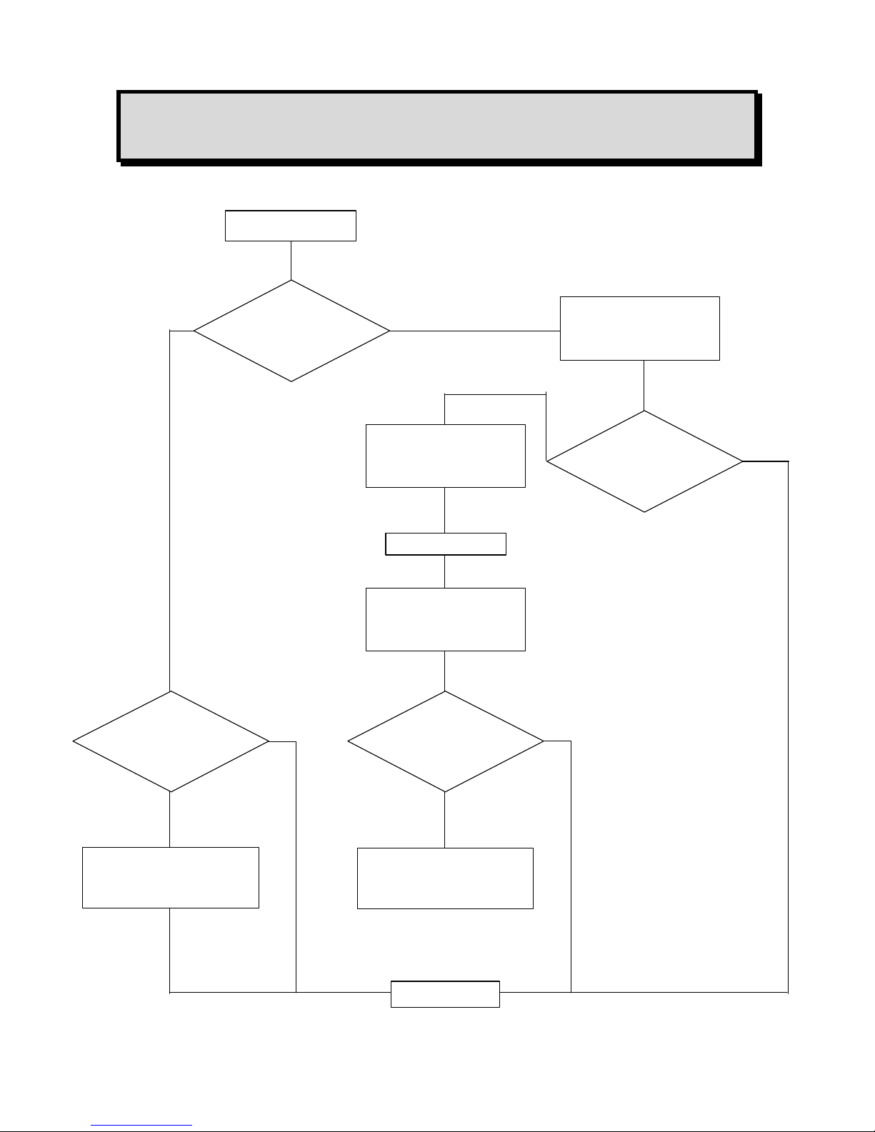
Alarm thresholds can be processed in the following manners:
- in normal cycle with manual clearing: block diagram 1,
- in normal cycle with automatic clearing: block diagram 2,
- in parking cycle: block diagram 3.
The alarm thresholds are to be selected according to the gases detected and the corresponding
standards in force.
Special case: A channel connected to a fire detector
- It is MANDATORY to select the scale with 100 divisions.
- It is MANDATORY to select the alarm threshold with 60 divisions.
(Owing to the end-of-loop resistor of 2.7 kΩ, the fire detector outputs 4 mA when no fire is detected
and 20 mA if a fire is detected).
Page 22
23
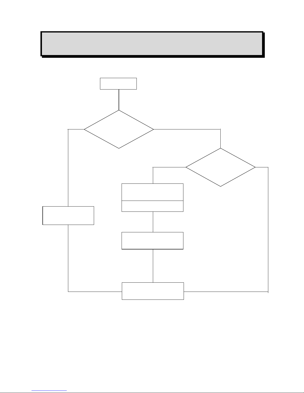
BLOCK DIAGRAM 1
NORMAL CYCLE WITH MANUAL CLEARING
Alarm
acknowledged
LED extinguished
Relay disengaged
Buzzer stopped
No
Illumination of flashing
alarm LED
After T2 time
START
Threshold
exceeded
Time T1
exceeded
Illumination of flashing
alarm LED
LED steady mode
Buzzer stopped
END
Relay engaged
Buzzer engaged
No
No
No
Yes
Yes
Yes
Yes
Alarm
acknowledged
Page 23
24
BLOCK DIAGRAM 2
NORMAL CYCLE WITH AUTOMATIC CLEARING
START
Threshold
exceeded
Time T1
exceeded
LED extinguished
Relay disengaged
Alarm LED illuminated
in steady mode
After T2 time
Relay engaged
Buzzer engaged
END
Yes
No
No
Yes
Page 24
25
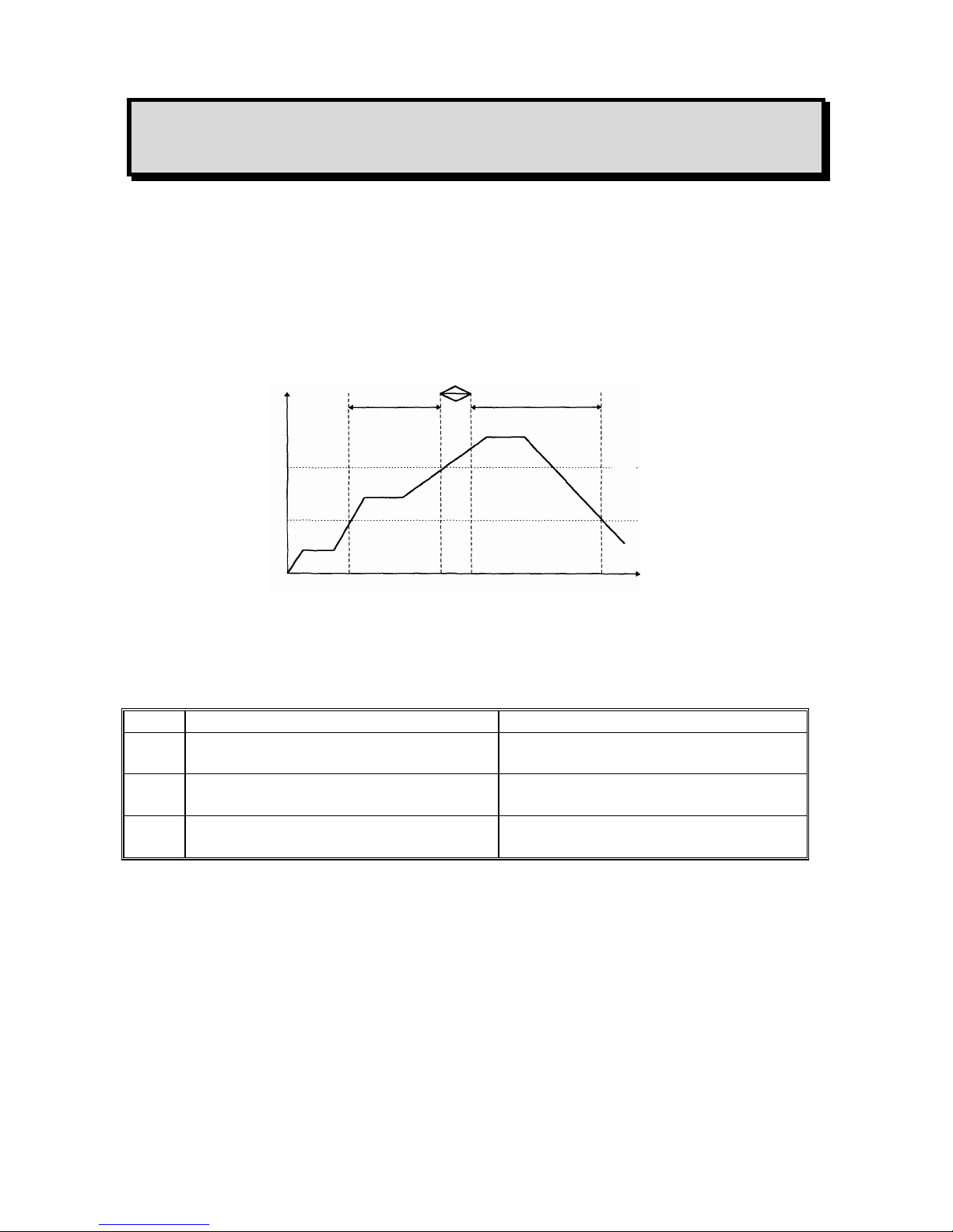
BLOCK DIAGRAM 3
PARKING CYCLE
Alarm 3 operates in the same way as the normal cycle.
The times defined for alarms 1 and 2 (time delays) are, in this case, used to define the minimum
operating time for each relay.
t AL1 tR1 R2 t AL2
Threshold AL2
Threshold AL1
Starting of
relay R1
Stopping
of relay R1
Starting of
relay R2
Stopping of
relay R2
min.
t
AL1
Min. operating time for alarm 1
(defined for each channel)
t1
t
AL2
Min. operating time for alarm 2
(defined for each channel)
t2
t
R1 R2
Switching time from relay 1 to relay 2
(defined for the whole unit)
t
R1 & R2
Page 25

26
3.3.4. Fault thresholds
Processing of detector faults
Each channel detects the following faults.
For toxic and explosive gas detectors:
- line interrupted (0 mA),
- line short-circuited or excessive consumption,
- negative offset (more than 20% of measuring scale),
- line in calibration mode (2 mA) (if confirmed by programming).
For detectors of the explosive gas type (4-20 mA and 340 mA) in normal mode and if the
measurement is greater than 100% of the measuring scale, there are the following immediate
results:
- Display: SUP
- The relays are actuated if the thresholds are reached.
- The general fault relay is actuated.
- The 4-20 mA output of the channel is greater than 20 mA.
- All these states are memorized and the only way of acknowledging them is to
switch off the channel and then restart it.
Faults are valid after a preprogrammed time (in the same way as alarms).
FAULT BLOCK DIAGRAM
END
START
Wait until the fault has been present
for at least 5 seconds.
The relays are locked in their current state.
The common fault relay is engaged.
The buzzer is engaged.
The channel fault LED is illuminated. *
1 mA is sent on the 4-20 mA output.
* The LED is extinguished as soon a the fault disappears.
Page 26

27
3.3.5. Measuring unit
One minute after starting up, and if no test action is performed on the keypad, the unit successively
scans all the channels in service and displays the measured values.
Examples of display
OR
- Each channel is interrogated for 10 seconds.
- The user can interrogate a channel manually by selecting that channel with the + and -
keys to obtain a manual display for one minute.
- The user can return to normal cyclic scanning during that one-minute period by
simultaneously pressing the + and - keys. The display panel then shows alternating
displays, three times in succession:
For example:
then
Channel 1
x x LEL CH4
Channel 2
x x x ppm CO
Channel 5
x x x ppm CO
normal scan
x x x ppm CO
Page 27

28
44.. UUTTIILLIIZZAATTIIOONN
4.1. List and functions of the various items of “USER” equipment for
programming and calibration of the unit
4.1.1. Keypads
The first is equipped with four touch keys accessible without opening and swivelling the MX48
unit’s FRONT panel, the second is equipped with the same keys accessible by opening and
swivelling the FRONT panel for maintenance (Fig 4 rep B).
NORMAL MODE
- Manual display of previous channel
- Combined with the “PLUS” key to restart the channels
automatic display cycle.
MAINTENANCE MODE
- Manual display of previous channel
- Decrease value, threshold, etc.
- Display of previous choice (oná off, etc.)
- NO
NORMAL MODE
- Manual display of next channel
- Combined with the “MINUS” key to restart the
channels automatic display cycle.
MAINTENANCE MODE
- Manual display of next menu
- Increase value, threshold, etc
- Display of next chooice (oná off, etc)
- YES
Page 28

29
- “Audio and visual” or “audio” clearing of an alarm
- Exit from a current menu
- Start a self-test manually
- VALIDATE
4.1.2. Maintenance keys
PROGRAMMING key (Fig 4 item D): accessible after opening and swivelling the front panel.
- Combined with the “-” key to go back in a menu.
- To quit normal display mode and access the various menus (see block diagram of
the various menus).
- To scroll through a menu.
CALIBRATION key (Fig 4 item C) : accessible after opening and swivelling the front panel.
- To set a channel to CALIBRATION mode.
- To quit that mode.
4.1.3. Potentiometers
Each measuring channel has 5 potentiometers. These are accessible by opening and swivelling the
FRONT panel of the MX48 unit and are laid out as follows (see Fig. 5):
1 detector ZERO potentiometer
1 detector sensitivity potentiometer
1 potentiometer 4 mA / current output
1 potentiometer 20 mA / current output (for full scale)
1 potentiometer filaments power supply (340 mA)
Page 29

30
4.2. Menus
4.2.1. The various menus and their functions
The MX48 unit has five menus that are accessed by pressing the “Programming” key (item D, Fig.
4).
These five menus are as follows:
DESIGNATION FUNCTION
“CHANNEL” programming - To program the whole configuration of a measuring
channel (ON/OFF, range, alarm thresholds, etc.)
“SIMULATION” programming - To artificially vary a channel measurement on:
- the display panel,
- the 4-20 mA current output.
- To trigger the alarms (LED and relays) at the same
time.
“CHANNEL COPY” programming - To copy the complete programming from one channel
to another (time saving)
“UNIT” programming - To program the whole configuration of the MX48 unit
(language, slave number, etc.).
“UPLOADING” programming Do not use this mode (re-programming of the MX48
unit).
4.2.2. Block diagram of the scrolling of the various menus
It is easy to use these various menus by means of the keys on the keypad and the “Programming”
key (Fig 4).
Detailed flow diagrams of the menu scrolling function and of each menu are given on the following
pages.
Page 30

31
SCROLLING OF THE VARIOUS MENUS
NORMAL
DISPLAY
P
Programming
[Channel x x]
+
-
Programming
Simulation
+
-
Programming
Channel xx copy
+
-
Programming
Unit
+
-
Programming
Uploading
REMINDER
P
Programming key
+
Keys used to move
-
Page 31

32
4.2.3. Detailed flow diagrams of each menu
CHANNEL PROGRAMMING
Remove on the programming socket before entering into programming
: last channel displayed
: Off On
+
←
→
-
then ENTER
: CHOICE OF RANGES
10 30 100 300 1000 2000 xxxxU
+→+→+→+→+→+
then
ENTER
: SELECTION OF POINT POSITIONING
100 10.0 1.00 0.100 0.010 0.001
+
→+→+ →+ →
+
then
ENTER
: 0 to 2000
+
←
→
-
then ENTER
: 0 to 2000
+
←
→
-
then ENTER
Seuil Alarme 1
[25]
Measuring range
[100..]
Programming
[Channel xx]
Alarm 1 threshold
[25]
NORMAL
DISPLAY
Channel xx
[Off]
Alarm 2 threshold
[50.]
Decimal point
[1...]
P
P
P
P
P
P
Page 32

33
: 0 to 2000
+
←
→
-
then ENTER
: Increasing Decreasing
-
←
→
+
then ENTER
: Increasing Decreasing
-
←
→
+
then ENTER
: Increasing Decreasing
-
←
→
+
then ENTER
: Normal Parking
-
←
→
+
then ENTER
Cycle
[Normal]
P
Alarm 2
[Increasing]
Alarm 3 threshold
[75]
Alarm 1
[Increasing]
Alarm 3
[Increasing]
P
P
P
P
P
Page 33

34
: Manual Automatic
-
←
→
+
then ENTER
: Manual Automatic
-
←
→
+
then ENTER
: Time delay Mean
-
←
→
+
then ENTER
: Negative Positive
-
←
→
+
then ENTER
Alarm 3
[Time delay]
Ack alarm 1
[Manual]
Ack alarm 2
[Manual]
Relay 1 safety
[Negative]
P
P
P
P
Page 34

35
Negative Positive
-
←
→
+
then
ENTER
Free Set to 0 Set to 1
-
←
→
+
←
→
+
then
ENTER
Free Set to 0 Set to 1
-
←
→
+
←
→
+
then
ENTER
Free Set to 0 Set to 1
-
←
→
+
←
→
+
then
ENTER
Free Set to 0 Set to 1
-
←
→
+
←
→
+
then
ENTER
Relai 2
[Free]
Relay 2 safety
[Negative]
Relay 1
[Free]
Relay 3
[Free]
Fault relay
[Free]
P
P
P
P
Page 35

36
The MX48 unit can detect and indicatez (with a flashing
yellow LED) that a line has-been placed in
CALIBRATION mode on the detector.
No Yes
-
←
→
+
then
ENTER
Free display: A channel heading can be programmed
(in 13 characters maximum). By default, the channel
number is displayed in this area.
+
←
→
-
then
ENTER
CH4 CO 2S etc.
-
←
→
+
←
→
+
then
ENTER
LEL % ppm etc.
-
←
→
+
←
→
+
then
ENTER
Time: Time interval between the triggering of the AL
LED and of the corresponding relay, or the minimum
operating time of the relay in parking mode.
-
←
→
+
then
ENTER
Display of time by using keys
-
←
→
+
then
ENTER
Texte
-
←
→
+
then
ENTER
Gas
[CH4]
Cal detection
[No]
Channel xx
[Premises 1 channel] U
Units
[LEL]
Alarm 2 time
[00:00:00]
Alarm 1 time
[00:00:00]
P
P
P
P
P
P
Alarm 3 time
[00:00:00]
P
P
H mn sec
H mn sec
H mn sec
flashing
Page 36

37
(Bridge) (4-20 mA)
(1)
(Fire)
(2)
: Explosive Toxic Spec. tox.
-
←
→
+
←
→
+
then
ENTER
(1) in case of "Up" fault : 3 "gas" alarms and fault alarm are triggered.
(2) In case of "Up" fault : only the fault alarm is triggered.
This key can also be used to exit from the current menu.
-
When in a menu, you can go back (to make checks or modifications,
etc.) by pressing and holding Programming key and by successively
pressing and releasing the down key- .
[ ]
Parameters specified in square brackets [ ] are the VALID parameters
(in memory).
(1) Free This means that the relay can be activated when programming alarm
thresholds are triggered.
Set to 0
This means that the relay is not powered supply, and will not be
activated by MX48 control unit with alarm..
Set to 1 This means that the relay is always powered supply (by the MX48
control unit), and neither will not be activated by MX48 control unit
with alarm. Using of relays will be directly programmed by J-BUS
input and "COM52" software.
Detector type
[Explosive]
End of menu
P
P
INFORMATION
Page 37

38
LIST OF UNITS
DESIGNATION MEANING
LEL Lower explosive limit
% Percent
ppm parts per million
ppb parts per billion
UEG Unter Explosion Grenze (= LEL in German)
LEL Limite inférieure d’explosivité (= LEL in
French)
bar unit of pressure
mb unit of pressure (millibar)
Rh relative humidity
m/s metres per second
mg unit of weight (milligram)
unit + flashing U free indication of unit
-
←
→
+
then
ENTER
Page 38

39
LIST OF GASES
DESIGNATION MEANING
CH4 Methane
CO Carbon monoxide
H2S Hydrogen sulphide
N Nitrogen
NO Nitric oxide
NO2 Nitrogen dioxide
SO2 Sulphur dioxide
CI2 Chlorine
H2 Hydrogen
HCL Hydrochloric acid
HCN Hydrocyanic acid
NH3 Ammonia
ETO Ethylene oxide
PH3 Phosphine
HF Hydrofluoric acid
CFC Freons
CO2 Carbon dioxide
ASH Arsine
SiH4 Silane
BUT Butane
PRO Propane
GNT Natural gas
ETY Ethylene
PNT Pentane
HEX Hexane
PRY Propylene
ACY Acetylene
ETA Ethanol
ACO Acetone
OPR Propylene oxide
OET Ethylene oxide
ISB Isobutane
DIM Dichloromethane
AET Ethyl alcohol
BUN 2-Butanol
ISP Isopropanol
XYL Xylene
TOL Toluene
ESS Petrol (gasoline)
BUD Butadiene
HYD Hydrogen
Gas + flashing U Free indication of name of gas:
-
←
→
+
then
ENTER
Page 39

40
SIMULATION PROGRAMMING MENU
Simulation on previously displayed and
[validated] channel
Free labelled area
S = flashing to indicate that this channel is in
simulation mode.
To artificially vary measurement on the display
panel, on the 4-20 mA output, and trigger alarms
(LED and relays)
= ESCAPE (ECHAPPE)
To exit from this menu and return to normal
operation
Programming
[Simulation xx]
NORMAL
DISPLAY
P
P
Channel xx
LEL CH4 S
Programming
[Simulation xx]
ACK
ENTER
+
-
←
→
+
END OF MENU
Page 40

41
COPY PROGRAMMING
Last channel displayed
Validation of menu
Validation of channel to be copied
: Copy the channel’s configuration to
another channel
xx = indication of “Other channel
number” using keys
-
←
→
+
: Validation of copy
Programming
Copy channel xx
NORMAL
DISPLAY
P
P
Copy channel
[Channel xx => xx]
Programming
[Copy channel xx]
Copy channel
[Channel xx => xx]
ENTER
+ +
ENTER
END OF MENU
Page 41

42
UNIT PROGRAMMING
Validation of menu
Choice of languages:
: French English German Spanish
+
→+→
+
then
ENTER
Choice of transmission speed with
computer:
1200 2400 4800 9600 19200 Bauds
+→+→+→+
then
ENTER
Choice of slave address (this unit)
0 to 250
+
→
then
ENTER
NORMAL
DISPLAY
P
P
+ + +
Programming
Unit
P
P
P
Language
[French]
Programming
[Unit]
Speed
[9600••]
Slave address
[1]
ENTER
Page 42

43
This is the time interval between exceeding of the
AL threshold and triggering of the corresponding
visual alarm (LED).
Display the time using keys:
-
←
→
+
→ then
ENTER
In “Parking” mode: this is the time interval between
stopping of relay 1 and starting up of relay 2.
Display the time using keys:
-
←
→
+
→ then
ENTER
Negative Positive
-
←
→
+
→ then
ENTER
Control of relay 3 (common) by any triggering of
buzzer
NO YES
-
←
→
+
→ then
ENTER
Utilization of common audio alarm (buzzer)?
(Function in series with buzzer jumper)
NO YES
-
←
→
+
→ then
ENTER
YES = If copy of buzzer on alarm 3 and with buzzer
option into service : audible alarm will be triggered
when there is an alarm.
NO = The common audible alarm (buzzer) will be
triggered for a 30 seconds maximum time (even
there is an alarm).
-
←
→
+
→ then
ENTER
Response time
[00 : 00 : 00]
P
P
P
P
P
Relay safety
[Negative]
Relay 1&2 stop T
[00: 00 : 00]
Buzzer transferred
[NO]
Buzzer connected
[NO]
Continuous buzzer
[NO]
END OF MENU
H mn sec
H mn sec
Page 43

44
UPLOADING PROGRAMMING
Only OLDHAM personnel and personnel approved by OLDHAM can be made this operation.
Display of menu
Validation of utilization of
menu
Display of menu
confirmation
Data transfer request
Validation of data transfers
Confirmation of uploading
Programming
Uploading
P
END OF MENU
Uploading
Confirm
Programming
[Uploading]
Uploading
[Confirm]
ENTER
ENTER
NORMAL
DISPLAY
P
+ + + +
Page 44

45
55.. SSEETTTTIINNGG TTHHEE MMXX4488 UUNNIITT IINNTTOO SSEERRVVIICCEE
REMINDER
The handling operations and adjustments described in this chapter must be performed by
authorized personnel only, as they are liable to affect detection safety.
Once the measuring unit has been switched on, it can be programmed (1), its measuring channels
can be programmed (1) according to the detectors used and calibrations can be made on the unit and
detectors.
(1) These programming operations can be carried out directly on the MX48 unit in accordance with
the following procedures or using a computer equipped with the “com 52” software.
5.1. Programming the unit
To program the MX48 measuring unit, and according to the required specifications, the “Unit
programming” menu must be used (see Section IV-2 on Menus) by means of the keypad and the
“Programming” key. Then, the instructions in the menu should simply be followed.
CAUTION
If the unit remains in programming mode for more than 30 minutes, it automatically switches to
fault mode.
5.2. Programming the measuring channels
5.2.1. Programming
To program each measuring channel according to the type of detector used and the required
specifications, the “Channel programming” menu must be used (see Section IV-2 on Menus) by
means of the keypad and the “Programming” key. Then, the menu instructions sho uld simply be
followed.
REMARK
When a channel is switched on, all its relays are in “off” mode and its current output is 1 mA. Then,
one minute later, the channel comes into effective operation (relays ready and output of 4-20 mA).
CAUTION
If a channel remains in programming mode for more than 30 minutes, it is automatically switched
to fault mode.
Page 45

46
5.2.2. Copy
In order to make the programming of ALL CHANNELS less TIME-CONSUMING when the same
programming is required for a number of channels, it is recommended that the “COPY” menu
should be used (see Section IV-2 on Menus) by means of the keypad and the “Programming” key.
Then, the instructions in this menu should simply be followed.
5.3. Calibrations
When it is first switched on, with the unit and measuring cha nnels programmed, CALIBRATING
operations must be carried out on the UNIT and the DETECTORS.
Case 1
Measuring channel connected to a detector with no integrated electronics (explosive gas
detector, CAPTEX, CEX800, CEX810, etc.).
• Prepare the detector for calibration:
- Calibration consists in adjusting the detector ZERO in PURE AIR and its sensitivity to
the STANDARD GAS.
- If the detector zero is set with natural diffusion in pure air, the surrounding atmosphere
must be calm (wind speed of less than 1 m/s).
REMARK
The authorized wind speed is increased to 4.1 m/s when the detector is fitted with a weather
protective device.
• Prepare the measuring channel for calibration:
- Open and swivel the front panel of the MX48 unit.
- Manually set the channel to be calculated using keys + and - on the MX48 keypad
(item B, Fig. 4).
- Press the CALIBRATION key (item D, Fig. 4).
- At the bottom right-hand side of the display panel, the letter C flashes and the yellow
LED for the relevant channel flashes, indicating that the measuring channel is in the
“CALIBRATION” position.
REMARK
When a measuring channel is in the CALIBRATION position, all the alarm relays are inhibited (in
order to avoid interfering with the slaving control networks) and the corresponding current output is
maintained at 2 mA.
- Turn the sensitivity potentiometer five times in the clockwise direction (using a
screwdriver).
- Adjust the DETECTOR ZERO.
Page 46

47
NOTE
If the ambient air is not pure, inject air using a “synthetic air” cylinder and the gas injection pipe or
a remote calibrating fixed device with a flow rate of 60 litres per hour for 25 seconds directly on the
detector or a flow rate of 170 litres per hour for 1 min 45 s using a remote calibrating fixed device.
As soon as the signal is stable on the MX48 display panel, adjust the “MEASUREMENT ZERO”
by adjusting the ZERO potentiometer (Fig. 5) and corresponding to channel to be set up, so as to
read ZERO on the MX48 display panel.
• Adjust the detector sensitivity:
- Inject the calibration gas using the gas injection pipe (or a remote calibrating fixed
device) in the same conditions as those applicable for the synthetic air (zero adjustment).
When the measurement has stabilized, set the value corresponding to the reference gas
concentration on the display panel of the MX48 unit by adjusting the sensitivity potentiometer for
the relevant channel (Fig. 5).
NOTE
For this category of explosive gas detectors, the unit’s display panel indicates 100 DIVISIONS for
100 LEL of an explosive gas.
Example:
If the reference gas is a 2.5% methane concentration, i.e. 50% LEL of methane, adjust to obtain a
display of 50 DIVISIONS.
Formula:
Maximum scale
100 DIV x n% LEL of standard gas
Number of divisions to be set =
100% LEL
Maximum LEL
- Stop the injection of the standard gas, wait for the measurement to return to zero (on the
MX48 display panel). Then, press the "CALIBRATION" key (item C, Fig 4). The
flashing yellow LED is extinguished and the "C" on the display panel disappears. The
measuring channel now operates normally an calibration has been completed.
Page 47

48
Case 2
Measuring channel connected to a detector with no integrated electronics and supplying a
standardized 4-20 mA current. (CTX50, CTX100, CTX200, CTX870, etc.).
• Prepare the detector for calibration:
- See the remarks for zero adjustment in pure air and natural diffusion as in case 1.
- These types of detector (4-20 mA) often have a “CALIBRATION” position (CTX870,
CTX100, etc.) or a calibration menu (CTX2042, COX2040, etc.).
This position has the effect of transmitting a 2 mA current from the detector to the
measuring unit.
- This prevents the triggering of alarms (and slaving controls) during calibrating
operations.
CAUTION
If the detector and the measuring channel are calibrated at the same time, the detector
must be left in normal operating mode but the MX48 unit must be set to calibration mode
in order to inhibit the relays.
⇒ Consult the technical manual for the detector concerned.
- Open the detector (with integrated electronics) in order to gain access to the 4 mA
adjustment and sensitivity (20 mA) potentiometers and to the terminals used to check its
4-20 mA output current.
- With these types of detector, there are two ways of checking the current supplied to the
unit:
o by direct reading on the local display panel (internal to the detector)
o by measurement of current on the terminals provided for that purpose (see the
manual for the detector concerned).
- Prepare the measuring channel for calibration:
- same operations as in case 1.
• Adjust the detector zero.
NOTE
If the ambient air is not pure, inject air using a “synthetic air” cylinder and the gas injection pipe or
a remote calibrating fixed device with a flow rate of 60 litres per hour for 25 seconds directly on the
detector or a flow rate of 170 litres per hour for 1 min 45 s using a remote calibrating fixed device.
As soon as the signal is stable on the local display panel on the detector or with regard to the current
output (4-20 mA), adjust the DETECTOR ZERO by adjusting the detector internal ZERO
potentiometer (see the manual for the detector concerned).
Then, CONSECUTIVELY, adjust the measurement zero by acting on the ZERO potentiometer for
the measuring channel (Fig. 5) so as to read ZERO on the MX48 display panel.
Page 48

49
• Adjust the detector sensitivity:
- Inject the calibration gas using the gas injection pipe (or a remote calibrating fixed
device) in the same conditions as those applicable for the synthetic air (zero adjustment).
When the measurement has stabilized (on the local display panel or on the detector internal
terminals (current measurement)), act on the detector’s internal sensitivity potentiometer (see the
manual for the detector concerned) in order to set the value (on the detector display panel)
corresponding to the concentration of the reference gas or the corresponding current (terminals).
(See the note and examples for case 1).
- Then, CONSECUTIVELY set the value of the standard gas on the MX48 display panel
by acting on the measuring channel sensitivity potentiometer (Fig. 5).
- Stop the injection of the standard gas, wait for the measurement to return to zero (on the
MX48 display panel). Then, press the “CALIBRATION” key (item C, Fig. 4). The
flashing yellow LED is extinguished and the “C” on the display panel disappears. The
measuring channel now operates normally and calibration has been completed.
5.4. 4-20 mA output adjustment for a measurement channel
Ø 4 mA adjustment
- for a zero display
- check1 the 4 mA output current and adjust it if necessary using the 4 mA
potentiometer : see fig 9.
Ø 20 mA output adjustment
- following the measurement display and the following formula :
Maximum scale
I = 4mA (0-DIV) + 16 mA x Number of divisions set
100 DIVISIONS
- Check1 the 4 mA output current and adjust it if necessary using the 20 mA
potentiometer : see fig 9
1
Current reading is possible by connecting directly the corresponding output current (see fig 12) a "continuous"
milliammeter.
Page 49

50
66.. MMAAIINNTTEENNAANNCCEE
REMINDER
The handling operations and adjustments described in this chapter must be performed by
authorized personnel only, as they are liable to affect detection safety.
6.1. Periodic / preventive maintenance
6.1.1. On the MX48 unit
The MX48 measuring unit requires practically no surveillance. It is, however, recommended that
the facilities available on the MX48 unit should be used to regularly test the appliance’s essential
functions, as follows:
Use the TEST key to check the correct operation of all the LEDs and the buzzer.
Use the “SIMULATION” menu to check the correct operation of the display panel, the triggering of
alarms (LED and relays), the slaving controls and the 4-20 mA current output.
Cause a fault to occur (such as a line fault by disconnecting a detector wire) to check the correct
operation of the fault “stages”.
6.1.2. On the detectors
The detectors must be calibrated at least twice a year.
Case 1
Detectors without integrated electronics (CAPTEX, CEX800, CEX810, etc.)
With this type of detector, the zero and sensitivity adjustments must be made on the MX48 unit.
SEE THE CHAPTER ON CALIBRATIONS (see 5-3, case 1) and carry out the operations
specified.
Case 2
Detectors with integrated electronics (CTX50, CTX100, CTX870, etc.)
With this type of detector, and for periodic maintenance, all that is required is action on the
detector. SEE THE CHAPTER ON CALIBRATIONS (see 5-3, case 2) and carry out the operations
specified.
Page 50

51
NOTE
Our company is at your disposal to supply you with standard gas or an annual surveillance contract
(preventive maintenance). Under this contract, our specialists guarantee the perfect operation of
your installation. No adjustment is to be made between OLDHAM servicing operations. This avoids
any additional workload for the user’s maintenance services.
6.2. Failures: causes and remedies
FAILURES CAUSES REMEDIES
Display channel not lit up and
no indicator light on.
On/Off switch in the Off
position.
Set the switch to the On
position (item A, Fig. 26).
Problem with mains power
supply or DC power supply
(24 V DC).
Check the supply voltages on
input to the MX48 unit and, if
necessary, check in the
electric power supply
cabinets.
Mains fuses blown. Replace the mains fuses (see
item A, Fig. 5).
DC power (24 V DC) input
fuses blown.
Replace the 24 V DC fuses
located at the back of the
MX48 unit (item B, Fig. 5).
+24 V DC internal protection
fuse blown.
Replace the +24 V DC fuse
located on the power board
(item C, Fig. 5).
CAUTION
When replacing a fuse, it is mandatory to comply with the
required type and rating.
Fault indicator light on (in
steady mode).
Faulty electrical connections
on the telemetry line (wires
and detector).
Check the connections on the
MX48 terminal block and the
detector terminal block.
Check that there is no short
circuit or break in the wires
on the telemetry cable.
Faulty detector. Repair or replace the detector
(see internal electronics or
cell).
The type of detector does not
match the measuring channel
configuration.
Connect the correct type of
detector with the
corresponding measuring
channel.
CAUTION
The measuring channel or line
may be damaged.
Negative offset too great
(more than 20% of measuring
scale).
Perform calibration on the
detector and, then, on the unit,
if necessary. If the problem
persists, the cell must be
replaced.
Page 51

52
Channel in maintenance mode
for more than 30 minutes.
Return the channel to normal
operation by pressing the
Calibration key (Item C, Fig.
4).
Fault indicator light on (in
steady mode) and SUP
displayed.
The measurement is higher
than 100% of the measuring
scale.
To acknowledge the alarm,
the measuring channel must
be switched off and then
switched on again (by
programming).
If the problem persists and the
measurement is not consistent
with reality, the detector must
be calibrated.
An LED does not light up even
though the corresponding
threshold is exceeded and the
buzzer and relay are actuated.
Faulty LED. Perform a general test on the
LEDs by pressing the TEST
key on the keypad and, if the
LED still does not light up,
the programming must be
modified by using the “Unit
programming” menu (buzzer
connected?).
An alarm is triggered, the LED
lights up and the relay is
actuated but there is no audio
alarm.
The buzzer strap is not
correctly positioned.
Fall the buzzer switch
(Fig. 4).
The buzzer is not programmed
as “in service”.
If the audio alarm is wanted,
the programming must be
modified by using the “unit
programming” menu (buzzer
connected?).
The audio alarm stops after 30
s although alarms are still
actuated.
The buzzer is programmed to
operate for 30 seconds only.
If the buzzer is to be sounded
as long as the alarms are
actuated, the programming
must be modified by using the
“Unit programming menu”
(continuous buzzer?).
An alarm is triggered but the
slaving controls are not
actuated.
The relays are faulty.
Short-circuit or open the relay
contact (as applicable) on the
MX48 terminal block (Fig.
12) and, if the slaving
controls operate normally, the
corresponding channel board
must be repaired by an
approved technician.
Page 52

53
Faulty electrical connections. Short-circuit or open the relay
contact (as applicable) on the
MX48 terminal block (Fig. 12)
and, if the slaving controls still
do not work, the connections
must be checked on the MX48
connector and on the slaving
systems.
An electronic detector is in the
“CALIBRATION” position
and the corresponding channel
of the MX48 unit remains in
normal operation: no flashing
yellow LED.
The channel is not
programmed to detect a
detector in “Calibration”
mode.
If it is so wished, the
programming of this channel
can be modified by using the
“Channel programming” menu
(self-calibration) and choose
"CAL detection : YES".
Impossible to upload data from
the MX48 to a computer.
Faulty electric connections. Check the connections on the
MX48 unit connector (Fig.8)
and the computer. Check that
the cable is satisfactory.
The cable does not match the
2-wire RS485 type of link.
Replace the cable with a
suitable one.
Remote acknowledgement is
impossible.
Faulty electric connections. Check the connections on the
MX48 unit connector (Fig. 8)
and on the punch-type button.
The punch-type button is
faulty.
Replace the punch-type button.
6.2.1. Data printing
EXAMPLE
CAUTION
A computer or a printer management interface must, imperatively, be used to print data.
Computer
MX48
COMPUTER INTERFACE
COMPUTER INTERFACE
Printer
Page 53

54
6.3. List of spare and replacement parts
DESIGNATION REFERENCE
Complete power unit 6451451
Complete measuring four channels board 6451552
Complete main board (FRONT)
(micro+display)
6451450
Female connector (5 points) 6152857
Line Female connector (9 points) 6152877
“Measuring channel” fuse, 630 mA, time-
delayed
6154627
DC power supply fuse, 12.5 A, time-delayed 6154624
AC power supply fuse, 6.3 A, time-delayed 6154700
Fuse, 125 mA, time-delayed 6154701
Power board relay (DC) 6155745
Common alarm relay 6155752
AC mains relay (110 V AC) 6155761
“Measuring channel” alarm relay 6155752
“Channel actuating” relay 6155744
Lithium battery (on micro board) 6111174
Buzzer 6112214
Toroidal transformer 6111201
Fluorescent display panel 6133521
On/Off switch 6153436
Maintenance screwdriver 6145845
Complete casing MX48 6121547
Complete keyboard (FRONT) 6451453
CAUTION
It is mandatory that replacement parts must be guaranteed OLDHAM S.A. original parts
as, if this is not the case, the safety of the equipment could be affected.
Page 54

55
77.. DDEETTAAIILLEEDD TTEECCHHNNIICCAALL CCHHAARRAACCTTEERRIISSTTIICCSS
MANUFACTURER
OLDHAM
62000 ARRAS - FRANCE
BOX
- Wall-mounted box dimensions : 500 x 340 x 89
- Function: measuring unit
- Capacity: 4 or 16 measuring channel
- Measurement: continuous
- Storage temperature: -20°C to +55°C
- Operating temperature: -10°C to +45°C
- Relative humidity: 0 to 95% humidity, no condensation
- Protection : IP 65
- Weight : 11 kgs
ILLUMINATED INDICATIONS
- Fluorescent display panel, 2 lines of 16 characters
- 40 light-emitting diodes (power on, gas alarms, faults)
POWER SUPPLIES
- 103 to 122 V AC (in option)
- 207 to 244 V AC
- 21 to 31 V DC
- Power consumptions: 200 VA or 150 W
MEASURING INPUTS
- Active 2-wire or 3-wire shielded cables according to type of detectors
- Resistance in loop mode:
- 3-wire EXPLO: 32 Ω (1,000 m with wire 1.5 mm2 at 20°C)
- 4-20 mA, 2-wire: 64 Ω (2,000 m with wire 1.5 mm2 at 20°C)
- 4-20 mA, 3-wire: 32 Ω (1,000 m with wire 1.5 mm2 at 20°C)
Page 55

56
RELAY OUTPUTS
- 2 independent measurement alarm relays per channel
- 1 common relay for alarm 3 or audio alarm transfer
- 1 common fault relay
SIGNAL OUTPUTS
- 4-20 mA analog per channel, maximum load resistance = 600 Ω
- Serial: RS 485 / 232 J BUS , common
MISCELLANEOUS OUTPUTS
Alarm remote acknowledgement
STANDARDS
Conformance with European standards CEM and low voltage : EN 50054, 50081 and 50082
CE mark
Page 56

57
88..
Page 57

58
80.5
89
500
320
10
102.5
10
387.5
223.5
5
27.5 445 27.5
12.5
6.5
7
PLAN ENCOMBREMENT MX48
Figure N°1
MX48 DIMENSIONAL PLAN
FIGURE 1
Page 58

59
VUE D'ENSEMBLE DU MX48
(carter ouvert)
Figure N°2
(voir fig N°4)
(voir fig N°3)
(voir fig N°7)
(voir fig N°7)
(voir fig N°1)
Transformateur
Coffret MX48
15 presses-étoupes PG9
Carte afficheur
Carte alimentation
2 vérrouillages 1/4 de tour
Clavier déporté
Compas pour retenir
le couvercle en
position haute
Première carte
voie de mesure
Deuxième carte
voie de mesure
¼ turn latches – 2 off
MX48 box
(see Fig. N°1)
Stay for holding up the
cover
Transformer
Power supply card
(see Fig. N°3)
Second measurement
channel card
(see Fig. N°7)
OVERALL VIEW OF THE MX48
(casing open)
FIGURE 2
15 PG9 cable glands
First measurement
channel card
(see Fig. N°7)
Display card
(see Fig. N°4)
Offset keypad
Page 59

60
CARTE ALIMENTATION MX48
(
principaux composants)
Figure N°3
Connecteur pour
circuit afficheur
Bornier pour transformateur
Interrupteur général
(repère A)
Filtre secteur
Fusibles 24V
Fusibles secteurs
Bornier acquit
et RS485
Bornier alimentation
Relais alarme
Relais défaut
Rep B
Connector for
display circuit
General switch
(reference A)
Transformer terminal
Mains filter
Mains fuses
Alarm relay
Fault relay
Clear and RS485
terminal
24 V fuses
Ref. B
Power supply terminal
MX 48 POWER SUPPLY CARD
(main components)
Page 60

61
CARTE LIAISON AVANT MX48
(afficheur,micro,clavier)
Figure N°4
ON/OFF
AL1
AL2
AL3
DEF
- + acquit
enter
Interrupteur de mise en
fonction du buzzer
Buzzer
Connecteur pour carte ligne
Connecteur pour carte
Afficheur fluorescent
Connecteur pour
carte alimentation
Connecteur subD 9 points
femelle (RS232)
(repère A)
Touche programmation (rep D)
Touche calibrage (rep C)
Clavier pour la
maintenance (rep B)
Buzzer switch
Connector for line card
Card connector
Fluorescent display
Power supply
card connector
9-pin female (RS232)
sub D connector
(reference A)
Calibration key (ref. C)
Programming key (ref. D)
Keypad for
Maintenance (ref. B)
MX 48 FRONT LINKAGE CARD
(display, micro, keypad)
FIGURE n° 4
Page 61

62
FONCTION DES DIFFERENTS POTENTIOMETRES
SUR UNE VOIE DE MESURE MX48
Figure N°5
(programmé suivant le
type de capteur
utilisé)
Une voie
de mesure
Support de plots
de programmation
4 mA
20 mA
I filament
Réglage zéro capteur
Réglage sensibilité
capteur
Programming following
the type of detector used
Zero detector adjustment
detector sensivity
adjustment
FUNCTIONS OF THE VARIOUS POTENTIOMETERS
On the MX 48 measurement channels card
FIGURE 5
Connector for display card
Support for programming the
measurement channels
1
measure-
ment
channel
Page 62

63
Si vous voulez utiliser la liaison RS485,il faut
connecter le connecteur "bouchon" DB9 male
sur le connecteur DB9 femelle.
(strap interne entre 3 et 4)
BROCHAGE DU CONNECTEUR DE LIAISON RS232 (Rep A-Figure N°4)
Broche N°:
1:
2: TXD RS232
3: RXD RS232
4:
5: GND
6: 485-B
7: 485-A
8:
9:
Liaison
Figure N°6
Liaison
N°1
N°5
N°6
N°9
(-)
(+)
Pin n°
Link RS232
Link RS485
If you wish to use the RS485 link, the male DB9
“plug” connector must be connected to the female
DB9 connector.
(internal strap between 3 and 4)
I
PIN LAYOUT FOR THE RS232 SERIAL LINK
CONNECTOR (Item A – Fig N°4)
FIGURE N°6
Page 63

64
CARTE VOIES DE MESURE MX48
(principaux composants)
Figure N°7
Voie 1 Voie 2 Voie 3 Voie 4
R2 R1
R2 R1
R2 R1
R2 R1
Voie 1
Voie 2
Voie 3
Voie 4
Connecteur pour
carte afficheur
Support de programmation
des voies de mesures
PotentiomÞtres
de rÚglages
Capteur
125 mA
Ligne
630 mA
Fusibles
Borniers de voie
de mesure
Relais d'alarme
de voie de mesure
Rep A
Connector for display
card
Support for programming
the measurement channels
Potentiometer for
adjustments
Fuses
Fuses
125 mA fuse
630 mA fuse
Measurement
Channel terminals
Ref. A
Measurement
channel alarm
relay
MX 48 MEASUREMENT CHANNELS CARD
(main components)
FIGURE N° 7
Page 64

65
RACCORDEMENTS ELECTRIQUES SUR LA
CARTE ALIMENTATION MX48
Figure N°8
Acquit 1
Acquit 2
GND
485-A
485-B
-24v
+24v
DEF
DEF
AL3
AL3
NC
Secteur
Secteur
Clear 1 (-)
Clear 2 (+)
GND
485-A (+)
485-B (-)
Mains
Mains
NC
AL3
AL3
DEF
DEF
+ 24 v
- 24 v
ELECTRICAL CONNECTIONS TO THE
MX48 POWER SUPPLY CARD
FIGURE N° 8
Page 65

66
Figure N°9
1: signal
2: moins
3: plus
4: +
5: 6:
7:
8:
9:
Capteur
Sortie 4.20 mA
Contact REL AL1
Contact REL AL2
EXEMPLE:REGLAGE DU 4.20 mA SUR LA VOIE 2
AMPEREMETRE
mA
Voie 1 Voie 2 Voie 3 Voie 4
Voie 1
Voie 2
Voie 3
Voie 4
1
2
3
6
7
8
9
+ -
4 mA
20 mA
Channel 1
Chan. 2
Chan. 3
Chan. 4
Channel 1
Channel 2
Channel 4
Channel 3
minus
plus
4.20 mA output
AMMETER
mA
EXAMPLE : ADJUSTMENT OF THE 4.20 mA on the Channel 2
FIGURE N° 9
detector
Page 66

67
1 2 3 1 2 3
Capteurs explosimétriques "PONT"
Capteurs 4.20 mA - 3 fils
Exemple 1
Exemple 2
CARTE VOIE DE MESURE
Exemples de connexions de capteurs
et de capteurs 4.20 mA Ó 3
Figure N°10
« Pont » explosimetric detectors
Example 1
3-wire 4-20 mA detectors
Example 2
MX48 MEASUREMENT CHANNELS CARD
EXAMPLE OF CONNECTION OF EXPLOSIMETRIC DETECTORS
AND 3-WIRE 4-20 mA DETECTORS
FIGURE N° 10
Page 67

68
V-
V+
Capteurs 4.20 mA 2 fils
2
4
7
2
4
1
Capteur 1 Capteur 2
R=2x3.9 K en
Note: La résistance de 2.7 K est à mettre en bout de ligne
(sur le dernier capteur = 3 au maximum)
Capteurs incendie
(Ionique ou Optique)
EXEMPLES DE CONNEXION DE CAPTEUR INCENDIE
ET DE CAPTEUR 4.20 mA A 2 FILS
SUR LA CARTE VOIE DE MESURE MX48
Figure N°11
3131
Exemple 1
Exemple 2
ATTENTION a la configuration de la voie de mesure
EXAMPLES OF CONNECTION OF 2-
WIRE 4-20 mA DETECTORS AND FIRE
DETECTORS ON THE MX48
MEASUREMENT CHANNELS CARD
FIGURE N°11
1 3 3 1
2 2 7 7 4
4
R=2x3.9K Ù in / /
Fire detectors (Ionic
or optical)
Example1
Ù is to be placed at the end of
line
Note : The 2.7 k resistor (on the last
detector = 3 maximum
Detector 1
Detector 2
ATTENTION to the configuration of the measurement channel
V-
V+
2-wire 4-20 mA
Example 2
Page 68

69
DETAIL DES CONNEXIONS SUR LE BORNIER
D'UNE VOIE DE MESURE DE MX48
Figure N°12
1: signal
2: moins
3: plus
4: +
5: 6:
7:
8:
9:
Capteur
Sortie 4.20 mA
Contact REL AL1
Contact REL AL2
1
2
3
4
5
6
7
8
9
minus
signal
plus
detector
4-20 mA current output
Contact REL AL1
Contact REL AL2
DETAILS OF CONNECTIONS OF A TERMINAL BLOCK TO THE
MX48 MEASUREMENT CHANNELS
FIGURE 12
Page 69

70
2
1
1
2
3
4
5
6
7
R
1
R
2
1.8K
6.8K
Cable 3xn Blindé
Bornier de
Capteur : Type A
R
Bornier de voie de
mesure MX48
(voir fig 12)
6 Maxi en boucle
entre 2 et 3 MX48
BRANCHEMENT D'UN CAPTEUR FLAMME EQUIPE
D'UN BORNIER TYPE A SUR LE MX48
Figure N°13
MX48 terminal block
(See figure 12)
Cable 3xn shielded
6 max in loop
between 2 and 3 MX48 units
CONNECTION OF A FLAME DETECTOR
EQUIPPED WITH TERMINAL BLOCK OF TYPE A
FIGURE 13
Detector terminal
block : Type A
Page 70

71
5
2
1
2
3
7
9
10
R
1
R
2
1.8K
6.8K
Cable 3xn Blindé
Bornier de
Capteur : Type B
R
Bornier de voie de
mesure du MX48
(voir fig 12)
6 Maxi en boucle
entre 2 et 3 MX48
BRANCHEMENT D'UN CAPTEUR FLAMME EQUIPE
D'UN BORNIER TYPE B SUR LE MX48
Figure N°14
Detector terminal
block : Type B
MX48 terminal block
(See figure 12)
Cable 3xn shielded
6 max in loop
between 2 and 3 MX48 units
CONNECTION OF A FLAME DETECTOR
EQUIPPED WITH TERMINAL BLOCK OF TYPE B
FIGURE 14
Page 71

72
CONNECTION OF A FLAME DETECTOR
EQUIPPED WITH TERMINAL BLOCK OF TYPE C
FIGURE 15
MX48 terminal block
(See figure 12)
Detector terminal
block : Type C
Cable 3xn shielded
6 max in loop
between 2 and 3 MX48 units
R 1 2 3 1 2 4 5 6 7 8
1.8K
6.8K
R2 R
1
Page 72

73
11
1
2
H A
G 12B
1
2
Isolation Galvanique
Bornier de capteur:
type A ou C
Cable 3xn blindé
6 Maxi en boucle
entre 2 et 3 MX48
Bornier de voie de
mesure du MX48
(voir fig 12)
3
R
Le relais du capteur reste utilisable
L'isolation galvanique est située à proximité
de la centrale
Remarque
EXEMPLE D'UTILISATION DU SIGNAL 4-20 mA FOURNI PAR UN CAPTEUR
FLAMME (UV/IR ou IR3) EQUIPE D'UN BORNIER DE TYPE A ou C
Figure N°16
Detector terminal block :
Type A or C
MX48 terminal block
(See figure 12)
Cable 3xn shielded
6 max in loop
between 2 and 3 MX48 units
EXAMPLE OF UTILIZATION OF THE 4-20 mA SIGNAL SUPPLIED BY A FLAME
DETECTOR (UV/IR OR IR3) EQUIPPED WITH TERMINAL BLOCK TYPE A OR C
FIGURE 16
Galvanic isolator
Remark : The detector relay can be used in local mode.
The galvanic isolator is located in the immediate
vicinity of the MX48 unit.
Page 73

74
5
2
1
+
3
7
9
-
1
4
2
10
5
6
7
R
1
R
2
R
1
R
2
Capteur
Bornier Type: B
Capteur
Bornier Type: A
Alimentation DC
auxiliaire
1.8K
6.8K
1.8K
Remarque: Circuit alimentation en étoile
Circuit signaux en série (boucle)
R1: uniquement sur le dernier capteur (5 au maximum)
EXEMPLE D'UTILISATION DE CAPTEURS
EQUIPES INDIFEREMMENT DE CONNECTEUR A OU
ET ALIMENTATES PAR UNE ALIMENTATION DC
Bornier de voie de
mesure du MX48
(voir fig 12)
Figure N°17
Detector terminal block :
Type B
Detector terminal block :
Type A
Auxiliary DC power supply
MX48 terminal block
(see figure 12)
Remark : Star-connected power circuit
Signal circuit in series (loop)
R1 : only on the last detector (3 maxi)
EXAMPLE OF UTILIZATION OF FLAME DETECTORS EQUIPPED WITH EITHER
CONNECTOR A OR B AND SUPPLIED WITH AUXILIARY DC POWER
FIGURE 17
Page 74

75
111
+
2
-
H A
G
12
B
1
2
Voie MX..
I.G
CAPTEUR
Voie MX..
I.G
CAPTEUR
Voie MX..
I.G
CAPTEUR
BOITIER LOCAL
AVEC ALIM
ET BORNIER
REPORT SIGNAL
X x 2 x m
2
4 x n
2
4 x n
2
4 x n
2
EXEMPLE D'UTILISATION
BOITIER D'INTERCONNEXION
UNE ISOLATION
- 1 seul capteur par voie de mesure MX48
- Le relais du capteur reste utilisable localement
- L'isolation galvanique est située à proximité immédiate de la centrale MX48
SYNOPTIQUE TYPE D'INSTALLATION A MULTIPLIER PAR NOMBRE DE ZONES DANS INSTALLATION
ALIM
Isolation Galvanique
Boitier local comprenant alimentation
+ bornier report (Hors zone classée)
Bornier
du capteur Type: A
Cable 2xm blindé
250 Maxi en boucle
entre 1 et 2 MX..
Cable 2xn blindé
17 Maxi en boucle
entre 1 et 2 capteurs
Figure N°18
Bornier de voie de
mesure du MX48
(voir fig 12)
Detector terminal block :
Type A
EXAMPLE OF UTILIZATION OF AN INTERCONNECTION BOX
AND A GALVANIC ISOLATOR
FIGURE 18
Local box including power unit
+ transfer terminal block (outside classified
areas)
Galvanic isolator
MX48 terminal block
(see figure 12)
Cable 2xn shielded
250 max in loop
between 1 and 2 MX48
Cable 2xn shielded
17 max in loop between
1 and 2 detector
TYPICAL INSTALLATION BLOCK DIAGRAM TO BE MULTIPLIED BY NUMBER OF AREAS IN INSTALLATION
Channel MX..
Channel MX..
Channel MX..
DETECTOR
DETECTOR
DETECT OR
Local box with PWR
unit and signal transfer
terminal block
- a single detector per MX48 measuring channel
- the detector rely can be used in local mode.
- The galvanic isolator is located in the immediate vicinity of the MX48 unit.
Page 75

76
Bornier du
Ventostat
1
2
3
Boutons
Ne pas toucher SVP
+DC
0V
Signal: 4-20mA
Bornier de voie de
mesure du MX48
(voir fig 12)
BRANCHEMENT D'UN CAPTEUR
TYPE VENTOSTAT VT SUR LE
Figure N°20
MX48 terminal block
(see figure 12)
Ventostat VT
terminal block
Buttons
Please do not touch
CONNECTION OF A CO2 DETECTOR
OF VENTOSTAT VT TYPE
FIGURE 20
Page 76

77
Atmosphère explosible
Atmosphère explosible
Barrière de Si (écretteur)
Type Z787/EX
Barrière de Si (écretteur)
Type MTL787S+
2
1
4
3
3 1
V-V+
5
7
8 6
1
2
4
3
3
1
V+
V-
Bornier
Bornier
Capteur CTX/COX 100
Capteur CTX/COX 100
1 3 1 3
autres capteursautres capteurs
EXEMPLES DE RACCORDEMENTS DE
AVEC DES BARRIERES DE
Figure N°21
Other detector
EXAMPLES OF CONNECTION OF
DETECTORS WITH Si BARRIERS
FIGURE 21
Detector CTX/COX100
Si barrier (clipper)
Type MTL787S+
Explosive atmosphere
Explosive atmosphere
Si barrier (clipper)
Type Z787/EX
Other detector
Detector CTX/COX100
Terminal
block
Terminal
block
Page 77

78
S
+
+
-
S
BornierBornier
1 2 3 1 3
Capteurs 4.20 mA 3 fils autres qu'OLDHAM Capteurs 4.20 mA 2 fils autres qu'OLDHAM
CAPTEURS 4.20 mA AUTRES QU'OLDHAM
(alimentés par la centrale MX48)
Figure N°22
Terminal
block
Terminal
block
4-20 mA DETECTORS OTHER THAN OLDHAM MODELS
(Power-supplied by MX48 unit)
FIGURE 22
2-wire 4-20 mA detectors other than OLDHAM
models
3-wire 4-20 mA detectors other than OLDHAM
models
Page 78

79
EXEMPLE DE CABLAGE EN "PARALLELE"
DE 2 CAPTEURS CTX50 (5 Maximum)
Figure N°23
1 3
V-V+V-V+V-V+V-
V+
Capteur TOX 1 Capteur TOX 2
EXAMPLE OF “PARALLEL” WIRING OF 2 DETECTORS OF
CTX300 “Co Parking” (5 maximum)
FIGURE 23
Detector TOX 1
Detector TOX 2
Page 79

80
EXEMPLE DE RACCORDEMENT D'ORGANES EXTERNES SUR LES
CONTACTS DE RELAIS ALARMES 1 et 2 D'UNE VOIE DE MESURE DE MX48
Figure N°24
Electrovanne
Sirène
230 VAC
EXAMPLE OF CONNECTION OF EXTERNAL DEVICES TO THE ALARM 1 AN 2 RELAY CONTACTS OF A MX48
MEASURING CHANNEL
FIGURE 24
Solenoid valve
Siren
Page 80

81
EXEMPLE DE RACCORDEMENT D'UN ENREGISTREUR A 2 ENTREES
SUR LA SORTIE 4-20 mA DE 2 VOIES DE MESURE
Figure N°25
ENREGISTREUR
E2 E1-
+
-
+
-
EXAMPLE OF CONNECTION OF A 2 INPUTS RECORDER TO THE 4-20 mA OUTPUT OF TWO
MESURING CHANNEL
FIGURE 25
Recorder
Page 81

82
OOLLDDHHAAMM SSAA -- GGAASS DDEETTEECCTTIIOONN DDIIVVIISSIIOONN
LLIIMMIITTEEDD WWAARRRRAANNTTYY
As per sales conditions
RREELLIIAABBIILLIITTYY -- CCOONNTTRROOLLSS
Your satisfaction is our primary concern. This means our equipment and our technical departments
must be reliable, and the quality of our production is essential to achieve that reliability. Quality is
ensured by extremely strict verifications carried out during production, at the end of manufacture
and before shipment. (All shipped equipment is configured to meet your requirements). These steps
help to save time during equipment start-up and avoid additional costs.
SSTTAARRTT--UUPP
Entrusting the start-up of your equipment to our expert technicians gives you the guarantee of
additional safety.
FFIIEELLDD SSEERRVVIICCIINNGG
Our AFTER-SALES SERVICE technicians are ready to service your equipment very quickly on
your site. This performance is made possible by the efficient network of our branches throughout
the world.
For any specific technical question, please contact our Service Responsible person, Mr.
MIGUEL RIESGO, 00 33 3 21 60 80 86.
FFAACCTTOORRYY RREEPPAAIIRRSS
For any problem which cannot be solved in the field, a team of SPECIALIZED TECHNICIANS is
on hand to ensure the quick repair of your equipment sent to our plant in ARRAS, France. In this
way, OLDHAM SA undertakes to keep the downtime for your equipment to a minimum.
Page 82

83
MMAAIINNTTEENNAANNCCEE CCOONNTTRRAACCTT
REGULAR MAINTENANCE IS NEEDED to ensure that your equipment meets the stipulated
performance levels, as well as to guarantee the safety.
OLDHAM SA CAN offer you MAINTENANCE CONTRACTS.
TTRRAAIINNIINNGG
OLDHAM SA has a fully-equipped TRAINING Department: a number of engineers specialized
as instructors, conference rooms, equipment available for practical exercises, computer equipment,
display equipment, etc..
You are thus assured that your personnel will receive all the TRAINING REQUIRED to use our
equipment and perform first-level maintenance. This training can cover our entire product range.
OLDHAM SA organizes SCHEDULED TRAINING SESSIONS (1 week) at the head office in
ARRAS. Special training programs can however be set up at the head office or on your site.
QQUUAALLIITTYY
With the assurance that we comply with ISO STANDARDS, our users can have complete
confidence in OLDHAM SA QUALITY.
AADDVVAANNTTAAGGEESS
OLDHAM SA is represented in major countries worldwide with sales and service centers.
OLDHAM SA uses all the modern means of communication, such as e-mail, fax and Internet.
OLDHAM SA is always present at large trade events, i.e. regional, national and international
EXHIBITIONS.
 Loading...