

Page 1
Installation and
Operating Manual
MX 32
2 CHANNEL
CONTROLLER
Reference: NPM32GB
Revision: B.1
The Fixed Gas Detection Experts
Page 2

ii
MX 32
Instruction Manual
Copyright 2013 by Oldham
All rights reserved. Reproduction in any form, in whole or in part, without the
express written consent of Oldham is strictly prohibited.
The information contained within this manual is true and correct to the best of
our knowledge.
Due to ongoing research and development, the specifications of this product
may be changed at any time without notice.
Oldham
Rue Orfila
Z.I. Est – CS 20417
F – 62027 ARRAS Cedex
Phone: +33 (0)3 21 60 80 80
Fax: +33 (0)3 21 60 80 00
Page 3

iii
MX 32
Instruction Manual
Table of Contents
Chapter 1 │General Information ................................................... 1
The User’s Guide ......................................................................................... 1
Symbols used .............................................................................................. 1
Safety Warnings .......................................................................................... 2
Important Information .................................................................................. 2
Limitation of liability ..................................................................................... 2
Chapter 2 │General Introduction .................................................. 3
Subject ........................................................................................................ 3
View: Front internal ...................................................................................... 3
View: Front .................................................................................................. 4
LCD Information .......................................................................................... 5
View: Internal ............................................................................................... 5
Chapter 3 │ Installation and wiring .............................................. 7
Mounting the controller ................................................................................ 7
Wiring .......................................................................................................... 8
Chapter 4 │Operating instructions ............................................. 13
Displays ..................................................................................................... 13
Navigating the menus ................................................................ ................ 16
PRG Menu (Programming) ........................................................................ 18
INI Menu (Initialization) .............................................................................. 23
Cal Menu (Calibration) ............................................................................... 25
Cod Menu (Access code) .......................................................................... 30
Buz Menu (Buzzer) .................................................................................... 31
Chapter 5 │Cleaning, servicing and maintenance ..................... 33
Cleaning .................................................................................................... 33
Maintenance and servicing ........................................................................ 33
Fuse replacement ................................ ...................................................... 34
Page 4

iv
MX 32
Instruction Manual
Parts .......................................................................................................... 34
Chapter 6 │Technical specifications .......................................... 35
Chapter 7 │Technical specifications .......................................... 37
Chapter 8 │ Particular Specifications ......................................... 39
Specifications for mechanical
and electrical installations in Explosive Zones. .......................................... 39
Metrological specifications ......................................................................... 39
Connecting detectors other than
Oldham detectors to the MX 32 controller ................................................. 40
Markings: ................................................................................................... 41
Page 5

1 – General Information
1
Chapter 1 │General Information
The User’s Guide
Please read the following notice carefully before installation and start-up,
paying particular attention to the end-user safety instructions. This user’s
guide should be distributed to every individual involved in the start-up, use,
maintenance or repair of the system. The information contained in this
manual, the data and technical drawings are correct as of the date of
publication. Should questions arise, please contact Oldham for additional
information.
This manual is designed to provide users with simple and precise information.
Oldham shall not be held responsible or liable for any misinterpretation that
may result from the reading of this manual. Although every effort is made to
ensure accuracy, this manual may contain unintentional technical
inaccuracies.
On behalf of its clients, Oldham reserves the right to modify the technical
characteristics of its equipment, without notice, to improve product
performance. This user manual and its contents are the inalienable property of
Oldham.
Symbols used
Icon
Meaning
This symbol indicates useful additional information.
This symbol indicates:
This equipment must be grounded.
This symbol indicates:
Safety grounding terminal. A cable of adequate diameter must
ground any terminal with this signal.
This symbol indicates:
Caution: In the current operating mode, failure to adhere to
the instructions preceding this symbol can result in a risk of
electric shock or death.
This symbol indicates:
Please refer to the instructions.
Double isolation.
Page 6
2
MX 32
Instruction Manual
European Union (and EEA) only. This icon indicates that in
accordance with Directive DEEE (2002/96/EC) and with the
regulations of your country, this product may not be disposed with
household waste.
Dispose of this product at a collection site intended for electrical
waste, for example an official EEE (Electrical and Electronic
Equipment) collection site with a recycling or take-back program
for authorized products available to consumers whose purchases
replace old EEE products with new equivalents.
Failure to comply with regulations for the disposal of this type of
waste can be harmful to the environment and to public health, as
EEE products typically contain potentially hazardous substances.
Your complete cooperation in the disposal of this product will help
to ensure a more efficient use of natural resources.
Safety Warnings
Icons have been placed on the central controller to call attention to general
use safety precautions. These labels are an integral component of the central
controller. Replace any label that has peeled off or become illegible. The
meanings of these labels are explained below.
Installation and electrical connections must be performed by a
qualified professional, according to the manufacturer’s specif ications
and to the standards of authorities in the field.
Failure to observe these rules may result in serious injury.
Exactness, particularly regarding electricity and assembly
(couplings, network connections) is imperative.
Important Information
The modification of any component or the use of any third party components
will automatically void any and all guarantees.
The central controller is intended to be used for precise applications of a
technical nature. Exceeding the indicated values is strictly prohibited.
Limitation of liability
Neither Oldham nor any other affiliated organization shall be held liable under
any circumstances for any damage whatsoever including, without limitations,
damages for loss of production, interruption of production, loss of information,
controller failure, personal injury, loss of time, money, or materials, or for any
indirect or consecutive consequence of loss occurring during the use of the
product or the inability to use the product, even in the event that Oldham had
been informed of such damages.
Page 7
2 – General Introduction
3
Chapter 2 │General Introduction
Subject
The MX 32 controller is intended for light units that do not require an electrical
cabinet.
The MX 32 measurement and alarm controller can measure 1 or 2 channels
independently. Each channel is linked to one or more sensors installed in the
locations being monitored. The measurement from the sensor is displayed on
the MX 32 controller and compared to the alarm thresholds. In the event that
the measurement exceeds the threshold, the controller activates the relays
which can be used to control external components.
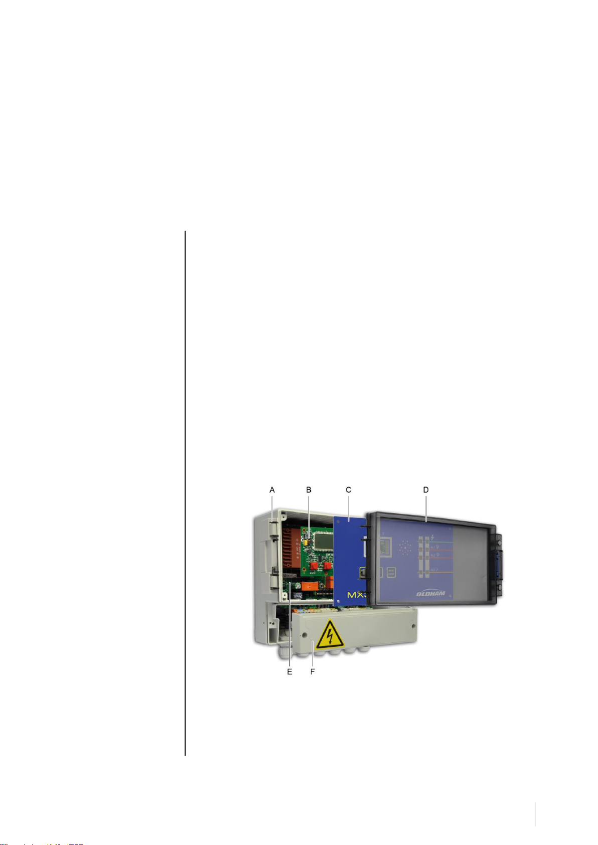
View: Front internal
The MX 32 controller is composed of the following components:
■ A wall-mounted enclosure (ref. A) equipped with a terminal cover (ref. F), a
faceplate (ref. C) and a transparent hinged cover (ref. D) ;
■ a power supply board (analog) (ref. E) ;
■ a display card (microprocessor) (ref. B).
Figure 1: Overall view of the MX 32 controller components.
Page 8
4
MX 32
Instruction Manual
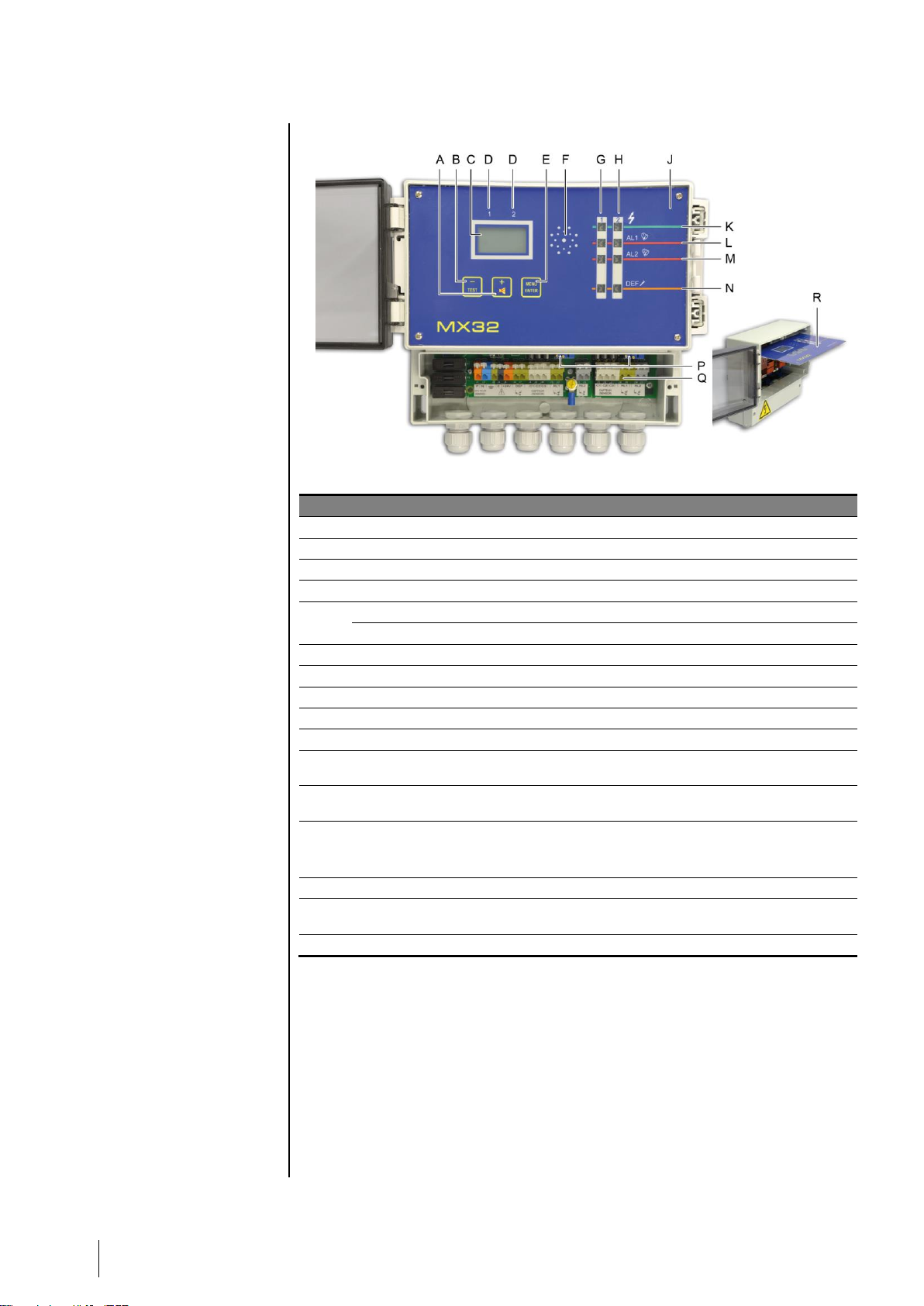
View: Front
Figure 2: Full view of the MX 32 controller.
Ref.
Function
A.
Button to increase the value displayed or flip to the next menu/option.
B.
Button to decrease the value displayed or flip to the previous menu/option.
C.
LCD screen displaying measurements, menus and options.
D.
Labels, for the LCD screen, indicating the display for Channel 1 or Channel 2.
E.
Menu access button. See page 16.
Button to confirm the value displayed.
F.
Buzzer activated in the case of fault or alarm if authorization is granted. See page 31.
G.
LEDs for Channel 1.
H.
LEDs for Channel 2.
J.
Removable faceplate; also see ref. R.
K.
LED lights up when the channel is active.
L.
Alarm threshold for level 1. LED lights up when the alarm threshold is exceeded or
when programming the alarm threshold for the channel.
M.
Alarm threshold for level 2. LED lights up when the alarm threshold is exceeded or
when programming the alarm threshold for the channel.
N.
Fault LED
■ Lights up when there is a fault in the channel.
■ Blinks during programming of the channel.
P.
Access to the zero and sensitivity settings (Figure 4, ref. O to R).
Q.
Connection terminals (sector, 24VDC, sensors, dry alarm contacts); front view with
protective cover removed.
R .
Removable faceplate in maintenance position.
Page 9
2 – General Introduction
5
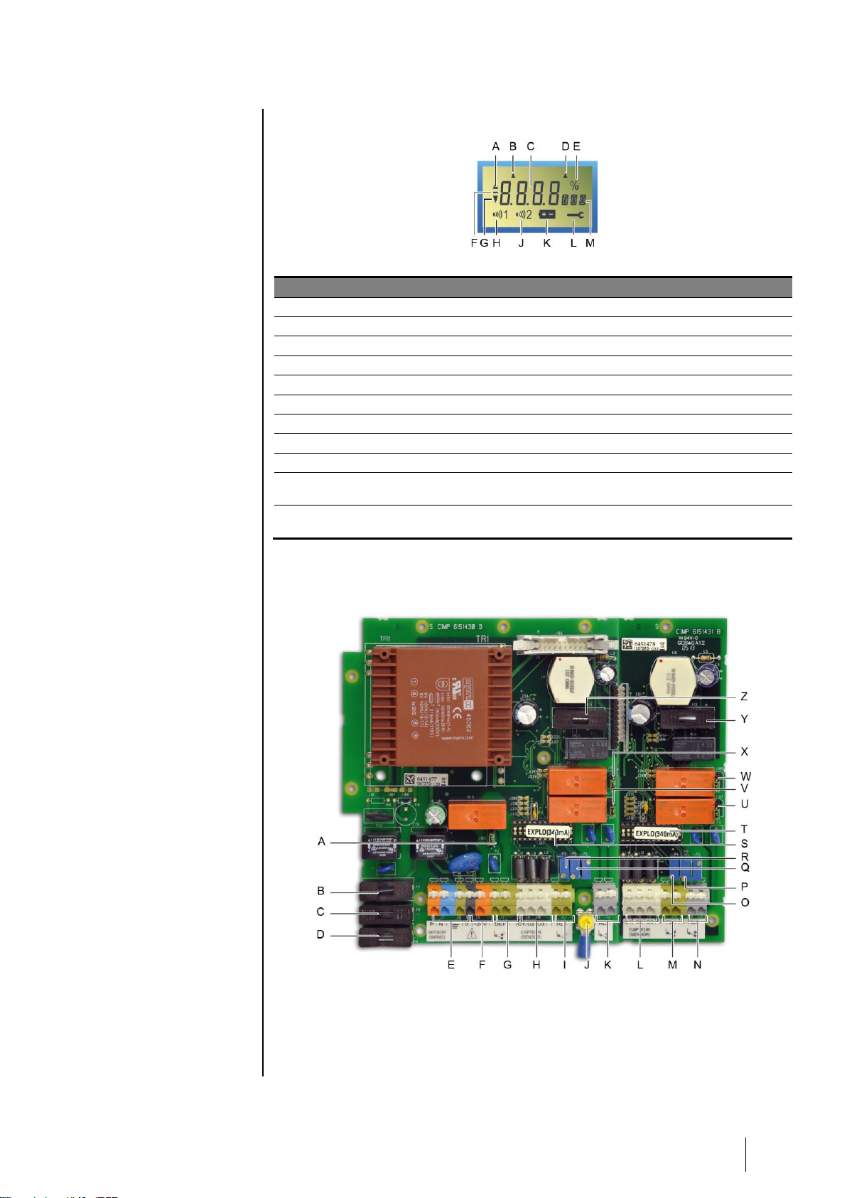
LCD Information
Figure 3: LCD Information.
Ref.
Function
See page
A.
Indicator for alarm threshold rising.
13
B.
Indicator that Channel 1 is selected. See Figure 2, ref. D.
14
C.
Digital indicator (measurement value, alarm threshold value, etc.)
13
D.
Indicator that Channel 2 is selected. See Figure 2, ref. D.
14
E.
Percent symbol.
18
F.
Negative sign.
G.
Indicator for alarm threshold falling.
18
H.
Symbol indicating level 1 alarm threshold (AL1) activated.
18
J
Symbol indicating level 2 alarm threshold (AL2) activated.
18
K.
Time delay after calibration (blocking the relays): the yellow LED blinks
and the icon is displayed.
18
L.
A Maintenance key icon is displayed while the programming and
calibration menu is being used.
18
View: Internal
Figure 4: Internal view.
Page 10

6
MX 32
Instruction Manual
Ref.
Function
See page
A.
Configuration jumper (J03) for Fault* relay settings.
■ Up position: Fault relay contact closed in alarm mode.
■ Down position: Fault relay contact open in alarm mode.
10
B.
F7 Fuse (5x20, 250 V AC - 2 A T) with 24V DC power supply.
8
C.
F9 Fuse:
■ 5x20, 250 V AC - 160 mA T with 230 VAC power supply.
■ 5x20, 250 V AC - 315 mA T with 115 VAC power supply.
8
D.
F8 Fuse:
■ 5x20, 250 V AC - 160 mA T with 230 VAC power supply.
■ 5x20, 250 V AC - 315 mA T with 115 VAC power supply.
8
E.
Sector power supply terminal (230 V AC or 110 V AC upon request) with
the following identifications: P (phase), N (neutral) and (ground).
8
F.
Power terminal block 24 V DC (0, + 24V).
8
G.
Fault relay terminal block. Contacts RCT, 250 V AC – 2 A. Contact
status not in alarm mode as defined by J03 (ref. A).
10
H.
Terminal block connection for channel #1 sensor.
9
I.
Relay terminal block RL 1 - Channel 1. Contacts RCT, 250 V AC – 2 A.
Contact status not in alarm mode as defined by J10 (ref. X).
10
J.
Secondary ground connection.
8
K.
Relay terminal block RL 2 - Channel 1. Contacts RCT, 250 V AC – 2 A.
Contact status not in alarm mode as defined by J05 (ref. V).
10
L.
Terminal block connection for channel #2 sensor.
9
M.
Relay terminal block RL 1 - Channel 2. Contacts RCT, 250 V AC – 2 A.
Contact status not in alarm mode as defined by J08 (ref. W).
10
N.
Relay terminal block RL 2 - Channel 2. Contacts RCT, 250 V AC – 2 A.
Contact status not in alarm mode as defined by J07 (ref. U).
10
O.
Zero settings (P4) for channel #2.
26
P.
Sensitivity settings (P6) for channel #2.
27
Q.
Sensitivity settings (P5) for channel #1.
26
R.
Zero settings (P3) for channel #1.
27
S.
Programming circuit (Explo 340 mA or 4-20 mA) for channel #1.
-
T.
Programming circuit (Explo 340 mA or 4-20 mA) for channel #2.
-
U.
Configuration jumper (J07) for Alarm 2*, channel #2 relay.
■ Up position: relay contact closed in alarm mode.
■ Down position: relay contact open in alarm mode.
-
V.
Configuration jumper (J05) for Alarm 2*, channel #1 relay.
■ Up position: relay contact closed in alarm mode.
■ Down position: relay contact open in alarm mode.
-
W.
Configuration jumper (J08) for Alarm 1*, channel #2 relay.
■ Up position: relay contact closed in alarm mode.
■ Down position: relay contact open in alarm mode.
-
X.
Configuration jumper (J10) for Alarm 1*, channel #1 relay.
■ Up position: relay contact closed in alarm mode.
■ Down position: relay contact open in alarm mode.
Y.
F13 Fuse (5x20, 250 V AC – 630 mA T).
-
Z.
F11 Fuse (5x20, 250 V AC – 630 mA T).
-
*alarm relays are configured as energized at the factory. This means that they are supplied with
power when not in alarm.
Page 11
3 – Installation and wiring
7
Chapter 3 │ Installation and wiring
Mounting the controller
The MX 32 controller can be installed in any location except for explosive
atmospheres. Ideally, the controller should be located in an area under
surveillance (security office, control room, equipment room, etc.).
The central controller cover opens at a 90° angle to the left. Make sure to
leave adequate space to completely open the cover once the central controller
is mounted.
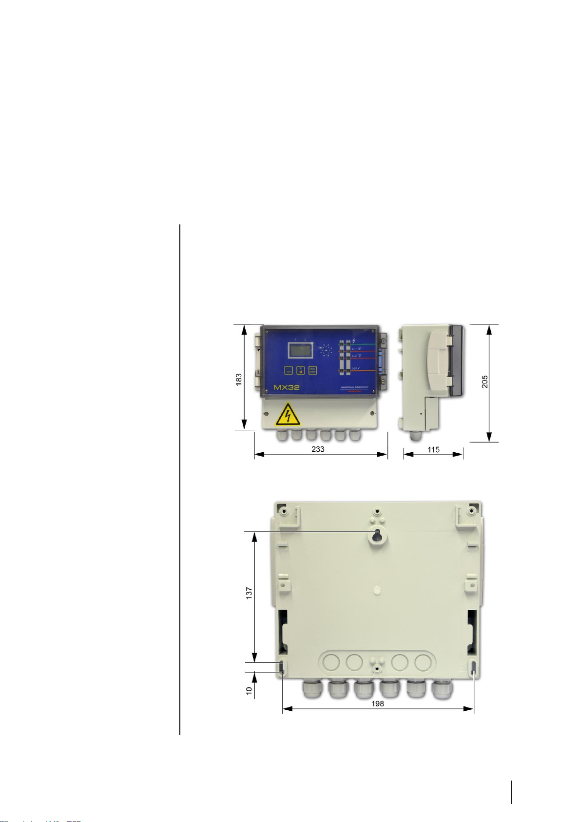
Figure 5: Dimensions of the controller
The dimensions for the wall-mounting of the enclosure are indicated on the back.
Figure 6: drilling dimensions for mounting the controller with three M4 screws.
Page 12
8
MX 32
Instruction Manual
Wiring
Before installing the controller, cut off the power supply.
Also refer to the Particular Specifications chapter on page 39.
The controller is intended for use in installation areas that meet Class II
overvoltage requirements and Degree 2 pollution requirements.
The electrical connection must be:
■ Performed by a specialist and conform to current regulations in force ;
■ Compliant with NF C 15-100.
Verify the current and the grid power supply (the grid power supply must
correspond to the supply indicated on the controller front plate). The operating
voltage is configured at the factory.
The MX 32 does not have an on/off switch.
Certain power supplies can cause serious or fatal injury. All
installation and wiring should be performed before turning on the
power supply.
Incorrect installation can lead to measurement errors or system
failure, all instructions in this manual must be followed carefully to
guarantee proper system operation.
Ground Connection Protection
The controller must be connected to a functional ground connection.
The ground terminal (yellow) (Figure 4, ref. J) is indicated with the following
symbol: .
The cable used must have a minimum diameter of 1.5 mm² and a maximum
diameter of 2.5 mm².
Refer to the wiring examples beginning on page 11.
Power
The MX 32 must be protected upstream by a differential bipolar circuit
breaker. The response curve must be type D.
Power supply
115 V AC
230 V AC
Differential bipolar circuit
breaker caliber
2 x 2 A
2 x 1 A
The cable used must have a minimum diameter of 1.5 mm² and a maximum
diameter of 2.5 mm².
There are two options for transformers suggested for use as a power supply
for the MX 32.
■ Bobbin transformer (standard default).
■ Toric Transformer (for connecting special sensors such as flame sensors,
etc.).
Page 13
3 – Installation and wiring
9
Power supply 230 V AC
The sector power supply must be wired to the two terminals marked P
(orange) and N (blue) (Figure 4, ref. E) on the 12 point terminal block for the
power supply card; also see the wiring example on page 11. Protection is
provided by fuses F8 and F9 (160 mA/250 VAC) (Figure 4, ref. C and ref. D).
Power supply 115 V AC
Protection is provided by fuses F9 and F8 (315mA/250 VAC) (Figure 4, ref. C
and ref. D).
Power supply 24 V DC
Must be connected to the terminals marked 0 (grey) and +24V (orange) on the
12 point terminal block for the power supply card (Figure 4, ref. F) as
indicated by the wiring example on page 11. Protection is provided by fuse F7
(2A/250 VAC) (Figure 4, ref. B).
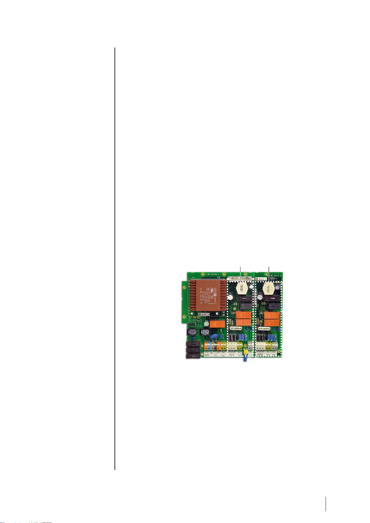
Measurement Channels
The MX 32 controller can be equipped with one or two adjustable and dual
measurement channels (see Figure 7). Three options are suggested at
purchase:
■ MX 32 with 2 measurement channels (dual);
■ MX 32 with 1 measurement channel (dual);
■ 1 extension card (to add on to a 1-channel controller).
The MX 32 controller will automatically recognize the number of measurement
channels installed (display).
Figure 7: the 2 measurement channels for the controller.
Sensors
The sensors must be connected to points C1, C2 and C3 on the 12 point
connector for each channel card, as indicated on the wiring example on page
10.
Wheatstone bridge 3 active wire explosive gas detectors
■ C1: mid-point (signal).
■ C2: detector filament.
■ C3: compensator filament.
Channel 1 Channel 2
Page 14

10
MX 32
Instruction Manual
4/20 mA 2 active wire sensors/transmitters
■ C1: signal (return to ground).
■ C2: not connected
■ C3: positive power supply (+24 Volts).
4/20 mA 3 active wire sensors/transmitters
■ C1: signal (return to ground).
■ C2: power supply (0 Volts).
■ C3: positive power supply +24 Volts.
Note
For each family of sensors, on the measurement channel circuits:
■ Programming will be carried out by Oldham (programming circuit pads).
■ A programming circuit (Explo 340 mA or 4-20 mA) will be inserted on the
mounting by the manufacturer (Figure 4, ref. S and T).
Alarm relays
The MX 32 controller uses two alarm relays per measurement channel which
correspond to two instant pre-programmed alarm thresholds 1 and 2.The
relays are energized (de-energized available on request) and voltage-free.
■ The relay corresponding to alarm 1 is connected to the RL1 (green)
terminals on the 12 point connector for each channel card.
■ The relay corresponding to alarm 2 is connected to the RL2 (grey)
terminals on the 12 point connector for each channel card.
The relay contacts can be used "normally open" (NO) or "normally closed"
(NC) by flipping the corresponding switch (Figure 4, ref. U or V for AL1 alarms
and references W and X for AL2 alarms).
Refer to the wiring examples beginning on page 11.
Relay fault
The MX 32 controller uses one "Fault" alarm per measurement channel (visual
and auditory) but a single shared "Fault" rela y for both c hannels . The fault
relay is energized and voltage-free. The shared fault relay can be connected
to the points marked DEF (fault) on the 12 point terminal block for the power
supply card.
The relay contact can be used "normally open" (NO) or "normally closed" (NC)
by flipping the corresponding switch (Figure 4, ref. L).
Refer to the wiring examples beginning on page 11.
Wiring examples
The following pages contain two examples of wiring.
Page 15
3 – Installation and wiring
11
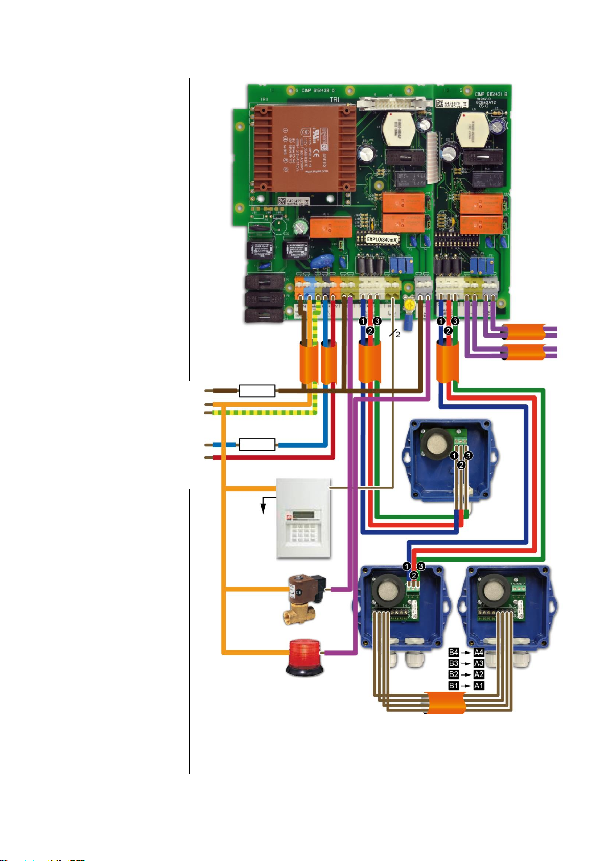
Figure 8: MX 32 controller with 1 explosive sensor on Channel 1 and dual explosive
sensors on Channel 2.
Grounding sector
0V DC
+24 V DC
Telephonic
transmitter
To the
telephone line
Gas valve, closed when
power is cut off*
Shared fault indicator
Fuse or
circuit breaker
Fuse
Contact alarm
Channel 2.
Contact alarm
Channel 1.
The AL1 and AL2 relays can be programmed as
energized or de-energized (factory settings).
The fault relays are energized.
The contact relays are available on the NO or
NC terminals according to the position of the
switch next to each relay.
*Capacity to cut the power to relays 120 VA-
30W resistive; use a relay with external power
source if necessary.
Page 16

12
MX 32
Instruction Manual
Figure 9: MX 32 controller with 1 explosive sensor on Channel 1 and 2 parking CO sensors
on Channel 2 (maximum of 5 loop-connected sensors).
Grounding sector
0V DC
+24 V DC
Telephonic
transmitter
To the
telephone line
Gas valve, closed
when power is cut off*
Shared fault indicator
Fuse or
circuit breaker
Fuse
Contact alarm
Channel 2.
Contact alarm
Channel 1.
The AL1 and AL2 relays can be programmed as
energized or de-energized (factory settings).
The fault relays are energized.
The contact relays are available on the NO or
NC terminals according to the position of the
switch next to each relay.
*Capacity to cut the power to relays 120 VA-
30W resistive; use a relay with external power
source if necessary.
Page 17

4 – Operating instructions
13
Chapter 4 │Operating instructions
Displays
Indications for start-up
Action or result
Illustration
■ Current version of the software and buzzer test.
■ Access code for menus currently programmed.
■ Display of current AL1 threshold for channel #1.
Simultaneously, the AL1 and Fault-channel 1
indicators light up.
■ Display of current AL2 threshold for channel #1.
Simultaneously, the AL2 and Fault-channel 1
indicators light up.
■ Display of current AL1 threshold for channel #2.
Simultaneously, the AL1 and Fault-channel 2
indicators light up.
■ Display of current AL2 threshold for channel #2.
Simultaneously, the AL2 and Fault-channel 2
indicators light up.
■ Time delay (in minutes) for (1) stabilization time
for the measurement channels.
During this time the two yellow DEF (fault)
indicators are lit up.
(1) Time is factory set.
Page 18

14
MX 32
Instruction Manual
■ Cyclic display of the measurement channels.
Note: The display alternates between the
measurements of each of the activated channels
(the unit and gas being detected is displayed).
Temporary display of a measurement channel
Action or result
Illustration
■ Select the channel to be displayed:
- Press (-) to display Channel 1.
- OR press (+) to display Channel 2.
■ Display of the measurement for the channel
selected.
... or.
■ One minute later, if the (-) or (+) buttons
are not pressed, the display will return to cyclic
display of the two measurement channels (if in
use).
Page 19

4 – Operating instructions
15
Cyclic display of the 2 measurement channels
Action or result
Illustration
■ Press (-) AND (+) together.
■ The alternating display (cyclic) of the 2
measurement channels is now activated.
No display of measurements after manual display
Action or result
Illustration
■ Display is presented as shown in the illustration
seen opposite (cyclic display).
■ Press (-) AND (+) together.
■ The measurements disappear and are replaced
by dashes. The MX 32 controller continues to
monitor the sensor(s) but the display is hidden.
No display of measurements after cyclic display
Action or result
Illustration
■ Alternate (cyclic) display of the 2 measurement
channels.
■ Press (-) AND (+) together.
Page 20

16
MX 32
Instruction Manual
■ The measurements disappear and are replaced
by dashes. The MX 32 controller continues to
monitor the sensor(s) but the display is hidden.
Navigating the menus
Reminder: for security reasons, only trained personnel (with access
codes) are authorized to use the menus listed below.
To quit a menu at any stage, press the (-) and (+) buttons
together.
Viewing the menus
Action or result
Illustration
■ Press the button (MENU/ENTER).
■ Request for access code.
Note: the first number is blinking.
If there is a response within one minute, the unit
will return to normal mode.
■ Enter the first digit of the code.
Press (-): to decrease the number.
Press (+): to increase the number.
Press (ENTER): to confirm the number.
■ Proceed to the next stage for each of the other 3
numbers in the code.
■ Final display of the access code.
■ Confirm the code by pressing (MENU/ENTER).
■ The menu flashing PRG (Programming) is
displayed.
See page 18 for instructions on using this menu.
■ Press (+) to display the CAL menu
(Calibration).
See page 23 for instructions on using this menu.
Page 21
4 – Operating instructions
17
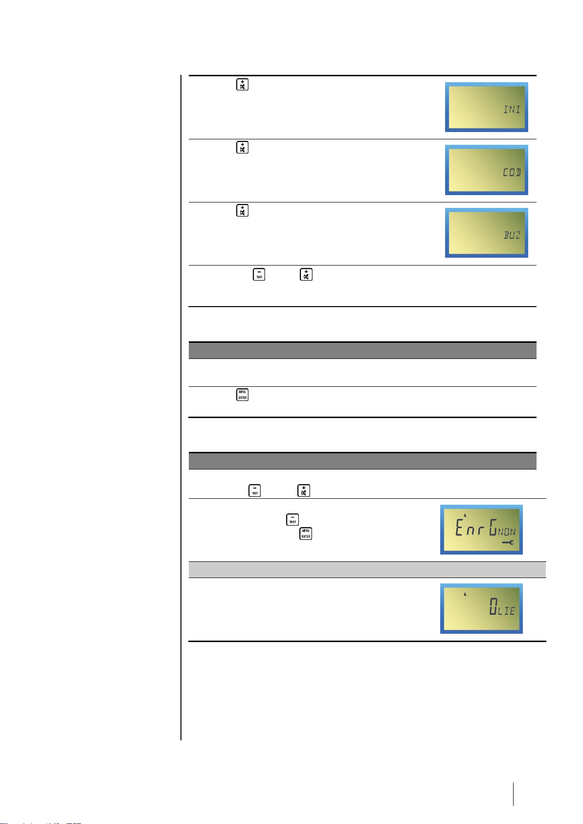
■ Press (+) to display the INI menu
(Initialization/Start-up).
See page 25 for instructions on using this menu.
■ Press (+) to display the COD menu (Access
Code).
See page 30 for instructions on using this menu.
■ Press (+) to display the BUZ menu (Buzzer).
See page 31 for instructions on using this menu.
■ Press the (-) and (+) buttons at the same
time to quit the list of menus without activating
them.
Menu Confirmation
Action or result
Illustration
■ Display the desired menu by following the
instructions described in the above paragraph.
■ Press (MENU/ENTER) to confirm the menu to be
used.
Exiting a menu (escape)
Action or result
Illustration
■ While using a menu it is possible to exit by
pressing (-) AND (+) together.
■ The screen will display Recording. If
necessary, press (-) to select No.
■ Confirm by pressing (MENU/ENTER).
Return to normal measurement display
■ The screen will display the current
measurement.
Page 22

18
MX 32
Instruction Manual
PRG Menu (Programming)
To quit a menu at any stage, press the (-) and (+) buttons
together.
This menu allows the user to program measurement channel configurations
such as:
Action or result
Illustration
■ The PRG indicator blinks.
Selecting the channel to be programmed
■ Confirm by pressing (MENU/ENTER).
The Channel 1 icon blinks indicating
Channel 1 has been selected.
■ To select Channel 2, press (+).
The Channel 2 icon blinks indicating
Channel 2 has been selected.
■ Confirm the channel to be programmed by
pressing (MENU/ENTER).
- ON blinks.
- The icon is displayed.
- The yellow fault indicator (Figure 2, ref.
N) for the corresponding channel blinks.
The alarm relays for the channel are
blocked.
Start-up or stopping the channel
■ Activating or deactivating the channel:
- (-) deactivates the channel (channel
stopped).
- (+) activates the channel (channel in
operation).
■ Confirm by pressing (MENU/ENTER).
Page 23

4 – Operating instructions
19
Selecting the gas to be detected
■ Press (-) to display a list of the gases
programmed. Then use to display the
other gases again.
■ Confirm by pressing (MENU/ENTER).
Selecting the unit of measurement
■ Press (-) or (+) to display a list of the
units programmed (%, LIE, PPM, PPB, UEG,
C, BAR, MG, ----).
■ Confirm by pressing (MENU/ENTER).
Selecting the measurement scale
■ The screen will display (for example):
■ Press (+) to modify the first digit of the
measurement scale.
■ Confirm by pressing (MENU/ENTER).
■ Use the same method for the other digits.
■ Confirm by pressing (MENU/ENTER).
Defining the AL1 alarm threshold
■ The alarm threshold indicator lights up
(Figure 2, ref. F) and the screen will display
(for example):
- : increasing alarm.
- : AL1 alarm.
- 40: current value for the alarm threshold.
- MAN: see next step.
■ Press (-) or (+) to define the first digit
of the AL1 alarm threshold. Confirm by
pressing (MENU/ENTER). Use the same
method for the rest of the digits for the
threshold.
Defining the direction (increasing/decreasing) for AL1 alarm
■ In this example, the display indicates
(increasing alarm).
- : increasing alarm (icon blinks).
- : AL1 alarm.
- 40: current value for the alarm threshold.
- MAN: see next step.
■ To proceed directly to the next step, press
(MENU/ENTER).
■ Press (-) or (+) to define the AL1
alarm direction.
Page 24

20
MX 32
Instruction Manual
- : increasing alarm.
- : decreasing alarm.
■ Confirm by pressing (MENU/ENTER).
Defining alarm acknowledgment (manual/automatic)
■ To proceed directly to the next step, press
(MENU/ENTER).
■ Press (-) or (+) to define the AL1
alarm acknowledgment.
- MAN : (-). Alarm clearing
(acknowledgment) by pressing the
(+) button once the measurement is
below the programmed alarm
threshold.
- AUT : (+). Automatic alarm clearing
(acknowledgment) once the
measurement is below the programmed
alarm threshold.
■ Confirm by pressing (MENU/ENTER).
Defining the time delay for triggering alarm relays
■ Press (-) or (+) to define the 4 digits
for the time delay (in minutes, seconds)
once the AL1 alarm relay is engaged.
Confirm the 4 digits by pressing
(MENU/ENTER)
Example: the value 10.20 indicates a delay
of 10 minutes and 20 seconds.
Defining the AL2 alarm threshold
■ Follow the same instructions for the AL2
alarm threshold. Comply with the above
paragraphs Defining the AL1 alarm
threshold to Defining the time delay for
triggering alarm relays.
Defining the time delay at start-up
■ Press (-) or (+) to define each of
the 4 digits for the time delay (in minutes,
seconds). Confirm the 4 digits by
pressing (MENU/ENTER)
Example: the value 10.20 indicates a time
delay at start-up of 10 minutes and 20
seconds.
Alarm threshold
exceeded
LED alarm
and buzzer
Delay
Alarm relay
switching
Page 25

4 – Operating instructions
21
Defining the type of sensor
■ To proceed directly to the next step,
press (MENU/ENTER).
■ Press (-) or (+) to define the type of
sensor connected.
- BRIDGE: sensor (Wheatstone bridge
output).
- EHP: explosive sensor 4-20 mA.
- FIRE: fire detector (ionic, optic, etc.).
- O2: oxygen detector 4-20 mA.
- OTH: another type of sensor (flame,
etc.).
- MAN: see next step.
■ Confirm by pressing (MENU/ENTER).
Defining the calibration mode for the
sensor
■ To proceed directly to the next step,
press (MENU/ENTER).
■ The MAN indicator blinks.
■ Press (-) or (+) to define the
operating mode for the yellow sensor LED:
- MAN: no visualization (blinking yellow
LED) by the MX 32 controller, of the
sensor being calibrated (sensor
maintenance mode).
- OTH: visualization (blinking yellow
LED) on the controller when the sensor
is being calibrated.
■ Confirm by pressing (MENU/ENTER).
Defining the time delay after calibration
mode
(displaying a time)
■ Press (-) or (+) to define the time
delay (in minutes). Confirm the 4 digits by
pressing (MENU/ENTER)
Saving programming
■ Press:
- (+) to select Yes. The programming
completed will be used.
- (-) to select No. The changes will be
abandoned and the old programm ing
will be saved.
■ Confirm by pressing (MENU/ENTER).
Page 26

22
MX 32
Instruction Manual
Return to measurement display
■ Indicating the current measurement.
If necessary, repeat the same procedure for the other channel.
Page 27

4 – Operating instructions
23
INI Menu (Initialization)
To quit a menu at any stage, press the (-) and (+) buttons
together.
This menu is used to automatically initialize the measurement curve managed
by the microprocessor with the sensor connected to the appropriate channel.
It is used in the following situations:
■ By Oldham when shipping new material.
■ At the initial installation.
■ When changing a sensor or a detector.
Action or result
Illustration
■ The INI indicator blinks.
Selecting the channel to initialize
■ Press (ENTER) to confirm.
The Channel 1 icon blinks indicating Channel 1
has been selected.
■ To select Channel 2, press (+).
The Channel 2 icon blinks indicating Channel 2
has been selected.
■ Confirm the channel to initialize by pressing
(ENTER).
- ON blinks.
- The icon is displayed.
- The yellow indicator of the corresponding
channel blinks (the channel relays are
blocked).
Confirming initialization
■ Press:
- (+) to select Yes. The initialization will
launch.
- (-) to select No. The initialization will be
abandoned.
■ Confirm by pressing (MENU/ENTER).
Page 28

24
MX 32
Instruction Manual
Return to normal measurement display
■ The screen will display the current
measurement.
Important: once the settings are
completed, perform a new
calibration for this measurement
channel; see the following
paragraph.
Page 29

4 – Operating instructions
25
Cal Menu (Calibration)
To quit a menu at any stage, press the (-) and (+) buttons
together.
Caution: the settings operations in this paragraph are reserved for
authorized, trained personnel because they may compromise
detection reliability.
The user must refer to the gas detector manual for calibration of
detectors.
The only way to verify the accuracy of the detection function of the sensor(s)
linked to the MX 32 controller is through calibration using a test gas.
Gas detectors are safety devices. Accordingly, Oldham recommends regular
testing of fixed gas detection installations. This type of test consists of
injecting a standard gas of sufficient concentration into the sensor to set off
the pre-adjusted alarms. This test does not, in any event, replace a full
calibration of the sensor.
Oldham also recommends completely calibrating detectors with a known and
certified concentration of gas every 3 or 4 months.
Frequency of gas testing depends on the industrial application in which the
sensors are used. Inspection should occur frequently during the months
following installation start up, later it may be spaced out if no significant
problem is observed. Time intervals between tests should not exceed 3
months.
If a detector does not react upon contact with gas, it must be calibrated.
Calibration frequency should be adapted based on test results. However, it
should not be greater than one year.
Oldham recommends using a test gas to calibrate detectors.
The site manager is responsible for implementing the safety procedures on
his site. Oldham is not responsible for implementing safety procedures.
Reminder: for security reasons, only trained personnel should be
authorized to use the following menus.
The Calibration menu will allow the user to perform zero control and settings
in a clean environment and the sensitivity of the test gas.
Calibration can be performed:
■ After initialization; see the following page.
■ For preventative maintenance (minimum and regular service); see
page 28.
Page 30

26
MX 32
Instruction Manual
After initialization
Action or result
Illustration
■ The CAL indicator blinks.
Selecting the channel to calibrate
■ Press (ENTER) to confirm.
The Channel 1 icon blinks indicating Channel 1
has been selected.
■ To select Channel 2, press (+).
The Channel 2 icon blinks indicating Channel 2
has been selected.
Zero settings
■ Confirm the channel to calibrate by pressing
(ENTER).
- Display of the current value.
X0 = zero settings.
- The icon is displayed.
- The yellow indicator of the corresponding
channel blinks (the channel relays are
blocked).
■ Make sure that the air is clean, if not, using a test
kit, inject air at the level of the detector at a flow
rate of 60 l/h, then wait for stabilization of the
signal.
If the display is not zero, adjust the zero
measurement by moving the zero potentiometer
corresponding to the appropriate channel (Figure
4, ref. R for Channel 1 or ref. O for Channel 2).
■ Confirm the zero by pressing (ENTER).
Page 31

4 – Operating instructions
27
Sensitivity settings
■ Inject the calibration gas (60 l/h) at sensor level
and wait for signal stabilization.
■ Confirm the entry in the sensitivity settings by
pressing (ENTER).
- Display of the current value.
XF = setting the.
- The icon is displayed.
- The yellow indicator of the corresponding
channel blinks (the channel relays are
blocked).
If necessary (display other than the value of the
calibration gas), adjust the sensitivity by moving
the sensitivity potentiometer corresponding to the
appropriate channel (Figure 4, ref. Q for Channel
1 or ref. P for Channel 2).
■ Confirm the sensitivity by pressing (ENTER).
Caution: never confirm without having injected
gas and completed the settings, at the risk of false
triggering.
Saving calibration
■ Press:
- (+) to select Yes. The completed
calibration will be saved.
- (-) to select No. The changes will be
abandoned and the old calibration will be
saved.
■ Confirm by pressing (MENU/ENTER).
Return to measurement display
■ The screen will display the current
measurement.
Page 32

28
MX 32
Instruction Manual
Preventative maintenance
Action or result
Illustration
■ The CAL indicator blinks.
Selecting the channel to calibrate
■ Press (ENTER) to confirm.
The Channel 1 icon blinks indicating Channel 1
has been selected.
■ To select Channel 2, press (+).
The Channel 2 icon blinks indicating Channel 2
has been selected.
Zero settings
■ Confirm the channel to calibrate by pressing
(ENTER).
- Display of the current value (±0).
X0 = zero settings.
- The icon is displayed.
- The yellow indicator of the corresponding
channel blinks (the channel relays are
blocked).
■ Make sure that the air is clean, if not, using a test
kit, inject air at the level of the detector at a flow
rate of 60 l/h, then wait for stabilization of the
signal.
If the display is a value other than zero, adjust the
zero measurement using the (+) or (-)
buttons.
Sensitivity settings
■ Inject the calibration gas (60 l/h) at sensor level
and wait for signal stabilization.
■ Confirm the entry in the sensitivity settings by
pressing (ENTER).
- Display of the current value (±0).
XF = sensitivity settings (blinking icon).
- The icon is displayed.
- The yellow indicator of the corresponding
channel blinks (the channel relays are
blocked).
If necessary (displayed value other than the value
of the calibration gas), adjust the sensitivity by
using the (+) or (-) buttons.
Page 33

4 – Operating instructions
29
■ Confirm the sensitivity by pressing (ENTER).
Caution: never confirm without having injected
gas and completed the settings, at the risk of false
triggering.
Saving calibration
■ Press:
- (+) to select Yes. The completed
calibration will be saved.
- (-) to select No. The changes will be
abandoned and the old calibration will be
saved.
■ Confirm by pressing (MENU/ENTER).
Return to measurement display
■ The screen will display the current
measurement.
Page 34

30
MX 32
Instruction Manual
Cod Menu (Access code)
To quit a menu at any stage, press the (-) and (+) buttons
together.
Action or result
Illustration
■ The COD indicator blinks.
■ Press (ENTER) to confirm.
Defining the code
■ The current code is displayed.
■ The first digit blinks. Enter the first digit of the new
code using the (+) or (-) buttons.
■ Confirm the first digit by pressing (ENTER).
■ Proceed to the next stage for each of the other 3
digits in the code.
Saving the new code
■ Press:
- (+) to select Yes. The new code will be
saved.
- (-) to select No. The changes will be
abandoned and the old code will be saved.
■ Confirm by pressing (MENU/ENTER).
Return to measurement display
■ The screen will display the current
measurement.
Page 35

4 – Operating instructions
31
Buz Menu (Buzzer)
Action or result
Illustration
■ The BUZ indicator blinks.
■ Press (ENTER) to confirm.
Defining the buzzer action
■ The ON or OFF icon blinks, depending on the
current buzzer configuration.
■ Select On or Off:
- On: the buzzer will be activated in the case of
alarm or a fault. Press (+).
OFF: the buzzer will not be activated in the
case of alarm or a fault. Press (-).
■ Press (ENTER) to confirm.
Saving the new buzzer settings
■ Press:
- (+) to select Yes. The new buzzer
settings will be saved.
- (-) to select No. The old buzzer settings
will be saved.
■ Confirm by pressing (MENU/ENTER).
Return to measurement display
■ The screen will display the current
measurement.
Page 36

32
MX 32
Instruction Manual
Page 37

5 – Cleaning, servicing and maintenance
33
Chapter 5 │Cleaning, servicing and
maintenance
Cleaning
Do not use alcohol- or ammonia-based liquids to clean the central controller. If
necessary, clean the exterior of the enclosure with a damp cloth.
Maintenance and servicing
The controller does not require special servicing.
Adjustments
Caution: the settings operations in this paragraph are reserved for
authorized, trained personnel because they may compromise
detection reliability.
If it is necessary to re-adjust the sensors, this operation must only be
completed by a qualified personnel. First, the front cover must be opened
(Figure 2, ref. P) on the controller. Refer to the Viewing the menus paragraph
on page 16.
Zero adjustment
Use the following settings:
■ Channel 1: P3 (Figure 4, ref. R).
■ Channel 2: P4 (Figure 4, ref. O).
Sensitivity adjustments
Use the following settings:
■ Channel 1: P5 (Figure 4, ref. Q).
■ Channel 2: P6 (Figure 4, ref. R).
Page 38

34
MX 32
Instruction Manual
Calibration
Gas detectors are safety devices. Accordingly, OLDHAM recommends regular
testing of fixed gas detection installations. This type of test consists of
injecting a standard gas of sufficient concentration into the sensor to set off
the pre-adjusted alarms. This test does not, in any event, replace a full
calibration of the sensor.
Frequency of gas testing depends on the industrial application in which the
sensors are used. Inspection should occur frequently during the months
following installation start up, later it may be spaced out if no significant
problem is observed.
If a detector does not react upon contact with gas, it must be
calibrated. Calibration frequency should be adapted based
on test results. However, it should not be greater than one
year.
Safety Procedures
The site manager is responsible for implementing the safety procedures on
his site. Oldham is not responsible for implementing safety procedures.
■ Refer to the Menu Initialization paragraphs (page 23).
■ Do not forget to complete a system start-up after changing the sensor by
using the "INI" menu (Menu Initialization (INI) paragraph, on page 23).
Fuse replacement
Replacement of the fuses should only be performed by a qualified
professional. The fuses in use must conform to CEI 127 regulations (timedelayed, low breaking capacity, 250 V AC power source). Please see the
following paragraph.
Parts
Description
Reference
Fuse F7 (2 A T, 250 V AC) – Versions 115 or 230 V AC.
6 154 624
Fuse F8 (315 mA T, 250 V AC) – Version 115 V AC.
6 154 722
Fuse F8 (160 mA T, 250 V AC) – Version 230 V AC.
6 154 723
Fuse F9 (315 mA T, 250 V AC) – Version 115 V AC.
6 154 722
Fuse F9 (160 mA T, 250 V AC) – Version 230 V AC.
6 154 723
Fuse F11 (630 mA T, 250 V AC).
6 154 627
Fuse F13 (630 mA T, 250 V AC).
6 154 627
Programming strip 340 mA
6 353 442
Programming strip 4-20 mA
6 353 443
Dual channel analog card
6 451 476
Single channel analog card
6 451 477
Channel extension card
6 451 478
Micro card (display)
6 451 475
Page 39

6 – Declaration of Conformity
35
Chapter 6 │Technical specifications
Page 40

36
MX 32
Instruction Manual
Page 41

7 - Technical specifications
37
Chapter 7 │Technical specifications
Case
Enclosure:
wall-mount.
Dimensions:
240 x 205 x 120 mm.
Material:
ABS plastic
Cable input/outputs:
6 x PG9 type cable glands.
Protection:
IP65.
Power supply
Power supply:
■ 115 or 230 VAC.
■ 21 V to 30 V DC.
Power consumption:
30 VA.
Connections
Type:
spring terminal.
Cable diameter:
2.5 mm² maximum.
Measurement Channels
Number:
1 or 2.
Type:
■ Wheatstone bridge type explosive sensor.
■ 4/20 mA to 2 or 3 fils.
Measurement:
simultaneous channel measurement.
Measurement Ranges
Type :
programmable independently for each channel.
Number of measurement
points:
continuous programming from 0 to 9999.
Display
Position:
on the front.
Type:
■ liquid-crystal display (LCD).
■ 4 digits of 7 segments each, 3 characters of 14
segments each, fixed or drop-down icons for
each channel.
■ 4 light-emitting diodes (LEDs) per channel (on,
AL1, AL2, fault).
Unit description:
definable for each channel.
Gas description:
definable for each channel.
Keypad:
buttons for menu access, indicators and acknowledgment.
Page 42

38
MX 32
Instruction Manual
Alarms
Type:
■ 2 independent thresholds per channel defined
by the user.
■ manual or automatic clearing for increasing or
decreasing values as programmed.
■ visualization with red indicator.
■ output relays (alarms 1 and 2).
Relay:
■ 2 independent alarm relays per channel
energized or de-energized, programmable by
the manufacturer.
■ 1 relay with energized disturbance.
■ open or closed contact configurable for all the
relays using a switch.
Breaking capacity:
2A - 250 VAC, 2A - 30 VDC.
LED:
4 electroluminescent diodes.
Integrated audible alarm:
■ buzzer.
■ alarm sound level:
- to 50 cm: 72 to 74 dB.
- to 100 cm: 66 to 68 dB.
Sensors
■ 1 OLC 10 combustible gas detector or 2 OLC
10 TWIN detectors for the detection of
methane, butane, propane in boiler rooms and
LPG, CNG or H2 in parking lots.
■ 1 OLCT 10 combustible gas detector for the
detection of methane, butane, propane in boiler
rooms and LPG, CNG or H2 in parking lots.
■ 1 to 5 detectors, also OLCT 10 for the detection
of CO, NO and NO2.
Cable length (1.5 mm² diameter).
■ Wheatstone bridge: 300 m max. per channel
■ 4 / 20 m A: 2000 m m ax. per channel.
Operating conditions
Ambient temperature:
-10 to +55°C
Storage temperature:
-10 to +45°C
Humidity:
5 to 95 % non condensing
Certifications
ATEX Directive 94/9/EC:
category (3) G for metrology in the detection of
explosive gases EN 61779-1 and 4 in Zone 2.
Low Voltage Directive:
in compliance with EN 61010-1:10.
Electromagnetic
Compatibility (EMC)
Directive:
in compliance with EN 50270:06.
Page 43

8 – Particular specifications
39
Chapter 8 │ Particular Specifications
Particular Specifications for use in Explosive Atmospheres in Accordance with
the European ATEX 94/9/CE Directive.
The MX 32 detection controller intended for the measurement of explosive
gases, conforms to European ATEX Directive 94/9/CE pertaining to explosive
atmospheres.
Due to their metrological performances as tested by INERIS (French National
Institute for Industrial Environment and Risks), the MX 32 paired with Oldham
CEX 300 and TBGW-EX detectors as well as those in the OLC/OLCT series:
20, 40, 50, 60, 100 and OLCT IR is c lassified as a safety device. The
controller can also reduce the risk of explosion by sending data to outside
units.
Information in following paragraphs must be taken into account and followed
by the person responsible for the equipment installation site. Refer to the
provisions of European ATEX Directive 1999/92/EC, concerning the
improvement of safety protection and the health of workers exposed to the
risks of explosive atmospheres.
Specifications for mechanical and electrical
installations in Explosive Zones.
All installations must be in compliance with currently enforced standards,
notably standards EN 60079-14, EN 60079-17, and EN 50281-1-2.
The MX 32 controller must not be subject to intense mechanical vibration and
must be installed in a safe area away from explosive atmospheres.
It is very important to refer to the user and start-up manuals for the gas
detectors being used.
For intrinsically safe installations, the person responsible for the IS
installation, called “the system designer,” must establish a system document
demonstrating that the entire Sensor/Cable/Power Supply system is
Intrinsically Safe. See the EN 50039 standard for group II and the EN 50394-1
standard for group I to prepare this document.
Metrological specifications
The controller conforms with the following European standards.
With Explosive Gas Detectors
■ European standards EN 50054 and EN 50057 for methane (calibration
gas), propane and hydrogen gases (gas following response curves), when
Page 44

40
MX 32
Instruction Manual
the controller is used with CEX 300 gas detectors and those in the
OLC/OLCT series including 20, 40, 50, 60, 100 and OLCT IR. Where the
controller is used with other types of detectors delivering a current of 4/20
mA, they must conform to ATEX Directive 94/9/EC, Annex II, paragraph
1.5 and be compatible with the characteris tics des cribed therein (r ef er to
the controller transfer curve in Figure 10).
■ European standard EN 50271.
Oxygen gas detectors
■ European standard EN 50104 when the controller is used with OLCT 20,
40, 50, 60 and TBGW-EX gas detectors. Where the controller is used with
other types of detectors delivering a current of 4/20 mA, they must conform
to ATEX Directive 94/9/EC, Annex II, paragraph 1.5 and be compatible
with the characteristics described therein (refer to the controller transfer
curve in Figure 11).
■ European standard EN 50271.
Connecting detectors other than Oldham
detectors to the MX 32 controller
Any user wishing to use detectors other than Oldham detectors must ensure
that they are compatible with the controller, in order for the unit to be
considered a safety device.
Configuration transfer curve 0 to 100 % LEL
The following curve demonstrates the controller response in terms of values
measured and treatment of faults, as a function of the value of the input
current delivered by the detector. In the case that the user connects a nonOldham brand detector to the MX 32 controller, the user must ensure that the
transfer curve is compatible with the input characteristics for the controller, so
that the information delivered by the detector will be properly interpreted. In
addition, the controller must provide sufficient supply voltage, taking into
account voltage drops in the cables.
Figure 10: Configuration transfer curve 0 to 100 % LEL
LEL Display in %
ABOVE
100% LEL
0% LEL
-15% LEL
Fault
Fault
Signal delivered by
the detector in mA
Page 45

8 – Particular specifications
41
Caution: when the measurement is above or equal to 100 % LEL,
the measurement controller records that the scale has been
exceeded; the channel switches to alarm and fault mode. The user is
responsible for manually rearming these settings, following the
safety regulations applicable at their site. Rearming can be
accomplished by restarting the controller or through a maintenance
operation.
Configuration transfer curve 0 to 30.0 % oxygen
The following curve demonstrates the controller response in terms of values
measured and treatment of faults, as a function of the value of the input
current delivered by the detector. In the case that the user connects a nonOldham brand detector to the MX 32 controller, the user must ensure that the
transfer curve is compatible with the input characteristics for the controller, so
that the information delivered by the detector will be properly interpreted. In
addition, the controller must provide sufficient supply voltage, taking into
account voltage drops in the cables.
Figure 11: Configuration transfer curve 0 to 30 % oxygen
Power supply and resistance characteristics
■ Maximum current available between terminals 2 and 3: 250 mA
under 19 V.
■ Maximum voltage without load between terminals 2 and 3: 30 V.
■ Resistance (outside of the intrinsic safety barrier) between terminals
1 and 2: 47 ohm.
Markings:
OLDHAM Arras
0080
II (1) (2) G
INERIS 04ATEX0064
Display in %
oxygen volume
Fault
Fault
Signal delivered by
the detector
Page 46

42
MX 32
Instruction Manual
Page 47

Page 48

44
The Fixed Gas Detection Experts
EUROPEAN PLANT AND OFFICES
Z.I. Est – rue Orfila CS 20417 – 62027 ARRAS Cedex FRANCE
Phone: +33 (0)3 21 60 80 80 – Fax: +33 (0)3 21 60 80 00
Web site: http://www.oldhamgas.com
AMERICAS
Phone: +1-713-559-9280
Fax: +1-281-292-2860
americas@oldhamgas.com
ASIA PACIFIC
Phone: +86-21-3127-6373
Fax: +86-21-3127-6365
sales@oldhamgas.com
EUROPE
Phone: +33-321-608-080
Fax: +33-321-608-000
info@oldhamgas.com
 Loading...