

Page 1

OOPPEERRAATTIINNGG AANNDD
M
MAAIINNTTEENNAANNCCEE
M
MAANNUUAALL
Réf.:
CD00002
Code: 06 MT MX2100 GB02
Page 2

3
OOLLDDHHAAMM SS..AA..
GAS DETECTION AND DUST ANALYSIS
We are delighted that you have chosen an OLDHAM S.A. instrument and would like to thank you for your
choice.
We have taken all the necessary measures to ensure that your instrument provides total satisfaction.
Now it is important to read this document carefully.
EEXXTTEENNTT OOFF RREESSPPOONNSSIIBBIILLIITTYY
* OLDHAM S.A. declines its responsibility towards any person for material damage, physical injury or death
resulting wholly or partly from inappropriate use, installation or storage of its equipment resulting from failure to
observe instructions and warnings and/or standards and regulations in force.
* OLDHAM S.A. neither supports nor authorises any company, physical or moral person to assume responsibility on
behalf of OLDHAM S.A., even if it is involved in the sale of OLDHAM S.A. products.
* OLDHAM S.A. cannot be held responsible for direct or indirect damage or be required to pay direct or indirect
compensation resulting from the sale or use of any of its products IF THESE PRODUCTS HAVE NOT BEEN
DEFINED AND CHOSEN BY OLDHAM S.A. FOR THEIR SPECIFIC USE.
CCLLAAUUSSEESS CCOONNCCEERRNNIINNGG PPRROOPPEERRTTYY
* Drawings, plans, specifications and information included in this document contain confidential information that is
the property of OLDHAM S.A.
* None of this information may be reproduced, copied, divulged or translated, by physical, electronic or any other
means, nor used as the basis for the manufacture or sale of OLDHAM S.A. equipment or for any other reasons
without prior consent from OLDHAM S.A.
WWAARRNNIINNGGSS
* This document is not contractually binding. In the interests of its customers, OLDHAM S.A. reserves to modify the
technical specifications of its equipment without notice, in order to improve its performance.
* READ THIS MANUAL CAREFULLY BEFORE FIRST USE OF THE EQUIPMENT: this manual must be
read by any person who is or will be responsible for using, maintaining or repairing this equipment.
* This equipment will only provide the announced performance levels if it is used, maintained and repaired
according to OLDHAM S.A. directives, by OLDHAM personnel or by personnel approved by OLDHAM
S.A.
GGUUAARRAANNTTEEEE
2 years guarantee in normal conditions of use on parts and technical labour, return in our workshops, excluding
consumables (sensors, filters, etc.)
Page 3

4
CONTENTS
I. INTRODUCTION ...................................................................................................................6
1. POWER SUPPLIES .................................................................................................................. 6
1.1. General power supply....................................................................................................... 6
1.1.1. Recharging of the battery pack......................................................................................... 6
1.2. Memory saving.................................................................................................................. 6
2. MEASURING CELLS .............................................................................................................. 6
2.1. Layout of cells on top of appliance: examples of configuration....................................... 7
2.2. Explosimetric cell ............................................................................................................. 7
2.3. Toxic gas and oxygen metering cells ................................................................................ 7
2.4. DETECTION OF “VERY HEAVY” EXPLOSIVE GAS.................................................... 7
3. DISPLAY UNIT........................................................................................................................ 7
4. VISUAL INDICATIONS.......................................................................................................... 8
5. AUDIO ALARMS..................................................................................................................... 8
6. REMOTE SAMPLING ............................................................................................................. 8
6.1. Electric pumping system BP2100 ..................................................................................... 8
6.2. Manual pumping system ................................................................................................... 8
6.3. The various probes ........................................................................................................... 8
7. CARRYING THE MX 2100: OPTIONS.................................................................................. 9
7.1 Positioning the appliance................................................................................................. 9
7.2 MX 2100 as beacon .......................................................................................................... 9
7.3 MX 2100 on shoulder strap .............................................................................................. 9
8. COMMUNICATION SOFTWARE COM 2100....................................................................... 9
9. "TWINCALL" CALIBRATION STATION........................................................................... 10
10. "TWINCALL" TESTBENCH................................................................................................. 10
II. UTILIZATION ......................................................................................................................10
1. FUNCTIONS OF KEYS: ACCESSIBLE BELOW THE DISPLAY UNIT ON THE
APPLIANCE'S FRONT PANEL................................................................................................... 10
2. READING MEASUREMENTS.............................................................................................. 11
3. SWITCHING ON.................................................................................................................... 11
3.1. Switching on in standard mode....................................................................................... 11
3.2. Switching on with choice of reference explosive gas...................................................... 12
4. SWITCHING OFF................................................................................................................... 12
5. DISPLAY UNIT LIGHTIN G.................................................................................................. 13
6. SCROLLING THROUGH MEMORIZED PARAMETERS.................................................. 13
6.1. "Roundsman" function.................................................................................................... 14
7. ALARMS................................................................................................................................. 14
7.1 "Gas" alarms.................................................................................................................. 14
7.2 Fault alarms.................................................................................................................... 15
Page 4

5
7.3 Acknowledging alarms.................................................................................................... 15
7.3.1. Acknowledging gas alarms............................................................................................. 15
7.3.2. Acknowledging fault alarms........................................................................................... 16
8. MEASUREMENTS................................................................................................................. 16
8.1. Display of instantaneous measurements......................................................................... 16
8.1.1. In "natural diffusion" mode............................................................................................ 16
8.1.2. With electric pumping systems........................................................................................ 16
8.1.3. With manual pumping systems........................................................................................ 16
8.2. Automatic switching to "0 -100% GAS" range................................................................16
8.3. Memorizing histogram measurements............................................................................ 16
8.3.1. Operating principle ........................................................................................................ 17
9. PRINTING DATA (VIA COM 2100)..................................................................................... 17
III. SPECIAL INSTRUCTIONS FOR USE IN ATEX EXP LOSIVE ATMOSPHERES ..... 18
IV. MAINTENANCE...................................................................................................................18
1. ACCESS TO MAINTENANCE MENUS ON MX 2100 ....................................................... 19
1.1 Channel programming menu.......................................................................................... 19
1.2. Cell calibration menu........................................................................................................ 21
1.3. Auto-zero menu ................................................................................................................. 21
1.4. Date and time management menu..................................................................................... 21
1.5. Exit menu........................................................................................................................... 22
2. ALARM TEST WITH TESTBENCH..................................................................................... 22
3. CALIBRATING CELLS WITH CALIBRATING STATION ............................................... 22
V. COM 2100 SOFTWARE.......................................................................................................22
VI. CHARGER MODULE..........................................................................................................26
VII. ACCESSORIES .....................................................................................................................26
VIII. SPARE PARTS ......................................................................................................................26
IX. TECHNICAL CHARACTERISTICS .................................................................................27
1. MX 2100 APPLIANCE........................................................................................................... 27
2. MEASURING CELLS (NON-EXHAUSTIVE LIST)............................................................ 30
Page 5
6
II..
IINNTTRROODDUUCCTTIIOONN
• The MX 2100 is a portable gas detector that can be used in explosive atmospheres in surface industries (Group
II) and in mines containing firedamp (Group I).
• Its basic function is the simultaneous detection of four gases present in the air and this can be extended to six
gases .
• These gases can be explosive, toxic or oxygen.
11..
PPOOWWEERR SSUUPPPPLLIIEESS
1.1. General power supply
The MX 2100 is power-supplied by a rechargeable battery pack (NiMH) or non-rechargeable AAA alkaline batteries.
In normal service conditions, operating autonomy varies according to the configuration (cells) and the power supply
(rechargeable or non-rechargeable batteries) with a standard autonomy of 14 hours.
1.1.1. Recharging of the battery pack
With an intelligent battery charger integrated in the appliance (see the section on CHARGERS).
Average charging time: 2 hours 30 minutes
1.2. Memory saving
A second lithium battery ensures the storage of the MX 2100's specific data, such as when the main battery set is
completely discharged. This lithium battery has an average service life of five years.
IMPORTANT: The appliance is certified for utilization in explosive atmospheres in Groups I and II, and only
when it is equipped with non-rechargeable or rechargeable batteries of a type recommended by the
manufacturer.
22..
MMEEAASSUURRIINNGG CCEELLLLSS
IMPORTANT: The intelligent cell units shall be:
- connected before switching on the MX 2100
- interchangeable outside area.
Non-rechargeable or
rechargeable batteries
Page 6
7
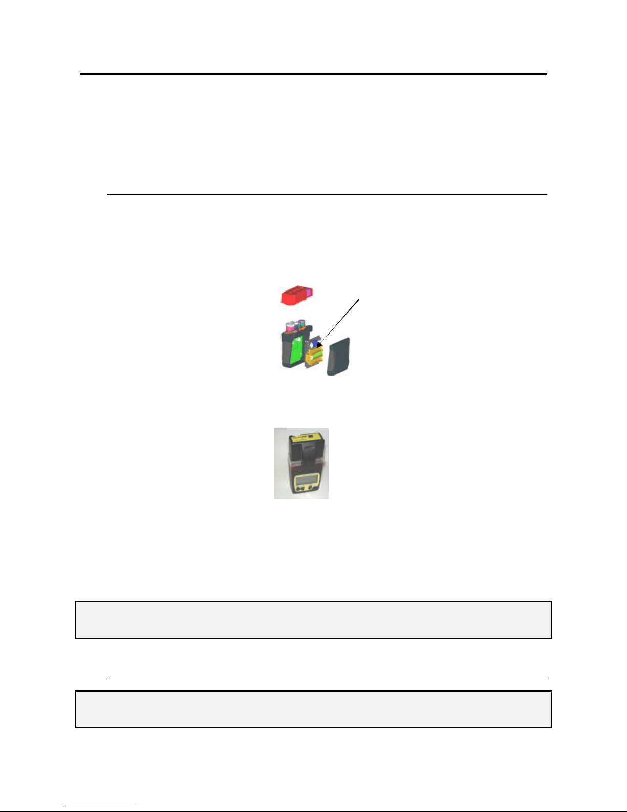
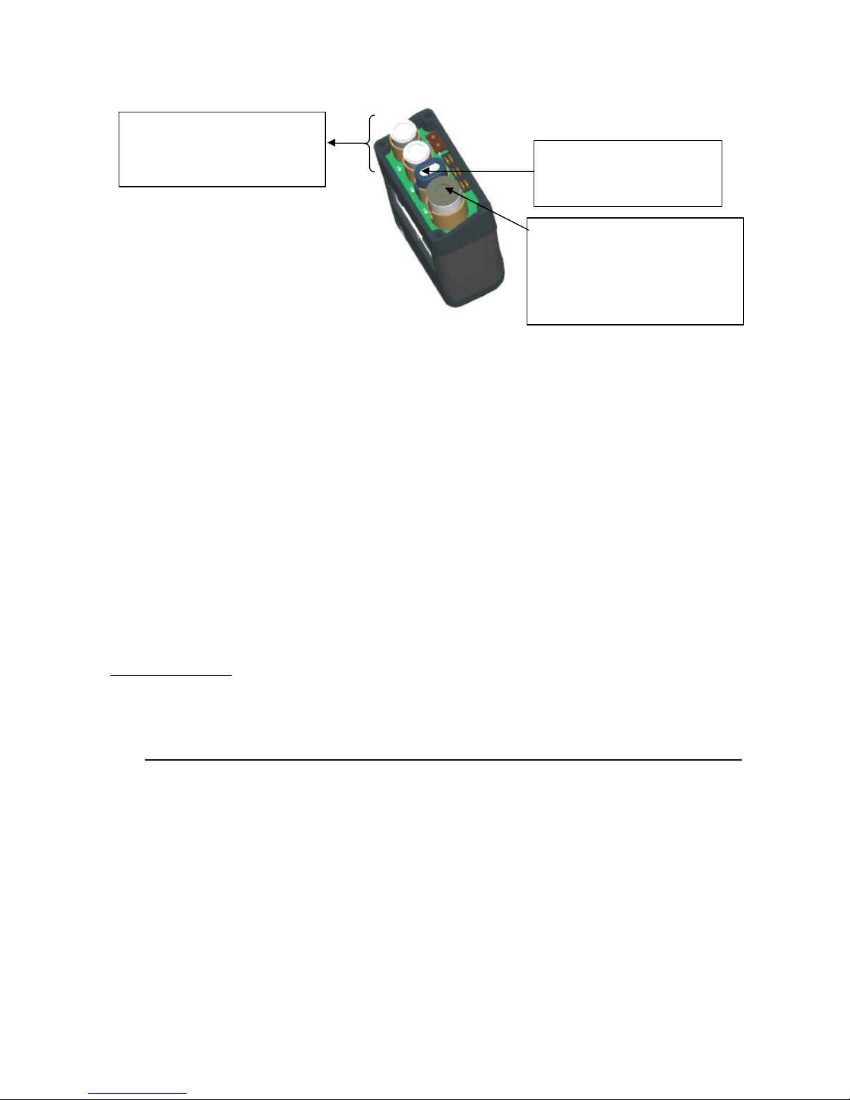
2.1. Layout of cells on top of appliance: examples of configuration
-
2.2. Explosimetric cell
This removable, interchangeable and intelligent cell unit can detect explosive gases in the range 0 to 100% LEL and/or
0 to 100% by volume, as applicable.
It is equipped with a cell body and filaments, and must be positioned in the MX 2100 as indicated above.
2.3. Toxic gas and oxygen metering cells
These removable, interchangeable and intelligent cell units are fitted with an electrochemical cell and electronic
components, including an EEPROM memory in which OLDHAM has stored the cell's specific characteristics
(measuring range, various correction coefficients, STEL and TWA alarms, date of manufacture, serial number, etc.).
Another item of data called the "wear rate" is used by the MX 2100 to automatically determine the optimal time to
replace the cell.
These types of cell unit are therefore also referred to as "intelligent units". They are po sitioned as indicated above (see
section 2.1).
2.4. DETECTION OF “VERY HEAVY” EXPLOSIVE GAS
The explosimetric cells of the Oldham portable detectors detect most explosive gases. However, for “heavy” gas and
vapours (with vapour density over three), it is ma ndatory to use a pump (manual or automatic) and/or to remove the
protective filter located on the explosimetric cells, in order to improve the detection speed.
"ALL GAS" RANGE
This function is particularly adapted to explosive gases with a density lower than three. For heavier gases or vapours, it
is mandatory to choose a specific range and use a pump (manual or automatic) and/or to remove the protective filter
located on the explosimetric cells, in order to improve the detection speed.
33..
DDIISSPPLLAAYY UUNNIITT
This is an LCD type display unit which lights up automatically in backlit mode in case of alarm or fault.
It is also a graphic display unit so as to optimize the readability of measurements.
Its displays measurements:
- 5 measurements with units and types of gas,
- indication of the channel to be calibrated, where applicable.
It also displays parameters:
- date and time,
- minimum – maximum,
- mean STEL and TWA values,
- remaining autonomy (by bar graph),
- roundsman (name).
Explo cell. 0 to 100% LEL
or Explo/Katharo 0 to 100%
LEL /0 to 100% GAS
TOX cells (small models) or
oxygen cell with service life of
1 year (small model).
Oxygen cell with service life of
2 years (large model) or
- CO/H2S
- Semiconductor
- SO2, ETO, etc.
- CO2 IR
Page 7
8
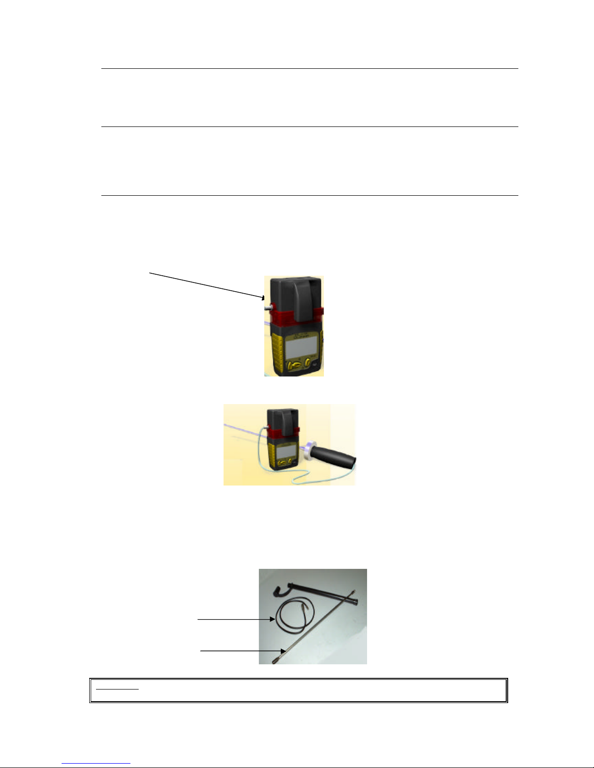
Semi-rigid probe
44..
VVIISSUUAALL IINNDDIICCAATTIIOONNSS
A set of indicator lights installed on the top of the appliance indicates alarms which can be seen from every direction,
whatever the working environment.
55..
AAUUDDIIOO AALLAARRMMSS
The user is also warned by a built-in buzzer when an alarm is triggered.
N.B. On option, the MX 2100 can be equipped with a vibrator.
66..
RREEMMOOTTEE SSAAMMPPLLIINNGG
The MX 2100 can be equipped with a sampling system to measure gas concentrations either in normally inaccessible
locations or before entering places which may be contaminated by gas (such as tanks, sewers or tunnels).
6.1. Electric pumping system BP2100
The snap-in pump unit is fitted to the top of the appliance, like the charger unit.
6.2. Manual pumping system
By using the charge unit equipped with an air inlet (olive), it is also possible to connect up a manual pumping system
(tube/bulb/probe).
6.3. The various probes
The "manual" or "electric" sampling systems can be equipped with various probes.
CAUTION: The semi -rigid sensor cannot be used in explosive atmospheres as it may generate sparks by
electrostatic discharges.
Telescopic probe
Page 8

9
77..
CCAARRRRYYIINNGG TTHHEE MMXX 22110000:: OOPPTTIIOONNSS
7.1 Positioning the appliance
The person carrying the appliance can:
• either go about his or her work, leaving the MX 2100 to monitor the atmosphere (MX 2100 used as beacon),
• or take me asurements at various locations with a sampling system (MX 2100 on shoulder strap).
In order to be able to carry out the measurements correctly, the MX 2100 cells must always be
unobstructed. If this is not the case, gas contents could be underestimated and this could be fatal to
the user.
7.2 MX 2100 as beacon
The MX 2100 must be placed in the vertical position.
According to the type of gas to be detected or liable to be present, the appliance should be placed:
• on the ground in order to detect heavy gases (H2S),
• at mid-height (about one meter above the ground) or at the outlet of a ventilation port for general detection of
a maximum gas level or monitoring of oxygen,
• in a high position for the detection of light gases (hydrogen).
7.3 MX 2100 on shoulder strap
The MX 2100 can be used fitted with a clip, a belt clip, a harness, a case or a bag.
These accessories avoid the cells being placed against clothing, so that the gas exchange openings are unobstructed.
88..
CCOOMMMMUUNNIICCAATTIIOONN SSOOFFTTWWAARREE CCOOMM 22110000
This software is used to supervise and maintain the MX 2100:
- display, in uncoded mode, of measurements and parameters on channels,
- diagnostic assistance in case of failure,
- programming of the appliance and measuring channels,
- management of options,
- calibration of channels by automated dropdown menu,
- output of status and check sheet,
- management, display and printout of events and measurements stored,
- protection by password.
The MX 2100 can be connected to a computer via a cable equipped with an infrared port which is plugged into the
charger module.
Page 9
10
99..
""TTWWIINNCCAALLLL"" CCAALLIIBBRRAATTIIOONN SSTTAATTIIOONN
Checking and maintenance of the MX 2100 can be performed using a calibration station. This station consists of an
automatic gas injection system managed by a computer and connected to control devices via the COM 2100 software.
This station can be equipped with one or two gas cylinders depending on the appliance's configuration.
1100..
""TTWWIINNCCAALLLL"" TTEESSTTBBEENNCCHH
Checking of the MX 2100 can be performed using a testbench which delivers test gases to the MX 2100 in order to
place the channels in alarm status.
The MX 2100 detects the presence of the bench and indicates, on the display unit, the faulty channel or channels where
alarms were not triggered.
This testbench can be equipped with one or two gas cylinders depending on the appliance's configuration.
IIII..
UUTTIILLIIZZAATTIIOONN
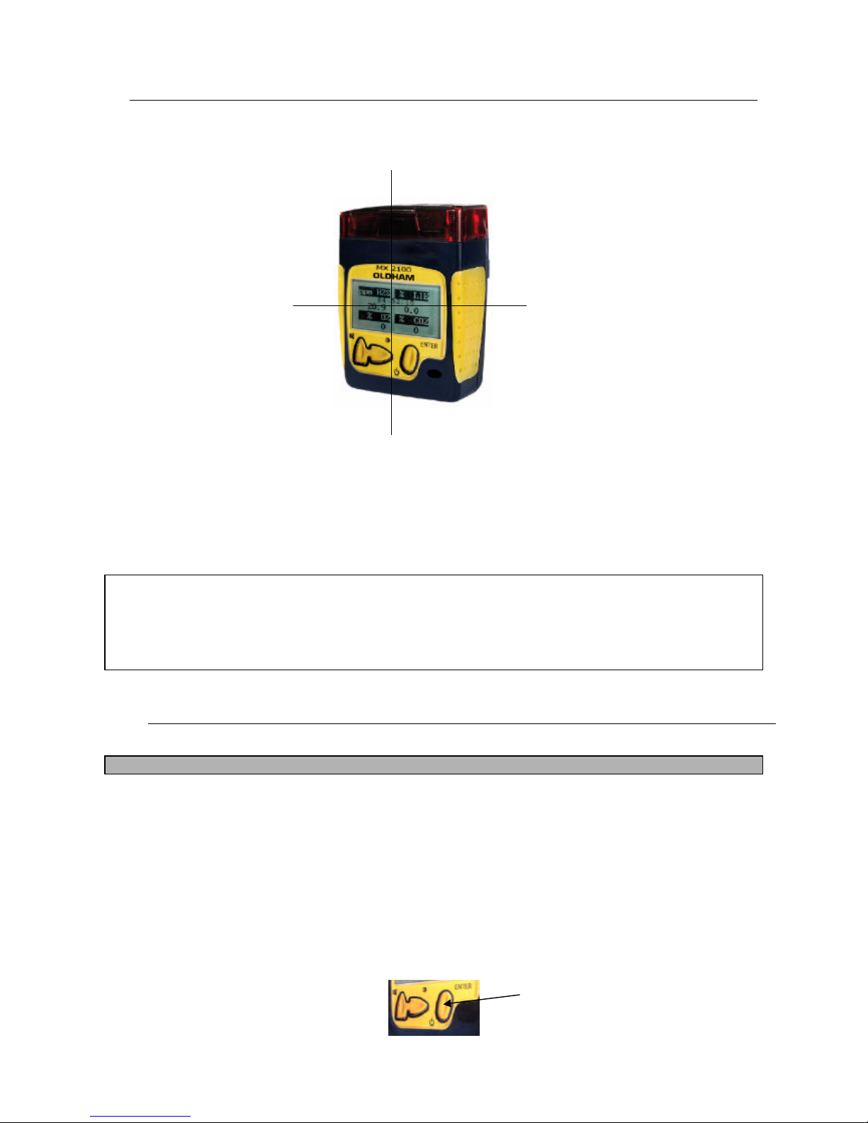
11..
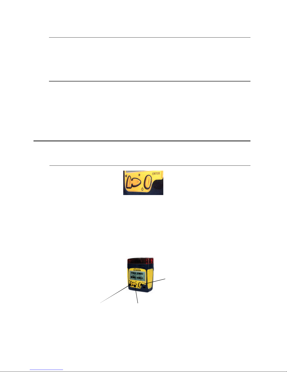
FFUUNNCCTTIIOONNSS ooff kkeeyyss:: aacccceessssiibbllee bbeellooww tthhee ddiissppllaayy uunniitt oonn tthhee
aapppplliiaannccee''ss ffrroonntt ppaanneell
• Switch the appliance ON or OFF.
• Read mode on display unit.
• Acknowledge the gas audio alarm.
• Backlighting of display unit (extinguished automatically after about 15 seconds).
• Scroll through parameters.
• Select menus during utilization phase.
• Access the Maintenance level.
• Validate.
On/Off /Validate
Acknowledge audio alarm
Display unit read mode
Backlighting of display unit
Scroll through parameters
Scroll through menus
Page 10
11
22..
RREEAADDIINNGG MMEEAASSUURREEMMEENNTTSS
The gas content measured by each of the cells "in service" can be consulted on the alphanumeric display unit.
This is divided into four separate areas, each one corresponding to a "measuring channel".
Example:
- A maximum of four measurements can be displayed simu ltaneously.
In each field, the measurement is displayed as follows:
• Measurement, measuring unit and gas symbol
The time is also shown at the bottom of the display unit.
Remark: The display unit can be manually programmed for reading from the front or from the top, depending on how
the appliance is carried by the user (on belt, in pocket, etc.).
This operation is performed by holding down the "acknowledge audio alarm" key for 3 seconds.
If five channels are used, the display in the last position will alternate.
If there are no toxic cells, the Oxygen and Explo. measurements will be displayed at the top of the dial.
33..
SSWWIITTCCHHIINNGG OONN
REMINDER: Before switching on the MX 2100, check that the necessary cells are connected.
When you switch the appliance on, you have a choice of two procedures:
• a standard procedure adopted in most cases,
• a procedure allowing you to select a reference explosive gas, this procedure being useful when checking for
a specific gas (town gas, methane, etc.).
3.1. Switching on in standard mode
• Briefly press the "On/Off/Enter" key.
Data field
second "toxic" channel
Data field
First "toxic" channel
Information field
Oxygen or toxic channel
CO2 or COV, etc.
Data field
"Explo" channel
Page 11

12
• The appliance carries out a visual and audio test phase for a few seconds and indicates:
- the Oldham logo,
- the version of the "appliance" software, date, code and serial number (according to the product version
selected by the customer),
- the preprogrammed values of the alarm thresholds for each measuring channel (according to the product
version selected by the customer),
- measurements currently performed.
Note: When the appliance is operating, a visual and audio signal indicates that the MX 2100 is operating correctly. This
signal can be cancelled or the interval between each signal can be modified, as required.
3.2. Switching on with choice of reference explosive gas
• Hold down the "lighting" or "acknowledge" key.
• Switch on the appliance by pressing the "On/Off/Enter" key.
• Release the key on the two fields.
• The display unit shows the Oldham logo for a few seconds while it performs its self-tests.
• It then displays the list of preprogrammed gases, with the currently selected gas in the dark field.
Choosing a new reference gas:
• Each time you press the "Acknowledge" key, the list scrolls downwards and, each time you press the
"Lighting" key, the list scrolls upwards. Thirty-one reference gases are preprogrammed in the range 0100% LEL (or 0-5% volume CH4). A thirty-second (32) "Autre" (Other) lets you select a gas according to
your specific requirements. The data specific to that gas are entered in the workshop.
• Accept the choice: when the chosen gas is displayed, press the "ENTER" key.
The appliance switches to "Testing" mode, as described in the previous section, before going on to the working phase.
The reference explosive gas is now the gas that was selected.
If you do not validate any gas, after a certain time, the MX 2100 switches to the test phase and to the normal
scanning phase without changing the reference gas, so that the procedure is aborted.
• If the tests are unsatisfactory, the appliance switches to alarm mode (rapid discontinuous audio signal and
flashing alarm light).
The appliance is ready to use.
44..
SSWWIITTCCHHIINNGG OOFFFF
The appliance is switched off by holding down the "On/Off" key for three seconds.
During this time, the countdown "Arrêt 3,2,1" (Stop, 3, 2, 1) is displayed on the display unit, at the bottom of the dial,
before it is switched off.
Page 12

13
When the appliance is switched off, the memorized values (cell adjustment data, alarm thresholds, histogram, etc.) are
not lost.
The theoretical storage time for these values is two years (provided that the main batteries are never discharged).
When the appliance is returned to the workshop, it is useful to recharge the batteries or to print out the exposure
histograms.
55..
DDIISSPPLLAAYY UUNNIITT LLIIGGHHTTIINNGG
Measurements can be read in dark places by pressing the "Lighting" key.
The display unit is then lit up in backlighting mode so the data can be read easily. This lighting is automatically
deactivated after 30 seconds.
The lighting function can be used in dangerous environments, i.e. containing explosive gases as the MX 2100
guarantees intrinsic safety.
The display unit backlighting is automatically activated in case of alarm or fault.
66..
SSCCRROOLLLLIINNGG TTHHRROOUUGGHH MMEEMMOORRIIZZEEDD PPAARRAAMMEETTEERRSS
When the appliance is in normal operating mode, you can consult a series of data on gas measurements and also the
appliance's internal data (battery voltage, date and time).
With the appliance in normal operating mode, press the "lighting" key repeatedly to scroll through the parameters for
each measuring channel.
- Display unit backlighting and date display
- Current location: name (currently used) and time. This line is displayed if the appliance is equipped with
the "roundsman" option. (See section 6.1.)
- Remaining autonomy
- Time
- Indication of minimums detected by each cell
- Indication of maximums detected by each cell
- STEL of each "toxic" channel
- TWA of each "toxic" channel
- The message stating "Entrez le code de maintenance" (Enter maintenance code): to access maintenance
menus, specify the four -figure code with the "Acknowledge" and "Lighting" keys.
- If the code validated is incorrect: return to normal display.
- To quit the list before the end: press the "Acknowledge" key.
Page 13

14
6.1. "Roundsman" function
If the appliance is equipped with the "Roundsman" function (which is optional), a list of names can be preprogrammed
using the COM 2100 software and it can be consulted manually via the keypad.
In the list of parameters, when you display "Localisation courante" (Current location) and the name used, you can then
validate another name, as follows:
- Current location / name,
- Enter,
- Scrolling through preprogrammed list downwards or upwards with keys:
- Enter (to validate the new name),
- Acknowledge (to return to normal mode).
77..
AALLAARRMMSS
- Visual alarms: messages in uncoded mode on the display unit, indicator lights
- Audio alarms: buzzer and vibrator (optional)
7.1 "Gas" alarms
Depending on the programming used and the type of gas, the "gas alarms" can be triggered on exceeding a preset value:
• 2 instantaneous thresholds per channel for Explo, Tox or Oxygen,
• High and low thresholds on Oxygen channel (2 low thresholds on option),
• 1 instantaneous threshold on the katharometric channel,
• Exposure limit (STEL) corresponding to a sliding average over 15 minutes (depending on the country) for
each channel equipped with a toxic gas cell,
• Mean exposure (TWA) corresponding to a sliding average over eight hours for each channel equipped with
a toxic gas cell.
In this way, as soon as the predefined alarm thresholds are exceeded on at least one channel, the MX 2100 triggers an
audio and light signal. The alarm message or messages (FAULT, ALARM, TWA, STEL, min., etc.) and the
measurement value in the corresponding field appear on the display unit.
Common indicators for
gas alarms and faults
Types of alarms:
Alarm 1: two-tone slow
Alarm 2: two-tone fast
Fault: single-tone
Page 14

15
7.2 Fault alarms
Faults can be classified into two categories:
• Faults concerning cells: out of range, worn cell, request for calibration in case of a major deviation during
auto-adjustment. These faults generate individual messages displayed on the relevant quadrant of the
display unit, a visual alarm and a continuous audio alarm.
• Faults concerning the appliance itself (discharged batteries or electronic fault). The corresponding fault
message appears at the bottom of the display unit. It takes priority over all other messages con cerning the
cells.
Examples of information which may be brought to the user's attention
v "Flat batteries"
• The batteries must be charged.
• The remaining autonomy is about 20 minutes after which the appliance will automatically shut down.
This alarm cannot be acknowledged, only the audio signal can be cancelled.
v " > 100% LEL: outside range"
• This concerns only the explosimetric channel.
• In this case:
- The display in the quadrant concerned is frozen,
- it is impossible to acknowledge the continuous audio signal,
- the general alarm indicator lights come on in steady mode.
• Normal operating conditions can be restored by stopping and restarting the MX 2100.
• Caution must be exercised in the area owing to the presence of explosive gases exceeding LEL.
v "Outside range"
• Scale exceeded by 20% in negative direction, with display of negative.
• Scale exceeded by 120% for toxic gas and oxygen.
v "New calibration"
• Automatic adjustment of the zero is impossible owing to, for example, excessive deviation of the zero on
the cell.
• Replace the cell concerned.
7.3 Acknowledging alarms
7.3.1. Acknowledging gas alarms
This does not cancel the gas alarm but only the fast audio signal. When the "Acknowledge" key is pressed:
The fast audio alarm is stopped but the alarm indicator light continues flashing until the measurement is lower than the
programmed alarm threshold. The visual signal is automatically extinguished as soon as the measurement returns within
the defined limits.
A function automatically resetting the audio alarms after a given time if presence of gas persists is available on option.
Page 15

16
7.3.2. Acknowledging fault alarms
It is impossible to acknowledge a fault alarm.
Fault alarms are cleared automatically as soon as the fault has disappeared.
88..
MMEEAASSUURREEMMEENNTTSS
8.1. Display of instantaneous measurements
8.1.1. In "natural diffusion" mode
All the instantaneous measurements regarding gases is displayed in continuous mode.
The display unit is divided into four separate fields (quadrants).
The following information can be read:
• measurement which is displayed continuously,
• the measuring unit preceding the gas symbol.
8.1.2. With electric pumping systems
• Before taking a reading, wait for the measurements to stabilize. They will be either overestimated
(explosive gases) or underestimated (oxygen) during pump ing owing to the movement of air.
• When an electric pump is used, wait a few seconds before reading the measurement. Any fault on the
pumping system will be indicated by an audio alarm and the display unit.
8.1.3. With manual pumping systems
Before taking a reading, wait for the measurements to stabilize. They will be either overestimated (explosive gases) or
underestimated (oxygen) during manual pumping (with bulb) owing to the movement of air and the bleeding of the
system.
8.2. Automatic switching to "0-100% GAS" range
An option provides for automatic switching from the measurement of explosive gases in the "0 -100% LEL" range to the
"0-100% GAS" range when the measurement exceeds 100% LEL for the selected reference gas. This measurement can
only be used on an appliance equipped with a "Explo/Katharo" cell.
8.3. Memorizing histogram measurements
Depending on the version, the MX 2100 can memorize measurements so they can be restored later on a computer.
The "Histogrammes" (Histograms) function can be used to output values and events memorized by MX 2100 during its
operating period to a computer (a workstation, for example). Resetting of the data contained in the histogram memory
can only be performed with a computer. Switching off the MX 2100 has no effect on memorized data.
Page 16

17
8.3.1. Operating principle
To make the best possible use of the data output when histograms are printed, you must understand the operating
principle of data memorization.
Items memorized:
The MX 2100 stores sets of data when it is switched on and then in cyclic mode. Each of these data sets has the same
structure and contains the following:
• the mean measurement of concentrations on each sensor in operation over a preprogrammed duration (one
sampling operation per second);
• the events on each channel:
- resetting,
- fault,
- instantaneous or mean alarms,
- types of maintenance requested (programming, calibration, cell replacement),
- date and time,
- battery in discharged state,
- auto-adjustment request,
- maintenance function request.
Memory capacity:
As the physical memory of the MX 2100 is limited, the number of measurements that can be stored is also limited and,
therefore, so is the operating time.
If the quantity of data to be memorized exceeds the MX 2100 storage capacity, the oldest data are lost. In other words,
the memory freed is used to memorize new data.
Readable items
The appliance calculates a mean value over a one-minute period for each channel in service and for each second. These
averaged data are stored in memory. The MX 2100 serial port can be used to connect:
• a PC type computer to read the measurement mean values.
Data storage time
The data stored by the MX 2100 are stored even if the appliance is not used for a long time (out of service).
99..
PPRRIINNTTIINNGG DDAATTAA ((VVIIAA CCOOMM 22110000))
The data stored in memory can be printed on a printer connected to a computer.
There are two possible cases, as follows.
1) MX 2100 connected directly to a computer by a cord equipped with an infrared link: a "charger or pumping"
module can be used to hold the infrared system on the appliance.
cord
Charger or pumping unit
IR component
Page 17

18
2) MX 2100 integrated in a "Twincall" calibration station which is, itself, connected to a computer and a printer.
IIIIII..
SSPPEECCIIAALL IINNSSTTRRUUCCTTIIOONNSS FFOORR UUSSEE IINN AATTEEXX
EEXXPPLLOOSSIIVVEE AATTMMOOSSPPHHEERREESS
The MX 2100 can be used in explosive atmospheres in Group II surface industries and Group I mines containing
firedamp.
Depending on the type of cells used on the appliance, the MX 2100 covers the following categories:
a) Appliance equipped with any type of cell unit except CO2 infrared unit and MOS unit
- Surface industries: Category 1G, utilization in zones 0, 1 or 2
- Mines containing firedamp: Category M1, utilization for all gas content levels
b) Appliance equipped with any type of cell unit and CO2 inf rared unit and MOS unit
- surface industries: Category 2G, utilization in zones 1 or 2
- Mines containing firedamp: Category M2, utilization below a gas limit value
The following operations are prohibited in explosive atmospheres:
- opening of the appliance: cell cover or rear cover,
- replacement or recharging of batteries,
- link-up with a computer.
When the appliance is recharged using a charger other than that supplied by Oldham, its characteristics must be such
that it does not exceed a voltage of 30 V DC and a current of 30 A.
Non-rechargeable and rechargeable batteries must be replaced with original parts recommended by the manufacturer.
All servicing, adjustment and maintenance operations must be performed by duly approved personnel.
IIVV..
MMAAIINNTTEENNAANNCCEE
IMPORTANT:
The MX 2100 is a safety appliance and, therefore, it must be calibrated at least once a year and according to its
utilization. The user will automatically receive a maintenance reminder every six months.
These operations, explained in this section, must be performed by authorized, qualified personnel only as they
could adversely affect detection safety.
Page 18

19
11..
AAcccceessss ttoo mmaaiinntteennaannccee mmeennuuss oonn MMXX 22110000
With the appliance in operation, menus can be accessed in the following manner:
Scroll through the parameters with this key until a request for an access code appears.
The access code is in four figures. Scroll to each figure with the "lighting" key, select the figure with the
"Acknowledge" key and then validate the access code (given by Oldham) with the "ENTER" key.
The list of available menus is then displayed:
- programming,
- calibration,
- auto-zero,
- date and time,
- exit.
-
1.1 Channel programming menu
This is used to:
• Select the channel to be programmed.
• Switch the selected channel ON or OFF.
• Inform the operator of the type of cell for the measuring range.
• In the case of an explosimetric cell (1), to select the type of reference gas from 31 preselected gases or to
enter the coefficient of a 32nd gas and program instantaneous threshol ds.
• When an oxygen cell is used, to program the "min." and "max." alarm thresholds.
• When a toxic gas cell is used, to program instantaneous thresholds.
• When a katharometric cell is used, to program the low instantaneous threshold.
choose
validate
Page 19

20
LEL France
LEL
Germany
UEL Density
Standard coef.
Range coef.,
'All gases'
German
standard coef.
German coef.,
'All gases'
Ethyl acetate
C4H8O2 2.10% 2.20% 11.50% 3 1.70 1.05 1.62 1.00
Acetone
C3H6O 2.15% 2.50% 13% 2.1 0.00 0.00 0.00 1.05
Acetylene
C2H2 1.50% 2.30% 100% 0.9 0.00 0.00 0.95 0.60
Butadiene
C4H6 1.40% 1.40% 16.30% 1.85 0.00 1.00 0.00 1.00
Butane
C4H10 1.50% 1.40% 8.50% 2 1.91 1.20 2.00 1.25
Butanone
C4H8O
1.80%
1.80%
11.50%
2.5
0.00
1.35
0.00
1.40
Cyclohexanone
1.00% 0.00 2.50
Dimethyl ether
C2H6O 3.00% 2.70% 27.00% 1.6 0.00 0.00 2.10 1.30
Prem.petrol/gasoline
Mixture 1.10% 0.60% ? 6 % 3 à 4 3.15 2.00 4.50 2.80
Ethanol
C2H6O 3.30% 3.10% 19.00% 1.6 1.66 1.05 1.77 1.10
Ethylene
C2H4
2.70%
2.30%
34.00%
0.98
0.00
0.80
0.00
0.95
LPG
Prop+But 1.65% 1.65% ? 9.0 % 1.85 2.30 1.45 2.30 1.45
Gas oil
Mixture 0.60% 0.60% ? 6.0 % > 4 0.00 3.90 5.00 3.10
Natural gas
CH4 5.00% 4.40% 15.00% 0.55 1.05 1.05 1.15 0.75
Hexane
C6H14 1.20% 1.00% 7.40% 3 0.00 0.00 2.50 1.55
Hydrogen+B26
H2
4.00%
4.00%
75.60%
0.069
1.10
0.70
1.10
0.70
Isobutane
C4H10 1.50% 1.30% ? 15 % 2 0.00 1.25 2.25 1.40
Isopropanol
C3H8O
2.15%
2.00%
13.50%
2.1
2.26
1.40
2.40
1.50
Kerosene (JP4)
C10 - C16 0.70% 0.70% 5.00% > 4 5.00 3.15 5.00 3.15
Methane
CH4 5.00% 4.40% 15.00% 0.55 1.00 1.00 1.14 0.75
Methanol
CH3OH
5.50%
5.50%
44.00%
1.1
1.60
1.00
1.60
1.00
Methyl amine
CH3NH2 4.90% 4.20% 20.70% 1.1 2.00 1.25 2.30 1.45
Octane
C8H18
1.00%
0.80%
6.00%
3.9
2.46
1.55
3.00
1.90
Propylene oxide
C3H6O 2.30% 1.90% ? 2 0.00 0.00 0.00 1.90
Ethylene oxide
C2H4O 2.60% 2.60% 100% 1.5 0.00 1.65 0.00 1.65
Pentane
C5H12
1.40%
1.40%
8.00%
2.5
2.10
1.30
2.10
1.30
Propane
C3H8 2.00% 1.70% 9.50% 1.6 1.57 1.00 1.80 1.15
Propylene
C3H6
2.00%
2.00%
11.70%
1.5
0.00
0.95
0.00
0.95
Toluene
C7H8 1.20% 1.10% 7.00% 3.1 2.47 1.55 2.69 1.70
White spirit
Mixture 1.10% 1.10% 6.50% > 2 5.00 3.15 5.00 3.15
Xylene
C8H10 1.00% 1.10% 7.60% 3.7 3.00 1.90 2.75 1.75
(1) List of main preprogrammed gases. Coefficients are given with respect to methane.
Page 20

21
• If the selected gas is "Autre" (Other), a multiplying coefficient must be entered. (See Table 2).
Table 2 contains the coefficients for gases which do not have their coefficients entered in the appliance on a standard
basis.
These coefficients, to be programmed for the "Autres gaz" (Other gases) channel, are calculated with respect to
methane, as the appliance systematically recalculates the values of sensitivity coefficients with respect to that gas.
Table 2: Supplementary sensitivity coefficients to be programmed for the MX 2100 "other gases" channel
Gas Empirical
formula
LEL UEL Vapour
density
Coefficient
/CH4
Benzene C6H6 1.2 % 8.0 % 2.7 2.2
Cyclohexanone (CH2)5CO 1.3 % 9.4 % 3.4 3.2
Premium petrol Mixture 1.3 % 6.0 % > 2 2.1
Ethane C2H6 3.0 % 15.5 % 1.04 1.0
LPG Prop+But 1.65 % ~9.0 % 1.85 1.48
Methylamine CH3NH2 4.9 % 20.7 % 1.1 1.05
Styrene C8H12 1.1 % 8.0 % 3.6 2.5
Octane > 2 3.0
Example of use:
Detection of white spirit with an MX 2100 appliance:
§ Select "Autre gaz" (Other gas) on the explosimetric channel.
§ Program the coefficient = 3.0.
§ Select the standard gas. If it is white spirit, select "Autre" (Other) as the standard gas.
§ Calibrate the appliance in the normal way, specifying the content for the standard gas used.
1.2. Cell calibration menu
This menu is used to regularly calibrate the cells connected to the appliance.
Calibration consists in adjusting the zero of the clean air cell (free of gas which may be detected by the MX 2100) and
adjusting sensitivity with a standard gas of known characteristics (including content, etc.).
1.3. Auto-zero menu
This menu lets you adjust the "zero" of each cell used in the MX 2100 automatically and simultaneously.
Caution: This menu must be used in clean air only.
1.4. Date and time management menu
This menu is used to update the internal calendar and clock of the MX 2100.
These data are used to define time scales, especially when the measurements stored in memory (min., max., STEL and
TWA) are printed out or downloaded to an external microcomputer.
Loss of date and time
The electronic circuits for the date and time are supplied with power by a specific lithium battery when the MX 2100 is
switched off. This battery has an estimated service life of 3 to 5 years. It must be replaced when that period of time has
passed, if the time-keeping is wrong or if the date cannot be stored in memory.
IMPORTANT: This operation is to be performed by OLDHAM or OLDHAM approved personnel only.
Page 21

22
1.5. Exit menu
To return to normal user mode.
22..
AALLAARRMM TTEESSTT WWIITTHH TTEESSTTBBEENNCCHH
The testbench can be used to regularly check the correct operation of the MX 2100.
This system automatically injects standard gases from two cylinders installed in the testbench in order to trigger the
alarms.
The MX 2100 detects the presence of the testbench and indicates the faulty channel or channels according to the test, on
the display panel.
33..
CCAALLIIBBRRAATTIINNGG CCEELLLLSS WWIITTHH CCAALLIIBBRRAATTIINNGG SSTTAATTIIOONN
Calibration of the MX 2100 cells can also be performed using this automatic gas injection system which is managed by
computer and linked to the control devices via the COM2100 software.
Status and check sheets are stored on the computer.
the station is to be used in accordance with the instructions on the front panel (as in the case of the testbench).
VV..
CCOOMM 22110000 SSOOFFTTWWAARREE
COM2100 software ensures the appliance's super vision and maintenance:
- display, in uncoded mode, of measurements and parameters on channels,
- diagnostic assistance in case of failure,
- programming of appliance and measuring channels,
- management of options,
- calibration of channels using automated scrolling menu,
- output of status and check sheets,
- management, display and printout of stored events and measurements,
- protection by password.
The link between the MX 2100 and the PC is made by an infrared port (cord assembly), as shown opposite:
(1) A charger or sampling unit can be used to mechanically hold the IR cord on the appliance.
Insertion of
MX 2100
Follow the indications shown on the front
of the testbench
cord
Charger or pumping unit (1)
IR component
Page 22

23
When the installation operation has been completed and the components are in operation, your working conditions are
extremely user -friendly using the available screens. See a few examples below.
Opening screen
"Fichier" ( Menu) screen
From the "Fichier" (Menu) window, you can open saved files, check and status sheets, and histograms on the computer.
Page 23

24
"Communication" screen
This screen is used to select the port, the communication speed and the language used.
"Fenêtre" (Window) screen
This is used to select the type of screen.
Page 24

25
"Aide" (Help) screen
This provides the user with help in the event of problems with operation, consultation or display.
MX 2100 connection
When the MX 2100 is correctly connected to a computer by an infrared cord, this screen can be used to validate
communication by looking on the "Connect" window.
- Status sheet: to view and save the configuration of the MX 2100 connected.
- Check sheet: to view and save the status of the connected MX 2100, after tests and adjustments.
- Histories: to view and save measurements m ade and stored in memory by the MX 2100.
Page 25

26
VVII..
CCHHAARRGGEERR MMOODDUULLEE
• Connect the charging module to the top of the appliance as shown in the photo below and charge for at least
2 hours 30 minutes for completely discharged batteries.
• This module can be supplied with power by the 230 V AC mains using an adapter unit or with DC power
(12 to 30 V DC).
• Average charging time = 3 hours maximum.
VVIIII..
AACCCCEESSSSOORRIIEESS
REFERENCE DESCRIPTION
6121620 Carrying case
6121621 Leather bag
6123597 Protective case
WLOG210 COM 2100 software kit with IR cord
WCE2100 CHARGER supplied with calibrating pipe and power supply unit
6313797 Electric pump module, SI standard
6327918 Sampling kit for electric pump with telescopic probe
VVIIIIII..
SSPPAARREE PPAARRTTSS
REFERENCE DESCRIPTION
6111174 Lithium battery
6311081 NiMH rechargeable battery pack
6313787 Co cell
6313788 H2S cell
6313780 O2 cell (2 years)
6313792 Explo. cell, 0-100% LEL
6313817 O2 cell (1 year)
6313818 CO2 cell (0-5%)
6313812 COCL2 cell
6313802 NO cell
6313801 NO2 cell, 30 ppm
6313799 NH3 cell, 100 ppm
6313809 Cl2 cell, 10 ppm
6313804 HCl cell, 30 ppm
6313805 HCN cell, 30 ppm
6313800 NH3 cell, 1,000 ppm
6313807 O3 cell, 1 ppm
6313803 H2 cell
6313806 HF cell
6313615 H2S cell, 30 ppm , special for hydrocarbons
6313808 SiH4 cell
6313810 PH3 cell, 1 ppm
6313811 AsH3 cell, 1 ppm
Note: This list is not exhaustive and may be modified.
Cells must be stored in a cool place (5°C).
Page 26

27
IIXX..
TTEECCHHNNIICCAALL CCHHAARRAACCTTEERRIISSTTIICCSS
11..
MMXX 22110000 aapppplliiaannccee
Manufacturer: OLDHAM
Function: Multi-risk gas detector
Type: MX 21OO
Configuration:
• One to four cells (explosimetric, electrochemical, semiconductor, infrared (CO2) or katharometric cells)
Gases detected: Explosive gases, toxic gases and oxygen
Measurement: continuous on all cells in operation
Cell:
• Intelligent, precalibrated interchangeable unit
• automatic recognition by the appliance by means of EEPROM
Display unit:
• Graphic LCD
• Messages in uncoded mode, with backlighting
Display lighting: with time switch
Switching of explosimetric ranges
• Automatic, from "% Gas" scale to "% Volume" scale
Cell fault
• Indication by indicator light
• Message in uncoded mode
• Corresponding display "frozen". Other channels operational
• Continuous general audio and visual alarm
Battery fault
• Display in uncoded mode
• Continuous general audio and visual alarm
Operating check
• Automatic calibration on request (optional)
• Self-test on power -up
• Audio and visual signal every 2 minutes (factory)
• Display of measured values in uncoded mode
Alarms
• Explosimetry: 2 adjustable instantaneous thresholds in 0-60 % LEL range
• Oxygen metering: two adjustable instantaneous thresholds over the cell's whole measuring scale (over -
oxygenation and under -oxygenation)
• Toxic gas metering (by cell)
• Two adjustable instantaneous thresholds over the whol e range:
- one TWA threshold
- one STEL threshold
Page 27

28
Alarm signals
• General audio and visual alarm (display unit, indicator light)
• Display in uncoded mode of the fault or alarm for the channel concerned
Outputs (optional)
• RS232 link by infrared
• on PC, maintenance and supervision software, EXCEL database
Ancillary software packages
• Maintenance software COM 2100 and 2100S
Power supply
• 3 AAA alkaline batteries
• or coated NiMH rechargeable battery pack
Battery autonomy
• 14 hours in standard operation
• 8 hours with pump
Charging time:
• 3 hours
Sealing: >= IP20 (IP66 following the catalogue)
Weight: 350 g
Dimensions: 110 high, 80 long, 45 deep (mm)
CE marking:
Marking in accordance with Electromagnetic Compatibility Directive 89/336/CEE: compliance with standard
EN 50270.
Explosive atmospheres ATEX 94/9/CE:
Marking in accordance with Explosive Atmospheres Directive ATEX 94/9/CE:
On MX 2100:
OLDHAM Arras
CE 0080
MX2100
II 1G II 2G I M1 I M2
EEx ia IIC T4 EEx ia I
EEx ia d IIC T4 EEx ia d I
INERIS 03ATEX0216
Do not open in explosive atmosphere
Serial number
Year of manufacture
On pump unit BP2100:
OLDHAM Arras
CE 0080
BP2100
II 1G I M1
EEx ia IIC T4 EEx ia I
INERIS 03ATEX0216
Do not open in explosive atmosphere
Serial number
Year of manufacture
Page 28

29
Page 29

30
22..
MMeeaassuurriinngg cceellllss ((nnoonn--eexxhhaauussttiivvee lliisstt))
Explo. O2 2 yrs C12 CO H2 H2S HCl HCN NH3 NO NO2 SO2 CO2 Katharo.
Standard range (1) 100%
LEL
30% 10 1000 2000 100 30 10 100 300 30 30 5% 100% vol
Accuracy (2) 1 0.1 0.03 1 1 1 0.1 0.1 1 1 0.1 1 0.1 1
Repeatability (3) 1 1 2 1 1 1 2 2 2 1 1 1
Deviation of zero (4) < 0.5 % 0.5 0.5 0.5 0.5 0.5 0.5 0.5 1 0.5 0.5 0.5 0.5
Response time (5) < 20 < 20 < 60 < 30 <70 < 80 < 90 < 60 < 60 < 30 < 30 < 25 < 30 < 20
Temperature (6) -20+75 -20+40 -20+40 -20+40 -5+40 -20+50 -20+50 -20+50 -30+50 -20+50 -20+50 -20+50 -10+40 10+40
Service life (7) > 60 28 24 36 24 36 24 24 24 36 24 36 60 60
1 - in ppm unless otherwise specified 4 - per month as % of scale
methane reference gas for Explo. 5 - in seconds at 90% of final value
2 - 20% absolute value 6 - in °C without display unit
(same unit as range) 7 - average noted per month
3 - as % of signal read 12-month guarantee
Page 30

Page 31

32
OLDHAM ITALIA S.
R.L.
Italia
' (39) 011 38 013 71
7 (39) 011 38 066 13
paolo.pozzato@oldham.it
 Loading...