

Page 1
1
WARNING
This manual, including the warnings and cautions inside, must be read and followed carefully by all
persons who use or maintain this product, including those who have any responsibility involving its
selection, application, service, or repair.
This cap lamp system will perform as designed only if used and maintained according to the
instructions, otherwise it could fail to perform as designed and persons who rely on this product could
sustain serious personal injury or death.
D
D
L
L
9
9 //
D
D
L
L
1
1
6
6
CAP LAM
P SYSTE
M
INSTRUCTION
MANUAL
NO COMPROMISE
DL9:
Epsilon07ATEX2151/2: Ex I M2 Ex I IEC62013-1 Ta = 0
o
C to +40oC
DL16: Epsilon07ATEX2151/2: Ex I M2 Ex I IEC62013-1 Ta = 0
o
C to +40oC
IECEx ITS 08.0019: Ex I Ta = 0
o
C to +40oC
Page 2
2
DDLL99 // DDLL1166 CCAAPP LLAAMMPP SSYYSSTTEEMM
TABLE OF CONTENTS
Important p3
General description p3
Preparation for use p3
Battery charging p3
Cap lamp system p4
Battery Storage p4
Replacing battery p4
Removing cable from battery p4
Replacing battery cover p4
Using DL9/DL16 cap lamp systems p4
Repairing headpiece p4
Replacing cable p5
Replacing reflector p5
Replacing circuit board p5
Reassembling bezel ring p6
Replacing the lock barrel p6
DL9/DL16 diagram – Item list p7
Parts diagram p8
Troubleshooting p9
Certification, equipment marking and instructions for p10
compliance with ATEX standards:-
Use of Equipment p11
Special Conditions for Safe Use p11
Page 3
3
IMPORTANT
Pay close attention to Warnings and Cautions in
this manual.
A WARNING describes a condition that may
cause severe personal injury or death if allowed to
happen.
A CAUTION describes a condition that may cause
moderate injury or property damage if allowed to
happen.
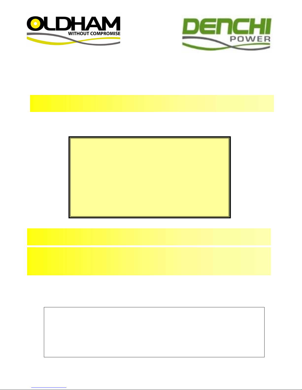
GENERAL DESCRIPTION
The DL cap lamp systems consists of a cap
mounted headpiece powered by a Li Ion battery.
The basis of the headpiece in which some of the
internal connections are integral is as follows:
A selector switch is incorporated, which can
switch on either the main LED light source or the
small emergency LED. The reflector fits over the
small LED and has a rubber gasket around the
rim to seal against the headpiece lens.
PREPARING THE DL9/DL16 CAP LAMP FOR
FIRST TIME USE
The battery is packaged separately to the lamptop
and needs to be connected before use.
Tool kit required is M614830
NOTE: THE BATTERY IS TRANSPORTED IN A
PARTIALLY CHARGED CONDITION - EVERY
BATTERY MUST BE FULLY CHARGED
BEFORE FIRST USE.
Remove the battery from the shipping box and
check for damage. The battery is supplied with
the encapsulated fuse fitted, terminal nuts and
washers.
Remove the nut and washer from the positive end
of the fuse (marked +). Place the ring terminal of
the red wire onto the terminal post, replace the
spring washer and nut, and tighten to 0.5Nm.
Remove the nut and washer from the negative
terminal (not connected to the fuse) and place the
ring terminal of the black wire onto the terminal
post, replace the spring washer and nut, and
tighten down to 0.5Nm.
Hook the cable exit end of the battery cover onto
the battery.
Check that the cables are not trapped under the
edge of the cover then press down into position.
Secure the cover in place with the clip and M4
mushroom head socket screw.
Battery charging
WARNING
Li Ion batteries must only be charged on a
specific charger with a Li Ion charge profile. If
the battery is charged on a standard GT
caplamp charger the battery will be damaged.
For charger information and how to convert
existing charger software please consult the
Caplamp Charger Manual.
Every battery must be charged before it is used
for the first time.
Never discharge completely!
IMPORTANT NOTE:
The L16 battery is supplied with a factory fitted
“OCBL-T” fuse (M455323), required for
protection of the internal battery circuitry.
Use of any other fuse type could result in
damage and will invalidate any warranty claim.
Page 4
4
Charging before first use:
1. Allow the battery to remain on charge for 24
hours.
2. After a working shift, the battery should be
placed on the charger, following the
instructions included with the charger, and left
to charge. The charger automatically
switches off when the battery is completely
charged
3. If cap lamp needs cleaning, use a mild
detergent and wipe. Do not submerge in
water.
Battery Storage
All stored batteries should be given a 24-hour
boost charge 3 months after receipt and thereafter
at 6-monthly intervals until use, where they should
again be fully charged before being placed into
regular service.
Recommended storage temperature: 0oC to 27oC.
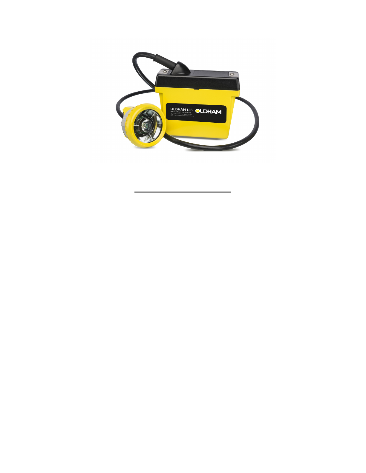
Replacing battery
1. Remove one M4 button head socket screw
from the end clamp holding the cover as
shown.
2. Un-clip the clamp and slide off the cover to
cable end.
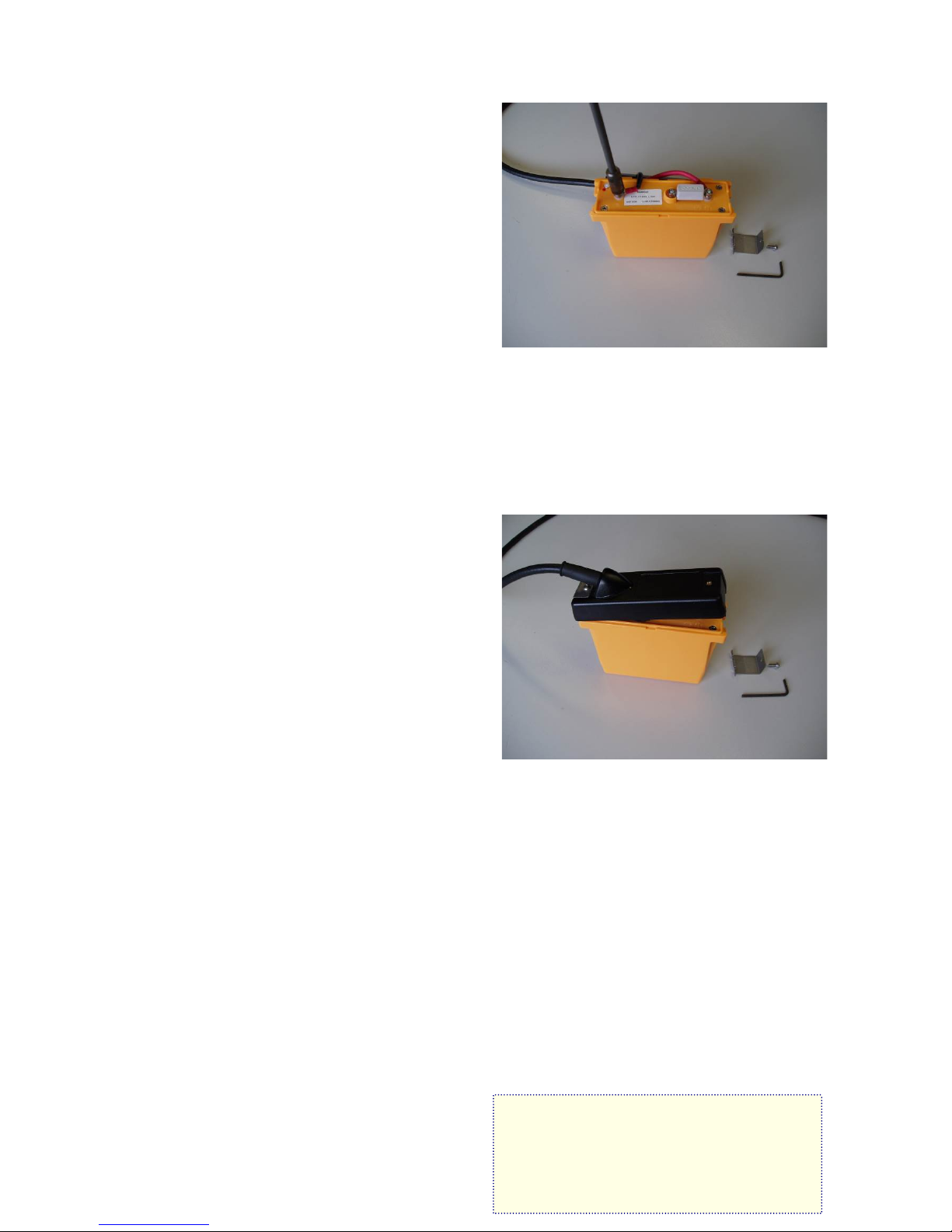
3. Remove the positive cable lead (red)
4. Remove the fuse
5. Remove the negative lead (black)
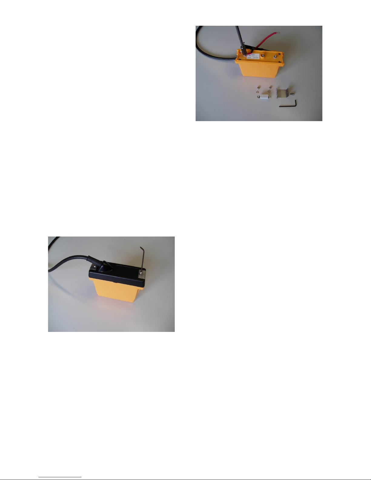
Replacing battery cover
1. Replace the fuse; fit the nuts to hold the fuse
in place
2. Connect the red cable to the positive battery
terminal.
3. Connect the black cable to the negative
battery terminal to ensure correct polarity.
4. Tighten the cable leads down with terminal
nuts to 0.5Nm.
5. Replace the battery cover.
Note:
Ensure that the cable leads lie properly on the
battery top without being trapped or pinched.
USING THE DL9/DL16 CAP LAMP SYSTEM
The DL headpiece is made up of the lamphousing which contains the following parts:
- Bezel (ring)
- Lens (glass)
- Gasket
- Reflector
- Main LED
- Secondary LED
- Circuit board and switch
The on-off-on switch knob is located on the
headpiece. The down position operates the main
LED and up position the secondary LED.
Repairing the headpiece
TOOLS:
G & D type spares and tools kit – M614830
D type Headpiece fastening & cable lock kit M259683
The switch should be placed in the off position
and the battery fuse removed (see section “cap
lamp system”) before disassembly of the
headpiece.
Page 5

5
Replacing Cable
1. Remove the cable from the battery terminals.
2. Cut the cable tie around the cable under the
battery cover and pull the cable out from the
battery cover gland.
3. Unscrew the M3 socket head mushroom
screw from the headpiece cable lock.
4. Use a small screw driver to “flick” the cable
lock off the retaining boss. Take care not to
lose the o-ring under the boss as this is
required for reassembly.
5. Replace the mushroom head socket
screw. This is important to ensure the
circuit board support in the headpiece
does not become loose.
6. Hold the lens glass down while unscrewing
the bezel ring.
7. Remove the lens glass and reflector.
8. Unscrew the 2 off M3 slotted screws.
9. Remove the cable
10. To replace the cable reverse the above
procedure.
Note:- Always ensure that one screw is fixed
into the positive cable terminal or the cable
lock. This ensures the circuit board support
does fall out of position
Replacing the reflector
1. Remove the bezel ring and lens.
2. Remove the reflector
3. Remove gasket around reflector.
4. Place the gasket around the new reflector.
The reflector is located by two projections
which fit either side of the main LED; the hole
in the reflector goes over the secondary LED.
The bezel ring should be screwed down
firmly while holding the glass down with your
thumb.
5. Reassemble the lens and bezel ring (see
“Reassembling the bezel ring”).
Replacing the circuit board
The circuit board can be replaced in the event of
damage to the switch or electronic failure of the
board. This procedure should be carried out by a
person with experience of soldering on small
circuit boards.
1. Remove the cable as described above
2. De-solder the wire connections to the LED at
the circuit board.
3. Carefully bend the cables away from the
circuit board.
4. Use an open ended spanner M204942 to
remove the nut securing the switch. Remove
the washer and rubber backed sealing
washer.
5. Pull the old circuit board out from the front of
the main housing.
6. Put a 10mm spacer in the positive hole
before replacing the board.
7. Replace the circuit board, pull in the threaded
switch boss to ensure it is fully located in the
socket at the back of the headpiece housing.
8. Replace the sealing washer and nut, tighten
with the open ended spanner.
9. Re-solder the wires from the main LED.
10. Replace the cable and reassemble the
reflector, lens and bezel ring.
Page 6

6
Reassembling the bezel ring
1. When the lens is in position over the
reflector, the bezel ring is screwed onto the
headpiece housing, and locked in position by
the stainless steel cable lock.
2. Ensure the cut-outs in the bezel ring line up
with the cable lock.
3. Hook the cable lock into the slot under the
cap hook support. Press down so the cable is
in position, replace the o-ring and then clip
over the boss on the side of the headpiece.
4. Secure with M3x10 mushroom-head screw.
Replacing the lock barrel
If the lock barrel is damaged it may become
difficult to connect the lamp to the charger. In this
case, the lock barrel must be replaced (M259983
– lock contact spares kit).
1. Undo the M4 lock nut and remove the dome-
head screw that runs through the charging
contact housing.
2. The metal cap-clip can be lifted off and set to
one side (take care not to lose the spring clip).
3. Remove the lock barrel and ensure that the
charging contact housing is clear of any
debris before inserting the replacement lock
barrel.
4. Holding the lock spring in position, refit the
cap-clip cover, insert the dome-head screw
and re-tighten the M4 lock nut.
Page 7

7
DL9/DL16 Expanded Diagram, Tools and Spare Parts List
200004 (M271351)
DL9 caplamp (complete)
200000 (M261551)
DL16 caplamp (complete)
203006 (M456623)
L9 Type Li-Ion 12Ah battery
203000 (M456323)
L16 Type Li-Ion 24h battery
201000 (M261951)
D-type Lamptop complete
(with cable and battery cover)
201526 (M259121X)
Bezel ring (D-type)
201504 (M200131X)
Glass lens
201508 (M200411X)
Sealing channel
201527 (M259127X)
Reflector (D-type)
201529 (M259383)
LED CC circuit board
201540 (M260116)
Cable 1.6m (D-type)
203500 (M455323X)
Fuse (type OCBL-T)
201536 (M259683)
D-Type Headpiece Fastening & Cable Lock kit
201524 (M205083)
D and G Cable Terminal Spares kit
201520 (M204683)
D and G Lock Contact Spares kit
201521 (M204783)
D and G Cap-clip Spares kit
201545 (M455045)
Plastic Battery Cover (complete)
Clip for standard cover
Screw for plastic cover
Cable gland
Cable tie
206008 (M614830)
Small tools and spares kit, suitable for all “G” and
“D” type lamps comprising :-
Cable outlet gland key
Allen key for headpiece lock pin
Insulated screwdriver
Spring screwdriver
Spanner for T-type battery terminal nuts
Spanner for L16 battery terminal nuts
Spanner for D-type switch
Two “OCBL” battery fuses
Note: Only certain replacement items above may
be purchased individually. All others, as noted
above, must be purchased in kit form as this
ensures that other associated parts are also
available for replacement at the same time.
Page 8

8
Page 9

9
TROUBLESHOOTING
PROBLEM
CAUSE
LED is dim or fails to light
1) Both LED’s are dim / fail to light
2) Main LED is dim / fails to light
1. Loose connections:
a. Check the connections on the top of the battery to
make sure they are tight.
b. Check the headpiece terminals and the electrical
connections inside the headpiece in the same manner
as those on the battery.
2. Loose connections:
a. Gently wiggle or pry each connection on top of the
battery to make sure it is tight and working properly.
b. Check the cables for broken conductors by twisting or
pulling it at various points along its length.
c. Check the headpiece terminals and the electrical
connections inside the headpiece in the same manner
as those on the battery.
d. Make sure the bulb is secure and making good
contact.
e. If the light flickers or dims when any of the preceding
items are being checked, that item should be repaired
or replaced.
Battery appears “dead” and will not operate a. Check that the fuse has not blown
b. Check the cross volts of the battery, if no voltage is
recorded the battery has been over discharged and
must be recovered on a nursery charger.
c. Detach the battery from the headpiece and reconnect
to the nursery charger via the ring terminals, red
positive+ and black negative- , leave on charge for 8
hours before reconnecting to the lamp top and putting
back on the normal charger for 24 hours.
Battery capacity a. The L9 battery is designed for 10 hour operation, while
the L16 battery will operate a 12+ hour shift. Failure to
achieve this is probably due to a high resistant joint in
the circuit.
b. Check Headpiece charging connections
c. Check charger.
d. Check battery connections.
IMPORTANT : ALWAYS RECHARGE THE LAMP AFTER USE.
ENSURE THAT ONLY CHARGERS WITH THE
CORRECT LI-ION CHARGE PROFILE ARE USED.
Page 10

10
Certification, equipment marking and instructions for
compliance with ATEX standards:-
The DL range of cap lamps are certified for use in Mines where potentially explosive atmospheres
may exist. The lamps are suitable for M2 Mining applications.
Certification codes are:-
DL9: Epsilon07ATEX2151/2: Ex I M2 Ex I IEC62013-1 Ta = 0oC to +40oC
DL16: Epsilon07ATEX2151/2: Ex I M2 Ex I IEC62013-1 Ta = 0oC to +40oC
IECEx ITS 08.0019: Ex I Ta = 0oC to +40oC
Type:- DPL9 / DPL16
Lamp Type Reference:-
The lamps can be assembled in a variety of combinations to satisfy customer requirements. The
assembly combination is stated on the certification label and this combination should not be
changed without consultation with Denchi Power Ltd., Caithness, Scotland.
The type code sequence is as below:-
1 2 3
Lamptop type Battery Cover type Battery type
D Standard P Plastic Cover L9 Li Ion Battery
L Hand Lamp L16 Li Ion Battery
R Remote Take Off
1 2 3
Sample type code:- D P L16
Page 11

11
Use of equipment:-
The user must ensure that the lamp supplied meets the safety standard required for the Zoned
area:-
1. This equipment must only be used in a Category M2 zone without undertaking a full risk
assessment for mine rescue use.
2. Check that the operating temperature range is in the range 0oC to +40oC for Mining.
3. The lamp must not be disassembled in a hazardous area.
4. The lamp must not be charged in a hazardous area.
5. The battery casings are manufactured from polycarbonate and ABS with nitrile rubber
seals. The performance of these materials, with respect to attack by aggressive
substances that may be present in the hazardous area, shall be taken into account before
the equipment is used.
6. Plastic surfaces may cause propagating brush discharges. Propagating brush discharges
are caused by non-conducting fluid flow over a non-conducting plastic surface. The cap
lights shall not be used in areas where a high fluid flow over the plastic surfaces may occur
(for example in the case of a ruptured process pipe or compressed air pipe).
Special Conditions for Safe Use:
There are no special conditions stipulated within the certification.
Denchi Power Ltd.
Denchi House, Thurso Business Park,
Thurso, Caithness, KW147XW
URL: www.oldhamcaplamps.com
Email: enquiries@denchipower.com
Tel.: +44 (0)1847 808000
August 2016
 Loading...