

Page 1
User manual
CTX 300
Analogic Gas Detector
Part Number: NP300GB
Revision: K.1
The Fixed Gas Detection Experts
Page 2

2
CTX 300
User manual
Copyright 2015 by Oldham S.A.S.
April 2015
All rights reserved. No reproduction of all or part of this document, in any
form, is permitted without the written consent of Oldham S.A.S.
All information provided in this document is accurate to the best of our
knowledge.
As a result of continuous research and development, the specifications of
this product may be changed without prior notice.
Oldham S.A.S
Rue Orfila
Z.I. Est – CS 20417
F – 62027 ARRAS Cedex
Tel : +33 (0)3 21 60 80 80
Fax: +33 (0)3 21 60 80 00
Page 3

Contents
3
Contents
Chapter 1 | General Information .............................................. 5
User Manual ............................................................................................... 5
Symbols used ............................................................................................. 5
Safety instructions ...................................................................................... 6
Important information ................................................................................. 6
Liability limits .............................................................................................. 7
Chapter 2 | Introduction ........................................................... 9
General Information ................................................................................... 9
Composition ............................................................................................. 10
Chapter 3 | Installation and connection ................................ 11
Installing the detectors ............................................................................. 11
Electrical connections .............................................................................. 13
Chapter 4 | Powering up and use .......................................... 19
Powering up ............................................................................................. 19
4-20 mA analog output ............................................................................. 20
Chapter 5 | Maintenance ........................................................ 21
Calibration ................................................................................................ 21
Replacing a sensor .................................................................................. 35
Disposal .................................................................................................... 35
Chapter 6 | Spare parts .......................................................... 37
CTX/COX 300 toxic or oxygen sensors ................................................... 37
CSC 300 semiconductor sensors............................................................. 40
CTX 300 – CO2 sensors ........................................................................... 41
Chapter 7 | Certification ......................................................... 43
Page 4

4
CTX 300
User manual
Chapter 8 Technical specifications ....................................... 47
Chapter 9 | Annex ................................................................... 51
Wiring specification .................................................................................. 51
Indications for calibrating the CTX 300 SC .............................................. 53
CTX 300 overview .................................................................................... 54
Page 5

1 – General information
5
Icon
Significance
This symbol indicates useful additional information.
This symbol indicates:
This equipment must be connected to ground.
This symbol indicates:
Protective earth terminal. A cable of the adequate diameter must be
connected to ground and to the terminal having this symbol.
|
Chapter 1 | General Information
User Manual
The instructions given in this manual must be read thoroughly before installation and
start-up, particularly those concerning the points related to the safety of the end-user.
This user manual must be made available to every person involved in the activation,
use, maintenance, and repair of the unit. The information, technical data, and diagrams
contained in this manual are based on the information that is available at a given time.
In case of doubt, contact Oldham for additional information.
The aim of this manual is to supply simple and accurate information to the user.
Oldham cannot be held liable for any misinterpretations in the reading of this manual.
In spite of our efforts to produce an error-free manual, it may nonetheless contain
some unintentional technical inaccuracies.
In the client’s interest, Oldham reserves the right to modify the technical characteristics
of its equipment to increase their performance without prior notice. The present
instructions and their content are the inalienable property of Oldham.
Symbols used
Page 6
6
CTX 300
User manual
This symbol indicates:
You must refer to the instructions.
This symbol indicates:
Warning! In the present mode of use, failure to adhere to the
instructions preceded by this symbol can result in a risk of electric
shock and/or death.
European Union (and EEA) only. This symbol indicates that this product
must not be discarded with household waste, as per the EEA directive
(2002/96/EC) and your own national regulations.
This product must be disposed of at a collection point that is reserved for
this purpose, for example, an official site for the collection of electrical and
electronic equipment (EEE) in view of their recycling, or a point of
exchange for authorized products that is accessible when you acquire a
new product of the same type.
Any deviation as regards these recommendations for the disposal of this
type of waste can have negative effects on the environment and public
health, as these electric and electronic products generally contain
substances that can be dangerous. Your full cooperation in the proper
disposal of this product promotes a better use of natural resources.
Safety instructions
The installation and electrical connections must be carried out by qualified
personnel according to the instructions of the manufacturer and the
standards of the competent authorities.
Failure to adhere to the instructions can have serious consequences on the
safety of persons. Please be extremely rigorous as regards electricity and
assembly (coupling, network connections).
Labels intended to remind you of the principal precautions of use have been placed on
the unit in the form of pictograms. These labels are considered an integral part of the
unit. If a label falls off or becomes illegible, please ensure it is replaced. The
significance of the labels is detailed below.
Important information
The modification of the material and the use of parts of an unspecified origin shall
entail the cancellation of any form of warranty.
The use of the unit has been projected for the applications specified in the technical
characteristics. Exceeding the indicated values cannot in any case be authorized.
Page 7

1 – General information
7
Liability limits
Neither Oldham nor any other associated company under any circumstances can be
held liable for any damage, including, without limitations, damages for loss or
interruption of manufacture, loss of information, defect of the MX 43 control unit,
injuries, loss of time, financial or material loss, or any direct or indirect consequence of
loss occurring in the context of the use or impossibility of use of the product, even in
the event that Oldham has been informed of such damage.
Page 8

8
CTX 300
User manual
Page 9

2 - Introduction
9
Chapter 2 | Introduction
General Information
CTX300 gas detectors are designed to measure toxic gases or vapors and oxygen.
With robust materials, a specifically-adapted design, appropriate accessories,
stainless bolts and a polyamide case (IP54), CTX 300 detectors are designed to
withstand the roughest conditions.
Figure 1: overview of a CTX 300 with display (left) and without display (right).
Page 10

10
CTX 300
User manual
Composition
Sensor type
CTX 300
Toxic
Oxygen
Semiconductor
CO2
Gases
detected
Common toxic
gases detected.
Oxygen.
- Combustible
gas.
- Solvents.
- Some
Freons.
CO2.
Detection
method
Electrochemical
sensors (1).
Electrochemical
sensor.
Semiconductor
sensor.
Infrared
absorption.
Type of sensor
pack
Pre-calibrated
removable
sensor pack
(2).
Pre-calibrated
removable
sensor pack:
0-30% scale or
0-100%
volume.
Removable
sensor pack,
not precalibrated.
Removable
sensor pack
Infrared
column, not
pre-calibrated.
Options
With display.
With display.
Certification
None.
None
None
None
(1) Specific to each gas.
(2) Choice between several scales.
Page 11

3 - Installation and connection
11
Chapter 3 | Installation and connection
Installing the detectors
Layout
While the measuring sensor is always located on the underside of the detector, several
factors determine where the detector should be located:
■ If the gas being measured is lighter than the air, place the detector near the ceiling.
■ If the gas is heavier than the air (CO
close to the floor.
■ Near offtake points.
■ Generally, in locations where gas may accumulate, taking into consideration both:
- The effects of temperature;
- The outside winds direction.
and Freons, for example) place the detector
2
Determining the best sensor location
Factors to consider when determining the best placement for the detector are:
■ Potential sources for vapor and gas emissions.
■ Characteristics of gases and vapors (density).
■ Air circulation:
- Inside: mechanical or natural ventilation.
- Outside: wind direction and velocity.
■ Effects of temperature.
■ Local constraints (air flow, water splash, etc.).
Detectors should always be located in an easily accessible location for maintenance
purposes.
Special accessories may be necessary to protect the equipment against any liquid
projectiles, dust, direct sunlight or low temperatures in the area.
Page 12
12
CTX 300
User manual
Mechanical installation
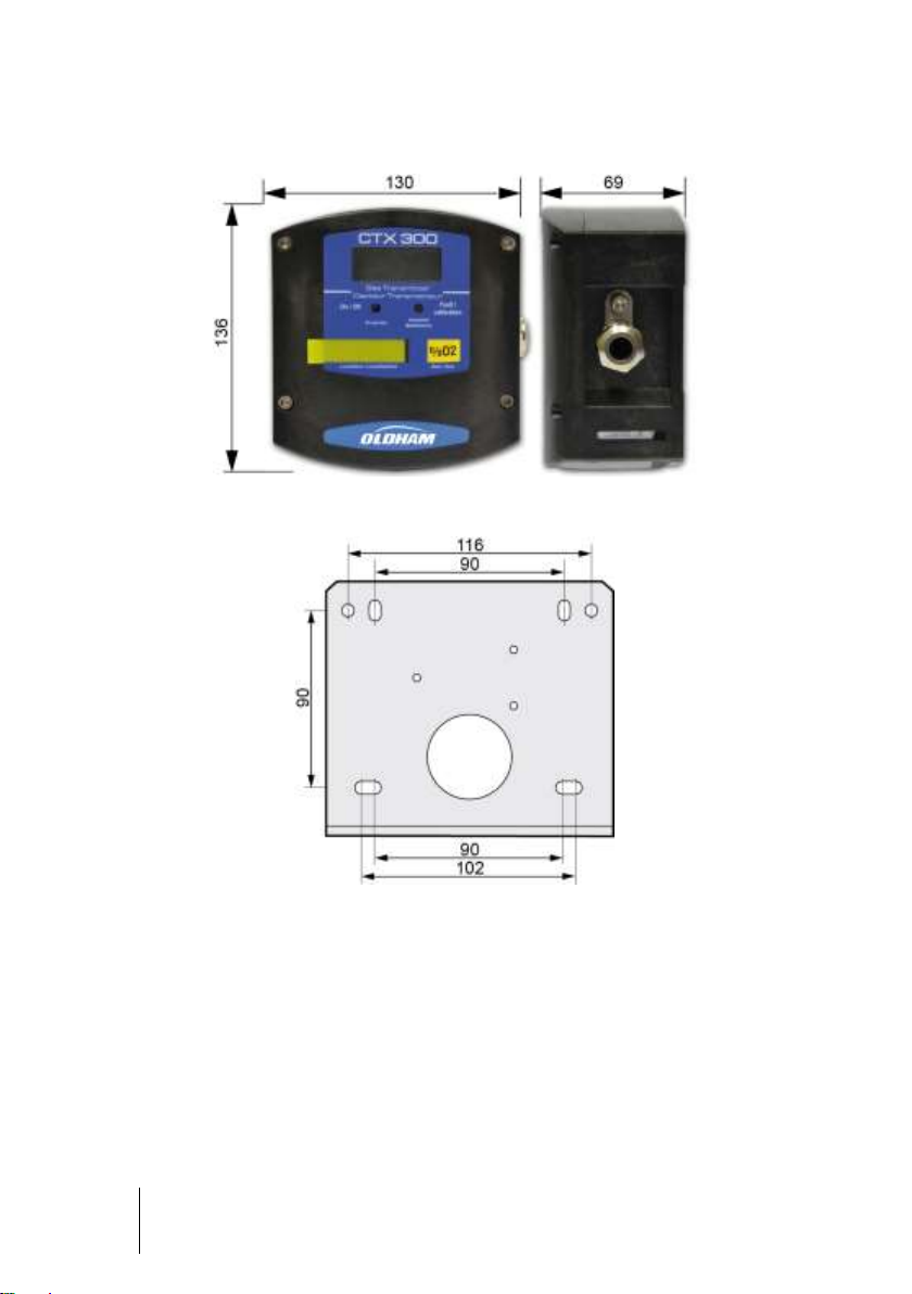
Figure 2: overall dimensions of the CTX 300.
Figure 3: drilling diagram for wall mounting (view of the side flatten onto the ceiling).
Page 13
3 - Installation and connection
13
Ref.
Qty
Description
Code
Material
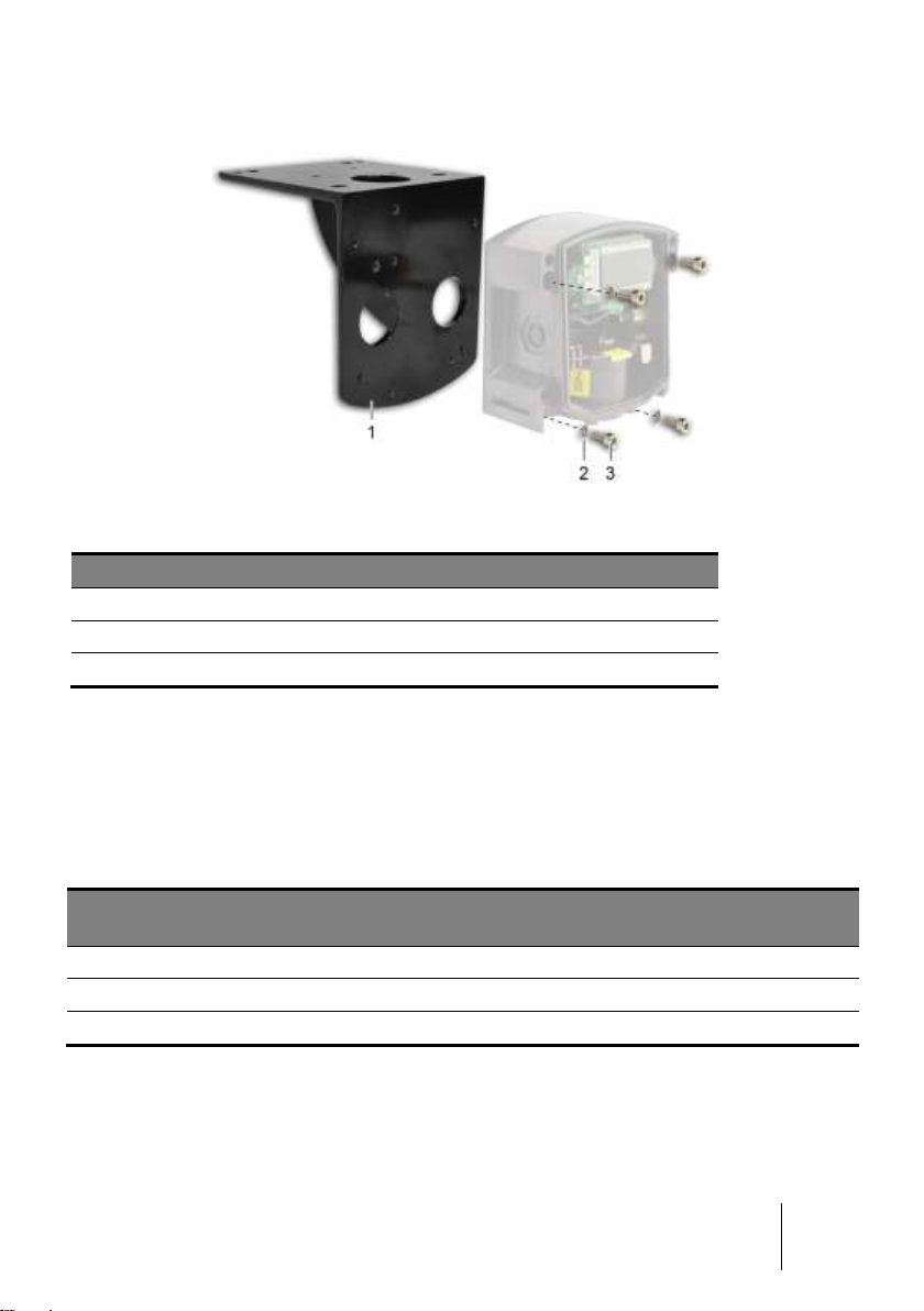
1 1 Brace
6132380
Stainless
2 4 Washer A25 ACCD
6905518
Stainless
3 4 Screw CHC LI2
6902218
Stainless
Wire
CTX 300 (TOX/OX)
with display
CTX 300 (TOX/OX)
without display
CTX 300 SC/CO2
without display
Output signal
4-20 mA
4-20 mA
4-20 mA
Active wires 3 2
3
Cable entry
1 x 6-11 mm
1 x 6-11 mm
1 x 6-11 mm
Figure 4: ceiling mounting with a brace. The fixing drawing is identical to this of the wall
mount.
Electrical connections
Wiring specifications
If needed, consult the grounding instructions for Oldham instruments and related
connection materials in Annex 1.
Connections for the various types of sensors
Page 14
14
CTX 300
User manual
Connection of a 3-wire sensor to an Oldham control unit
Wire
Terminal number
(+) V DC power supply:
3
(-) V DC power supply (masse 0 V):
2
Output signal:
1
Wire
Terminal number
(+) V DC power supply:
3
Output signal:
1
Control unit
Detector
Control unit
Detector
+24 VDC
Signal
+24 VDC
0V
Signal
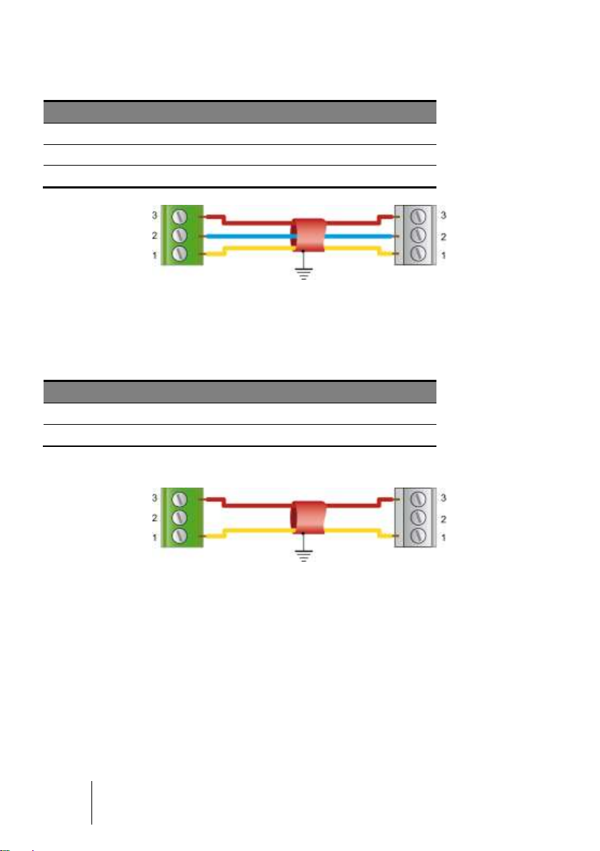
Figure 5: connection of a 3-wire sensor to an Oldham control unit.
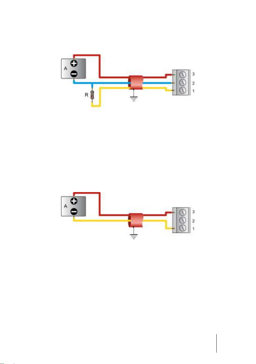
Connection of a 2-wire sensor to an Oldham control unit
Both wires are the 4-20 mA 2-wire loop.
Figure 6: connection of a 2-wire sensor to an Oldham control unit.
Page 15
3 - Installation and connection
15
Other control
unit
Detector
+24 VDC
0V
Signal
Other control
unit
Detector
+24 VDC
Signal
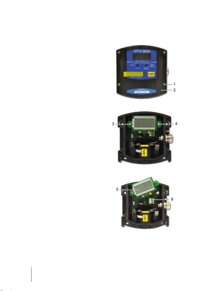
Connection of a 3-wire CTX300 sensor to a non-OLDHAM control unit with an
internal power supply
Figure 7: Connection of a 3-wire CTX300 sensor to a non-OLDHAM control unit.
(R) Maximal load = 200 Ω.
(A) Power supply 15 ≤ Vcc ≤ 32.
18 ≤ Vcc ≤ 30 for CO2 sensor.
I max = 130 mA.
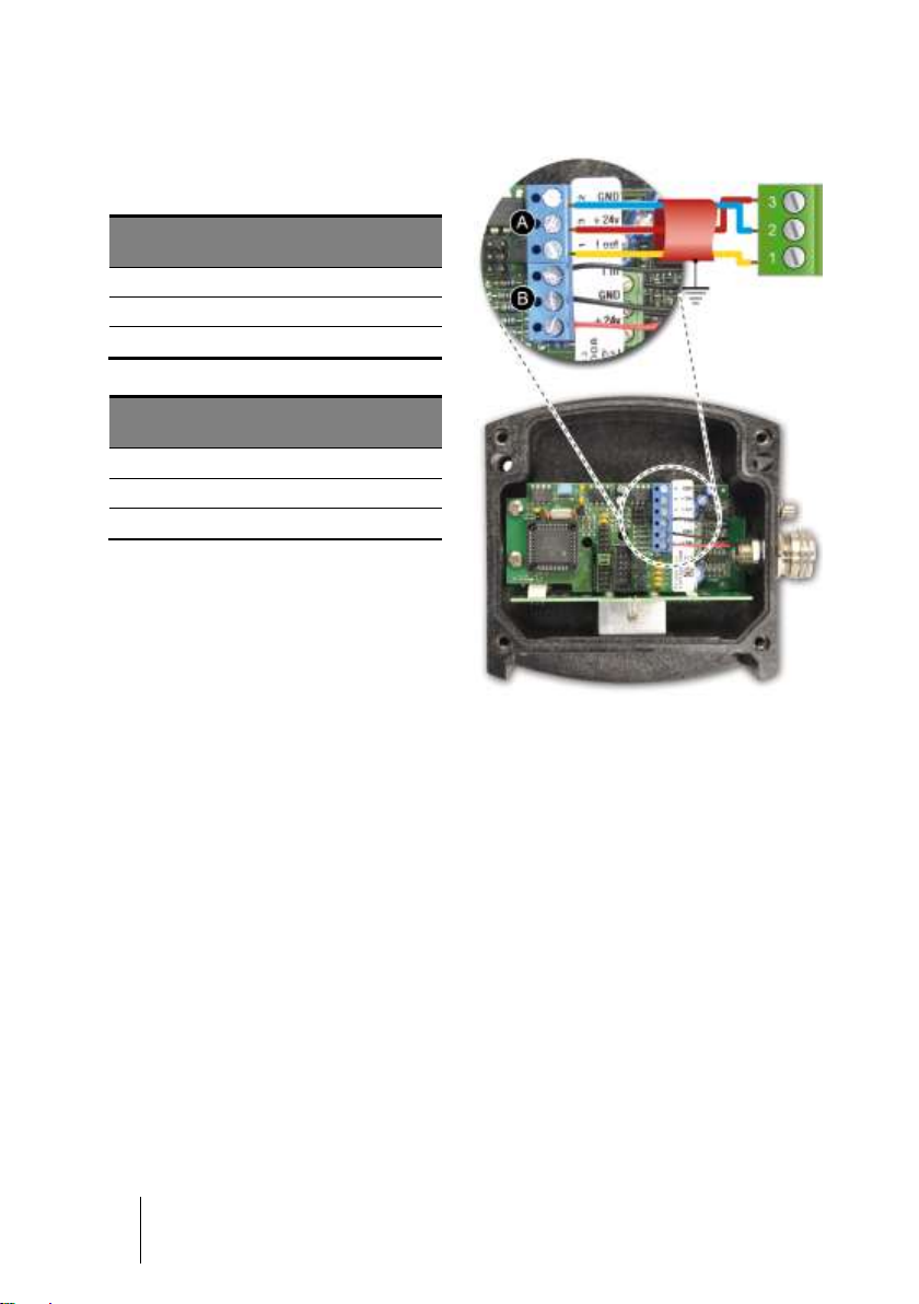
Connection of a 2-wire 4-20mA sensor to a non-Oldham control unit and to an
internal power supply
Figure 8: Connection of a 2-wire 4-20mA sensor to a non-Oldham control unit.
(A) Power supply 15< VCC<32V. I max = 30 mA.
Page 16
16
CTX 300
User manual
Operating mode
■ Remove the 4 screws (ref. 1).
■ Remove the cover (ref. 2).
Figure 9
■ Completely remove the screw (ref. 4).
■ Unscrew the screw a few turns
(ref. 3).
Figure 10
■ Turn the display circuit as shown
(ref. 5).
■ Connect the cable (ref. 6) to the
connector. Refer to paragraph
Connections for the various types of
sensors on page 13.
■ Return the display circuit to its original
position and replace the cover.
Figure 11
CTX300 with display
Page 17

3 - Installation and connection
17
■ Unscrew the 4 screws (ref. 1).
■ Remove the cover (rep. 2).
■ Proceed to wire the sensor according
to the terminal location.
Figure 12
CTX 300 without display
Page 18

18
CTX 300
User manual
Page 19

4 – Powering up
and use
19
■ The sensor turns on when connected
to a power supply.
■ If the sensor has a display, the green
LED will be lit (ref. 2) and a value will
appear on the display screen (ref. 1).
Figure 13
Figure 14: CTX 300 circuit board.
Figure 15: CTX 300 SC main circuit
board.
Chapter 4 | Powering up and use
Powering up
In case of a problem, verify that the maintenance switch (ref. 1), located on the main
circuit, is in the MES (measure) position.
Page 20

20
CTX 300
User manual
Figure 16: CTX 300 CO2 main circuit
board. This card does is not equipped
with a MES-CAL switch.
4-20 mA analog output
For CTX 300 sensors, except for the CO2 sensor, the 4-20 mA output current is
proportional to the gas level.
Notes:
■ The CO
■ MX 15 and MX 32 control units that integrate with the linearization of the CO
sensor are available upon request.
■ The MX 62 integrates with the linearization of CO
The various states of the 4-20 mA output are:
■ 1 mA to indicate a fault.
■ = 2 mA in Calibration position, except for the CO
calibration function.
■ Between 4 and 20 mA for measurement values.
■ ≥ 20 mA if levels exceed measurement range.
sensor can be equipped with a linearization board.
2
sensors.
2
sensor that does not have a
2
2
Page 21

5 – Maintenance
21
The adjustment operations in this paragraph are reserved for authorized,
trained personnel because they may compromise detection reliability.
Chapter 5 | Maintenance
Gas detectors are safety devices. OLDHAM recommends the regular testing of fixed
gas detection installations. This type of test consists of injecting the calibration gas into
the detector at a sufficient concentration to activate the pre-set alarms. It is to be
understood that this test is in no way a replacement for a detector calibration.
The frequency of gas tests depends on the industrial application where the detector is
in use. Frequent inspections should be made in the months following the
commissioning of the installation, and should then become more widely spaced
provided that no significant deviation is observed. If a detector should fail to react in
contact with the gas, calibration is essential. The frequency of calibrations shall be
appropriate according to the results of the tests (humidity, temperature, dust, etc.);
however, it must not exceed one year.
The general manager should put safety procedures in place on-site. OLDHAM cannot
be held responsible for their enforcement.
Calibration
Recommendations
Calibration consists of adjusting the zero of the clean air sensor and adjusting
sensitivity with a test gas. Adjustments are made at the sensor level.
Equipment needed to calibrate the detector correctly:
■ Flexible plastic tubing (Figure 17, ref. 2).
■ Manometer and regulator valve for the compressed gas cylinders (rep. 3).
■ 0 to 60 l/h flow meter (if the cylinder is not equipped with one).
■ Calibration pipe (ref. 1), which may vary depending on the nature of the gas (see
pages 37 and following).
■ Test gas cylinder (ref. 4).
Page 22

22
CTX 300
User manual
The detector should be calibrated using the intended flow-rate. The actual
concentration of gas may be underestimated if the detector was calibrated
with too high of a flow rate.
■ The sensor is operating: the green
light (ref. 1) is lit and the display
screen shows the measurement level.
Figure 18
Figure 17: sensor calibration assembly.
Zero adjustment should be performed in a gas and vapor free area. If this is not
possible, synthetic bottled air can be injected at a rate of 60 l/h.
Use a bottle of test gas to adjust sensor sensitivity (concentration close to the alarm
threshold or corresponding to 30% of the measurement range at a minimum). The
recommended rate is 60 l/h.
Note: when dealing with dangerous gases, you MUST consult a specialized Oldham
technician or use another sensor pack recently pre-calibrated at a factory.
CTX 300 calibration
1st case: CTX 300 with display (excluding O2)
Page 23

5 – Maintenance
23
■ Flip the maintenance switch (ref. 1)
into the CAL (calibration) position: the
yellow light (Figure 18, ref. 2) will be
lit and the sensor will send a 2 mA
current to the control unit
(Maintenance mode).
■ Verify that the sensor is located in a
clean-air environment. If not, inject
synthetic air at a flow rate of 30 l/h.
Figure 19
■ Wait for the measurement to stabilize
(displayed on screen) and adjust the
zero by using the ZERO
potentiometer located on the sensor
pack (ref. 2).
■ Inject the recommended calibration
gas at a flow rate of 30 l/h.
■ Wait for the measurement to stabilize.
■ Adjust the sensitivity by using the
sensitivity potentiometer located on
the sensor pack (rep. 1).
Figure 20
■ Stop injecting the calibration gas.
■ Remove the gas injection pipe, then
wait and verify that the signal returns
to zero. Repeat procedure if it does
not.
■ Flip the maintenance switch (rep. 1)
into the MES (measure) position. The
yellow light will turn off (Figure 18,
rep. 2).
■ Calibration is complete.
Figure 21
Page 24

24
CTX 300
User manual
2nd case: CTX 300 without display (except for O2, SC and C02)
■ The sensor is operating.
■ Flip the maintenance switch (ref. 1)
into the CAL (calibration) position: the
sensor will send a 2 mA current to the
control unit (Maintenance mode).
■ Verify that the sensor is located in a
clean-air environment. Use the
calibration kit and follow all
recommendations.
Figure 22
■ Connect a voltmeter to the AF+ and
AF- terminals (caliber mV/DC).
Figure 23
■ Wait for the signal to stabilize and
adjust the zero by using the ZERO
potentiometer located on the sensor
pack (Figure 24, ref. 2). The output
signal should be 0 mV.
■ Now inject the recommended test gas
at a flow rate of 30 l/h. Use the
calibration kit and follow all
recommendations.
■ Wait until the signal has stabilized.
Figure 24
■ Read the mV value on the voltmeter
(Figure 23), with the full scale at 1600
mV. Calculate the value to be read as
a function of your test gas.
Page 25

5 – Maintenance
25
■ Adjust the displayed value using the
potentiometer (Figure 24, rep.1).
Example
- CO sensor.
- Scale 0-300 ppm.
- Standard gas concentration: 100
ppm.
- Reading: 533 mV.
■ Shut off the calibration gas injection.
■ Withdraw the gas injection pipe.
■ Then wait and check that the scale
has returned to zero. Otherwise,
repeat the entire procedure.
■ Switch the maintenance on/off switch
to the MES (measure) position
(ref. 1).
Figure 25
Page 26

26
CTX 300
User manual
CTX 300 calibration for O2
■ See paragraph 1
st
case: CTX 300 with
display, on page 22. Proceed only
with adjusting sensitivity (rep. 1) by
injection of test gas.
Figure 26
■ See paragraph 2
nd
case: CTX 300
without display on page 24. Proceed
only with adjusting sensitivity (rep. 1)
by injection of test gas.
Signal value mV:
- 1600 mV for full scale, means 30 %
O2.
- 1115 mV for 20.9 % O2.
- 0 mV for 0% O2.
Figure 27
Note: the signal sent from the
CTX300 (toxic or oxygen) sensor to
the control unit can be measured on
the main circuit by connecting a
millivoltmeter to the pins designed for
this purpose (Figure 28).
- 400 mV corresponds to 4 mA.
- 2000 mV corresponds to 20 mA.
Figure 28
This sensor is an Oxygen type.
1st case: CTX 300 O2 with display
2nd case: CTX 300 O2 without display screen nor LED
Page 27

5 – Maintenance
27
■ Flip the switch (rep. 1) into the CAL
position.
Figure 29
■ Ensure that the sensor is in clean air,
otherwise inject synthetic air into it
using the calibration kit and referring
to the recommendations below.
Important: to correctly calibrate a
sensor equipped with a semiconductor cell, use of a humidifier kit
(code 6335919) is MANDATORY.
Using the humidifier kit
- Lift the lid (ref. A) and, using a
washbottle, moisten the filter,
without saturating it, with distilled
water
- Replace the lid and check that all
parts are properly assembled and
that the assembly is fully airtight.
- Adjust the flow rate to 60 l/h and
wait 10 minutes until the humidifier
is fully purged.
- Apply the gas introduction pipe
(ref. C) to the nose of the sensor
and wait at least five minutes for
the measurement to stabilize.
Note: the sensor must be powered
for at least two hours before any
adjustment can be made.
Figure 30: the humidifier kit.
(B) Filter
(A) Lid
(C) Gas input
pipe
(D) « Cristal » tubes.
Length: 0.5 m
To detector
To standard gas
cylinder
(gas input)
CTX 300 calibration (for Semiconductor)
This is a Semiconductor type sensor.
Page 28

28
CTX 300
User manual
■ Connect a voltmeter as indicated and
adjust, using potentiometer p5 (ref. 1).
The output signal must be equal to
880 mV.
■ Next, inject the calibration gas at a
flow rate of 30 l/h (refer to paragraph
Indications for calibrating the CTX
300 SC, on page 53).
■ Wait for the signal to stabilize and
adjust the signal with the sensitivity
potentiometer p6 (ref. 2).
The output signal should be:
Figure 31
U = 880 mV + 3520 mV x Cal gas concentration
Sensor measurement range
Example
Sensor measure
(% of full range)
Output signal
(mV)
0
880
50
2 640
100
4 400
■ Stop injecting the calibration gas.
■ Verify that the reading returns to zero
(880 mV). If it does not, repeat the
entire procedure.
■ Calibration is complete.
■ Flip the switch (ref. 1) into the MES
(Measure) position.
Figure 32
Page 29

5 – Maintenance
29
■ Warning: the sensor should be turned on for 15 minutes before
adjustments are made. The following text describes the steps
necessary to adjust the transmitter (first calibration).
■ Adjustment: if the current loop of the output signal has an impedance of
500 ohms, the power supply should never fall below 23 V DC.
■ Inject nitrogen at a rate of 30 l/h.
■ On the X1 terminal board, place an
ammeter between terminals 1 (+) and
2 (-).
■ With the potentiometer Z, adjust the
current to 4 mA.
■ With the ammeter still connected,
inject the test gas at a rate of 60 l/h.
■ Adjust the sensitivity with the
potentiometer S. Refer to the
paragraph Calibration curves, on
page 30 for sensors without
linearization cards.
■ If this fails, flip the J2 jumper and
begin again.
Figure 33
CTX 300 CO2 calibration
This is a Carbone dioxide type sensor.
Page 30
30
CTX 300
User manual
CTX 300 CO2 linearization card
■ If you use a linearization card, the
connection is the following.
Terminal A
Central terminal
number
2 (GND)
1
3 (+24V)
3
1 (I out)
2
Terminal B
Central terminal
number
In
Iout
GND
GND
+24V
+24V
Figure 34
Calibration curves
The following pages present the calibration curves, that means the output signal of
different CO2-IR transmitters.
■ CO
■ CO
■ CO
■ CO
sensor, 0-1 % scale.
2
sensor, 0-5 % scale.
2
sensor, 0-10 % scale.
2
sensor, 0-50 % scale.
2
Page 31

5 – Maintenance
31
ppm CO2
Display
% range
Current
mA
ppm CO2
Display
% range
Current
mA 0 0 4
5500
76
16.16
500
14
6.24 6000
79
16.64
1000
27
8.32 6500
82
17.12
1500
35
9.6 7000
85
17.6
2000
43
10.88 7500
88
18.08
2500
49
11.84 8000
90
18.4
3000
55
12.8 8500
93
18.88
3500
60
13.6 9000
96
19.36
4000
64
14.24 9500
98
19.68
4500
68
14.88
10000
100
20
5000
71
15.36
Figure 35: signal CO2-IR transmitter output signal – 0-1 % scale.
Page 32

32
CTX 300
User manual
% CO2
Display
% range
Current
mA
0,00 0 4,0
0,25
21.6
7.46
0,50
33.1
9.3
1,00
48.4
11.74
1,50
60.1
13.62
2,00
68.6
14.98
2,50
75.6
16.1
3,00
82.4
17.18
3,50
86.7
17.87
4,00
91.7
18.67
4,50
95.8
19.33
5,00
100
20
Figure 36: signal CO2-IR transmitter output signal – 0-5 % scale.
Page 33

5 – Maintenance
33
% CO2
Display
% range
Current
mA
0,00 0 4,0
1,00
41.25
10,6
2,00
56.875
13,1
3,00
67.5
14,8
4,00
75.625
16,1
5,00
80.625
16,9
6,00
86.875
17,9
7,00
91.25
18,6
8,00
95.625
19,3
9,00
98.75
19,8
10,00
100
20,0
0
2
4
6
8
10
12
14
16
18
20
0 1 2 3 4 5 6 7 8 9 10
Current mA
Concentration % CO
2
Figure 37 : signal CO2-IR transmitter output signal – 0-10 % scale.
Page 34

34
CTX 300
User manual
% CO2
Display
% range
Current
mA
% CO2
Display
% range
Current
mA 0 0
4,0 20
74.2
15.87
1
13.4
6.14 25
80.4
16.86
2
21.6
7.46 30
85.6
17.7
3
28.4
8.54 35
90.7
18.51
5
38.1
10.1 40
93.8
19.01
10
54.6
12.74 45
96.9
19.5
15
66
14.87 50
100
20
Figure 38 : signal CO2-IR transmitter output signal – 0-50 % scale.
Page 35

5 – Maintenance
35
For the preservation, protection and improvement of environmental
quality, and for the protection of human health and the prudent and
rational utilization of natural resources, the CTX 300 must be disposed of
separately from electronic equipment and cannot be disposed of with
normal household waste. The user therefore has an obligation to separate
the CTX 300 sensor from other waste to ensure that it is recycled safely
for the environment. For further details on existing collection sites, contact
the local administration or seller of the product.
Replacing a sensor
Sensors must be replaced:
■ When calibration is no longer possible (no sensitivity);
■ During preventative maintenance.
The replacement sensor should be identical to the original sensor (same gas, same
range). After a sensor has been replaced, a calibration or test (for pre-calibrated
sensors) must be conducted.
Disposal
Page 36

36
CTX 300
User manual
Page 37

6 – Spare parts
37
Replacement parts must imperatively be guaranteed origin Oldham.
Otherwise, material safety could be jeopardized.
P/N
Description
Picture
6147868
CTX 300 tool kit.
6322420
Mounting brace and bolts
(CTX 300) ceiling mount.
6323607
Gas collector (s).
6331137
Gas introduction device for O2, C0, H2S,
NO, H2.
6331141
Gas introduction device for explosible
gases and other toxic gases.
Chapter 6 | Spare parts
List of spare parts for different detectors.
CTX/COX 300 toxic or oxygen sensors
Page 38

38
CTX 300
User manual
P/N
Description
Picture
6327906
Device for remote gas introduction.
6335953
Replacement filter.
PTFE protector filter.
Pre-calibrated oxygen sensor pack
6313C2A
CTX 300 O2, 0-30 % vol sensor pack.
(2years)
6313C5A
CTX 300 O2, 0-30 % vol sensor pack.
(5years)
6313660
CTX 300 O2, 0-100 % vol sensor pack.
Pre-calibrated toxic sensor pack
6313627
CTX 300 CO - 100 ppm sensor pack.
6313628
CTX 300 CO - 300 ppm sensor pack.
6313629
CTX 300 CO - 1000 ppm sensor pack.
6313631
CTX 300 CO - 1% vol sensor pack.
6313632
CTX 300 CO - 10% vol sensor pack.
6313633
CTX 300 H2S - 30 ppm sensor pack.
6313634
CTX 300 H2S - 100 ppm sensor pack.
6313635
CTX 300 H2S - 1000 ppm sensor pack.
6313636
CTX 300 NO - 100 ppm sensor pack.
6313637
CTX 300 NO - 300 ppm sensor pack.
6313638
CTX 300 NO - 1000 ppm sensor pack.
6313639
CTX 300 NO2 - 10 ppm sensor pack.
6313640
CTX 300 NO2 - 30 ppm sensor pack.
6314001
CTX 300 NO2 - 100 ppm sensor pack.
6313645
CTX 300 ETO - 30 ppm sensor pack.
6313646
CTX 300 SO2 - 10 ppm sensor pack.
6313647
CTX 300 SO2 - 30 ppm sensor pack.
6313648
CTX 300 SO2 - 100 ppm sensor pack.
Page 39

6 – Spare parts
39
P/N
Description
Picture
6313649
CTX 300 Cl2 - 10 ppm sensor pack.
6313650
CTX 300 H2 - 30 ppm sensor pack.
6313651
CTX 300 H2 - 100 ppm sensor pack.
6313652
CTX 300 HCL - 30 ppm sensor pack.
6313653
CTX 300 HCL - 100 ppm sensor pack.
6313654
CTX 300 HCN - 10 ppm sensor pack.
6313655
CTX 300 HCN - 30 ppm sensor pack.
6313656
CTX 300 NH3 - 100 ppm sensor pack.
6313657
CTX 300 NH3 - 1000 ppm sensor pack.
6313893
CTX 300 NH3 - 0-5000 ppm sensor pack.
6313675
CTX 300 HF - 10 ppm sensor pack.
6313676
CTX 300 O3 - 1 ppm sensor pack.
6313677
CTX 300 PH3 - 1 ppm sensor pack.
6313919
CTX 300 PH3 - 1000 ppm sensor pack.
6313860
CTX 300 F2 - 1 ppm sensor pack.
6314183
CTX 300 CH2O - 50 ppm sensor pack.
6 314 185
CTX 300 ASH3 - 1 ppm sensor pack.
6313834
CTX 300 SIH4 - 50 ppm sensor pack.
6313678
CTX 300 ClO2 - 3 ppm sensor pack.
6313833
CTX 300 COCl2 - 3 ppm sensor pack.
Replacement parts
6323608
Cover without display.
6323609
Cover with display.
6815919
CTX 300 without display label.
6815921
CTX 300 wit display label.
6451466
Display card.
6815923
Localization sticker.
6451465
Motherboard.
Page 40

40
CTX 300
User manual
CSC 300 semiconductor sensors
P/N
Description
Picture
6147868
CTX 300 tool kit.
6322420
Mounting brace and bolts
(CTX 300 ceiling mount).
6323607
Gas collector (stainless).
6335919
Calibration kit (humidifier filter + pipe).
6335918
Humidifier filter.
Replacement sensors
6313544
Sensor for R134A, R11, R23, R143A,
R404A, R507, R410A, R32, R407C,
R408A.
6313545
Sensor for methyl chloride, methylene
chloride.
6313546
Sensor for solvents.
6313547
Sensor for R22, R12.
6313464
Sensor for VOC.
Replacement parts
6451396
Motherboard.
6143502
PG9 cable gland.
Page 41

6 – Spare parts
41
P/N
Description
Picture
6147868
CTX 300 tool kit.
6451618
Motherboard.
6351233
Linearization card.
6799188
Gas introduction device.
Replacement sensors
6451612
CO2 - 0 - 1 % sensor.
6451611
CO2 - 0-5 % or 0-10 % sensor.
6451610
CO2 - 0 - 50 % sensor.
Replacement parts
6815923
Localization sticker.
6851919
Self-adhesive front panel.
6143502
PG9 cable gland.
CTX 300 – CO2 sensors
Page 42

42
CTX 300
User manual
Page 43

7 - Certification
43
Chapter 7 | Certification
The following page reproduces the EC declaration of conformity.
Page 44

44
CTX 300
User manual
Document actualisé
Page 45

7 - Certification
45
Page 46

46
CTX 300
User manual
Page 47

8 – Technical specifications
47
Enclosure.
Polycarbonate housing.
Function.
Detector-transmitter
Display
Highly visible backlight display unit
(optional, gas dependent)
Indicator
lights
In operation: green color
(on CTX 300 : 3-wire)
Failure / maintenance: yellow color
Link
2 wires – CTX 300 without display unit
3 wires – CTX 300 with display unit
Cable entry
PG9 cable gland
(outer diameter 6 to 11 mm)
Power supply
15 to 32 V DC
Power
consumption
CTX 300 without display unit: 27 mA
CTX 300 with display unit: 110 mA
Infrared or semiconductor versions: 100mA
Operating
temperature
-40°C to + 50°C, 40°F to + 122°F sensor dependent
Sealing
IP 54, NEMA 3 & 3R
Weight
520 g
Dimensions
130 x 136 x 69 (l x h x d) in mm ; (5.12" x 5.35" x 2.72")
Certification
CCSA – Class 4812 10 – Signal Appliances-Detectors
CSAUS – Class 4812 86 - Signal Appliances-Miscellaneous
EMC
Type 1 according to EN 50270:06
Impedance
32 ohms max loop for CTX 300 with display unit and
for solid states and CO2 sensor versions
128 ohms max loop for CTX 300 without display unit
Chapter 8 Technical specifications
Page 48

48
CTX 300
User manual
Gas
Type of sensor
Range (ppm)
Operating
temperature
Relative
humidity
uncondensed
Accuracy (at
PA full scale)
Life span (in
month)
T(50)
(seconds)
O2
EC
30.0%
30.0%
100%
-20°C to +50°C
-40°C to +50°C
+5°C to +40°C
10% to 95% RH
10% à 95% RH
10% to 95% RH
+/-1.5%
+/-1.5%
+/-1.5%
28
60
36
10
10
<20
CO
EC
100
300
1000
1.00%
10.0%
-20°C to +50°C
-20°C to +50°C
-20°C to +50°C
-20°C to +50°C
-20°C to +50°C
10% to 95% RH
10% to 95% RH
10% to 95% RH
10% to 95% RH
10% to 95% RH
+/-1.5%
+/-1.5%
+/-1.5%
+/-1.5%
+/-1.5%
48
48
48
48
48
15
15
15
<20
<20
CO2
IR
1%
5%
10%
50%
-30°C to +45°C
-30°C to +45°C
-30°C to +45°C
-30°C, to +45°C
5% to 95% RH
5% to 95% RH
5% to 95% RH
5% to 95% RH
+/-2%
+/-2%
+/-2%
+/-2%
60
60
60
60
70(T90)
70(T90)
70(T90)
70(T90)
H2S
EC
30.0
100
1000
-20°C to +50°C
-20°C to +50°C
-20°C to +50°C
10% to 95% RH
10% to 95% RH
10% to 95% RH
+/-1.5%
+/-1.5%
+/-1.5%
36
36
36
15
15
15
NO
EC
100
300
1000
-20°C to +50°C
-20°C to +50°C
-20°C to +50°C
10% to 95% RH
10% to 95% RH
10% to 95% RH
+/-1.5%
+/-1.5%
+/-1.5%
36
36
36
15
15
15
NO2
EC
10.0
30.0
-20°C to +50°C
-20°C to +50°C
10% to 95% RH
10% to 95% RH
+/-1.5%
+/-1.5%
24
24
20
20
SO2
EC
10.0
30.0
100
-20°C to +50°C
-20°C to +50°C
-20°C to +50°C
10% to 95% RH
10% to 95% RH
10% to 95% RH
+/-1.5%
+/-1.5%
+/-1.5%
36
36
36
15
15
15
Cl2
EC
10.0
-20°C to +50°C
10% to 95% RH
+/-1.5%
24
50
H2
EC
2000
2.0%
-20°C to +50°C
-20°C to +50°C
10% to 95% RH
10% to 95% RH
+/-1.5%
+/-1.5%
24
24
50
50
HCl
EC
30.0
100
-20°C to +50°C
-20°C to +50°C
10% to 95% RH
10% to 95% RH
+/-1.5%
+/-1.5%
18
18
50
50
HCN
EC
10.0
30.0
-20°C to +50°C
-20°C to +50°C
10% to 95% RH
10% to 95% RH
+/-2%
+/-2%
24
24
30
30
NH3
EC
100
100
1000
5000
-20°C to +40°C
-40°C to +40°C
-20°C to +40°C
-20°C to +40°C
10% to 95% RH
10% to 95% RH
10% to 95% RH
10% to 95% RH
+/-3%
+/-3%
+/-3%
+/-3%
24
24
24
24
<20
<20
<20
<20
ETO
EC
30.0
-20°C to +50°C
10% to 95% RH
+/-3%
36
50
HF
EC
10.0
-10°C to +30°C
10% to 95% RH
+/-3%
12
50
O3
EC
1.00
-20°C to +50°C
10% to 95% RH
+/-3%
18
40
Page 49

8 – Technical specifications
49
Gas
Type of sensor
Range (ppm)
Operating
temperature
Relative
humidity
uncondensed
Accuracy (at
PA full scale)
Life span (in
month)
T(50)
(seconds)
PH3
EC
1.00
-20°C to +50°C
10% to 95% RH
+/-3%
12
40
ASH3
EC
1.00
-20°C to +50°C
10% to 95% RH
+/-3%
12
40
ClO2
EC
3.00
-20°C to +50°C
10% to 95% RH
+/-2%
24
50
COCl2
EC
3.00
-20°C to +40°C
10% to 95% RH
+/-1.5%
18
50
Methylene
chloride
SC
500
-20°C to +55°C
10% to 95% RH
+/-15%
relative to
alarm
threshold
36
40
Methyl chloride
SC
500
-20°C to +60°C
10% to 95% RH
36
40
Toluene
SC
500
2000
-20°C to +50°C
-20°C to +50°C
10% to 95% RH
10% to 95% RH
36
36
20
20
Trichloroethylene
SC
500
-20°C to +60°C
10% to 95% RH
36
40
Xylene
SC
500
2000
-20°C to +50°C
-20°C to +50°C
10% to 95% RH
10% to 95% RH
36
36
20
20
Ethanol
SC
500
5000
-20°C to +50°C
-20°C to +60°C
10% to 95% RH
10% to 95% RH
36
36
20
20
R12
SC
10000
-20°C to +55°C
10% to 95% RH
36
30
R22
SC
2000
-20°C to +55°C
10% to 95% RH
36
30
R123
SC
2000
-20°C to +55°C
10% to 95% RH
36
30
R134a
SC
2000
-20°C to +55°C
10% to 95% RH
36
30
R11
SC
10000
-20°C to +55°C
10% to 95% RH
36
30
R23
SC
10000
-20°C to +55°C
10% to 95% RH
36
30
R143a
SC
2000
-20°C to +55°C
10% to 95% RH
36
30
R404a
SC
2000
-20°C to +55°C
10% to 95% RH
36
30
R507
SC
2000
-20°C to +55°C
10% to 95% RH
36
30
R410a
SC
1000
-20°C to +55°C
10% to 95% RH
36
20
R32
SC
1000
-20°C to +55°C
10% to 95% RH
36
20
EC : Electrochemical
IR : Infrared
SC : Semiconductor
Page 50

50
CTX 300
User manual
Page 51

9 – Annex
51
Chapter 9 | Annex
Wiring specification
Subject
This specification defines the general principles that apply to the design and
manufacture of grounding devices for Oldham instrumentation.
Reference documents
The electrical installation shall comply with French regulations in force, with all
European directives, all AFNOR standards and codes in force, insofar as they apply,
as well as the client’s general and particular specifications.
■ NFC 15-100 : Requirements for Low Voltage electrical installations.
■ NFC 17-100 : Protection against lightning – Installation of lightning rods.
■ EMC : Electromagnetic compatibility - Directive 89/336/EEC.
Applicable regulations
■ Decree No. 88-10546 of 11/14/88 (worker protection).
■ Edict of 12/19/88 (conditions for equipment installation in places presenting a risk of
explosion).
■ Decree No. 78-779 of 07/17/78 modified by Decree No. 81-440 of 05/05/81
amended on 07/01/91.
■ Edict of 04/06/81 and 09/07/82.
■ Edict of 03/31/80 (regulations for electrical installations in facilities regulated as part
of the legislation on classed installations likely to present a potential risk of
explosion).
General design
See all attachments, as well as the particular specifications below.
Page 52

52
CTX 300
User manual
Raceways
Metal raceways are grounded using “Force” metal masses; cross-sectional area of the
grounded network is 10 mm2.
Junction boxes
If polyester junction boxes are used, they must be equipped with:
■ A tapped metal plate so as to interconnect the mass of the metal cable glands.
■ An external ground connection of 4 mm
2
.
The connection to the metal masses grounding network is made with a bare galvanized
steel conductor.
The loop resistance for the control unit /sensor cable connection will vary according to
the type of sensor and type of control unit being used.
Refer to the technical manuals appropriate for your use.
Acceptable cable types
Acceptable cable types subject to adherence to the recommendations of this
specification.
Examples (yellow/green not included), non-exhaustive list.
■ Non-ATEX zone: CNOMO FRN05 VC4V5-F.
■ Non-ATEX zone: LYCY.
The cables listed below were not included in the electromagnetic compatibility tests for
our products. Use at your own risk.
■ U1000 R2V(FV).
■ U1000 RGPFV-RH.
■ A/H07 RN-F.
■ FRN07 RN-F.
■ GVS-RH.
Page 53

9 – Annex
53
P/N
Gas types
Measurement
range
After sale service
standard gas
Test gas
6313545
Methane
CH4
100% LEL
20 % LEL
1 % CH4
Hydrogen
H2
100% LEL
20 % LEL
0.8 % H2
Butane
C4H10
100% LEL
20 % LIE LEL 0.37
% C4H10
Propane
C3H8
100% LEL
20 % LEL
0.4 % C3H8
Methyl Chloride
CH3Cl
500 ppm
50 ppm CH3Cl
2000 ppm H2 = 190
ppm ± 25ppm
Methylene chloride
CH2Cl2
500 ppm
100 ppm CH2CL2
100 ppm CO = 80ppm
± 15 ppm
6313546
Trichloroethylene
C2HCl3
500 ppm
75 ppm
Trichloroethylene
300 ppm CO = 120
ppm ± 35ppm
Toluene
C6H5CH3
2 000 ppm
100 ppm Toluene
300 ppm CO =
330ppm ± 50ppm
Xylene
C6H4 (CH3)2
2 000 ppm
100 ppm Xylene
300 ppm CO =
330ppm ± 50ppm
Ethanol
C2H5OH
5 000 ppm
1000 ppm Ethanol
1000ppm H2 = 880ppm
± 150ppm
6313547
Freon R12
1 % volume
1000 ppm R12
0.5%CH4=overscale
Freon R22
2000 ppm
1000 ppm R22
0.5% CH4 = 750ppm ±
200ppm
6313544
Freon R134A
2000 ppm
1000 ppm R134A
0.5% CH4 = 2000ppm
± 500ppm
Freon R11
1% volume
1000 ppm R134A =
150 ppm
0.5% CH4=overscale
Freon R23
1% volume
1000 ppm R22 =
4500ppm
0.5% CH4 = 2800ppm
±800ppm
Indications for calibrating the CTX 300 SC
This information relates to the CTX 300 semiconductor.
Page 54
54
CTX 300
User manual
CTX 300 overview
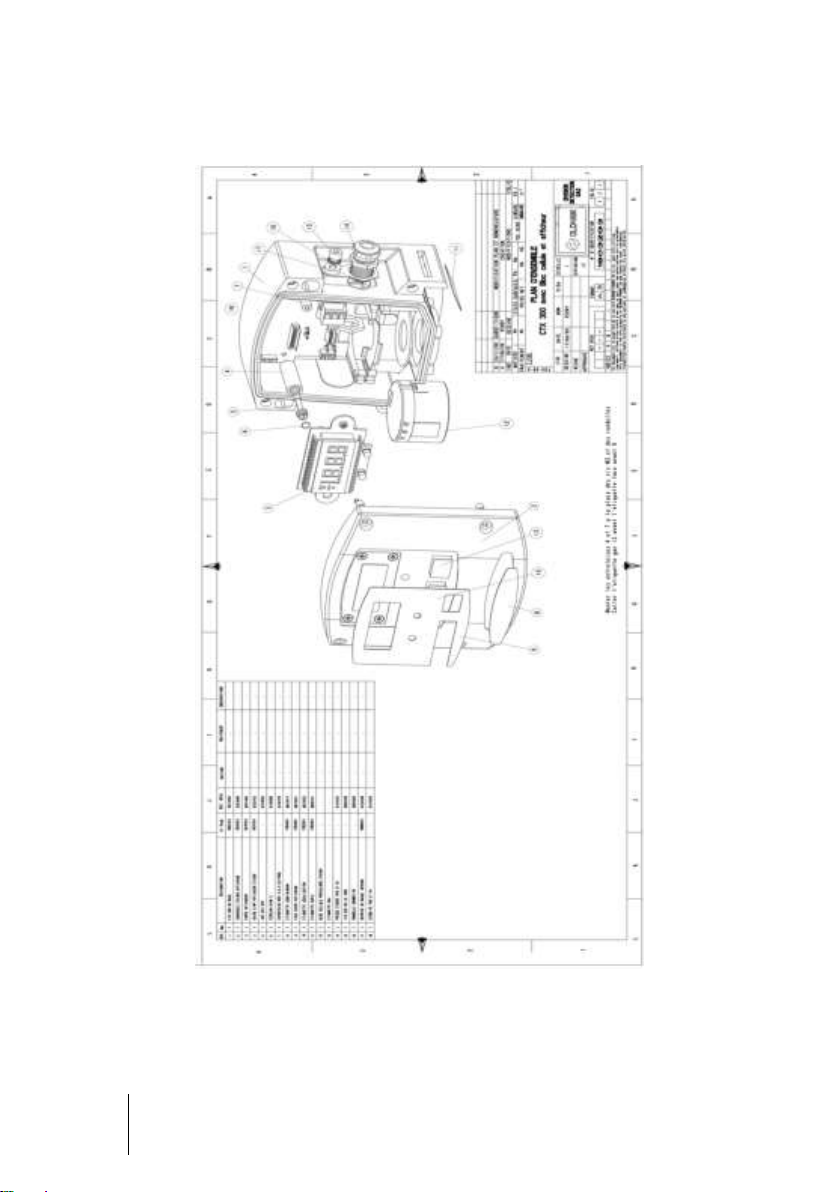
Figure 39: CTX 300 with sensor pack and display – overview.
Page 55

9 – Annex
55
Figure 40: CTX 300 – overview.
Page 56

56
CTX 300
User manual
Figure 41: CTX 300 semiconductor– overview.
Page 57

9 – Annex
57
Figure 42: CTX 300 infrared – 1% volume CO2 – overview.
Page 58

58
CTX 300
User manual
Figure 43: CTX 300 infrared – 5% volume CO2 – overview.
Page 59

9 – Annex
59
Figure 44: CTX 300 infrared – 10% volume CO2 – overview.
Page 60

60
CTX 300
User manual
Figure 45: CTX 300 infrared – 50% volume CO2 – overview.
Page 61

61
Page 62

Page 63

63
Page 64

The Fixed Gas Detection Experts
EUROPEAN PLANT AND OFFICES
Z.I. Est – rue Orfila CS 20417 – 62027 Arras Cedex FRANCE
Tél: +33 (0)3 21 60 80 80 – Fax: +33 (0)3 21 60 80 00
Website: http://www.oldhamgas.com
AMERICAS
Tel: +1 713-559-9280
Fax: +1 281-292-2860
americas@oldhamgas.com
ASIA PACIFIC
Tel: +86-21-3127-6373
Fax: +86-21-3127-6365
sales@oldhamgas.com
EUROPE
Tel: +33-321-608-080
Fax: +33-321-608-000
info@oldhamgas.com
 Loading...