

Page 1
BM 25/25W
Area
Gas Monitor
Part Number: NPB25EN
Version: L.2
User Manual
Page 2

2
BM 25/25W
Instruction Manual
Copyright Mars 2016 by Oldham S.A.S.
All rights reserved. The reproduction of all or any section of this document in
any form whatsoever without the written permission of Oldham S.A.S. is
forbidden.
The information contained in this manual is accurate to our knowledge.
As a result of continuous research and development, the specifications of
this product may be modified at any time without prior notice.
Oldham S.A.S.
Rue Orfila
Z.I. Est – CS 20417
62027 ARRAS Cedex
Tel.: +33 (0)3 21 60 80 80
Fax: +33 (0)3 21 60 80 00
Page 3

Table of Contents
3
Contents
Chapter 1 | Introduction ........................................................... 9
General information .................................................................................... 9
Product Overview ..................................................................................... 10
Additional equipment ................................................................................ 12
Connections ............................................................................................. 13
Gas sensors ............................................................................................. 15
LCD Display ............................................................................................. 16
Visual alarm.............................................................................................. 17
Audible alarm ........................................................................................... 17
Sampling system ...................................................................................... 17
Chapter 2 | Installation and Connections .............................. 19
Power supply ............................................................................................ 19
Charging the batteries .............................................................................. 19
Alarm Transfer.......................................................................................... 21
Connection of a manual call point ............................................................ 22
Chapter 3 | Operation ............................................................. 23
Start-up ..................................................................................................... 23
Gas monitor positioning ........................................................................... 24
Diffusion mode ......................................................................................... 24
Aspirated mode (with pump option) ......................................................... 25
Measurements.......................................................................................... 27
Alarms ...................................................................................................... 29
Data transfer............................................................................................. 32
Switching off the instrument ..................................................................... 33
Chapter 4 | Wireless Version ................................................. 35
Overview .................................................................................................. 35
Start-up ..................................................................................................... 39
Self-healing .............................................................................................. 42
Mac list menu ........................................................................................... 45
Chapter 5 | Maintenance ........................................................ 47
Accessing maintenance menus ............................................................... 47
Program Menu.......................................................................................... 48
Page 4

4
BM 25/25W
Instruction Manual
Sensor calibration menu .......................................................................... 50
Auto-adjustment menu ............................................................................. 50
Date and time management menu ........................................................... 50
Radio communication menu ..................................................................... 50
MAC List menu ......................................................................................... 50
Exit menu ................................................................................................. 50
Chapter 6 | COM2100 software .............................................. 51
Subject ..................................................................................................... 51
Gas monitor connection ........................................................................... 52
Maintenance menu ................................................................................... 52
Alarm relay configuration and logic inputs ............................................... 57
Screen menu ............................................................................................ 58
Chapter 7 | Technical Specifications ..................................... 59
Gas monitor .............................................................................................. 59
Sensors .................................................................................................... 61
Chapter 8 | Accessories and Spare Parts ............................. 67
Accessories .............................................................................................. 67
Spare Parts .............................................................................................. 68
Chapter 9 | Special Instructions for use in explosive
atmospheres or hazardous locations ...................................... 71
ATEX areas and general rules ................................................................. 72
Input/output parameters ........................................................................... 72
Trickle charging connection (external power source) .............................. 73
Connectors wiring diagram ...................................................................... 73
ATEX and IECEx Markings ...................................................................... 74
Radio Communication Marking ................................................................ 75
Chapter 10 | Declaration of EC Conformity .......................... 77
Page 5

General Information
5
Thank you for choosing this OLDHAM instrument.
All of the necessary actions have been taken in order to ensure your complete
satisfaction with this equipment.
It is important that you read this entire manual carefully and thoroughly.
The extent of our responsibility
■ OLDHAM shall not be held responsible for any damage to the equipment or for any
physical injury or death resulting in whole or in part from the inappropriate use,
installation, or storage of the equipment, which is the result of not complying with
the instructions and warnings, and/or with the standards and regulations in force.
■ OLDHAM does not support or authorize any business, person, or legal entity in
assuming responsibility on behalf of OLDHAM, even though they may be involved
in the sale of OLDHAM products.
■ OLDHAM shall not be responsible for any damage, direct or indirect, or for
damages and interest, direct or indirect, resulting from the sale and use of any of its
products UNLESS SUCH PRODUCTS HAVE BEEN DEFINED AND CHOSEN BY
OLDHAM FOR THE USE THAT THEY ARE INTENDED.
Ownership clauses
■ Drawings, specifications, and information herein contain confidential information
that is the property of OLDHAM.
■ This information shall not, either in whole or in part, by physical, electronic, or any
other means whatsoever, be reproduced, copied, divulged, translated, or used as
the basis for the manufacture or sale of OLDHAM equipment, or for any other
reason without the prior consent of OLDHAM.
Page 6

6
BM 25/25W
Instruction Manual
IMPORTANT: Read and understand this manual before operating.
WARNING: SERVICING THE UNIT OR CHANGING THE BATTERIES
MUST ONLY BE DONE IN AN AREA KNOWN TO BE NONHAZARDOUS.
Prior to each day’s use, a bump test should be performed. If the instrument
does not pass the bump test, a full calibration is recommended.
Oxygen deficient atmospheres may cause combustible gas readings to be
lower than actual concentrations.
Oxygen enriched atmospheres may cause combustible gas readings to be
higher than actual concentrations.
Verify the calibration of the combustible gas sensor after any incident where
the combustible gas content has caused the instrument to display an overrange condition.
Silicone compound vapors or other known contaminants may affect the
combustible gas sensor and cause readings of combustible gas to be lower
than actual gas concentrations. If the instrument has been used in an area
where silicone vapors were present, always calibrate the instrument before
next use to ensure accurate measurements.
Sensor openings and water barriers must be kept clean. Obstruction of the
sensor openings and/or contamination of the water barriers may cause
readings to be lower than actual gas concentrations.
When in the hazardous area, connections to the battery charging or
communications ports must be done in accordance with this technical
manual.
WARNING: Substitution of components may impair intrinsic safety and may
cause an unsafe condition.
Warnings and cautionary statements
This is not a contractual document. In the best interest of its customers and with the
aim of improving performance, OLDHAM reserves the right to alter the technical
features of its equipment without prior notice.
IMPORTANT: Failure to perform certain procedures or note certain conditions may
impair the performance of this product. For maximum safety and optimal performance,
please read and follow the procedures and conditions listed below.
Page 7

General Information
7
CAUTION: For safety reasons, this equipment must be operated and
serviced by qualified personnel only. Read and understand the instruction
manual completely before operating or servicing.
CAUTION: High off-scale readings may indicate explosive concentration.
CAUTION: Any rapid up-scale reading followed by a declining or erratic
reading may indicate a gas concentration beyond the upper scale limit which
may be hazardous.
CAUTION: Before each day’s usage, sensitivity must be tested on a known
concentration of pentane or methane equivalent to 25%-50% of full scale
concentration. Accuracy must be within -0% to +20% of actual
concentration. Accuracy may be corrected by referring to the zero/calibration
section of the instruction manual.
BM 25/25W (with radio communication module) complies with Part 15 of
FCC Rules. Operation is subject to the following two conditions: (1) This
device may not cause harmful interferences, and (2) this device must accept
any interference received, including interference that may cause undesired
operation.
BM 25/25W complies with FCC Maximum Permissible Exposure (MPE)
requirements when used with an approved antenna and the antenna is at
least 20cm away from the user. Use of the product closer than 20cm may
exceed the MPE limits. Use of any antenna other than approved antennas
will invalidate the certification of the product.
European Union (and EEA) only. This symbol indicates that, in conformity
with directive DEEE (2002/96/CE) and according to local regulations, this
product may not be discarded together with household waste.
Warranty
■ Under normal conditions of use and on return to the factory, parts and workmanship
carry a two year warranty, excluding consumables such as sensors, filters, etc.
Destruction of the equipment
It must be disposed of in a collection area that is set aside for this purpose, for example
at a site that is officially designated for the recycling of electrical and electronic
equipment (EEE) or a point of exchange for authorized products in the event of the
acquisition of a new product of the same type as before.
Page 8

8
BM 25/25W
Instruction Manual
Page 9
1 – Introduction
9
Chapter 1 | Introduction
General information
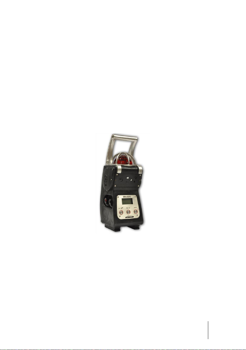
The BM 25/25W is a portable gas monitor that can be used in explosive gas
atmospheres.
It provides simultaneous detection of up to five gases present in the air by means of
sensors specific to each risk to be evaluated (under-oxygenation, presence of
combustible or toxic gases).
Figure 1
Page 10
10
BM 25/25W
Instruction Manual
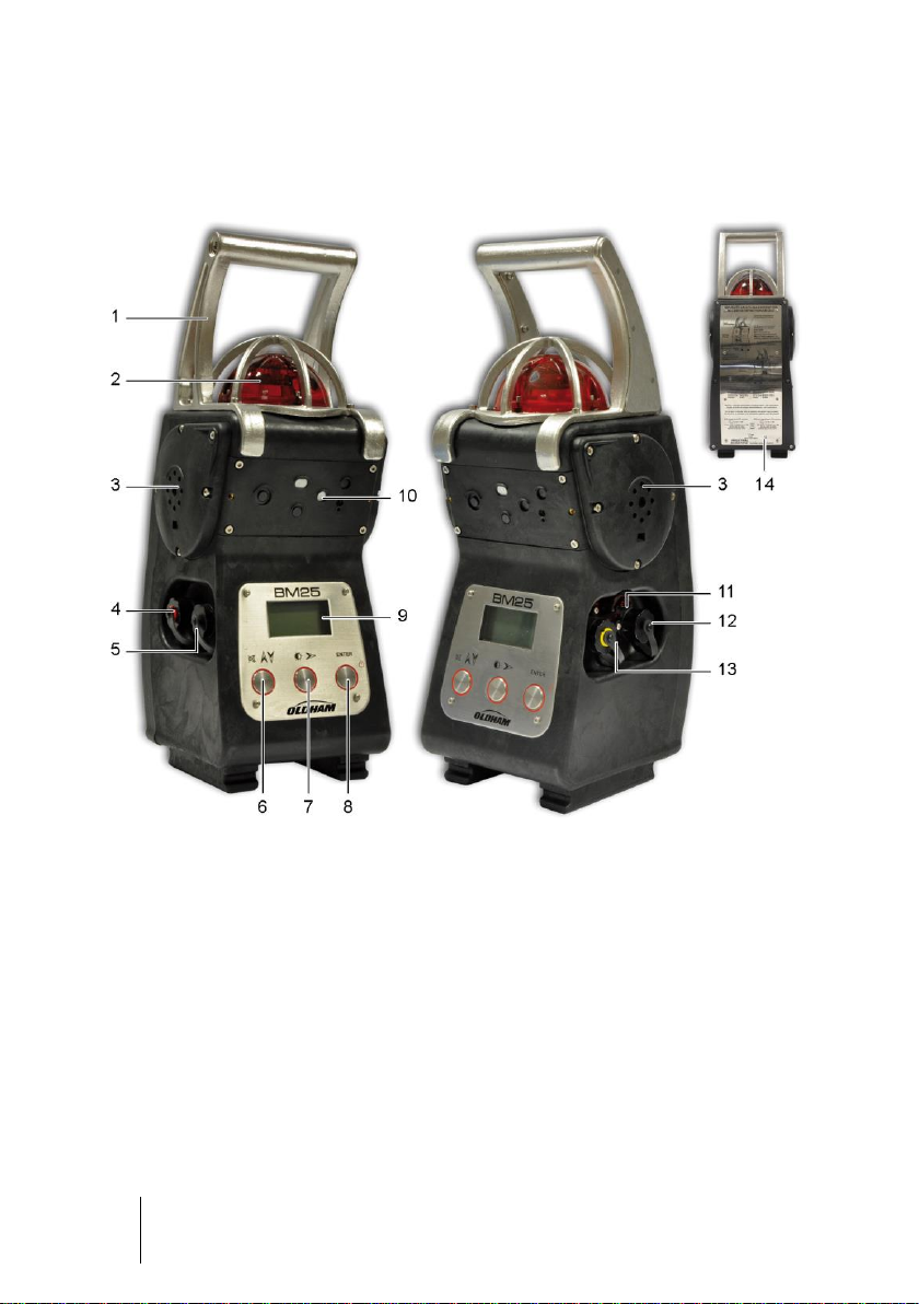
Product Overview
Figure 2: Product Overview
Page 11

1 – Introduction
11
Ref.
Description
See page
1.
Carrying handle
2.
LED alarm indicator (visual warning for gas alarms, transferred
alarms and faults)
■ Low Alarm: slow flash (1 Hz)
■ High Alarm: rapid flash (2 Hz)
■ Alarm Transfer: very slow flash (0.5 Hz)
■ Fault: steady (0 Hz)
29
3.
Loud speakers (audible warning for gas alarms, transferred
alarms and faults)
■ Low Alarm: two-tone, slow (1 Hz)
■ High Alarm: two-tone, rapid (2 Hz)
■ Alarm Transfer: two-tone, very slow (0.5 Hz)
■ Fault: mono-tone, continuous (0 Hz)
29
4.
Charging port connection (red ring)
19
5.
Trickle charge port connection (black ring)
20
6.
Alarm acknowledgement and Menu key (*)
-
7.
Backlight/Menu key (*)
-
8.
On/Off/Enter key (*)
23
9.
LCD display
16
10.
Gas sensors
15
11.
Infrared port connection
51
12.
Relay outputs (black ring)
14
13.
Dry logic inputs (yellow ring)
14
14.
Brief instructions for use and approval label
-
(*) Push buttons are "piezo" type
Page 12
12
BM 25/25W
Instruction Manual
Ref.
Description
See page
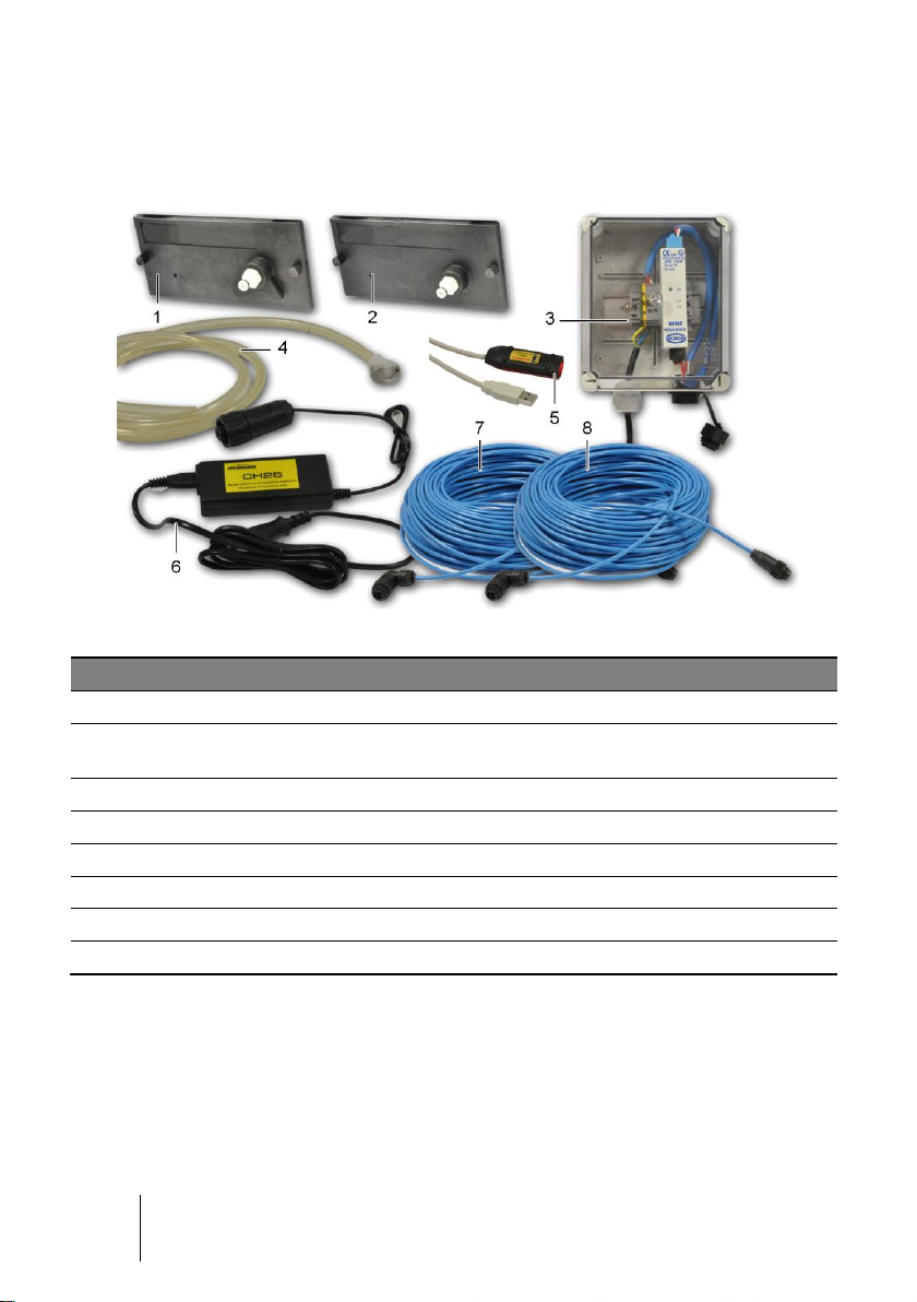
1.
Sensors Cover for use with aspirated versions (*)
25
2.
Calibration cup for use with manual sampling system or for
sensors calibration
26
3.
Intrinsically Safe Trickle Charge Kit (provided with cables)
20
4.
Calibration/Sample tubing
-
5.
Communication Adaptor
51
6.
Universal charger 110/230 VAC
19
7.
Cable for IS power supply (see 3)
-
8.
Cable for alarm transfer (25, 50 or 100 meters)
21
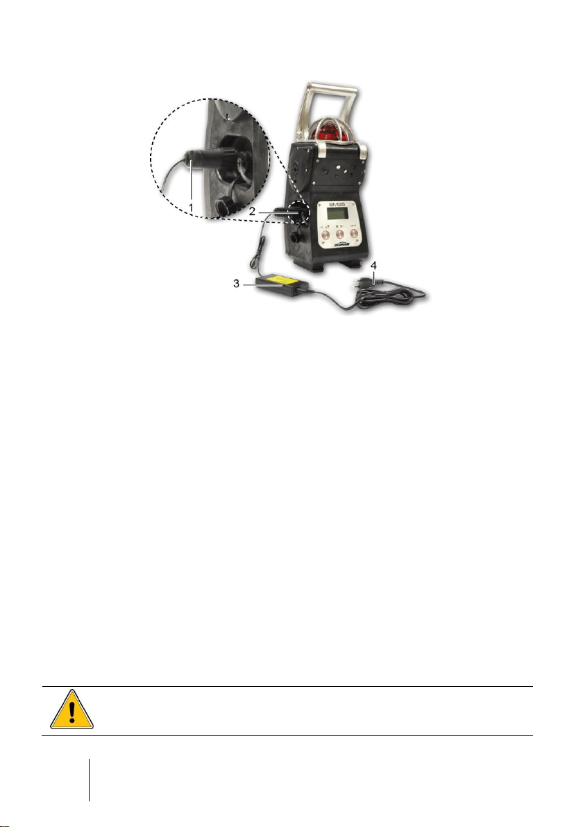
Additional equipment
Figure 3: accessories
(*) Optional
Page 13
1 – Introduction
13
■ Connection to Oldham universal charger
(110/230 VAC) or charger for vehicle (12/30
VDC)
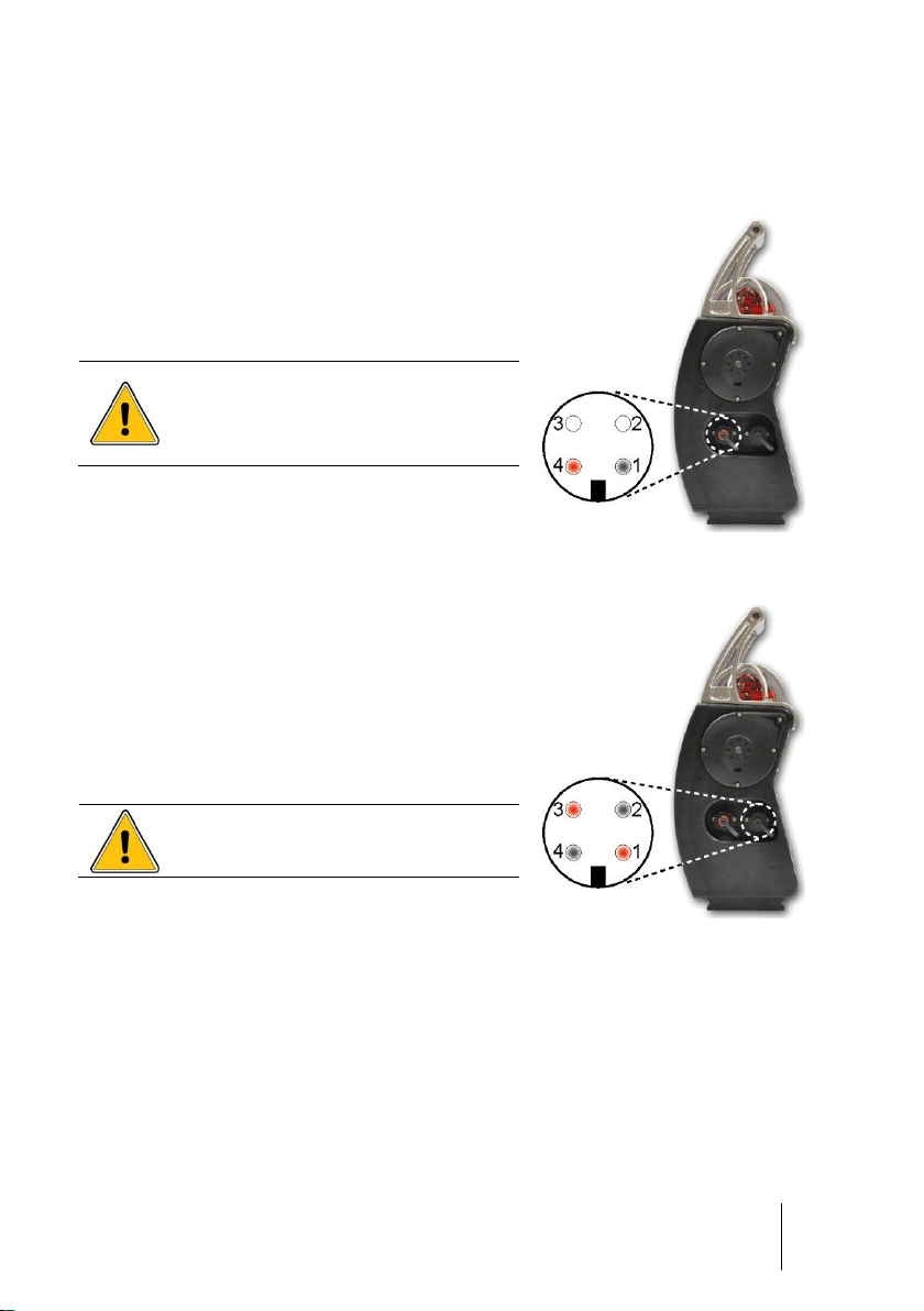
■ Pin 1: V- charge
■ Pin 4: V+ charge
Connection prohibited in hazardous
area.
Unused connectors must be
equipped with their protective cap.
See details on pages 19.
Figure 4: local charging port
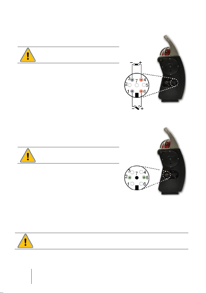
■ Only for connection to the intrinsically safe
certified trickle charger
■ Pin 1: V+ trickle charge
■ Pin 2: V- trickle charge
■ Pin 3: V+ trickle charge
■ Pin 4: V- trickle charge
Pins 1-3 and 2-4 are connected in parallel.
Unused connectors must be
equipped with their protective cap.
See details on page Erreur ! Signet non défini..
Figure 5: trickle charge port
Connections
Charging port connection (red ring)
Trickle charge port connection (black ring)
Page 14
14
BM 25/25W
Instruction Manual
■ Pins 1-6: alarm relay (NO) output
■ Pins 3-4: fault relay (NC) output
Unused connectors must be equipped
with their protective cap.
See details on pages 21 and 57.
Figure 6: relay outputs
■ Pin 2: logic input for alarm transfer
■ Pin 5: logic input for alarm acknowledgement
■ Pin 7: common ground
Unused connectors must be equipped
with their protective cap.
See details on pages 22 and 57.
Intrinsic safety parameters
■ Alarm relay output: dry relay contact,
Ui = 30 V, Ii = 150 mA, no L or C
condition
■ Power supply for trickle charging: Ui = 30 V,
Ii = 160 mA, no L or C condition
■ Dry logic input: Uo = 5 V, Io = 50 mA, Lo = 8
mH, Co = 7 µF
Figure 7: dry logic inputs
The person responsible for the gas monitor must create a Descriptive
System Document (for intrinsically safe circuits).
Relay Outputs (black ring)
Dry logic inputs (yellow ring)
Page 15
1 – Introduction
15
Ref.
Description
1.
Combustible gas sensor (0 to 100% LEL)
2.
Mini sensors for toxic gases or the 1 year O2 sensor
3.
Mini sensors for toxic gases or the 1 year O2 sensor
4.
Medium sensors for:
■ O
2
(>2 year lifetime)
■ CO/H
2
S (combo medium sensor) and other toxic gases
■ CO
2
IR
5.
Medium sensors for:
■ O
2
sensor (>2 year lifetime)
■ Toxic gases (medium sensors except CO/H
2
S sensor)
■ CO
2
IR
■ Infrared sensor for combustible gases
■ PID sensor for VOCs (Volatile Organic Compounds)
Gas sensors
The sensors are located on the front of the monitor (Figure 2, ref. 10). They are smart,
pre-calibrated from factory and interchangeable. They are composed of a sensitive
element and electrical components, including an EEPROM memory in which the
sensor characteristics are stored (gas type, range, span value, instantaneous, STEL
and TWA alarm values, date of manufacture, serial number, date of last calibration,
span reserve, etc.). The span reserve is updated after each calibration and allows the
user to gage the optimal time for changing the sensor. Sensors must be positioned as
indicated in the table above.
Figure 8: sensors configuration
Page 16
16
BM 25/25W
Instruction Manual
Sensor slots and protection filters must be kept clean. Otherwise, gas
measurements could be jeopardized.
Note:
■ If a sensor is present in slot #5, then sensor in slot #2 is not monitored
■ The “combo” CO/H
■ The PID sensor can only be plugged in slot #5
S sensor can only be plugged in slot #4
2
LCD Display
The instrument features a graphic LCD display with backlit (Figure 2, ref. 9). It
automatically illuminates when an alarm or a fault occurs. It can be rotated by 180°
using COM2100.
Figure 9: LCD display
The following information is displayed:
■ Up to 5 gas measurements along with gas names and units
■ Maintenance call for calibration
■ Date and time
■ Minimum and maximum values (peak) measured
■ STEL (short-term exposure limit) and TWA (time-weighted average) values
■ Remaining battery runtime (bargraph)
■ User’s and/or location’s identification
■ Maintenance menus
■ Alarm events (gas alarm, alarm transfer, sensor fault, battery fault, etc.)
Page 17

1 – Introduction
17
Visual alarm
A red bright flashlight (Figure 2, ref. 2) visible from all direction is located on the top of
the device and alerts the user in the event of an alarm.
Audible alarm
Two powerful speakers (103 dB at 1 meter) located on each side of the BM 25/25W
(Figure 2, ref. 3) alert the user in the event of an alarm.
Sampling system
The gas monitor can be equipped with an internal electric pump or an external manual
aspirator for confined space monitoring.
Page 18

18
BM 25/25W
Instruction Manual
Page 19
2 – Installation and Connections
19
The gas monitor is approved for use in explosive atmosphere only when it
is equipped with the battery pack type recommended by the manufacturer.
Before changing the battery pack, make sure the instrument is off.
Charging the BM 25/25W with the truck-charger or the universal charger
shall be done in non-classified area only.
Chapter 2 | Installation and
Connections
Power supply
General Information
Power is supplied to the gas monitor through an interchangeable and rechargeable
battery pack (NiMH 7.2 V / 9 Ah). Under normal usage conditions and no radio
communication, the battery life ranges from 40 to 170 hours depending on the
configuration (100 hours under typical configuration: diffusion mode with 1 catalytic or 1
infrared sensor and 2 electrochemical sensors). For the wireless version, the battery
life ranges from 35 to 135 hours (65 hours under standard configuration).
Charging the batteries
Charger for vehicle (12 to 30 VDC) or 110/230 VAC universal charger
Insert the male connector (Figure 10, ref. 1) from the charger (ref. 3) into the
corresponding charging port and identified with a red ring (ref. 2) on the BM 25/25W.
Connect the other end of the power supply (ref. 4) to the power source. Charging time
is 4.5 hours with the 110/230 VAC universal charger.
Page 20
20
BM 25/25W
Instruction Manual
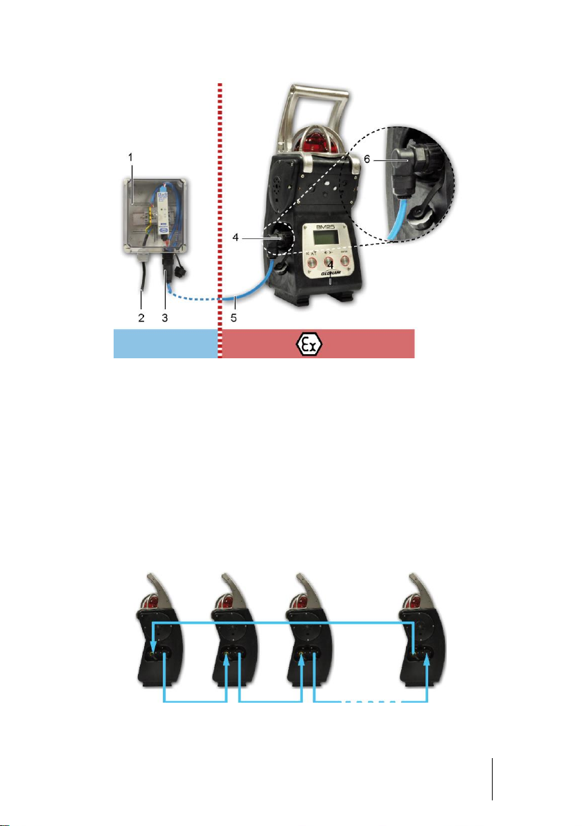
The trickle charge connector (Figure 11, ref. 1) must be located in a nonhazardous location. The BM 25/25W can be used in hazardous area while
trickle charging.
Figure 10: charging in safe area
Trickle charge kit
An intrinsically safe power supply (Figure 11: trickle charger connection provides power
to the monitor while it is located in hazardous area through a dedicated connector on
the left side (Figure 2, ref. 5). In this configuration, the internal battery is charged very
slowly. The current supplied by the trickle charger is mostly used to power the electrical
circuits.
Intrinsically safe power supply (trickle charger) features:
■ Io ≤ 160 mA.
■ Pmax= 1.2 W.
■ Maximum cable resistance = 16 ohm, based on a maximum cable length of 500
meters (AWG 16 – 1,5mm²).
Trickle chargers are available with 25, 50 or 100 meters of cable. The dual charging
kits are intended for use with BM 25/25W monitors equipped with two high current
draw sensors (catalytic, infrared, PID) or when the pump is continuously running. Only
intrinsically safe power supplies provided by OLDHAM can be used.
Insert the male connector (Figure 11, ref. 6) from the trickle charger (ref. 1 and 3) into
the port with a black ring that is located on the left side of the BM 25/25W (ref. 4).
Connect the other end of the power supply (ref. 2) to the mains and only in areas
known to be safe.
Page 21
2 – Installation and Connections
21
Figure 11: trickle charger connection
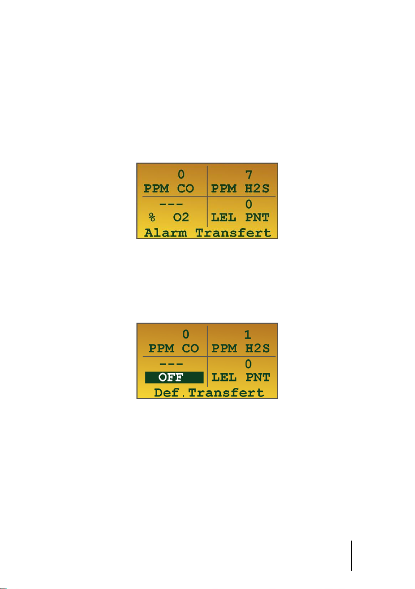
Alarm Transfer
By connecting the output of a BM 25 to the input of another BM 25, and so on, it is
possible to transfer alarms from instruments to instruments. This configuration is
particularly useful for perimeter monitoring. For example, it may be used to monitor a
fence by connecting the BM 25s on a daisy chain or to monitor a tank by connecting
the units in loop.
Refer to the Connections paragraph on page 14 for the wiring of the dry logic input or
the alarm relay output. The input and output can be configured using the COM 2100
software; see page 57.
Page 22
22
BM 25/25W
Instruction Manual
Connection of a manual call point
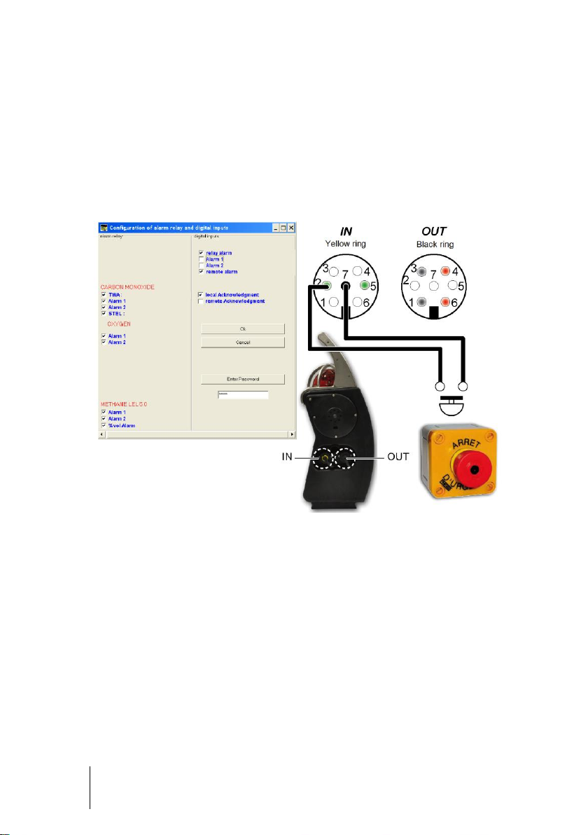
By connecting a manual call point to the input of a BM 25/25W, it allows the user to fire
the local audible and visible alarm in order to alert of an immediate danger (fire, man
down, evacuation, etc.). When the BM 25 is in wireless mode or wired to another BM
25/25W, the local alarm is reported to the other instruments (Alarm Transfer).
Figure 12: Push button connection (Example. Refer to COM 2100 software chapter on
page 57 for more details)
Page 23
3 – Operation
23
When starting up the BM 25/25W for the first time or after a period of
inactivity longer than one month, it is recommended to proceed a chargedischarge cycle. Moreover, keep in mind that all portable gas monitors
must be tested with gas before each day of use.
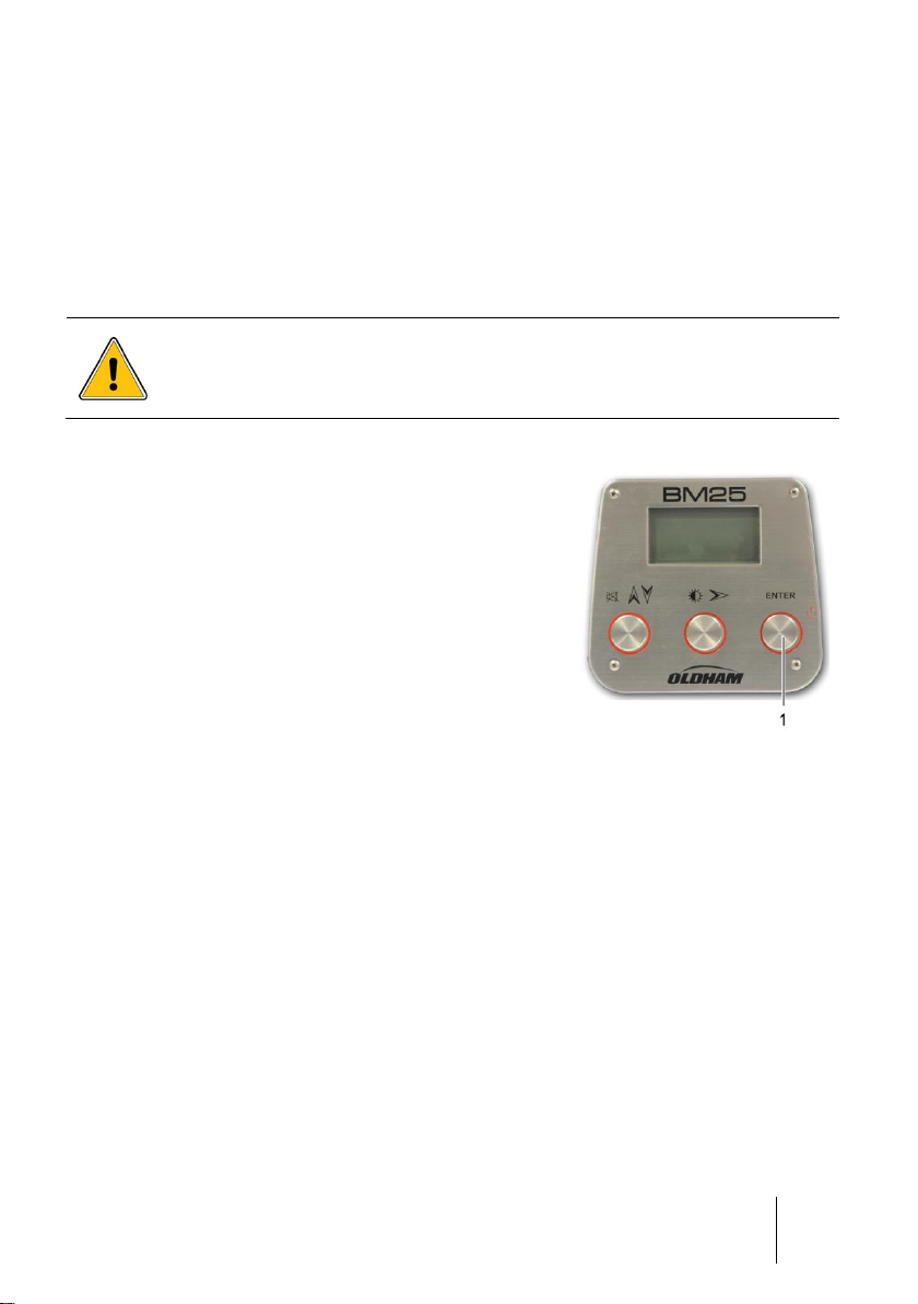
■ Press the Enter button (ref. 1).
■ Before displaying current measurements, the BM
25/25W performs visual and audible tests during a
few seconds and then displays:
- The OLDHAM logo,
- The software revision and the serial number,
- The alarm thresholds set for each measurement
channel.
■ Continue to paragraph Test Routine and
Calibration Overdue on page 24.
Note: During normal operation, the BM 25/25W flashes
every 2 minutes to indicate that it operates correctly.
This confidence flash can be canceled and the
frequency can be changed using the COM 2100
software; see page 51.
Figure 13: start-up in
standard mode by pressing
the Enter button
Chapter 3 | Operation
Start-up
Switching on the instrument
Selection of the flammable gas on start-up
On start-up, it is possible to change the calibration gas. This option allows the user to
measure a different flammable gas (acetone, methanol, etc.) from that which was
originally used (methane or pentane) to calibrate the instrument. This action allows the
instrument software to compensate and display more accurate readings. Note:
Accuracy for the re-selected gas type is +/- 15%.
Page 24

24
BM 25/25W
Instruction Manual
Step 1: Switch the instrument on
■ Press and hold the Acquit button (ref. 1). Press the
Enter button (ref. 2) to switch the instrument on.
■ Release both buttons.
■ When warm-up is complete, the BM 25/25W displays
the list of different gases. The gas currently selected
is highlighted.
Figure 14: press 1 and 2 to
select the calibration gas
Step 2: Select the reference gas
■ Use the Acquit button (Figure 14: press 1 and 2 to select the calibration gasref. 1)
to scroll down the list of gas. Thirty-one (31) combustible gases are available in the
library. Choose Other to select a gas for your specific needs.
Note: if a gas is not selected in the allotted time, the monitor will start in normal
mode without changing the reference gas.
■ Press the Enter button (ref. 2) to confirm your choice.
■ The BM 25/25W starts another test routine. Once the test is complete, the selected
gas is now the reference gas.
Test Routine and Calibration Overdue
During warm-up the BM 25/25W performs a self test and then starts gas measurement.
If the test is not completed successfully, the BM 25/25W goes into fault mode
(continuous audible and visual signal).
When the calibration date for a sensor is overdue, the BM 25/25W triggers a calibration
alert for the appropriate channel. This warning message may be dismissed and the
instrument will operate using its previous calibration settings; however, as the sensors
response may have diminished, the instrument should be recalibrated and tested.
Gas monitor positioning
Position the monitor vertically at the relevant location by taking into account the density
of the gases and the airflow.
Diffusion mode
In this configuration, the gas monitor is used without additional sampling device; the
sensors monitor the ambient atmosphere.
Page 25

3 – Operation
25
Sampling probes (rigid, semi-rigid or telescopic) and sampling tubing are
not antistatic. The user must take the necessary precautions to avoid
electrostatic discharges. In all cases, the user must prevent dangerous
electrostatic discharges using a metallic probe.
Warning (Hand Aspirator): The BM 25 series is designed to be used with a
built-in pump for remote sampling. A hand aspirator can be used for
indicative sampling, but it must be noted that when using a hand aspirator,
a reading error in the region of + 20% is possible. In addition, whereas the
pump can sample quickly and accurately with up to 30 meters of sample
line, the hand aspirator must only be used with up to 10 meters of sample
line and the sample time is extended. The sample line must be intact and
the proper flow established.
Aspirated mode (with pump option)
Remote sensing is possible with the internal electric pump option, or by using a hand
aspirator.
Using an electric pump
■ The internal pump is powered by the gas monitor's battery and starts automatically
when the sensors cover is applied (Figure 15: positioning the sensors cover (BM
25/25W equipped with an electric pump)ref. 1); this cover can be identified by its
hump (ref. 4).
■ Connect the sample line (ref. 2) to the gas inlet (ref. 3).
■ Wait a few seconds before reading the measurements. Any anomaly in the pump
system is indicated by an audible alarm and on the LCD display.
Figure 15: positioning the sensors cover (BM 25/25W equipped with an electric pump)
Page 26

26
BM 25/25W
Instruction Manual
Before each use of the electrical pump, check the seal by obstructing the
end of the sampling line until the Flow Fault alarm is triggered. Do not
forget to remove the sensors cover to return to diffusion mode.
Once the sampling is complete, remember to remove the sensors cover to
return to diffusion mode.
Using a manual pump
Figure 16: positioning the sensors cover (BM 25/25W non-equipped with an electric
■ Place and screw the cover over the sensors (Figure 16: positioning the sensors
■ Connect the sample line (ref. 2) to the gas inlet (ref. 3).
■ Wait for the measurements to stabilize before recording them; if measurements are
pump)
cover (BM 25/25W non-equipped with an electric pump)ref. 1); this cover has no
hump as previously mentioned (ref. 4).
recorded too soon, they may be over-estimated (combustible gases), or underestimated (oxygen).
Page 27
3 – Operation
27
Combustible gas concentration measurements can be affected by high or
low oxygen concentrations. Any reading rapidly changing from too high
(exceeding 100% LEL) to too low can in fact indicate a hazardous gas level
higher than the measurement scale.
Measurements
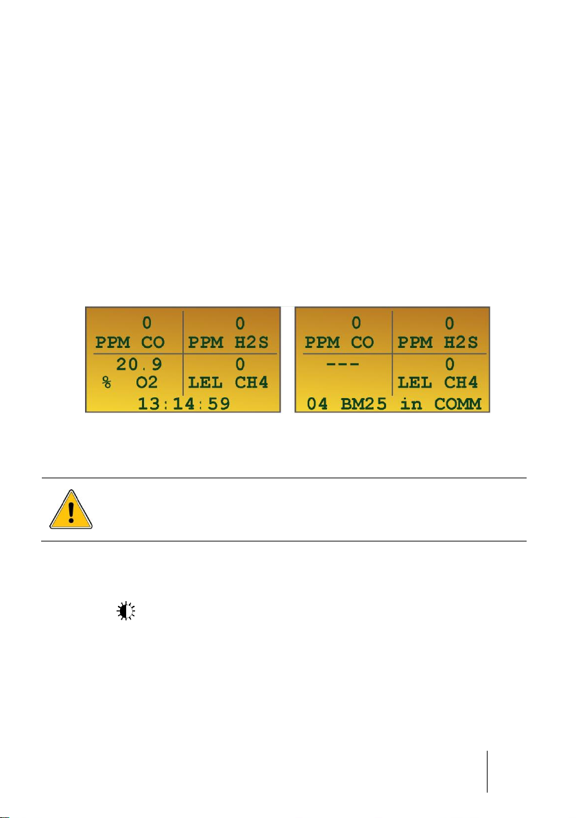
Reading measurements
The gas measurements are displayed at once on the LCD display in four separate
fields. In each field, the measurement is displayed as follows:
■ Gas concentration
■ Unit (ppm, % vol. or % LEL)
■ Gas type
■ In "5 gas" configuration, channel #5 is displayed alternately with channel #3 at
bottom left
At the bottom of the screen, time, alarm status and wireless communication status
(when applied) are displayed (see page 35).
Figure 17: on the left side, 4-gas monitor with no radio communication. On the right side,
3-gas monitor with radio ON.
Display management
Backlit
Press the button to read measurements in dark areas. Backlit turns off
automatically after 4 minutes. Display automatically illuminates on fault event or alarm
event.
Page 28

28
BM 25/25W
Instruction Manual
Displaying additional information
When the gas monitor is in normal operation, the user can access additional
information. Press the button repeatedly to scroll through the following screens:
■ Date (backlit is ON)
■ Area identification or user name (only if Roundsman option is activated; see
paragraph Roundsman function, below)
■ Remaining battery life (bargraph)
■ min/max values for each sensor
■ STEL value for each toxic sensor
■ TWA value for each toxic sensor
■ Maintenance menu which is password protected. To enter the maintenance menu
enter the 4-digit code using the and buttons.
Press the button to return to normal operation.
Roundsman function
If the Roundsman function has been activated, a list of names can be programmed
using COM 2100 software. This list can be viewed at any time by using the front keys
on the device.
To select a location or a user, follow these steps:
■ Press the button repeatedly until Current location/name appears.
■ Press Enter.
■ Scroll through the list using the and buttons.
■ Press Enter to confirm your selection.
■ Press to return to normal mode.
Reset the Min/Max
Press simultaneously the and buttons to reset the min/max values. The BM
25/25W sounds a beep to confirm the action.
Page 29

3 – Operation
29
Alarm information has priority over fault information.
Alarms
The BM 25/25W features visual and audible indicators:
■ Visual indicators: clear text messages on the display, one 360° red flashlight that is
visible from all directions
■ Audible indicators: two loud speakers (103 dB @ 1m)
Gas alarms
The gas monitor features:
■ Two instantaneous thresholds per channel for combustible, toxic or oxygen gases.
■ One falling and one ascending alarm for Oxygen (two falling alarms in option).
■ One STEL (Exposure Limit, country dependent) threshold per channel equipped
with a toxic gas sensor. The STEL value corresponds to the average of gas
measurements made over the last 15 minutes.
■ One TWA (Time Weighted Average, country dependent) threshold per channel
equipped with a toxic gas sensor. The TWA value corresponds to the average of
gas measurements made over the last 8 hours.
When an alarm is triggered, the monitor will fire its audible and visual indicators at
different frequencies depending on the alarm type:
■ Low Gas Alarm (Alarm 1): two-tone, slow (1 Hz).
■ High Gas Alarm (Alarm 2): two-tone, fast (2 Hz).
■ Alarm Transfer (repeated alarm): two-tone, very slow (0.5 Hz).
■ Fault: mono-tone, continuous (0 Hz).
The display will also indicate the alarm message(s) (ALARM 1, ALARM 2,
AL. TRANSFER, STEL, TWA, mini, etc.) as well as the gas measurement. In alarm
mode, the monitor will display the peak values (min or max depending on the gas type)
until acknowledgement button is pressed.
Gas Alarms Acknowledgement
Latching Alarms
The audible alarm will be silenced when the button is pressed. The visual alarm will
continue to blink while the gas measurement is outside the set limits. The visual alarm
will turn off automatically when the measurement is within the set limits.
If after two minutes the gas measurement is still outside the set limits, the audible
alarm will be automatically reactivated; this function can be deactivated by factory.
Page 30

30
BM 25/25W
Instruction Manual
Unlatching Alarms
In this configuration, audible and visual alarms will be acknowledged automatically,
without any action, as long as the gas measurement is within the set limits.
Fault alarms
Faults can be classified into two categories:
■ Sensor faults: out of range, low sensitivity, zero drift, etc.
■ Monitor faults (low battery, wireless communication fault, electronics fault, etc.).
In the event of a fault, the monitor sounds a continuous audible alarm and the flash is
steady. The corresponding fault message appears at the bottom of the display.
Examples of information which may be brought to the user's attention
Battery fault
■ Low battery: remaining battery life is less than 20 minutes. The BM 25/25W is still
operating, the audible signal can be silenced.
■ Battery fault: detection is no longer guaranteed. The audible signal cannot be
silenced.
> 100% LEL: Over-Range Flammable Gas Alarm Function
Applies to the combustible channel only. In this case:
■ Value on display is frozen.
■ Continuous audible signal cannot be silenced.
■ Visual flashlight is steady and cannot be turned off.
■ Combustible sensor (LEL) is powered down to prevent damages from
overexposure to gas.
Normal operating conditions can be restored by power cycling the BM 25/25W. This
operation must be performed outside the hazardous area.
Out of range
■ Negative Zero Drift (reading below -20% of full scale). This fault is automatically
resettable.
■ Over-Range (reading above 120% of full scale). This fault must be acknowledged
manually.
Alarm transfer
The gas monitor features:
■ one alarm relay output monitored by any channel and dedicated to alarm transfer
■ one dry logic input to trigger the local alarm
Page 31
3 – Operation
31
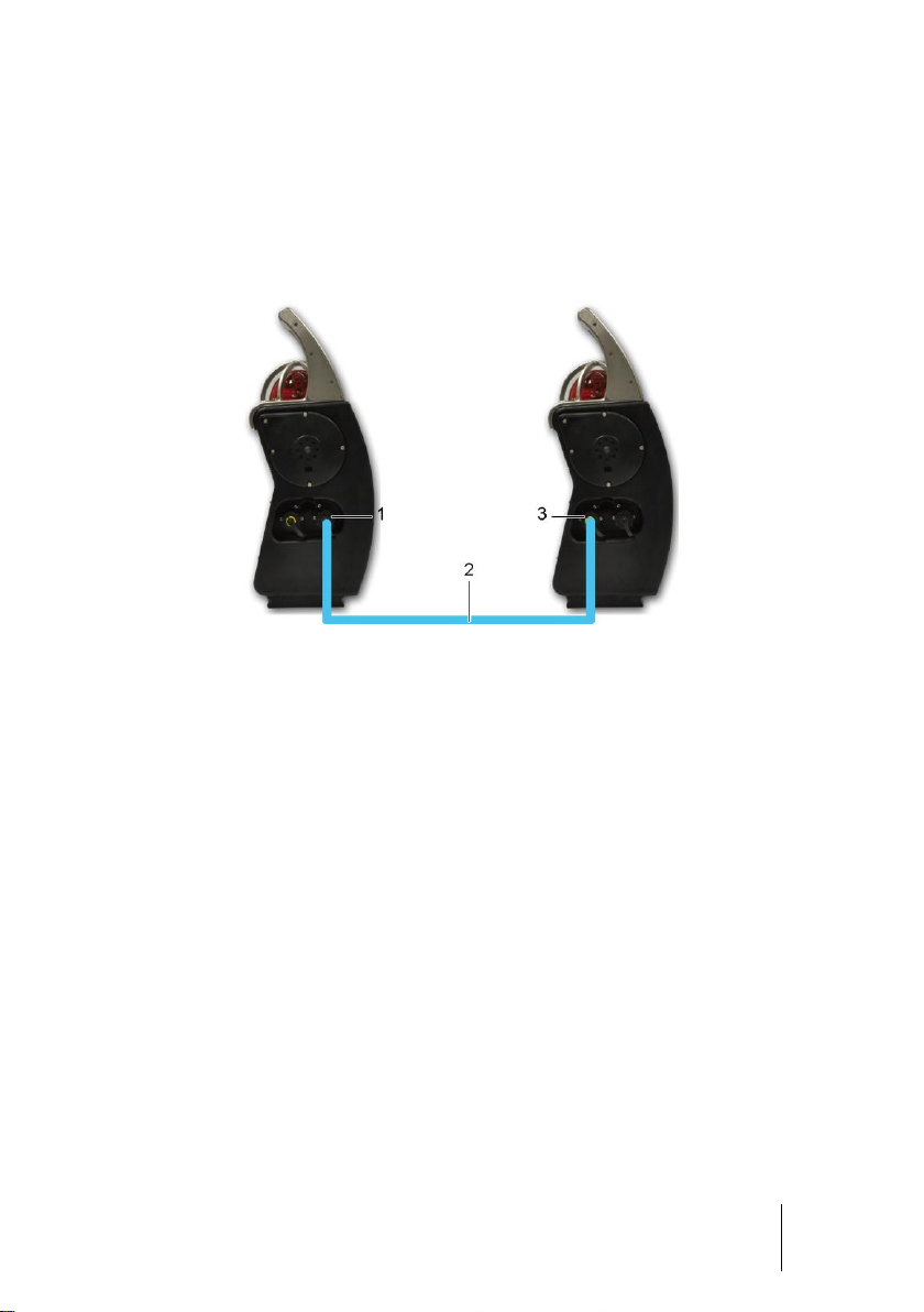
By connecting the alarm transfer cable (ref. 2), from the output of a BM 25 (ref. 1) to
the input (ref. 3) of another BM 25, and so on, it is possible to transfer alarms from
instruments to instruments. This configuration is particularly useful for perimeter
monitoring. For example, it may be used to monitor a fence by connecting the BM 25s
on a daisy chain or to monitor a tank by connecting the units in loop.
The input and output can be configured using the COM 2100 software; see page 57.
Figure 18: connection between two monitors
Page 32

32
BM 25/25W
Instruction Manual
Mandatory parameters for inputs/outputs:
■ Voltages and alternating currents: I = 150 mA max. - U = 30 V max.
■ Voltages and direct currents: I = 150 mA max. - U = 30 V max.
If the gas monitor is used in an explosive atmosphere, it is imperative to
consider output relay parameters, since contact must not impair the
intrinsic safety of the gas monitor. These parameters are mentioned in the
paragraph Special Instructions for use in explosive atmospheres on page
71. OLDHAM shall not, in any event, be liable for failure to follow
regulations.
Data transfer
The BM 25/25W stores gas measurements, alarm and fault events. Those data can
later be downloaded to a Personal Computer thanks to COM 2100 software.
Stored data
Once turned on, the BM 25/25W records data in time-stamped frames. The monitor
creates a new frame every time it starts up and every 24 hours. A frame contains:
■ Channels Information
■ Readings for each sensor at a defined recording interval (configurable).
■ Event logs for each channel:
- Alarm
- Fault
- Alarm Reset
- Maintenance operations (programming, calibration, sensor replacement,
zeroing).
Memory capacity
The gas monitor can store approximately 200,000 measurement points. When the
memory is full, oldest data are overwritten (FIFO).
Data storage
Data are stored as long as internal battery is charged. If the BM 25/25W is not used for
a long period of time and/or main battery is discharged, a lithium battery will take over
for a period of two years max.
Page 33

3 – Operation
33
■ To switch the instrument off, press the Enter
button (ref. 1) located on the front plate, for 3
seconds.
The instrument display starts a countdown from 3
to 1 before it asks to confirm. Release the Enter
button (ref. 1) and press again to switch the BM
25/25W off.
Figure 19: switch off by
pressing Enter button
Switching off the instrument
Page 34

34
BM 25/25W
Instruction Manual
Page 35
4 – Wireless Version
35
This product complies with FCC Maximum Permissible Exposure (MPE)
requirements when used with an approved antenna and the antenna is at
least 20 cm away from the user. Use of the product closer than 20 cm may
exceed the MPE limits. Use of any antenna other than approved antennas
will invalidate the certification of the product.
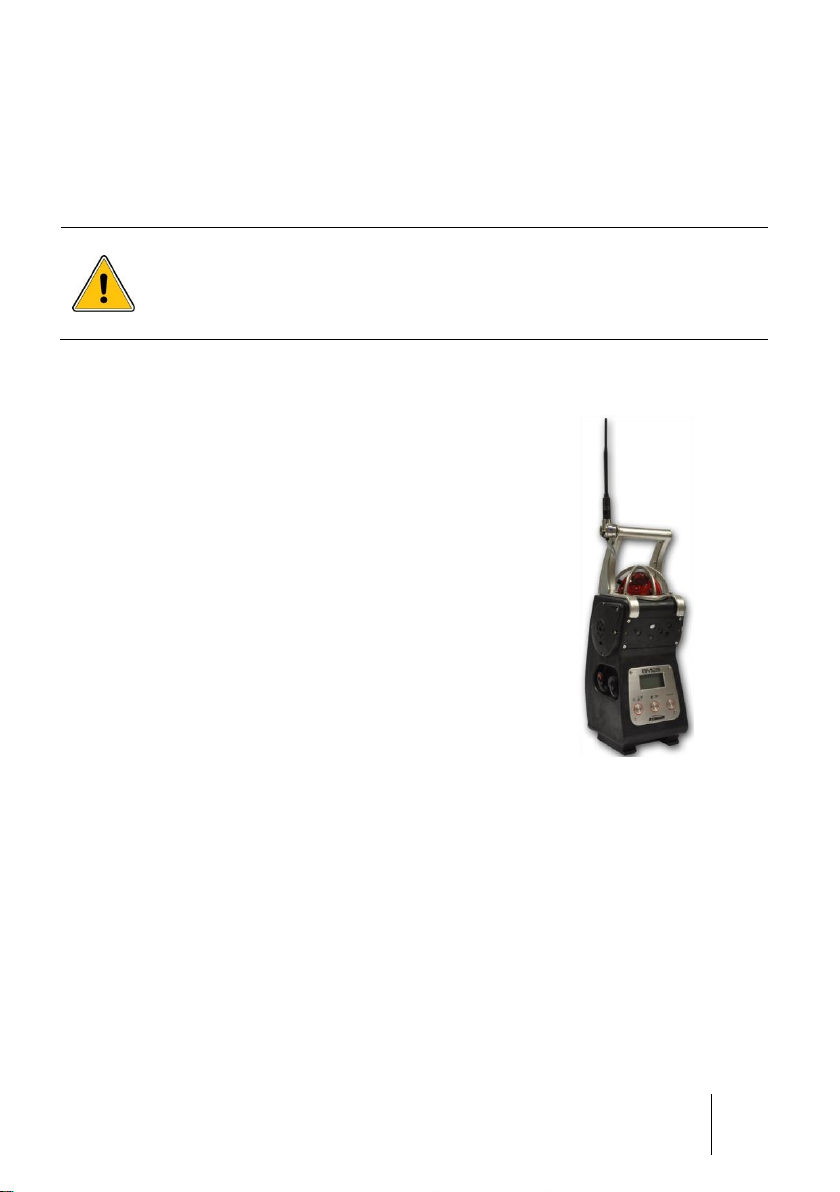
Available as an option, the radio communication allows
several BM 25Ws to communicate on the same network (BM
25 mode) or to send information wirelessly to a MX40 or X40
controller (CONTROLLER mode).
Wireless communication is made via a 2.4 GHz radio and
emitted power is less than 100 mW. Maximum distance
between two communicating devices is 3,300 feet line of
sight. Up to 30 BM 25Ws can be meshed on the same
network and up to 16 networks can coexist with no
interference.
The network topology used by the BM 25W is a MESH
network. In a mesh network all hosts are connected peer to
peer without central hierarchy, thereby forming a net-like
structure. Consequently, each node can receive, send and
relay data. This avoids having sensitive points, which in case
of failure, cut the connection of the network. If a node is
down, its neighbors go through another route.
Mesh topology allows fast and simple deployment, high
coverage versatility and high fault tolerance. It significantly
reduces installation and operating costs of networks. These
solutions reproduce the architecture of the Internet while
optimizing for wireless.
Figure 20 : Wireless
version, recognizable
by the presence of an
antenna
Chapter 4 | Wireless Version
Overview
BM 25 Mode
When in BM 25 mode, BM 25Ws send information regarding gas alarm and fault
status. Once a BM 25W is in gas alarm, the alarm is repeated on all other BM 25Ws on
the same network.
Page 36

36
BM 25/25W
Instruction Manual
Main BM 25W
Secondary BM 25W
Case
Cause
Flash
Siren
Flash
Siren
1.
Fault (no communication at
all, sensor fault, low battery,
etc.)
Steady
Yes
Steady
Yes
2.
At least one BM 25W does
not communicate
Steady
No
Steady
No
3.
Alarm 1
1 Hz
1 Hz
0.5 Hz
0.5 Hz
4.
Alarm 2
2 Hz
2 Hz
0.5 Hz
0.5 Hz
Two-way
communication
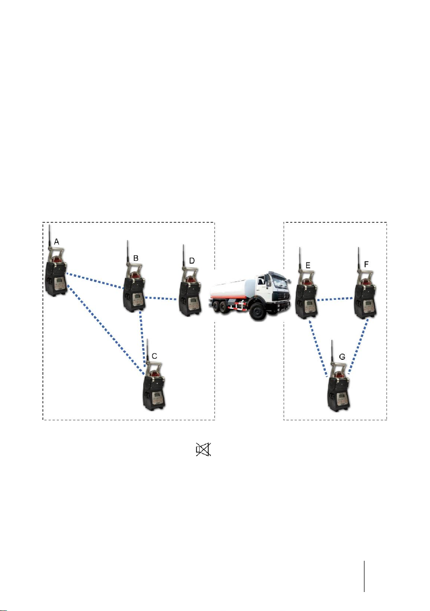
Figure 21 : In the example above, BM 25W tag G communicates with E and F. In the event
of a loss of communication between G and F, E still ensures the communication to the
rest of the network. If G goes into gas alarm or fault condition, all BM 25Ws on the
network will report a corresponding alarm
Alarm sequence differs depending on whether a BM 25W sends information (gas alarm
or fault) or receives information (alarm transfer). This allows for quick identification of
the BM 25W in alarm condition so that the appropriate action can be taken. Although
there is no hierarchy in a mesh network, the unit in alarm and the unit reporting the
alarm are referred to later in the manual as 'main’ and ‘secondary’ BM 25W,
respectively.
Table 1 : ‘Alarm’ mode – Table of events
Page 37
4 – Wireless Version
37
Gas alarm Transfer
In the event one BM 25W goes into a gas alarm, all secondary BM 25Ws will display «
Al. Transfert » as shown below. Press the “acquit” button to silence the audible alarm.
The BM 25W strobe will continue to flash until the alarm event has ended. The audible
alarm will reactivate after 5 minutes if the alarm event is still active.
Note that if a second BM 25W had to fire a gas alarm, then this BM 25W would pass
from ‘secondary’ to ‘main’ status and would sound at 1 or 2 Hz depending on the alarm
level being reached. The secondary BM 25Ws would not immediately reactivate the
local siren.
Figure 22 : Secondary BM 25W reporting an ‘Alarm Transfer’ condition
Fault Transfert
In the event one BM 25W goes into fault condition, secondary BM 25Ws will display on
their LCD screen the message « Def. Transfert » as shown below. This fault condition
is not acknowledgeable and is automatically cleared as soon as the main BM 25W
goes back into a normal operating condition.
Figure 23 : Secondary BM 25W reporting a ‘Fault Transfer’ condition
Page 38

38
BM 25/25W
Instruction Manual
Two-way
communication
Controller Mode
In Controller mode, BM 25Ws send fault status, alarm status and gas measurements to
the controller. As soon as one BM 25W fires an alarm, the controller relays the gas
alarm information to all BM 25Ws on the same network that then turn in Alarm Transfer
mode.
Figure 24 : In the example above, BM 25Ws E and F are the last links between the
controller and the rest of the network. If communication between BM 25W F and MX 40
fails, then BM 25W E continues to provide communication between the BM 25W network
and the controller. If BM 25W A goes into gas alarm or fault condition, then MX 40
receives information and passes the gas alarm on all others BM 25Ws
The alarm sequence differs depending on whether a BM 25W sends information (gas
alarm or fault) or receives information (alarm transfer). This allows for quick
identification of the BM 25W that is in alarm so that appropriate action can be taken.
Page 39
4 – Wireless Version
39
Main BM 25W
Secondary BM 25W
Controller
Case
Cause
Flash
Siren
Flash
Siren
Channel
status
1.
Fault (no
communication
at all, sensor
fault, low
battery, etc.)
Steady
Yes
No
No
Fault
2.
Alarm 1
1 Hz
1 Hz
0.5 Hz
0.5 Hz
Alarm 1
3.
Alarm 2
2 Hz
2 Hz
0.5 Hz
0.5 Hz
Alarm 2
Tableau 2 : Controller Mode – Table of events
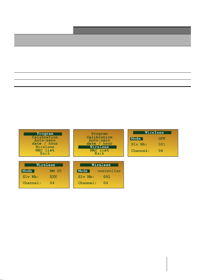
Start-up
From the Maintenance menu (see Chapter 5), choose Wireless. Leave it to 'OFF' if you
do not want to activate the radio function. Select 'BM 25' or 'Controller' according to the
chosen operation mode (see above).
Figure 25 : Wireless mode screenshots
■ In BM 25 mode: only the network ID (Channel) must be set between 0 and 15.
Address number (Slv Number) is not editable and is set to 'XXX'. In this mode, it is
not necessary to assign an address as the network is automatically built in by using
the MAC
■ In Controller mode: set the BM 25W address Slv Nb between 1 and 30 max. and
the network ID Channel between 0 and 15.
(*) MAC (Media Access Control): unique identifier assigned to network interfaces. Each BM 25W
has its own unique MAC address.
WARNING
(*)
addresses of each device.
Page 40
40
BM 25/25W
Instruction Manual
■ It is important that all BM 25Ws intended to be on the same network have the same
network ID.
■ In Controller mode, two BM 25Ws cannot share the same address otherwise you
will get a fault.
Once wireless mode is activated (‘BM 25’ or ‘Controller’ mode), you have 5 minutes to
declare another BM 25W on the same network. When the time is gone and no
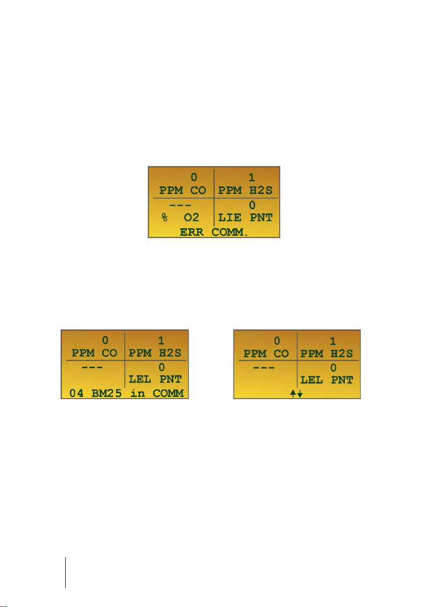
communication is established, BM 25W shows 'COMM ERR' and goes into fault (see
case #1 from table of events).
Figure 26 : COMM ERR, no communication is established
Thereafter, in normal operation, each BM 25W sends its information over the network
every ten seconds. If a BM 25W goes into gas alarm or fault condition, then the
information is immediately sent without waiting ten seconds. In BM 25 mode, the
number of BM 25Ws that are communicating on the network is shown at the bottom of
the display screen (example 4 shown below).
Figure 27a – BM 25 mode : Four BM
25Ws communicate with each other
on the same network
When in BM 25 mode, BM 25W displays the radio signal strength as indicated below in
figure 27c. It corresponds to the average of signals received from all BM 25Ws that the
BM 25W you are looking at is communicating with.
Figure 27b – Controller mode : BM 25W
is communicating with the controller
Page 41
4 – Wireless Version
41
Figure 27c – BM 25 mode : Radio Signal Strengh
When is displayed, the BM 25W has 100% of the signal and the radio
communication is very good.
When is displayed, the signal strengh is less than 20% although BM 25Ws are
still communicating.
When is displayed, no communication is established, BM 25W shows 'COMM
ERR' and goes into fault (see case #1 from table of events).
Adding a BM 25W on an existing network
In BM 25 mode, the network is automatically built. Each BM 25W with the same
network ID is automatically included as long as it communicates with at least one BM
25W belonging to the same network.
To add a new BM 25W to an existing network, simply turn the unit on, activate the
radio communication and, if applicable, set the network ID.
In MODBUS mode, you must set the address number (Slv Nb), set the network ID
(Channel) and configure, if applicable, a new input on the controller.
Removing a BM 25W from an existing network
In BM 25 mode
■ turn the unit off
■ or deactivate the radio module from the maintenance menu.
In both cases, before communication stops, the BM 25W broadcasts a last message to
inform the other BM 25Ws on the same network that it will be removed.
In Controller mode
To remove a BM 25W from an existing network, just switch the controller channel off,
then turn the BM 25W off or deactivate the radio module if you still need to use the BM
25W in local.
Page 42

42
BM 25/25W
Instruction Manual
Self-healing
NOTE : This section covers the ‘BM 25’ mode only.
Each BM 25W broadcasts a message every 10 seconds. Using the example shown
below, if BM 25W tag A receives no message from BM 25W tag B for more than 2
minutes, then B is considered as missing by A which turns into fault mode (case No. 2
– Table of alarms) and transfers the information to all other BM 25Ws on the network.
Note that BM 25W tag B can act the same if it receives no information from A. Number
of BM 25Ws that do not communicate anymore is displayed on each BM 25W referring
a communication fault. This number may differ depending on the BM 25W you are
looking. Here below, one BM 25W out of four is no longer communicating.
Figure 28 : One BM 25W out of four does not communicate
In case of communication failure, the network tries to reestablish communication every
ten seconds.
In BM 25 mode, if a BM 25W does not respond or if the network is split, then it is
possible to ignore this fault and to continue to work by the time of the restoration of the
network.
Page 43
4 – Wireless Version
43
In the example above, BM 25W (unit D) is the only communication link between A, B,
C and E, F, G. If BM 25W (unit D) had a fault (low battery for instance) or if an
obstacle were to disrupt communication between D and E or D and B, then all BM
25Ws would report a fault failure (steady flashlight according to case No. 2 – see
table of alarms).
IMPORTANT :
■ Note that the gas detection remains effective and that BM 25W (unit D) would still
locally alarm in the presence of gas. It is the same for each BM 25W on the
network. Only the alarm would not be transferred to the whole network.
■ To ensure maximum network reliability, a BM 25W should always communicate
with at least two neighbors.
Figure 29 : group concept (read details below)
A long press on the « acquit » button forces the system to a new identification of
the nodes present on the network. BM 25Ws that do no communicate are ignored
without triggering a fault condition. In the example above, the communication between
D and E is down. A long press on the « acquit » button of BM 25W (unit D) resets the
network. All BM 25Ws communicating with D automatically launch a new identification
in turn. On one side, BM 25Ws A, B, C and D discover each other and form a first
group. On the other side, BM 25Ws E, F and G still report a communication failure
since they do not receive data from the BM 25Ws of the newly formed group. A long
press on the « acquit » button of one BM 25W (unit E, F or G) clears the list of BM
Page 44

44
BM 25/25W
Instruction Manual
25Ws on the network and forces to a new identification. Similarly as above, BM 25Ws
(units E, F and G) form a second group.
IMPORTANT :
■ The two groups run independently and alarm or failure events from one group
cannot be transferred to the other group.
■ When the obstacle (the truck in our example) is gone, the communication between
E and D resumes automatically without the need to restart identification. The two
groups merge together to form only one group.
To start a new identification, keep pressing the « acquit » button for 3 seconds. The
display successively shows 3, 2, 1 then « confirm ». Release the « acquit » button and
press again.
Figure 30 : reset sequence of a group of BM 25Ws
NOTE :
■ When a new identification has started, communication errors are inhibited for one
minute.
■ Once the network healing is completed, it is possible that one or several BM 25Ws
remain isolated and stay in fault mode (case No. 1 – Table of alarms). To
acknowledge this failure, turn the unit off or disable the radio communication from
the maintenance menu.
Adding a new BM 25W to the network at a smart location overcomes the obstacle and
restores the communication between the two groups which then merge together. This
healing is automatic as long as BM 25W (unit H) belongs to the same network (same
'Channel' ID).
Page 45

4 – Wireless Version
45
Figure 31 : bypassing an obstacle by adding a new BM 25W (H)
Mac list menu
NOTE : This section covers the BM 25 mode only.
Available from the Maintenance menu (see Chapter 5), the « MAC List » menu allows
the user from any BM 25W belonging to the network to get the MAC
BM 25W on the network and its particular status.
(*) MAC (Media Access Control): unique identifier assigned to network interfaces. Each BM 25W
has its own unique MAC address.
(*)
address of each
Figure 32 : MAC List menu
Page 46

46
BM 25/25W
Instruction Manual
When in the « MAC List » menu, the first address displayed and aligned to the right is
the address of the BM 25W you are currently looking at (here 0487D2). Up to 6 MAC
addresses can be displayed per page.
Figure 33 : List of the MAC addresses present on the network
A BM 25W in gas alarm mode is shown with the status ‘A’ (here, BM 25W with address
No. 04C392 is in alarm). A BM 25W in fault mode (low battery for instance) is shown
with the status ‘D’ (here, BM 25W with address No. 0487D1 is in fault).
When a BM 25W is no longer communicating on the network, its address appears in
reverse video. See “SELF-HEALING” parapragh for trouble shooting.
Figure 34 : Status of each BM 25W on the network
Figure 35 : BM 25W with MAC address No. 0487D1 does not communicate
Page 47

5 – Maintenance
47
The gas monitor is factory-programmed to display a maintenance alert if a
calibration has not been performed in the last twelve months (the message
Calibration due will appear on the screen).
The operations explained in this chapter must be performed by authorized,
qualified personnel only, as they could adversely affect detection safety.
Chapter 5 | Maintenance
Gas monitors are safety instruments. Recognizing this fact, OLDHAM recommends
that a functional test be performed on every portable gas monitor prior to each use. A
functional test involves injecting a gas of sufficient concentration at the sensor level to
trigger pre-set alarms. This test does not, in any event, replace a full calibration of the
sensors.
If a gas monitor does not respond correctly to a gas test, a full calibration with a
calibration gas is mandatory.
These recommendations are consistent with applicable industry safety protocols and
with the standards and directives relative to the safety of industrial sites. OLDHAM is
also not responsible for procedures performed onsite.
Accessing maintenance menus
When in normal operation mode,
■ Scroll to parameters using the / button until a request for an access code
and 0000 is displayed.
■ 0018 is the default code. Scroll to each digit with the button. Use button to
select the right number and confirm access code with the ENTER button.
Page 48

48
BM 25/25W
Instruction Manual
The list of available menus will then be displayed:
■ Program
■ Calibration
■ Auto-zero
■ date / hour
■ Wireless (see Chapter 4)
■ MAC List (see Chapter 4)
■ Exit
Program Menu
This is used to:
■ Activate/Deactivate a channel
■ Display sensor information (gas type and measurement range)
■ When using a catalytic sensor, to select the reference gas from the library (see
table below) or enter a correlation factor and to program alarm set points
■ When using an oxygen sensor, to set the low (descending) and high (rising) alarm
thresholds or 2 low alarm levels if this option was selected
■ When using a toxic gas sensor, to set alarm thresholds
The coefficients are given for information in relation to CH4 with an LEL of 5.0%
volume, and are automatically used by the monitor during calibration or when changing
the reference gas. If the combustible gas to be detected is not in this list, you can use
the Other window by selecting a coefficient provided by OLDHAM (contact us).
Page 49

5 – Maintenance
49
Gas
Molecular
formula
LEL 1
LSE 2
Vapor
density
Coef. /
CH4.
Recommended
calgas
Abbreviation
(French)
Ethyl acetate
C4H8O2
2.1 %
11.5 %
3.0
1.35
But/Prop
AET
Acetone
C3H6O
2.15 %
13 %
2.1
1.55
But/Prop
ACO
Acetylene
C2H2
1.5 %
100 %
0.9
1.1
But/Prop
ACY
Butadiene
C4H6
1.4 %
16.3 %
1.85
1.25
But/Prop
BUD
Butane
C4H10
1.5 %
8.5 %
2.0
1.6
But/Prop
BUT
Butanone
C4H8O
1.8 %
11.5 %
2.5
1.75
But/Prop
BUN
Dimethylether
C2H6O
3.0 %
27.0 %
1.6
1.55
But/Prop
DIM
Unleaded petrol
Mixture
1.1 %
6 %
3 to 4
3.0
But/Prop
ESS
Ethanol
C2H6O
3.3 %
19.0 %
1.6
1.15
But/Prop
ETA
Ethylene
C2H4
2.7 %
34.0 %
0.98
1.0
But/Prop
ETY
G.P.L.
Prop+But
1.65 %
9.0 %
1.85
2.05
But/Prop
GPL
Diesel
Mixture
0.6 %
6.0 %
> 4
5.00
But/Prop
GSL
Natural gas
CH4
5.0 %
15.0 %
0.55
1.05
CH4
GNT
Hexane
C6H14
1.2 %
7.4 %
3.0
2.36
But/Prop
HEX
Hydrogen
H2
4.0 %
75.6 %
0.069
0.80
But/Prop
H2
Isobutane
C4H10
1.5 %
15 %
2.0
1.6
But/Prop
ISB
Isopropanol
C3H8O
2.15 %
13.5 %
2.1
1.6
But/Prop
ISP
Methane3
CH4
5.0 %
15.0%
0.55
1.00
CH4
CH4
4.4 %
1.14
Methanol
CH3OH
5.5 %
44.0 %
1.1
1.0
But/Prop
MTL
Methylamine
CH3NH2
4.9 %
20.7 %
1.1
2.0
CH4
MAM
Propylene oxide
C3H6O
2.3 %
37.0 %
2.0
2.0
But/Prop
OPR
Ethylene oxide
C2H4O
2.6 %
100 %
1.5
2.1
But/Prop
ETO
Pentane
C5H12
1.4 %
8.0 %
2.5
1.70
But/Prop
PNT
Propane
C3H8
2.0 %
9.5 %
1.6
1.3
But/Prop
PRO
Propylene
C3H6
2.0 %
11.7 %
1.5
1.2
But/Prop
PRY
Toluene
C7H8
1.2 %
7.0 %
3.1
2.05
But/Prop
TOL
White spirit
Mixture
1.1 %
6.5 %
> 2
5.0
But/Prop
WSP
Xylene
C8H10
1.0 %
7.6 %
3.7
2.5
But/Prop
XYL
(1) Lower flammable limit.
(2) Upper flammable limit.
(3) The LEL adopted value for methane varies by country. The monitor integrates two different LEL values for
CH4 (4.4% vol. and 5.0% vol.)
List of pre-programmed combustible gases with coefficients
Page 50

50
BM 25/25W
Instruction Manual
When battery is low, the user is notified with a Battery fault message
before losing all stored data. The battery must then be replaced. This
operation should only be performed by OLDHAM or OLDHAM approved
personnel.
Sensor calibration menu
Calibration consists of a zero adjustment in clean air (free from any gases that could be
detected by the gas monitor), as well as a sensitivity adjustment using calibration gas
of concentration between 15% and 100% of the full sensor range. Test gas shall be
applied at a 60 liters per hour flow rate.
Auto-adjustment menu
Allows to zero each sensor.
Date and time management menu
To set the instrument’s built-in-clock since saved data and event logs are time
stamped.
Loss of date and time
An on-board lithium battery keeps date and time saved in memory (see paragraph
Data storage on page 32) when the main battery is drained or when the monitor is
turned off. Expected lithium battery’s runtime is 2 years.
Radio communication menu
This menu allows the user to:
■ Switch the radio on and off
■ Select the operation mode (BM25 or controller mode)
■ Set the BM 25W Modbus address (when in controller mode)
■ Set the network ID
MAC List menu
When in wireless mode, this menu displays:
■ The monitor's MAC address
■ MAC addresses of all BM 25Ws belonging to the same network
■ Status of each BM 25W on the same network
Exit menu
Return to normal mode.
Page 51

6 – COM2100 software
51
Chapter 6 | COM2100 software
Subject
This software is for settings and service purpose. It features:
■ Channels settings
■ Diagnostics in case of failure
■ Instrument settings
■ Sensors calibration
■ Calibration and Control certificates
■ Datalogging management
Through its infrared port (ref. 1), the BM 25/25W can be connected to a computer by
using a connection cable (ref. 2 and 3).
Figure 36: interconnection cable and welcome screen
Page 52
52
BM 25/25W
Instruction Manual
Once COM 2100 is running, the BM 25/25W
connects automatically and a window pops up as
indicated in figure Figure 37: the parameter
programming menu.
Follow the steps below:
■ Set communication parameters as necessary
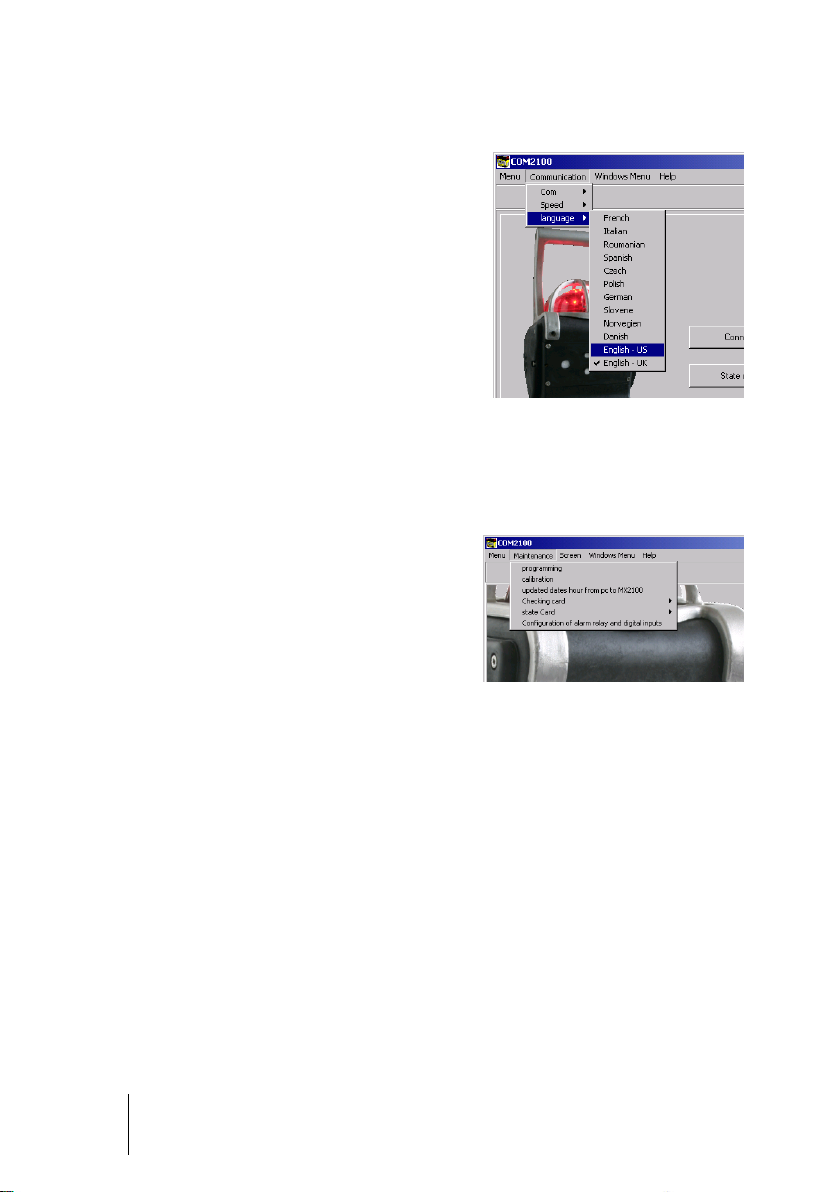
(port, speed, language)
■ Click the Connect button.
Figure 37: the parameter
programming menu
Follow the steps below:
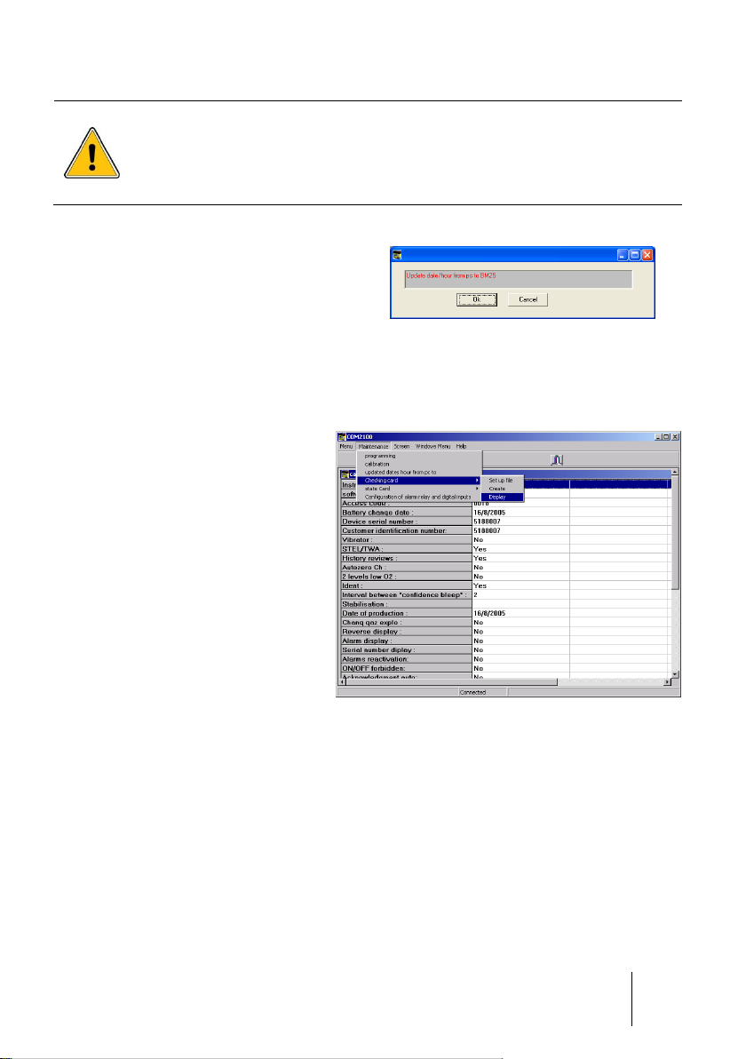
■ From the main list of menus, access the
Maintenance menu.
Options are:
■ Program: see page 53
■ Calibration: see page 54
■ Time Setting: see page 55
■ Monitoring report: see page 55
■ Status report: see page 55
Figure 38: Maintenance menu
Gas monitor connection
Maintenance menu
Page 53

6 – COM2100 software
53
Programming Menu
Proceed as follows:
■ From the Maintenance menu (Figure 38), select Programming
■ The screen here below pops up
Figure 39 - Program menu screen
Channel settings
■ Access is password protected. The default code is 1000 (to change this code, see
paragraph Screen menu on page 58).
■ The first column, Activated (top left) allows the user to switch on/off a channel. The
second column Present allows the user to display (or not to display) a channel that
has been switched off, e.g. O2 OFF (or blank screen).
- Click Confirm to save the modification.
Alarm settings
Select the channel from the dropdown list (Channel selection - Figure 39):
■ Edit alarm threshold values
■ Click Alarm validation to save your settings.
Page 54

54
BM 25/25W
Instruction Manual
■ Access is password protected. Select the
channel fitted with the catalytic sensor
(Channel selection, see Figure 39).
■ Select the Reference Gas as necessary:
- Choose another gas from the list and
click on Programming combustible gas
(Figure 40: programming combustible
gas.
- Click Exit.
Figure 40: programming
combustible gas
■ From the Maintenance menu
(Figure 38), select Calibration.
■ Choose the sensor to calibrate.
■ Set the maintenance interval.
■ Enter the calibration gas
concentration value (shall be
between 15 and 100% of the
sensor range).
■ Click Zero to start the procedure.
Follow the software instructions.
You will be asked first to inject
Zero Air and then Calibration
Gas.
Figure 41: Calibration menu
Once the calibration is complete,
click OK to validate. If you miss
something during the calibration,
click Cancel and start the calibration
again.
Once you have confirmed the
calibration is complete, the BM
25/25W will notify whether the
sensor passed or failed the
calibration. In the event of a failure,
repeat the calibration process or
proceed with the sensor
replacement.
Figure 42: confirming Calibration
Reference Gas settings
Calibration menu
Page 55
6 – COM2100 software
55
Oldham recommends using pure gases: using mixed gases can alter the
accuracy of gas measurements due to cross interferences between the
sensors.
The calibration gas concentration value shall be between 15% and 100%
of the measurement range.
■ From the Maintenance menu
(Figure 38), select the option
Update the BM 25/25W date and
time from a PC.
■ Click OK to validate and exit.
Figure 43: the Time Settings menu
Follow the steps below:
■ From the Maintenance menu
(Figure 38), select ’Checking
card’.
■ Fill in the fields (user's
information for instance)
■ Create the monitoring report
(.ctr file)
■ From the PC (COM 2100 files)
open the files to edit or print.
Figure 44: the Monitoring Report menu
Date and Time Settings
Monitoring Report menu
Page 56

56
BM 25/25W
Instruction Manual
Step 1
Step 2 and 3
Step 4
Example:
Status Report menu
From the Maintenance menu (Figure 38), select ’State card’ and follow the same steps
as described in the Monitoring Report menu (.etx files).
Page 57

6 – COM2100 software
57
■ Set relay output and the logic input by
checking the different boxes (Figure 45).
Reference 1
Alarm relay output settings. In this example
all CO, O2 and LEL alarms will trigger the
relay output.
Reference 3
To set the BM 25/25W modes when logic
input is activated (set to 1).
- Alarm relay: internal relay output is
activated
- Alarm 1: BM 25/25W will turn in Alarm 1
mode
- Alarm 2: BM 25/25W will turn in Alarm 2
mode
- Remote alarm: BM 25/25W will turn in
Alarm Transfer mode
Reference 4
Alarm acknowledgment
- Local acknowledgment: alarms must be
acknowledged from the gas monitor
keyboard.
- Remote acknowledgment: when on a
network (wired or wireless), local alarms
can be acknowledged from another BM
25/25W.
■ Click OK to confirm.
Figure 45: alarm output relay and
logic input settings
Alarm relay configuration and logic inputs
Page 58
58
BM 25/25W
Instruction Manual
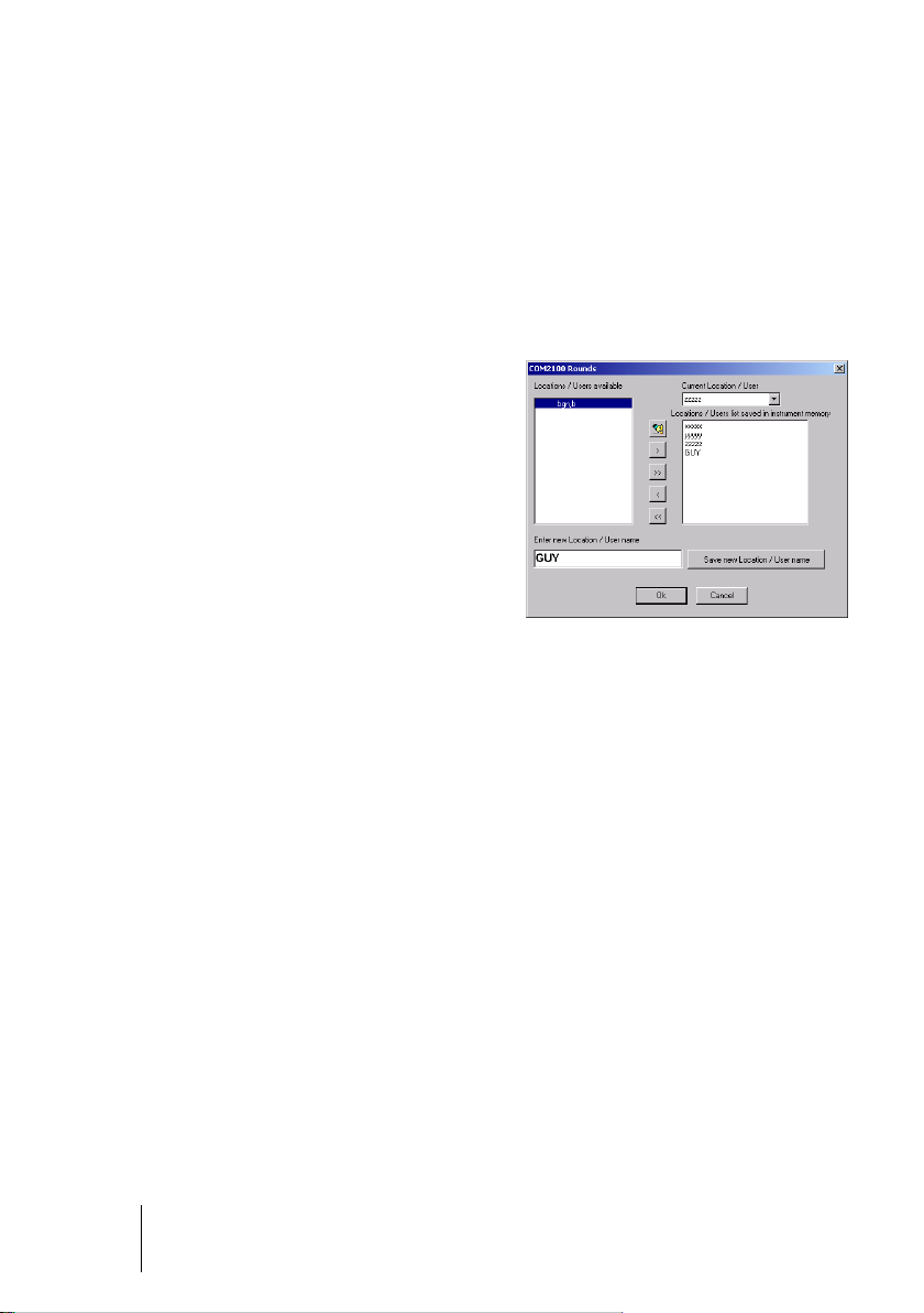
■ To create a new entry, fill in the field Enter
new Location/User name.
■ Click on Save new Location/User name.
The new entry appears in the window on
the left (Locations/Users available).
■ To add an (all) user/location to the BM
25/25W, select an input from the left and
click on the ‘>’ (>>) icon.
■ To remove an user/location from the BM
25/25W, select an input from the right and
click on the ‘<’ (>>) icon.
■ Click OK to confirm.
Figure 46: list of users/locations
Screen menu
This menu displays the log events, gas measurements and device’s configuration.
The password to access the maintenance menu is 0018 and software access code is
1000. Those passwords are user configurable.
Lists of users and/or locations can be created from this menu. This function allows to
assign log events by user or location.
List of Users/Locations management
Page 59

7 - Technical Specifications
59
Function
Manufacturer :
OLDHAM
Function:
Area Gas Monitor
Type:
BM 25 and BM 25W (wireless)
Gas
Configuration:
One to four sensors (catalytic, electrochemical, infrared
or PID sensors)
Gases detected:
Combustible, toxic and oxygen
Measurement:
Continuous on all sensors in operation
Sensors:
Plug & Play
Display
■ Graphic LCD with backlit
■ Clear messages
■ Flip-Flap function
Various alarms
Operations check:
■ Self-test at start-up
■ Unit flashes every 2 minutes (Confidence test)
Alarm thresholds:
■ Combustible: 2 adjustable instantaneous thresholds
in 0-60 % LEL range
■ Oxygen: two adjustable instantaneous thresholds
over the sensor's entire measuring scale (overoxygenation and under-oxygenation) or two optional
under-oxygenation thresholds
■ Toxic (per sensor): two adjustable instantaneous
thresholds over the sensor's entire measuring scale
■ Toxic (per sensor): two adjustable averaged
thresholds over the sensor's entire measuring scale
for STEL and TWA monitoring
Gas Alarm:
■ Visual and Audible alarm (1Hz and 2Hz)
■ Clear message on the display
Chapter 7 | Technical Specifications
Gas monitor
Page 60

60
BM 25/25W
Instruction Manual
Sensor fault:
■ Visual and Audible alarm (continuous)
■ Clear message on the display
Battery fault:
■ Visual and Audible alarm (continuous)
■ Clear message on the display
Inputs and outputs
Inputs/Outputs
■ RS232 infrared link
■ Alarm relay output
■ Fault relay output
■ Dry Logic input
■ Optional Wireless Communication (2.4GHz - 100 mW)
Additional software
Additional software:
Maintenance software COM 2100
Power supply
Power Supply:
NiMH rechargeable battery pack
Battery life in hours
(excluding alarms and as a
function of the number of
sensors):
Configuration
Without radio
module (hours)
With radio
module (hours)
1 catalytic and 2
infrared
40
35
1 catalytic and 1
infrared
70
50
1 catalytic and
several Tox
100
65
Only Tox sensors
170
135
Charging Time:
4.5 hours
Weight and dimensions
Weight:
6.85 kg
Dimensions:
470 x 180 x 190 mm (H x W x D)
Certification
Ingress Protection:
IP 66
Certifications:
CE, ATEX, IECEx, FCC
Page 61

7 - Technical Specifications
61
Methane
(CH4)
Methane
(CH4)
Methane
(CH4)
Sensor reference
6314064
6313888
6313889
Standard range (1)
0 - 100% LEL CH4
0 - 100% LEL CH4
0 - 100% vol
Measurement principle
Infrared
Catalytic
Catharometric
Display resolution(1)
1 % LEL
1 % LEL
1% v/v
Accuracy (2)
2 2 2
Repeatability (3)
± 2 % LEL
± 1 % LEL
± 1% vol
Zero/Span drift (4)
1 / 2
0.5 / 5
0.2 / 2
Response time (5)
< 30s
< 20s
< 20s
Temperature (6)
-20°C to +55°C
-20°C to +50°C
-20°C to +50°C
Relative humidity and
pressure range (7)
■ 0 – 99 % RH
■ 1 bar ± 10 %
■ 0 – 99 % RH
■ 1 bar ± 20 %
■ 0 – 99 % RH
■ 1 bar ± 20 %
Service life (8)
> 60 months
48 months
60 months
Storage conditions and
maximum storage time
(9)
■ 4°C to +20 °C
■ 10-60 % RH
■ 1 bar ± 10 %
■ 6 months
maximum
■ -40°C to +40 °C
■ 10-60 % RH
■ 1 bar ± 10 %
■ 6 months
maximum
■ -40°C to +40 °C
■ 10-60 % RH
■ 1 bar ± 10 %
■ 6 months
maximum
Warming-up delay (10)
300s
30s
30s
Notes
Hydrogen cannot be
detected with IR
sensor.
■ Measurement is
underestimated
if oxygen level is
< 10 %.
■ Exposure to high
levels of silicon or
sulfur vapors may
damage the sensor.
■ The monitor is
sensitive to the
majority of
explosive gases.
Sensors
Non-exhaustive list.
Table No. 1
Page 62

62
BM 25/25W
Instruction Manual
Isobutylene
Oxygen
(O2) 2 years
Oxygen
(O2) 1 year
Sensor P/N
6313998
6313780
6313817
Standard range (1)
0 – 1500ppm
isobutylene
2 - 30% volume
2 – 30% volume
Measurement principle
PID
Electrochemical
Electrochemical
Display resolution(1)
1ppm
0.1% v/v
0.1% v/v
Accuracy (2)
150
0.3% v/v
0.3% v/v
Repeatability (3)
0.1% v/v
0.1% v/v
Zero/Span drift (4)
0.2 / 2
0.2 / 2
Response time (5)
< 20s
< 10s
< 10s
Temperature (6)
0°C to +40°C
-20°C to +40°C
-20°C to +40°C
Relative humidity and
pressure range (7)
■ 0 – 90% RH
■ 1 bar ± 20%
■ 10 – 95% RH
■ 1 bar ± 20%
■ 10 – 95% RH
1 bar ± 20%
Lifetime (8)
> 12 months
28 months
16 months
Storage conditions and
maximum storage time
(9)
■ 4°C - 20°C
■ 10-60% RH
■ 1 bar ± 10%
■ 6 months
maximum
■ 4°C – 20°C
■ 10 – 60% RH
■ 1 bar ± 10%
■ 3 months
■ 4°C – 20°C
■ 10 – 60% RH
■ 1 bar ± 10%
■ 3 months
Warm-up Delay (10)
60s
Operational upon start up
Notes
■ 10.6ev lamp
■ Presence of high levels of CO2 can lead to
an over estimation of O2 concentration.
Table No. 2
Page 63

7 - Technical Specifications
63
Carbon dioxide
(CO2)
Carbon Monoxide
(CO)
Hydrogen sulfide
(H2S)
Sensor P/N
6313818
6313787
6313788
Standard range (1)
0 - 5% v/v
1000
100
Measurement principle
Absorption
Infrared
Electrochemical
Electrochemical
Display resolution(1)
0.1% v/v
1
1
Accuracy (2)
0.2% v/v
15
3
Repeatability (3)
0.1% v/v
1
1
Zero/Span drifty (4)
0.2 / 2
0.5 / 1.5
0.5 / 2.5
Response time (5)
< 30s
< 30s
< 25s
Temperature (6)
-10°C to +40°C
-20°C to +40°C
-20°C to +40°C
Relative humidity and
pressure range (7)
■ 10 – 95% RH
■ bar ± 20%
■ 10 – 95 % RH
■ 1 bar ± 20 %
■ 10 – 95% RH
■ 1 bar ± 20%
Lifetime (8)
60 months
36 months
36 months
Storage conditions and
maximum storage time
(9)
■ 0°C – 40°C
■ 10 – 60% RH
■ 1 bar ± 20%
■ 6 months
■ 4°C – 20°C
■ 10 – 60% RH
■ 1 bar ± 10%
■ 2 months
■ 4°C – 20°C
■ 10 – 60% RH
■ 1 bar ± 10%
■ 2 months
Warm-up Delay
120s
Operational upon start up
Notes
■ Exposure to high levels of organic solvents
can damage the sensors.
■ Exposure to gases at levels higher than the
monitor’s range can damage the device.
Recalibrate sensors if they go out of range.
Table no. 3
Page 64

64
BM 25/25W
Instruction Manual
Chlorine
(Cl2)
Hydrochloric acid
(HCl)
Hydrogen cyanide
(HCN)
Sensor P/N
6313809
6313804
6313805
Standard range (1)
10
30
10
Measurement principle
Electrochemical
Electrochemical
Electrochemical
Display resolution(1)
0.1
0.1
0.1
Accuracy (2)
0.25 1 0.25
Repeatability (3)
2 2 2
Zero/Span ndrift (4)
0.5 / 5
0.5 / 5
0.5 / 5
Response time (5)
< 60s
< 80s
< 60s
Temperature (6)
-20°C to +40°C
-20°C to +40°C
-20°C to +40°C
Relative humidity and
pressure range (7)
■ 10 – 90% RH
■ bar ± 20%
■ 15 – 95% RH
■ 1 bar ± 20%
■ 15 – 95% RH
■ 1 bar ± 20%
Lifetime (8)
30 months
24 months
24 months
Storage conditions and
maximum storage time
(9)
■ 4°C – 20°C
■ 10 – 60% RH
■ 1 bar ± 10%
■ 2 months
■ 4°C – 20°C
■ 10 – 60% RH
■ 1 bar ± 10%
■ 2 months
■ 4°C – 20°C
■ 10 – 60% RH
■ 1 bar ± 10%
■ 2 months
Warm-up Delay (10)
Operational upon start up
Notes
■ Exposure to high levels of organic solvents can damage the sensors.
■ Exposure to gases at levels higher than the monitor’s range can
damage the device. Recalibrate sensors if they go out of range.
Table No. 4
Page 65

7 - Technical Specifications
65
Ammonia
(NH3)
Ammonia
(NH3)
Nitrogen oxide
(NO)
Sensor P/N
6313799
6313800
6313802
Standard range (1)
100
1000
300
Measurement principle
Electrochemical
Electrochemical
Electrochemical
Display resolution(1)
1 1 1
Accuracy (2)
5
30
10
Repeatability (3)
2 2 1
Zero/Span drift (4)
1 / 2
1 / 2
0.5 / 3
Response time (5)
< 90s
< 90s
< 30s
Temperature (6)
-20°C to +40°C
-20°C to +40°C
-15°C to +40°C
Relative humidity and
pressure range (7)
■ 10 – 90% RH
■ bar ± 20%
■ 15 – 95% RH
■ 1 bar ± 20%
■ 15 – 95% RH
■ 1 bar ± 20%
Lifetime (8)
30 months
24 months
30 months
Storage conditions and
maximum storage time
(9)
■ 4°C – 20°C
■ 10 – 60 % RH
■ 1 bar ± 10%
■ 2 months
■ 4°C – 20°C
■ 10 – 60% RH
■ 1 bar ± 10%
■ 2 months
■ 4°C – 20°C
■ 10 – 60% RH
■ 1 bar ± 10%
■ 2 months
Warm-up Delay (10)
Operational upon start up
Notes
■ Exposure to high levels of organic solvents can damage the sensors.
■ Exposure to gases at levels higher than the monitor’s range can
damage the device. Recalibrate sensors if they go out of range.
Table no. 5
Page 66

66
BM 25/25W
Instruction Manual
Nitrogen dioxide
(NO2)
Sulfur dioxide
(SO2)
Sensor P/N
6313801
6313819
Standard range (1)
30
30
Measurement principle
Electrochemical
Electrochemical
Display resolution(1)
1
1
Accuracy (2)
1
1
Repeatability (3)
1
1
Zero/Span drift (4)
0.5 / 5
0.5 / 2
Response time (5)
< 30s
< 60s
Temperature (6)
-20°C to +40°C
-20°C to +50°C
Relative humidity and
pressure range (7)
■ 10 – 90% RH
■ bar ± 20%
■ 15 – 95% RH
■ 1 bar ± 20%
Lifetime (8)
30 months
24 months
Storage conditions and
maximum storage time
(9)
■ 4°C – 20°C
■ 10 – 60% RH
■ 1 bar ± 10%
■ 2 months
■ 4°C – 20°C
■ 10 – 60% RH
■ 1 bar ± 10%
■ 2 months
Warm-up Delay (10)
Operational upon start up
Notes
■ Exposure to high levels of organic solvents
can damage the sensors.
■ Exposure to gases at levels higher than the
monitor’s range can damage the device.
Recalibrate sensors if they go out of range.
Table No. 6
1. In ppm unless otherwise specified.
2. At 50% of scale (same unit as range).
3. As % of signal read unless otherwise specified.
4. Nominative values in normal use conditions per month as % of scale for zero and as % of
measurement for sensitivity.
5. In seconds at 90% of final value.
6. In °C.
7. Without condensation.
8. Averaged value. In normal conditions. 12 month warranty.
9. All sensors must be protected from air when stored.
10. Time to reach full performance of the sensor after warm-up.
Other gases, other ranges: consult us at info@oldhamgas.com
Page 67

8 – Accessories and Spare Parts
67
Part Number
Description
6511157
Universal charger 110/230 VAC for BM 25/25W - Charging time
4.5hrs
6511164
Vehicle charger 12/30 VDC for BM 25/25W
WCHMUBM
Wall charger for BM 25/25W
6321390
Support for BM 25/25W wall charger
WLOGUSB
COM 2100 software kit with infrared/USB cable
6314588
Connection cable IR/USB
6331159
Sensors cover for calibration and manual sampling
6327920
Sampling kit with rigid probe for use with electrical pump
6327919
Sampling kit with semi-rigid pump probe (not for use in hazardous
areas) for use with electrical pump
6327918
Sampling kit with telescopic probe for use with electrical pump
6327921
Manual sampling kit with crystal tube (4 meters)
6327922
Manual sampling kit with telescopic probe
6327923
Manual sampling kit with semi-rigid probe (not for use in
hazardous areas)
6327924
Manual sampling kit with rigid probe
6321388
Tripod
Trickle charge kits
BM25KITCHS25
Intrinsically Safe Trickle charger with one IS power supply and 25
meters of IS cable
BM25KITCHS50
Intrinsically Safe Trickle charger with one IS power supply and 50
meters of IS cable
BM25KITCHS100
Intrinsically Safe Trickle charger with one IS power supply and
100 meters of IS cable
Chapter 8 | Accessories and Spare
Parts
Accessories
Page 68

68
BM 25/25W
Instruction Manual
Part Number
Description
BM25KITCHD25
Intrinsically Safe Trickle charger with two IS power supplies and
25 meters of IS cable
BM25KITCHD50
Intrinsically Safe Trickle charger with two IS power supplies and
50 meters of IS cable
BM25KITCHD100
Intrinsically Safe Trickle charger with two IS power supplies and
100 meters of IS cable
Alarm transfer kits
6315862
Alarm transfer kit. Length 25 m
6315863
Alarm transfer kit. Length 50 m
6315864
Alarm transfer kit. Length 100 m
Part Number
Combustible sensors (fit slot #1 only)
6313888
EXPLO sensor, 0-100% LEL
6313889
EXPLO CATHARO sensor, range 0-100% LEL and 5-100% vol
CH4 for BM 25 only (H2 version also available).
MEDIUM sensors (fit slots #4 and #5 unless mentioned)
6313780
O2 sensor (lifetime 28 months)
6313823
Combo CO/H2S sensor (fits slot #4 only)
6313818
CO2 sensor 0-5% vol
6313857
NO2 sensor 0-30 ppm
6313843
Cl2 sensor 0-10 ppm
6313821
ETO sensor 0-30 ppm
6313819
SO2 sensor 0-30 ppm
6313822
SO2 sensor 0-100 ppm
MINI sensors (fit slots #2 and #3)
6313817
O2 sensor (lifetime 14 months)
6313787
CO sensor 0-1000 ppm
6313826
CO sensor 0-2000 ppm
6313788
H2S sensor 0-100 ppm
6313816
H2S sensor 0-30 ppm (special for hydrocarbons)
6313799
NH3 sensor 0-100 ppm
Spare Parts
Page 69

8 – Accessories and Spare Parts
69
6313800
NH3 sensor 0-1000 ppm
6313801
NO2 sensor 0-30 ppm
6313802
NO sensor 0-300 ppm
6313803
H2 sensor – 0-2000 ppm
6313804
HCl sensor 0-30.0 ppm
6313805
HCN sensor 0-30.0 ppm
6313806
HF sensor 0-10 ppm
6313807
O3 sensor (Ozone) 0-1 ppm
6313808
SIH4 sensor (Silane) 0-50 ppm
6313809
Cl2 sensor 0-10.0 ppm
6313810
PH3 sensor (Phosphine) 0-1 ppm
6313811
AsH3 sensor (Arsine) 0-1 ppm
6313812
COCl2 sensor (phosgene) 0-1 ppm
6313820
F2 sensor 0-1 ppm
6313879
N2H4 sensor 0-1ppm
6313841
ClO2 sensor 0-3 ppm
MEDIUM sensors (fit slot #5 only)
6313998
PID isobutylene sensor 1500ppm
6314065
CH4 sensor IR 0-100% LEL (4.4%vol)
6314064
CH4 sensor IR 0-100% LEL (5.0%vol)
6314087
C3H8 sensor IR (0-100% LEL)
6314088
C4H10 sensor IR (0-100% LEL)
6314089
Isobutane IR sensor (0-100% LEL)
6314090
LPG IR sensor, (0-100% LEL)
6314092
CH4 IR sensor (0-100% vol)
Part Number
Accessory
6313832
Fake sensors kit (1 LEL, 2 mini, 2 medium)
6111303
Spare Intrinsically Safe power supply
6153027
Spare terminals for trickle charge kit
Note: this list is not exhaustive and may be modified. Sensors must be stored in a cool place (5°C).
Page 70

70
BM 25/25W
Instruction Manual
Page 71

9 – Special Instructions
71
ATEX
IECEx
EN 60079-0:2012
IEC 60079-0 (ed. 6), 2011
EN 60079-1:2007
IEC 60079-1 (ed. 6), 2007
EN 60079-11:2012
IEC 60079-11 (ed. 6), 2011
EN 60079-26:2007
IEC 60079-26 (ed. 2), 2007
EN 50303:2000
Chapter 9 | Special Instructions for
use in explosive
atmospheres or
hazardous locations
Information in following paragraphs must be taken into account and followed by the
person responsible for the equipment installation site. Refer to the provisions of
European ATEX Directive 1999/92/EC or to the applicable local legislation, relevant to
improving safety protection and health of workers exposed to the risks of explosive
atmospheres.
The installation and maintenance of the gas monitor should be performed according to
standards EN/IEC 60079-14 and EN/IEC 60079-17.
For intrinsically safe installations and especially for connections to the gas monitor, the
person responsible for the intrinsic safety installation, called the System designer, must
establish a system document demonstrating that the entire gas monitor system - Cable Body is Intrinsically Safe (see standard IEC 60079-25 for the preparation of this
document).
The BM 25/25W complies with the following standards:
Page 72

72
BM 25/25W
Instruction Manual
ATEX areas and general rules
Silicon vapors or other contaminants may have an adverse effect on
catalytic sensors (slot 1) for combustible gas detection, and may distort
measurements (under-estimated measurements).
If the device is used in a contaminated atmosphere, the catalytic sensor must be
calibrated it before its next use.
The gas monitor can be used in explosive atmospheres in Group II surface industries
and Group I mines containing firedamp.
The ambient temperature range for use is from –20° C to + 55° C.
Depending on the type of sensors used on the device, categories covered by the gas
monitor are:
a) BM 25/25W without infrared sensors
■ Surface industries: Category 1G, use in zones 0, 1 or 2
■ Mines containing firedamp: Category M1, for use in all gas levels
b) BM 25/25W with infrared sensors
■ Surface industries: Category 2G, use in zones 1 or 2
■ Mines containing firedamp: Category M2, for use below a certain concentration of
gas
The following operations are prohibited in explosive atmospheres:
■ Opening of the instrument: sensors cover or rear cover.
■ Charge the batteries using a universal or vehicle charger.
■ Link-up with a computer.
All servicing, adjustment and maintenance operations must be performed by duly
approved personnel.
The battery pack must be replaced by the original part specified by the manufacturer –
OLDHAM P/N 6311082.
Input/output parameters
Gas monitor recharge connector
The charger provided by OLDHAM should only be used outside of the ATEX areas.
When the recharging is done by a charger other than the one provided by OLDHAM, its
characteristics must not exceed a voltage of 30VDC and a current of 30 A.
Page 73

9 – Special Instructions
73
The two previous circuits are separate intrinsic circuits. The cables
connected to the ends of these circuits must comply with the requirements
for intrinsically safe circuit wiring: cable type, insulation voltage, insulation,
linear capacity and inductance. Refer to national and international
standards, for example EN/IEC 60079-14.
Alarm relay output and dry logic input connectors
Input characteristics for the alarm relay output:
■ U
= 30 V max.
i
■ I
= 150 mA max.
i
Output characteristics for the dry logic input:
■ U
= 5 V.
o
■ I
= 50 mA.
o
■ L
= 8 mH.
o
■ C
= 7 µF.
o
Only circuits disconnected from power should be connected to digital input, or:
■ U
= 0 V.
i
■ I
= 0 A.
i
A Descriptive Document System should be established by the person responsible for the
installation as explained above.
Trickle charging connection (external power source)
The external power source for battery pack maintenance must be intrinsically safe and
must be compatible with the following gas detector input characteristics:
■ U
= 30 VDC.
i
■ I
= 160 mA.
i
■ C
= 0 µF.
i
■ L
= 0 mH.
i
It is possible to connect two external power supplies on the connector in accordance with
the rules specified in the previous paragraph.
Connectors wiring diagram
The paragraph Connections on page 13 describes the gas monitor's various
connections. Unused connectors must be equipped with their protective cap.
Page 74

74
BM 25/25W
Instruction Manual
ATEX and IECEx Markings
II 1G/ I M1
Ex ia IIC T4 Ga / Ex ia I Ma
II 2G / I M2
Ex ia d IIC T4 Gb / Ex ia d I Mb
II 1G/ I M1
Ex ia IIB T4 Ga / Ex ia I Ma
II 2G / I M2
Ex ia IIC T4 Gb / Ex ia I Mb
II 2G / I M2
Ex ia d IIC T4 Gb / Ex ia d I Mb
BM 25 (without radio communication module)
OLDHAM
CE 0080
BM 25
IP 66
Ambient T: -20° C +55° C
With infrared sensor block
IP 66
Ambient T: -20° C +55° C
INERIS 05ATEX0044
Do not open in explosive atmospheres
serial number
manufacture year
Warning: Read the instructions carefully before starting-up. Substitution of components may
compromise intrinsic safety.
BM 25W (with radio communication module)
OLDHAM
CE 0080
BM 25W
IP 66
Ambient T: -20° C +55° C
or
With infrared sensor block
IP 66
Ambient T: -20° C +55° C
INERIS 05ATEX0044
Do not open in explosive atmospheres
Serial number
Manufacture year
Warning: Read the instructions carefully before starting-up. Substitution of components may
compromise intrinsic safety.
Page 75

9 – Special Instructions
75
Radio Communication Marking
Contains RF200 FCC ID : U9O-RF200
Contains RF200 IC : 7084A –RF200
This device complies with Part 15 of FCC Rules. Operation is subject to the following two
conditions: (1) This device may not cause harmful interferences, and (2) this device must accept
any interference received, including interference that may cause undesired operation.
Page 76

76
BM 25/25W
Instruction Manual
Page 77

10 – Declaration of EC Conformity
77
Chapter 10 | Declaration of EC
Conformity
The document hereafter (2 pages) reproduces the EC declaration of conformity.
Page 78

78
BM 25/25W
Instruction Manual
Page 79

10 – Declaration of EC Conformity
79
Page 80

EUROPEAN PLANT AND OFFICES
Z.I. Est – rue Orfila - CS 20417 – 62027 ARRAS Cedex FRANCE
Tél.: +33 (0)3 21 60 80 80 – Fax: +33 (0)3 21 60 80 00
Web site: http://www.oldhamgas.com
AMERICAS
Tel. : +1-713-559-9280
Fax : +1-281-292-2860
americas@oldhamgas.com
ASIA PACIFIC
Tel. : +86-21-3127-6373
Fax : +86-21-3127-6365
sales@oldhamgas.com
EUROPE
Tel. : +33 321 60 80 80
Fax : +33 321 60 80 00
info@oldhamgas.com
The Fixed Gas Detection Experts
 Loading...