

Page 1
AirAware
1
Stationary Gas Monitor
type AirAware
Instruction Manual
P/N: 6 700-1347 REV 4
Page 2

2
AirAware
OUR MISSION
Preserving human life on, above and below the earth.
Delivering highest quality, best customer service…
every transaction, every time.
Page 3

AirAware
3
Dear Valued Customer:
Thank you for buying and using the Industrial Scientific Oldham AirAware™
Gas Monitor.
The AirAware™ can be relied upon for dependable service, day after day. It
has been designed, manufactured, tested and proven under the most
scrutinizing conditions possible. With the minimal care and maintenance
described in this Instruction Manual, it will provide you with years of reliable
monitoring.
I sincerely hope that you be pleased with the performance of the AirAware™
in the months and years ahead. I urge you to call us with any questions or
comments you may have. Often times a phone call and a question can save
you hours of frustration. Please do not hesitate to contact us at 1-800DETECTS (338-3287).
All of us at Industrial Scientific Oldham appreciate the opportunity to serve
you.
Yours very truly,
Thomas M. Cunningham
President
Industrial Scientific Oldham
001
Page 4

4
AirAware
Table of Contents
Warnings and Cautionary Statements ........................................................ 5!
Configurations ............................................................................................ 5!
Unpacking The Instrument ......................................................................... 6!
Mounting & Installation ............................................................................. 7!
Wiring ........................................................................................................ 8!
Warm-Up And Operation ........................................................................... 8!
Set-up Mode ............................................................................................... 9!
Bump Testing ........................................................................................... 12!
Sensor Type .............................................................................................. 12!
Low Alarm Set-up .................................................................................... 12!
High Alarm Set-up ................................................................................... 13!
4-20 On/Off** .......................................................................................... 13!
4-20 mA Range** .................................................................................... 13!
Audio Enable/Disable** .......................................................................... 14!
Display On/Off ......................................................................................... 14!
Display Type ............................................................................................ 14!
Set Cal Gas Concentration ....................................................................... 15!
ModBus Address ...................................................................................... 15!
Back To Normal Operation ...................................................................... 16!
Alarms ...................................................................................................... 16!
ModBus Interface ..................................................................................... 18!
Bump (function) Testing .......................................................................... 18!
Zeroing ..................................................................................................... 19!
Calibration ................................................................................................ 20!
Sensor Replacement ................................................................................. 21!
Specifications ........................................................................................... 23!
Replacement Parts & Accessories ............................................................ 24!
Calibration Kits & Replacement Cylinders .............................................. 25!
Warranty ................................................................................................... 26!
Page 5

AirAware
5
Warnings and Cautionary Statements
Failure to perform certain procedures or note certain conditions may impair
the performance of the instrument. For maximum safety and performance,
please read and follow the procedures and conditions outlined below.
Sensor openings and water barriers must be kept clean. Obstruction of
the sensor openings and/or contamination of the water barriers may
cause readings to be lower than actual gas concentrations.
Configurations
All versions include a bright 4 digit LED display as well as low and high
visual alarm indication.
AirAware - Base part number 68100056-ABCDE.
A = Sensor Gas Type
B = On-Board Alarm Option
C = Output Options
D = Power Option
E = Vanity / Faceplate Cover Option
A - Gas Type
1 = Carbon Monoxide (CO)
2 = Nitric Oxide (NO)
3 = Ammonia (NH3)
4 = Hydrogen Sulfide (H2S)
5 = Sulfur Dioxide (SO2)
6 = Nitrogen Dioxide (NO2)
7 = Chlorine (Cl2)
A = Oxygen (O2)
F = Hydrogen Chloride (HCl)
B - On-Board
0 = No audio alarm
1 = On-board audio alarm
C – Output Options
0 = None
1 = On-board relays
2 = 4-20mA output
3 = 4-20mA output and on-board relays
Page 6

6
AirAware
D - Power Option
0 = No output
1 = AC power adapter (installed)
E - Vanity Plate (Faceplate Cover) Option
0 = None
1 = Vanity plate
Example: 68100056-11211 means CO monitor with on-board audio alarm, a
4-20mA output, an AC power adapter (N.Am. Plug) and vanity cover.
Unpacking The Instrument
The shipping box should contain the following items. Account for each item
before discarding containers.
Quantity
Part Number
Description
1 each
6810 0056-XXXXX
AirAware Instrument
1 each
6700 1347
AirAware Instruction Manual
Note: Bias sensors (HCl, NH3, NO) are not installed in instruments prior to
shipment. Refer to Sensor Replacement section (page 21) for instructions.
After unpacking, if any item listed is missing, contact either your local
distributor of Industrial Scientific Oldham products, or call Industrial
Scientific Corporation Oldham directly at 1-800-DETECTS (338-3287) in the
United States and Canada, or (412) 788-4353.
Page 7

AirAware
7
Mounting & Installation
The mounting height of the AirAware is dependent on the gas being
monitored and the source of the gas. General mounting guidelines are as
follows:
Gas
Heavier Than Air
Similar To Air
Lighter Than Air
Will collect in low
lying areas 3' (1m)
above floor
Breathing zone
monitoring recommended 3'-6' (1-2m)
above floor
Will collect in high
areas 3' (1m) below
ceiling
Ammonia (NH3)
Carbon Monoxide (CO)
Chlorine (Cl2)
Hydrogen Chloride (HCl)
Hydrogen Sulfide (H2S)
Nitric Oxide (NO)
Nitrogen Dioxide (NO2)
Oxygen (O2)
Sulfur Dioxide (SO2)
With 5 conduit-type knockouts located around the outside edges as well as a
back plate knockout for flush mounting, the AirAware offers maximum
mounting flexibility. There is even provision for mounting on electrical outlets
with 2” and 4” (North American) centers.
002
Page 8
8
AirAware
To insure there is no damage to the main electronics, it is recommended that
the circuit board be removed prior to relieving a knockout or drilling through
the pilot points for the flush mount option. Extreme caution should be taken
when removing and re-installing the circuit board so as not to damage it.
Wiring
Connect only to Class 2 power supply through approved conduit and
enclosures in accordance with local authorities having jurisdiction.
Recommended Cable: 3 or 4 conductors (application dependent), 24 AWG,
stranded tinned copper, shielded cable Belden #9842 or equivalent.
003
Warm-Up And Operation
All AirAware versions operate on 12-24 VDC. The Monitor version includes a
120 VAC power pack for North American electrical sockets (not included in
the International version) that supplies 24 VDC to the instrument.
Once powered, the instrument will go through an automatic self-test. During
this time it will complete a full display segment test, brief audio and visual
alarm test, software version, gas type, configuration M, C, T, CT (Note: “A”
as an indicator of optional audio alarm) and finally a live continuous display
of the gas concentration. During the first three minutes of operation the alarms
will not activate and the 4-20 mA signal with be held at 3 mA (16 mA for
O2).***
Page 9
AirAware
9
Each AirAware utilizes electrochemical sensors that may require between 10
and 360 minutes (gas dependent) or 12-16 hours for NH3 and HCl to stabilize
when initially activated. During this warm-up period, the unit may display
concentrations of gas and possibly alarm.
***
A flashing decimal point on the lower right corner of the display will appear for 3 minutes after start-up,
calibration, bump, or programming. This is an indicator that the 4-20 mA signal is locked at 3 mA/16 mA and
that all alarm functions are disabled. Once this flashing indicator clears, all functions will return to normal.
During normal operation, the LED display shows:
HCl
0.2 to 30.0 ppm in 0.1 ppm increments
Cl2, NO2, SO2
0.2 to 99.9 in 0.1 ppm increments
NH3
4 to 200 ppm in 1 ppm increments
CO, H2S, NO
0 to 999 ppm in 1 ppm increments
O2
0.0 to 30.0% by volume in 0.1% increments
Set-up Mode
The AirAware™ is a very flexible gas-monitoring instrument with many
options. Listed below are the various programming modes and procedures
required to select various options.
1. In order to make programming changes, remove the optional vanity plate
(if installed) from the face of the instrument by releasing the locking tabs.
004
2. Loosen the 5 Phillips head (captive) screws on the faceplate allowing it to
hinge downward to provide access to internal or buttons. (Labeled S1
and S2.)
Page 10

10
AirAware
005
3. Press and hold both the and keys on instrument faceplate
simultaneously for 5 seconds. "Bump" will appear in the display indicating
the instrument is now in the Set-up Mode. At this point the alarm relays*
are disabled, audio alarms* are disabled, and the current output* locks at
3.0 mA for all gases except oxygen, which goes to 16.0 mA until set-up is
complete. If no buttons are pressed within a 3-minute time period, the
instrument reverts to normal operation.***
006
4. Pressing the key will advance forward through the various options,
while pressing the
key will step backward. The internal keys act as
or buttons (Page 9) to set the actual set-up values or parameters.
*
Indication of purchase option.
**
Will not appear on menu if option not purchased.
***
A flashing decimal point on the lower right corner of the display will appear for 3 minutes after start-up,
calibration, bump, or programming. This is an indicator that the 4-20 mA signal is locked at 3 mA and that all
alarm functions are disabled. Once this flashing indicator clears all functions will return to normal.
Page 11

AirAware
11
Mode
Actions Taken
BUMP
Disables:
• Visual alarms
• Audio alarm*
• Relay contacts*
• Freezes 4-20 mA current output*
SENSOR TYPE
Display only of sensor type
LOW ALARM
Set values to activate:
• Low alarm visual indicator
• On-board audible alarm*
• Relay contact #1*
HIGH ALARM
Set values to activate:
• High alarm visual indicator
• On-board audible alarm*
• Relay contact #2*
4-20 mA ON-OFF**
Turn analog out put ON or OFF*
4-20 mA Range**
Custom scaling of 4-20 mA signal*
AUDIO ON-OFF**
Enable or disable on-board audible alarm* for gas
alarms. Note: Fail and Fault conditions will always
activate a pulsing audible alarm.
DISPLAY ON-OFF
Turn display ON or OFF when “ON”.
DISPLAY TYPE
Select option for:
• “SAFE, LOW, HIGH”.
• “NUMERIC” when “ON”.
When “OFF”
Blank display during normal operation.
Note: Decimal point illuminated in far left corner
of display.
RELAY
ENABLE/DISABLE**
Turns Relays On/Off*
SET CAL GAS
Set the calibration gas value.
MODBUS ADDRESS
Set ModBus Address.
NORM
Return to normal operation mode.
Page 12
12
AirAware
*
Indication of purchase option.
**
Will not appear on menu if option not purchased.
***
A flashing decimal point on the lower right corner of the display will appear for 3 minutes after start-up,
calibration, bump, or programming. This is an indicator that the 4-20 mA signal is locked at 3 mA and that all
alarm functions are disabled. Once this flashing indicator clears all functions will return to normal.
Aborting the Set-up Mode is achieved at any time by pressing either the
or
key to select "NORM" and allowing the unit to sit for 5 seconds. Once in
the normal run mode the alarm relays*, audio alarms* and 4-20 mA signal*
will be fully functional in 3 minutes.
Bump Testing
This mode disables the audio* and visual alarms, relay outputs*, and freezes
the analog output* at 3.0 mA for all gases except oxygen, which goes to 16.0
mA. In this mode, the display alternates between "BUMP" and the actual gas
reading every half-second for three minutes.
Once the display returns to the normal operation the audio* and visual alarms,
relay outputs*, and current output* will return to normal operation after an
additional three minutes.
Sensor Type
Identifies sensor type currently installed in instrument.
Low Alarm Set-up
This adjustment affects the low alarm visual indicator, on-board audible
alarm* and low alarm relay contact*.
When in the low alarm mode, the display scrolls "LOW ALARM XXXX"
until either of the internal or buttons are pressed to alter the setting, or 3
minutes elapse, at which time the set-up mode is aborted and the unit returns
to normal gas readings. “XXXX” indicates the current set point, and decimals
are automatically placed as needed. If the or buttons are pressed during
this 3-minute time, the display reverts to a continuous numeric reading, which
indicates the new alarm setting. Five seconds after the last or keystroke,
the scrolling message commences with the newly selected setting.
*
Indication of purchase option.
**
Will not appear on menu if option not purchased.
Page 13
AirAware
13
***
A flashing decimal point on the lower right corner of the display will appear for 3 minutes after start-up,
calibration, bump, or programming. This is an indicator that the 4-20 mA signal is locked at 3 mA and that all
alarm functions are disabled. Once this flashing indicator clears all functions will return to normal.
High Alarm Set-up
This adjustment affects the high alarm visual indicator, on-board audible
alarm* and high alarm relay contact*.
When in the high alarm mode, the display scrolls "HIGH ALARM XXXX"
until either of the internal or buttons are pressed to alter the setting, or 3
minutes elapse, at which time the set-up mode is aborted and the unit returns
to normal gas readings. "XXXX" indicates the current set point. Decimals are
automatically placed as needed. If the or buttons are pressed during this
3-minute time, the display reverts to a continuous numeric reading, which
indicates the new alarm setting. Five seconds after the last or keystroke
the scrolling message commences with the newly selected setting.
4-20 On/Off**
Allows user to turn the 4-20 output signal on or off as required.
4-20 mA Range**
This adjustment affects 4-20 mA scaling.
The “4-20 mA Range” mode specifies a gas value, from 0 up to the full-scale
range, which will represent a full-scale current loop output of 20mA. When in
this mode, the display scrolls the message "RANGE XXX" until either of the
internal or keys are pressed to alter the setting, or until a 3 minute timer
expires, at which time the set-up modes are aborted and the unit returns to
normal gas readings. "XXX" indicates the 20 mA range.
Decimals are automatically placed as needed. If the
or
buttons are
pressed during this time, the display reverts to a continuous numeric reading,
which indicates the changed setting. Five seconds after the last
or
keystroke, the scrolling message commences with the newly selected setting.
*
Indication of purchase option.
**
Will not appear on menu if option not purchased.
Page 14

14
AirAware
***
A flashing decimal point on the lower right corner of the display will appear for 3 minutes after start-up,
calibration, bump, or programming. This is an indicator that the 4-20 mA signal is locked at 3 mA and that all
alarm functions are disabled. Once this flashing indicator clears all functions will return to normal.
Audio Enable/Disable**
This adjustment affects on-board audible alarm.
The audio enable/disable mode specifies if the audio indicator will activate
upon alarm. If disabled, all instances of audio activation will remain active
(i.e. Fault and Fail) except for gas alarms. When in this mode, the display
scrolls the message "AUDIO ON" or "AUDIO OFF" until either of the
internal or buttons are pressed to alter the setting, or until a 3 minute
timer expires, at which time the set-up mode is aborted and the unit returns to
normal gas readings. If the or buttons are pressed during this time, the
display reverts to a continuous text reading of "ON" or "OFF" which indicates
the selected setting. Five seconds after the last or keystroke the scrolling
message commences with the newly selected setting.
Display On/Off
Allows user to turn the digital display on or off as required. If turned off a
decimal point will be continuously illuminated in the bottom right corner of
the display to indicate a power on condition. When “OFF” has been selected
and the instrument is in the normal run mode, user access to the Set-up mode
is achieved by following Set-up procedures.
Display Type
This mode allows the user to select between numeric gas concentrations or a
text indication of "SAFE, LOW, HIGH". When in this mode, the display
scrolls the message "DISPLAY TEXT" or "DISPLAY NUMERIC" until
either of the internal or buttons are pressed to alter the setting, or until a
3 minute timer expires, at which time the setup modes are aborted and the unit
returns to normal gas readings. If the or
buttons are pressed during this
time, the display reverts to a continuous text reading of "TEXT" or "NUM"
which indicates the selected setting. Five seconds after the last
or
keystroke the scrolling message commences with the newly selected setting.
Page 15
AirAware
15
Set Cal Gas Concentration
Although factory set (see below) the calibration gas value can be user
adjusted. When in this mode, the display scrolls the message "CAL GAS
XXXX YYY ZZZ" until either of the internal or buttons are pressed to
alter the setting, or until a 3 minute timer expires, at which time the setup
modes are aborted and the unit returns to normal gas readings. If the or
buttons are pressed during this time, the display reverts to XXXX which
indicates the newly selected value. Five seconds after the last
or
keystroke the scrolling message commences with the newly selected setting.
XXXX
indicates the gas value.
YYY
indicates the unit (ppm for toxics, %VOL for oxygen).
ZZZ
indicates the gas type.
Standard AirAware Calibration Settings
CO - 100 ppm
Cl2 - 10 ppm
HCl - 10 ppm
H2S - 25 ppm
NH3 - 25 ppm
NO - 25 ppm
NO2 - 5 ppm
O2 – 20.9%
SO2 - 5 ppm
ModBus Address
Although factory set to the last 3 digits of the instrument serial number, the
ModBus address can be user adjusted. When in this mode, the display shows
the current address until either of the internal or buttons are pressed to
alter the setting, or until a 3 minute timer expires, at which time the setup
modes are aborted and the unit returns to normal gas readings. If the or
buttons are pressed during this time, the display reverts to XXXX which
indicates the newly selected value. Five seconds after the last
or
keystroke the scrolling message commences with the newly selected setting.
Page 16

16
AirAware
Back To Normal Operation
Immediately upon selecting Normal Mode, the display reads "NORM" for 5
seconds before exiting the Set-up mode. During this 5-second period, the user
can continue to scroll forward or backward into other modes before the normal
mode starts. After this point, both the
and
keys must be pressed to re-
enter the Set-up mode.
Alarms
Once the concentration of gas exceeds the preset alarm level, the AirAware
will alarm. In all versions the visual alarm indicators will activate and the
LED will flash once per second. For units with on-board audible alarm
option,* pressing
while the unit is in alarm will silence the on-board alarm
buzzer.
All alarms are non-latching; when the level of gas drops below the alarm
point, all alarms automatically switch off.
* Indication of purchase option.
Although field programmable the factory alarm set points are as follows:
Gas
Low Alarm
High Alarm
CO
35 ppm
70 ppm
Cl2
0.5 ppm
1.0 ppm
H2S
10 ppm
20 ppm
HCl
5 ppm
10 ppm
NO
25 ppm
50 ppm
NO2
1 ppm
2 ppm
NH3
25 ppm
50 ppm
O2
19.5 % vol.
23.5% vol.
SO2
2 ppm
4 ppm
Frequent bump testing along with good record keeping will ensure optimum
performance of the AirAware.
Page 17

AirAware
17
Alarm Conditions for Different Configurations
Monitor
Control
Transmit
Control/transmit
Low Alarm
Flashing
“LOW”
indicator
Low Alarm
Audible Alarm*
Flashing
“LOW”
indicator
Low Alarm
relay switched
Low Alarm
relay switched
mA signal
proportional
to display
Flashing “LOW”
indicator
Low Alarm relay
switched
mA signal proportional to display
High Alarm
Flashing
“HIGH”
indicator
High Alarm
Audible Alarm*
Flashing
“HIGH”
indicator
High Alarm
relay switched
Flashing
“HIGH”
indicator
mA signal
proportional
to display
Flashing “HIGH”
indicator
High Alarm relay
switched
mA signal
proportional to
display
Zero Failure
Flashing
Display
Pulsing Audio
Alarm*
Flashing
Display
Pulsing Audio
Alarm*
Flashing
Display
Pulsing Audio
Alarm*
mA signal at
old value
Flashing Display
Pulsing Audio
Alarm*
mA signal at old
value
Instrument
Failure
Flashing
Display
Pulsing Audio
Alarm*
Flashing
Display
Pulsing Audio
Alarm*
Flashing
Display
Pulsing Audio
Alarm*
mA signal at 0
mA
Flashing Display
Pulsing Audio
Alarm*
mA signal at 0 mA
No Sensor
Installed
Flashing
Display
Pulsing Audio
Alarm*
Flashing
Display
Pulsing Audio
Alarm*
mA signal at 0
mA
Pulsing Audio
Alarm*
mA signal at 0 mA
Pulsing Audio
Alarm*
Open mA
Loop
mA signal at 0
mA
Pulsing Audio
Alarm*
mA signal at 0 mA
Pulsing Audio
Alarm*
Shorted mA
Loop
mA signal at 0
mA
Pulsing Audio
Alarm*
mA signal at 0 mA
Pulsing Audio
Alarm*
Page 18
18
AirAware
ModBus Interface
The AirAware is a ModBus RTU compliant instrument. Please consult the
factory for detailed information of ModBus registers and settings for board
jumpers P1, P2 and P3.
Bump (function) Testing
Bump (function) testing is the act of
applying a known concentration of gas to
the monitor and verifying that the
instrument is performing properly. There
are two common philosophies when it
comes to BUMP or FUNCTION testing.
Applying gas to the instrument while in
the normal run mode and awaiting a
response within the allotted time is easily
achieved. When applying gas through the
calibration adapter, the unit should
respond to 90% of the reading within 2-3
minutes (sensor specific).
007
At this point all on-board and remote alarms should be activated and the 4-20
mA signal should reflect the display reading on the instruments.
If a test of the sensor and display only is required without the activation of onboard or external alarming devices, selecting the “BUMP” option in the Set-up
mode disables all alarming functions. At this point, the alarm relays* are
disabled, audio alarms* are disabled and the current output* locks at 3.0 mA
for all gases except oxygen, which goes to 16.0 mA. Instrument automatically
returns to normal operation.
If an instrument fails to operate properly following any bump “functional”
test, a full instrument calibration should be performed prior to use. Refer to
Section 11 (Calibration) for details.
Test gas kits for all gases, including oxygen, are available from Industrial
Scientific Oldham; see page 25 for ordering information.
Page 19

AirAware
19
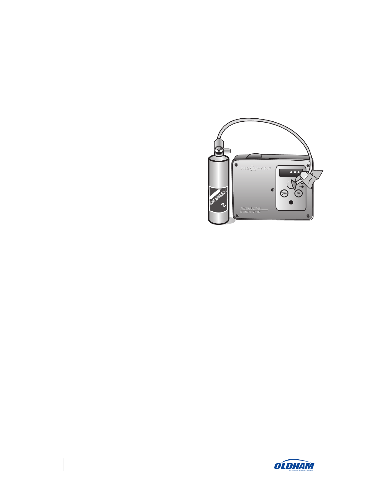
Zeroing
Zeroing an AirAware is the act of setting
the instrument to read either 000 ppm or
00.0 ppm (20.9 for oxygen) in a
gas/hazard-free environment. The
atmosphere must be clean and free from
the target gas during the zeroing process.
If through ventilation and other measures
it is impossible to entirely remove the
target gas from your facility, bottled
“zero” gas should be applied to the
instrument.
Connect the zero gas bottle, regulator,
and tubing to the calibration adapter.
Connect adapter to sensor opening and
open regulator. Allow zero gas to flow for
a minimum of 2 minutes.
007
007
With the “zero” gas still flowing to the sensor, press and hold the
key for
a total of 10 seconds. During the first 5 seconds the normal screen is still
displayed. During the next 5 seconds, the text or numeric display flashes once
per second. If the key is still held after the full 10 seconds the word “ZERO” is
displayed.
***
A flashing decimal point on the lower right corner of the display will appear for 3 minutes after start-up,
calibration, bump, or programming. This is an indicator that the 4-20 mA signal is locked at 3 mA and that all
alarm functions are disabled. Once this flashing indicator clears, all functions will return to normal.
Release the key and the zeroing process begins. At the end of the zero process,
the word "PASS" or "FAIL" is displayed for 5 seconds along with a .25
second audible beep, after which time the unit reverts to the normal reading
screen. An oxygen sensor will always be zeroed to 20.9%, regardless of what
the span gas is set to, and no span reserve is shown for oxygen during zeroing.
If the unit displays "FAIL" try again ensuring the area is free of the target gas.
If the unit fails a second time the sensor may need to be replaced. Contact
Industrial Scientific Oldham Corporation for a replacement sensor; see page
24 for ordering information.
Page 20

20
AirAware
Calibration
Industrial Scientific recommends that a full instrument calibration be
performed using a certified concentration(s) of Industrial Scientific Oldham
branded calibration gas(es) quarterly to ensure maximum accuracy. Use of
calibration gases from manufacturers other than Industrial Scientific Oldham
may void product warranties and limit liability claims against the
manufacturer.
Calibrating the AirAware is simply applying a known concentration of gas to
the unit, and “telling” the unit to self-adjust to read that concentration. The
calibration values are pre-programmed into the instrument in order to simplify
the procedure. For details on changing this pre-programmed value, refer to
page 15.
Standard AirAware Calibration Settings
CO - 100 ppm
Cl2 - 10 ppm
HCl - 10 ppm
H2S - 25 ppm
NH3 - 25 ppm
NO - 25 ppm
NO2 - 5 ppm
O2 – 20.9%
SO2 - 5 ppm
To calibrate the instrument:
• If necessary, connect zero air gas bottle, regulator and tubing to the
calibrator adapter.
• Press and hold the
button. After 5 seconds, the display will blink five
times and "Zeroing" will appears on the display. Release the
button.
• After the unit finishes auto-zeroing, it will display either PASS or FAIL. If
the sensor passes the zeroing function, switch gas cylinder and connect the
calibration adapter to the sensor opening and start the flow of gas to the
sensor by opening the regulator. Maintain the flow of gas to the sensor
until the display indicates "PASS XXX" or "FAIL". During this time the
display will flash the SPAN RESERVE value of the sensor. Once
calibration is complete, the display will flash "PASS XXXX" or
"FAILED".
• If the unit indicates “PASS XXX,” document the XXX (span reserve)
value in your calibration records. Remove calibration gas and disassemble
regulator from cylinder.***
Page 21

AirAware
21
• If the unit indicates “FAIL,” the display will alternate between “FAIL” and
actual readings. The audible alarm will sound every 1/2 second and the 420 mA signal will reflect displayed readings.***
Check the following if the unit indicates:
• “Fail”.
• Calibration gas cylinder concentration matches the pre-programmed
calibration gas settings in the “Set-up” mode.
• Calibration gas cylinder is not empty.
***
A flashing decimal point on the lower right corner of the display will appear for 3 minutes after start-up,
calibration, bump, or programming. This is an indicator that the 4-20 mA signal is locked at 3 mA and that all
alarm functions are disabled. Once this flashing indicator clears, all functions will return to normal.
If the unit fails a second time the sensor may need to be replaced. Contact
either your local distributor of Industrial Scientific Oldham Corporation
instruments or Industrial Scientific Oldham directly.
NOTE: Use only Industrial Scientific Oldham test gas equipment.
Sensor Replacement
Occasionally, AirAware sensors will need to be replaced. Repeated failures of
zero, calibration, and bump tests can be indications that the sensor has
degraded. Replacement sensors are available from authorized Industrial
Scientific Oldham distributors. Refer to page 24, Replacement Sensors and
Accessories, for part numbers.
To replace a sensor in the AirAware:
• Remove power from the unit.
• Remove the optional vanity plate (if installed) from the face of the
instrument by releasing the locking tabs (page 9).
• Loosen the 5 Phillips head (captive) screws on the faceplate allowing it to
hinge downward (page 8).
• Unplug the used sensor and discard.
Page 22

22
AirAware
006
• Remove the shorting clip or small bias circuit board from the replacement
sensor, aligning the holes in the board with the pins on the sensor; plug the
new sensor into the instrument.
009
• Replace cover, and reapply power.
Once powered, the display will briefly show the symbol for the gas being
monitored, then a live display of the gas concentration. Each AirAware
utilizes electrochemical sensors that may require between 10 and 360 minutes
(gas dependent) or 12-16 hours for NH3 and HCl to stabilize when initially
activated. During this warm-up period, the unit may display concentrations of
gas and possibly alarm. Allow sufficient time for the instrument to stabilize
prior to proceeding.
Page 23

AirAware
23
Specifications
Size:
7.2" x 5.6" x 1.6" (18.29 cm x 14.22 cm x 4.06
cm)
Weight:
17 oz. (482 grams)
Display:
4 digit high resolution bright led
Relay Rating:
Two 5-amps 30 VDC, NO and NC
Analog Output:
4-20 mA three-wire interface
200-1000 ohms @ 24 VDC
100-500 ohms @ 12 VDC
Current Draw:
125 mA @ 24 VDC
200 mA @ 12 VDC
Digital Output:
ModBus RTU, RS485
Temperature Range of
Operation:
-4°F to 122°F (-20°C to 50°C) Sensor Dependant
Relative Humidity
Range:
15-90% for Toxics
0-99% for Oxygen
Measuring Range:
HCl - 0.2 to 30.0 ppm in 0.1 ppm increments
Cl2, NO2, SO2 - 0.2 to 99.9 in 0.1 ppm
increments
NH3 - 4 to 200 ppm in 1 ppm increments
CO, H2S, NO - 0 to 999 ppm in 1 ppm increments
O2 - 0.0 to 30.0% by volume in 0.1% increments
Power:
12 - 24 VDC (120 VAC to 24 VDC, optional item)
Audio Alarm:
85 db at 1 meter
Certification Data:
CSA - C.22.2 No. 205-M 1983 (non-hazardous
locations)
Subject to change without notice.
Page 24

24
AirAware
Replacement Parts & Accessories
Industrial Scientific Oldham offers a wide selection of options necessary for
optimum AirAware performance. Supplies available for the AirAware include
external audible and visual alarms, calibration kits, vanity plates, controllers
and many more. Call for available options for your specific configuration.
Replacement Parts and Accessories
Part No.
Description
67001198
Vanity plate (option)
67000596
Calibration adapter (adapter only)
67000604
Calibration adapter assembly (includes cal adapter, tubing and
reducer)
17106659
Replacement sensor gasket
77021897
Replacement water barrier for sensor opening
67000265
120 VAC to 24 VDC power adapter (North American wall
plug)
17099391
Nylon strain relief for AC power adapter
67001123
Replacement Faceplate Screw
67001115
Replacement Faceplate/Keypad
67001131
Replacement Faceplate Hinge Strap
77024354
Replacement RFI screen
77022051
Replacement sensor seal
Replacement Sensors
Part No.
Description
17071093
Ammonia Sensor (NH3)
17051638
Carbon Monoxide Sensor (CO)
17077330
Chlorine Sensor (Cl2)
17066374
Hydrogen Chloride Sensor (HCl)
17033960
Hydrogen Sulfide Sensor (H2S)
Page 25

AirAware
25
17071242
Nitric Oxide Sensor (NO)
17060591
Nitrogen Dioxide Sensor (NO2)
17050129
Oxygen Sensor (O2)
17060575
Sulfur Dioxide Sensor (SO2)
Calibration Kits & Replacement Cylinders
Industrial Scientific Oldham offers a wide selection of calibration kits and
regulators necessary for optimum AirAware performance. Call for available
options for your specific configuration.
Calibration Kits
Part No.
Description
18102147
Ammonia Cal Kit (25 PPM 58 liter)
18100743
Carbon Monoxide Cal Kit (100 PPM 34 liter)
18101741
Chlorine Cal Kit (10 PPM 58 liter)
18102148
Hydrogen Chloride Cal Kit (10 PPM 58 liter)
18100842
Hydrogen Sulfide Cal Kit (25 PPM 58 liter)
18102238
Nitrogen Dioxide Cal Kit (5 PPM 58 liter)
68100221
Oxygen / Zero Air Cal Kit (20.9% O2 34 liter)
18102239
Sulfur Dioxide Cal Kit (5 PPM 58 liter)
18102150
Nitric Oxide Cal Kit (25 PPM, 58 liter)
Replacement Cylinders for Calibration Kits
Part No.
Description
18102151
Ammonia Replacement CYL (25 PPM 58 liter)
18100701
Carbon Monoxide Replacement CYL (100 PPM 34 liter)
18101758
Chlorine Replacement CYL (10 PPM 58 liter)
18102154
Hydrogen Chloride Replacement CYL (10 PPM 58 liter)
18100859
Hydrogen Sulfide Replacement CYL (25 PPM 58 liter)
Page 26

26
AirAware
18102219
Nitrogen Dioxide Replacement CYL (5 PPM 58 liter)
18102222
Sulfur Dioxide Replacement CYL (5 PPM 58 liter)
18100693
Oxygen / Zero Air Replacement CYL (20.9% O2 34 liter)
18102153
Nitric Oxide Replacement CYL (25 PPM 58 liter)
Calibration kits include gas cylinder, 0.5 LPM regulator and carry case.
Note: Calibration cup not included.
Urethane tubing required for SO2, Cl2, NO2, NH3, HCl and HCN gases
Warranty
Industrial Scientific Oldham portable gas monitoring instruments are
warranted to be free from defects in material and workmanship for one year
from the date of purchase, except where otherwise stated in writing in
Industrial Scientific Oldham literature accompanying the product. The above
warranty does not include sensors, battery packs, internal pumps or filters, all
of which are warranted to be free from defects in material and workmanship
for eighteen months from the date of shipment, or one year from the date of
first use, whichever occurs first, except where otherwise stated in writing in
Industrial Scientific Oldham literature accompanying the product.
All other Industrial Scientific Oldham products are warranted to be free from
defects in material and workmanship for a period of eighteen (18) months
from the date of shipment, or one (1) year from the date of first use, whichever
occurs first, except where otherwise stated in writing in Industrial Scientific
Oldham literature accompanying the product.
LIMITATION OF LIABILITY
INDUSTRIAL SCIENTIFIC OLDHAM MAKES NO OTHER
WARRANTIES, EITHER EXPRESSED OR IMPLIED, INCLUDING BUT
NOT LIMITED TO THE WARRANTIES OF MERCHANTABILITY OR
FITNESS FOR PARTICULAR PURPOSE. SHOULD THE PRODUCT FAIL
TO CONFORM TO THE ABOVE WARRANTY, BUYER’S ONLY
REMEDY AND INDUSTRIAL SCIENTIFIC OLDHAM’S ONLY
OBLIGATION SHALL BE, AT INDUSTRIAL SCIENTIFIC OLDHAM’S
SOLE OPTION, REPLACEMENT OR REPAIR OF SUCH
NONCONFORMING GOODS OR REFUND OF THE ORIGINAL
PURCHASE PRICE OF THE NONCONFORMING GOODS.
Page 27

AirAware
27
IN NO EVENT WILL INDUSTRIAL SCIENTIFIC OLDHAM BE LIABLE
FOR ANY OTHER SPECIAL, INCIDENTAL OR CONSEQUENTIAL
DAMAGES, INCLUDING LOSS OF PROFIT OR LOSS OF USE, ARISING
OUT OF THE SALE, MANUFACTURE OR USE OF ANY PRODUCTS
SOLD HEREUNDER WHETHER SUCH CLAIM IS PLEADED IN
CONTRACT OR IN TORT, INCLUDING STRICT LIABILITY IN TORT.
It shall be an express condition to Industrial Scientific Oldham’s warranty that
all products be carefully inspected for damage by Buyer upon receipt, be
properly calibrated for Buyer’s particular use, and be used, repaired, and
maintained in strict accordance with the instructions set forth in Industrial
Scientific Oldham’s product literature. Repair or maintenance by nonqualified
personnel will invalidate the warranty, as will the use of non-approved
consumables or spare parts. As with any other sophisticated product, it is
essential and a condition of Industrial Scientific Oldham’s warranty that all
personnel using the products be fully acquainted with their use, capabilities
and limitations as set forth in the applicable product literature.
Buyer acknowledges that it alone has determined the intended purpose and
suitability of the goods purchased. It is expressly agreed by the parties that any
technical or other advice given by Industrial Scientific Oldham with respect to
the use of the goods or services is given without charge and at Buyer’s risk;
therefore, Industrial Scientific Oldham assumes no obligations or liability for
the advice given or results obtained.
Page 28

28
AirAware
 Loading...