

Page 1

PH640
Software Setup Guide
59322401 Rev 1.0 my.okidata.com
Page 2

Contents
1. Installing/Uninstalling ....................................................................................................... 1
1.1 Installing (on Windows 2000 / XP) .......................................................................................................1
1.1.2 Adding Printer Drivers .............................................................................................................................. 4
1.2 Installing (on Windows Vista / 7) ..........................................................................................................6
1.2.1 Adding Printer Drivers ............................................................................................................................... 9
1.3 Uninstalling ............................................................................................................................................12
1.3.1 Windows 2000/XP ..................................................................................................................................... 12
1.3.2 Windows Vista / 7 ...................................................................................................................................... 13
2. Features ............................................................................................................................... 15
2.1 PH640 Windows Drivers ......................................................................................................................15
2.2 OKIPOS PH640 Conguration Utility .................................................................................................16
2.3 Virtual Port Emulator ...........................................................................................................................16
2.4 Printer-Status Setting Tool ..................................................................................................................16
3. Windows 2000/XP/Vista/7 Printer Driver Settings ...................................................... 17
3.1 Printer-Status Setting Tool ..................................................................................................................18
3.2 Setting the Printer ................................................................................................................................20
3.2.1 Print Mode .................................................................................................................................................. 21
3.2.2 Setting the Paper Type ............................................................................................................................. 22
3.2.3 Enabling/Disabling Black Mark Detection ........................................................................................... 23
3.2.4 Page Cut Type ............................................................................................................................................ 24
3.2.5 Document Cut Type .................................................................................................................................. 25
3.2.6 Print Speed ................................................................................................................................................. 26
3.2.7 Print Density .............................................................................................................................................. 27
3.2.8 Reverse Printing ........................................................................................................................................ 28
3.2.9 Selecting the Print Method ....................................................................................................................29
3.2.10 Document Top Logo ................................................................................................................................. 30
3.2.11 Page Top Logo ........................................................................................................................................... 31
3.2.12 Page Bottom Logo .................................................................................................................................... 32
3.2.13 Document Bottom Logo .......................................................................................................................... 33
3.2.14 Peripheral Unit Type ................................................................................................................................. 34
3.2.15 Peripheral Unit 1 ....................................................................................................................................... 35
3.2.16 Peripheral Unit 2 ....................................................................................................................................... 36
3.2.17 Pulse Width for Cash Drawer 1 ............................................................................................................... 37
3.2.18 Buzzer 1 On Time ....................................................................................................................................... 38
3.2.19 Buzzer 1 O Time ......................................................................................................................................39
3.2.20 Buzzer 1: Number of Times Buzzer Sounds .......................................................................................... 40
3.2.21 Buzzer 2 On Time ....................................................................................................................................... 41
3.2.22 Buzzer 2 O Time ......................................................................................................................................42
3.2.23 Buzzer 2: Number of Times Buzzer Sounds .......................................................................................... 43
3.3 Setting the Print Quality ......................................................................................................................44
3.4 Setting the Paper Size ..........................................................................................................................46
Page 3

3.4.1 Standard Sizes ...........................................................................................................................................46
3.4.2 User-Dened Paper Settings ...................................................................................................................48
3.5 Selecting the Print Color ......................................................................................................................50
4. Device Fonts ....................................................................................................................... 51
4.1 Device Fonts List ...................................................................................................................................51
4.2 Barcode Fonts ........................................................................................................................................53
4.2.1 Barcode Font List ....................................................................................................................................... 53
4.2.2 Entering the Barcode Font ......................................................................................................................54
4.2.3 Barcode Font Parameter List ................................................................................................................... 55
4.2.4 Generating a Barcode Using Microsoft Word ......................................................................................56
4.3 Two-dimensional Code Font ...............................................................................................................58
4.3.1 Two-dimensional Code Font List ............................................................................................................ 58
4.3.2 Entering two-dimensional Code Font ................................................................................................... 59
4.3.3 Two-dimensional Code Command Setting Font ................................................................................. 60
4.3.4 Using the Two-dimensional Code Font ................................................................................................. 65
4.4 Control Fonts .........................................................................................................................................69
4.4.1 Control Font Characters and Their Operations....................................................................................69
4.4.2 Using the Control Font with Microsoft Word ....................................................................................... 71
4.5 Restrictions and Precautions ..............................................................................................................73
5. OKIPOS PH640 Conguration Utility ............................................................................ 74
5.1 Printer Settings......................................................................................................................................78
5.1.1 Memory SW Settings ................................................................................................................................ 80
5.1.2 NVLogo ....................................................................................................................................................... 82
5.1.3 Printer Tests ................................................................................................................................................ 85
5.1.4 Ethernet I/F Setup ..................................................................................................................................... 87
5.2 Application Settings .............................................................................................................................93
5.2.1 Virtual Port Emulator ................................................................................................................................ 94
5.3 Common Data ........................................................................................................................................97
5.3.1 Image List ................................................................................................................................................... 98
6. Guidelines for Printing Documents .............................................................................103
6.1 Notes for Printing via a Serial Interface ......................................................................................... 103
6.2 Notes for Using Microsoft Word ...................................................................................................... 104
7. Guidelines for Usage in an Ethernet Environment ...................................................106
7.1. Manually Setting a Temporary IP Address .................................................................................... 106
7.2. Manually Setting an IP Address ...................................................................................................... 107
7.3. Setting up a TCP/IP Printer Port ...................................................................................................... 110
7.3.1 Adding a TCP/IP Printer Port ................................................................................................................. 110
7.3.2 Changing a TCP/IP Printer Port .............................................................................................................113
8. Revision History ...............................................................................................................115
Appendix 1. 2-dimensional Codes PDF417 Command Details ............................... App.1-1
Appendix 2. 2-dimensional Codes QR Code Command Details ............................. App.2-1
Page 4

OKIPOS
PH640
1. Installing/Uninstalling
Before using the PH640 with Windows 2000, XP, Vista, or 7, you must rst install the printer drivers.
Important: Administrator privilege is required to run the installation.
The installation procedure depends on the system that you are using.
"1.1 Installing (on Windows 2000 / XP)"
“1.2 Installing (on Windows Vista / 7)”
1.1 Installing (on Windows 2000 / XP)
To install the driver, proceed as follows.
Software Manual
Important: When using a USB interface, turn on the printer’s power after performing steps 1
to 8.
1 For Windows XP click on “OKIPOS PH640.msi” setup le. For Windows 2000 select the appropriate
“OKIPOS PH640.msi” setup les depending on the Service Pack.
under Windows 2000 SP2 OKIPOS_PH640_V100\Installer_msi\under2ksp2\OKIPOS PH640.msi
upper Windows 2000 SP3 OKIPOS_PH640_V100\Installer_msi\upper2ksp3\OKIPOS PH640.msi
2 The following window appears, and the wizard prepares to start the installation.
The time required for installation may be longer than usual depending on the environment used.
3 Click the Next button to proceed.
OKI DATA CORPORATION
- 1 -
Page 5

OKIPOS
PH640
4 Type your user information.
5 Select the type of setup.
Software Manual
After typing your user name and the name of your organization and selecting whether the installed
program is to be available to all users of this computer or only to you, click the Next button.
Select Complete to install all of the program’s features, and then click the Next button.
For Windows versions prior to Windows 2000 SP2, only the driver functions will be installed.
6 Click the Install button to begin the installation.
The program’s features are installed.
OKI DATA CORPORATION
- 2 -
Page 6

OKIPOS
PH640
7 The wizard has completed installation of the program.
Software Manual
Click the Finish button to close the wizard.
8 Next, install the printer drivers in accordance with the procedure in “1.1.2 Adding Printer Drivers”.
OKI DATA CORPORATION
- 3 -
Page 7

OKIPOS
PH640
1.1.2 Adding Printer Drivers
Follow the procedure below to add the desired printer drivers.
1 At the Windows Start menu, select Programs — Okidata — OKIPOS PH640 — Utility — OKIPOS
PH640 Printer Driver Installer.
2 When the following dialog appears, select the interface you are going to use. If you select Parallel or
Serial, proceed to click Next.
Software Manual
If you select a USB interface or the Ethernet interface, carry out the instructions shown on the screen.
When you have nished, click Next.
USB Interface
Connect the printer to the computer with a USB cable, and turn the printer’s power ON.
The computer’s Plug and Play feature will automatically detect the new hardware and install the receipt printer driver. When installation is completed successfully, the following indication will appear
in the task bar (at the bottom right of the screen).
Ethernet Interface
1) If you have not yet set an IP address for the printer you are connecting, please do so now as explained
in Section 5.1.4, “Ethernet I/F Setup”. When you click Set IP Address, the OKIPOS PH640 Conguration Utility’s Ethernet I/F Setup dialog will appear.
2) If you have not yet created a TCP/IP port for the printer you are connecting, please add the standard
Windows TCP/IP port. Click Add Port to start the Add Standard TCP/IP Printer Port wizard.
OKI DATA CORPORATION
- 4 -
Page 8

OKIPOS
PH640
3 The following window appears.
Software Manual
Enter the appropriate settings, and click Install.
1. Select a port
The port list shows the available ports. Select the port you wish to use.
2. Select the printer driver
Place a check next to the printer driver(s) you wish to install.
If you are connecting through a USB interface, the receipt driver was already installed by Plug and
Play at Step 2 above.
3. Input the printer queue name
Enter the printer queue name(s) to be used by Windows. Please do not duplicate existing queue
names. If you wish to use any of these printers as your default printer, place a check in the corresponding Default Printer checkbox.
4 When installation is completed, the following window appears.
5 At the Windows Start menu, select Printers and Faxes .
If all of the printer drivers you installed are now listed, installation has completed successfully.
OKI DATA CORPORATION
- 5 -
Page 9

OKIPOS
PH640
1.2 Installing (on Windows Vista / 7)
To install the driver, proceed as follows.
Important : When using a USB interface, turn on the printer’s power after performing steps 1 to 9 .
1 Fom the Windows Startmenu, select Programs - Accessories , right-click Command Prompt, and
then Run as administrator.
2 In the User Account Control dialog box, click the Continue or Yes button.
3 At the command prompt, perform the “OKIPOS PH640.msi” depends on dierent editions bellow.
Windows Vista/7 32-Bit Edition OKIPOS_PH640_V100\Installer_msi\upper2ksp3\OKIPOS PH640.msi
Windows Vista/7 64-Bit Edition OKIPOS_PH640_V100\Installer_msi\Vista_7_x64\OKIPOS PH640.msi
Software Manual
The following window appears, and the wizard prepares to start the installation.
The time required for installation may be longer than usual depending on the environment used.
4 Click the Next button to proceed.
OKI DATA CORPORATION
- 6 -
Page 10

OKIPOS
PH640
5 Type your user information.
Software Manual
After typing your user name and the name of your organization and selecting whether the installed
program is to be available to all users of this computer or only to you, click the Next button.
6 Select the type of setup.
Select Complete to install all of the program’s features, and then click the Next button.
7 Click the Install button to begin the installation.
OKI DATA CORPORATION
- 7 -
Page 11

OKIPOS
PH640
8 In the software installation conrmation dialog box, click Install this driver software anyway to
9 The wizard has completed installation of the program.
Software Manual
continue with installation.
Click the Finish button to close the wizard.
0 Next, install the printer drivers in accordance with the procedure in “1.2.1 Adding Printer Drivers”.
OKI DATA CORPORATION
- 8 -
Page 12

OKIPOS
PH640
1.2.1 Adding Printer Drivers
Follow the procedure below to add the desired printer drivers.
1 At the Windows Start menu, select Programs — Okidata — OKIPOS PH640 — Utility, right-click
OKIPOS PH640 Printer Driver Installer, and then select Run as administrator.
Software Manual
2 In the User Account Control dialog box, click the Allow or Yes button.
3 When the following dialog appears, select the interface you are going to use. If you select Parallel or
Serial, proceed to click Next.
If you select a USB interface or the Ethernet interface, carry out the instructions shown on the screen.
When you have nished, click Next.
OKI DATA CORPORATION
- 9 -
Page 13

OKIPOS
PH640
USB Interface
Connect the printer to the computer with a USB cable, and turn the printer’s power ON.
Ethernet Interface
Software Manual
The computer’s Plug and Play feature will automatically detect the new hardware and install the
receipt printer driver. When installation is completed successfully, the following indication will appear in the task bar (at the bottom right of the screen).
1) If you have not yet set an IP address for the printer you are connecting, please do so now as explained in “5.1.4 Ethernet I/F Setup”. If you are using 32-bit Vista or 7, when you click Set IP Ad-
dress button, the OKIPOS PH640 Conguration Utility’s Ethernet I/F Setup dialog will appear. If you
are using 64-bit Vista or 7, see “7. Guidelines for Usage in an Ethernet Environment”
2) If you have not yet created a TCP/IP port for the printer you are connecting, please add the standard
Windows TCP/IP port. Click Add Port button to start the Add Standard TCP/IP Printer Port wizard.
4 The following window appears.
Enter the appropriate settings, and click Install.
1. Select a port
The port list shows the available ports. Select the port you wish to use.
2. Select the printer driver
Place a check next to the printer driver(s) you wish to install.
If you are connecting through a USB interface, the receipt driver was already installed by Plug and
Play at Step 3 above.
3. Input the printer queue name
Enter the printer queue name(s) to be used by Windows. Please do not duplicate existing queue
names. If you wish to use any of these printers as your default printer, place a check in the corresponding Default Printer checkbox.
OKI DATA CORPORATION
- 10 -
Page 14

OKIPOS
PH640
5 When installation is completed, the following window appears.
6 On the taskbar, click Start. On Windows Vista, click Control Panel, and then click Printer to open the
Software Manual
printer folder. On Windows 7, click Devices and Printers to open the printer folder.
If all of the printer drivers you installed are now listed, installation has completed successfully.
On Windows 7, if you use USB interface to install several printer queues, there is only
one printer icon that can be displayed.
To conrm the installed printer queues, you can right click the displayed icon, OKIPOS PH640, and select “Printer Properties” or “Printing preferences…” at the dropdown list.
< On Windows 7 >
OKI DATA CORPORATION
- 11 -
Page 15

OKIPOS
PH640
Software Manual
1.3 Uninstalling
This section explains how to uninstall all PH640 printer driver software. The procedure varies according to
the OS you are using. Please refer to the subsection that corresponds to your environment.
1.3.1 Windows 2000/XP
To uninstall the driver, proceed as follows.
1 Turn o the power switch of the printer.
2 From the Windows Start menu, select Programs – Okidata – OKIPOS PH640 – Printer Uninstall.
3 When the following conrmation dialog box appears, click the Yes button to continue.
4 The uninstaller launches to remove all of the PH640 software from your computer.
OKI DATA CORPORATION
- 12 -
Page 16

OKIPOS
PH640
1.3.2 Windows Vista / 7
To uninstall the driver, proceed as follows.
1 Turn o the power switch of the printer.
2 From the Windows Start menu, select All Programs – Okidata – OKIPOS PH640, right-click Printer
Uninstall, and then select Run as administrator.
Software Manual
3 In the User Account Control dialog box, click the Continue or Yes button.
When the following conrmation dialog box appears, click the Yes button to continue.
OKI DATA CORPORATION
- 13 -
Page 17

OKIPOS
PH640
4 If the print spooler conrmation dialog box appears, select Do not close applications, and then click
Software Manual
the OK button. (Although A reboot will be required is indicated, the computer will not restart.)
5 The uninstaller launches to remove all of the PH640 software from your computer.
OKI DATA CORPORATION
- 14 -
Page 18

OKIPOS
PH640
Software Manual
2. Features
2.1 PH640 Windows Drivers
The PH640 comes with separate drivers for receipt printing, slip printing, and validation printing. These
drivers enable the printer to operate on Windows 2000, XP, Vista and 7 systems. Each driver is set up separately. On each driver, you can set basic print settings such as print mode and paper size, together with
advanced settings such as graphic logos and the operation of peripheral buzzers or cash drawers.
The following example shows settings for an optional buzzer.
Example of driver settings:
Peripheral Unit Type
Peripheral Unit 1
Peripheral Unit 2
Buzzer 1: On Time
Buzzer 1: O Time
Buzzer 1: Cycles
Buzzer
Document Bottom
No Use
500 milliseconds
2000 milliseconds
5
Document printing nishes
0.5 seconds on 0.5 seconds on 0.5 seconds on 0.5 seconds on 0.5 seconds on
2 seconds o 2 seconds o 2 seconds o 2 seconds o 2 seconds o
Document printing nishes
0.5 seconds on
0.5 seconds on
Stops
2 seconds o 2 seconds o
FEED button pressed
The total buzzer time, including on time and o time for the total number of cycles, should not exceed 30
seconds.
OKI DATA CORPORATION
- 15 -
Page 19

OKIPOS
PH640
Software Manual
2.2 OKIPOS PH640 Conguration Utility
The OKIPOS PH640 Conguration Utility provides an easy way to set the printer’s memory switches, to register graphic logos, and to make other such hard print settings.
It also oers an easy way to set up an Ethernet interface card.
Also, note that you may choose to install the utility only, without also installing the driver software.
Important: This function is supported by Windows 2000 (SP3 or later)/XP/Vista 32-bit
edition/7 32-bit edition.
2.3 Virtual Port Emulator
By using this software, printers equipped with a USB interface card or Ethernet interface card can be used
with applications that support only serial printers.
Important: Some applications do not support this feature.
This function is supported by Windows 2000 (SP3 or later)/XP/Vista 32-bit
edition/7 32-bit edition.
2.4 Printer-Status Setting Tool
You can use this software to obtain status information about the PH640 printer.
OKI DATA CORPORATION
- 16 -
Page 20

OKIPOS
PH640
Software Manual
3. Windows 2000/XP/Vista/7 Printer Driver Settings
The PH640 comes with separate printer drivers for receipt printing, slip printing, and validation printing.
These drivers enable the printer to operate on Windows 2000, XP, Vista, and 7 systems. Make settings at
each of these drivers as necessary to set up receipt, slip, and validation printing.
Note that the Receipt driver supports two print modes: Raster (the default) and Line.
If you are using a USB connection, it is recommended that you leave the mode set to Raster. If using a serial
interface, it is recommended that you set the mode to Line.
Notable dierences between these two modes are as follows.
Raster :
• Prints graphics at high speed.
• Suitable for reverse printing.
Line :
• Supports device fonts.
• Suitable for printing barcode device fonts.
The operations that can be set up from each driver are as follows.
Re ce ip t
■
Raster
Paper Type Yes Yes Yes N/A
Detect Black-Mark Position at Power-On Yes Yes N/A N/A
Page Cut Yes Yes N/A N/A
Document Cut Yes Yes N/A N/A
Print Speed Yes Yes N/A N/A
Print Density Yes Yes N/A N/A
Vertical Mount (reverse printing) Yes No Yes Yes
Document Top/Bottom Logos No Yes No No
Page Top / Bottom Logos No Yes Yes No
Peripheral Type Yes Yes Yes Yes
Buzzer / Cash-Drawer Interlock Yes Yes Yes Yes
Cash Drawer 1 Pulse Width Yes Yes Yes Yes
■
Line
Device Font No Yes Yes Yes
Control Font No Yes Yes Yes
Barcode Font No Yes No No
QR Code No Yes No No
Some functions cannot be set at the same time. If the ! mark is displayed in the Device Settings tab, refer
to Section 3.2 and after to conrm the settings.
OKI DATA CORPORATION
- 17 -
Page 21

OKIPOS
PH640
3.1 Printer-Status Setting Tool
This software allows you to set the system so that you can get printer status.
To open the setting tool’s dialog, proceed as follows.
1 On the taskbar, click Start. On Windows 2000 and XP, Click Printers and Faxes. On WIndows Vista,
click Control Panel, and then click Printers. On WIndows 7, click Devices and Printers.
2 Right-click the printer icon to display the drop-down menu. On Windows 2000 and XP, click Prop-
erties. On Windows Vista, click Run as administrator, and then click Properties. On Windows 7,
Click Printer properties(, select the Printer Queue name) .
3 If you are using Windows Vista, the User Account Control dialog appears. Click Continue.
4 At the Properties dialog, click the OKIPOS PH640 Cong tab, and click Launch Printer Status Set-
ting Tool.
Software Manual
5 If you are using Windows 7, the User Account Control dialog appears. Click Yes.
OKI DATA CORPORATION
- 18 -
Page 22

OKIPOS
PH640
Background Status
Check the Enable box to enable acquisition of status information (“cover open”, “oine”, etc.).
Note that this setting applies in common to all printer queues (Receipt, Slip, and Validation); if you change
the setting, the change applies to every queue.
Software Manual
Timeout
The timeout value sets the maximum time that the printer will wait to resume printing after paper runs out
or some other problem occurs that interrupts the data ow. If the problem is corrected within the timeout
period, the printer will resume printing from where it left o.
Important: If the problem is not corrected within the timeout period, an error message
appears and the remaining print data is deleted.
OKI DATA CORPORATION
- 19 -
Page 23

OKIPOS
PH640
3.2 Setting the Printer
Using the printer’s Properties dialog box, you can set various functions of this driver.
Begin by opening the Properties dialog box, as follows.
1 On the taskbar, click Start. On Windows 2000 and XP, Click Printers and Faxes. On WIndows Vista,
click Control Panel, and then click Printers. On WIndows 7, click Devices and Printers.
2 Right-click the printer icon to display the drop-down menu. On Windows 2000 and XP, click Prop-
erties. On Windows Vista, click Run as administrator, and then click Properties. On Windows 7,
Click Printer properties(, select the Printer Queue name) .
3 If you are using Windows Vista, the User Account Control dialog appears. Click Continue.
4 At the Properties dialog, click the Device Settings tab.
Software Manual
Available settings vary for each driver. On the Receipt driver, available settings also vary according to
whether you are using Raster mode or Line mode. In the explanations below, the following symbols appear at the top right of each page to indicate the drivers (and modes) for which the described setting is
available:
.
OKI DATA CORPORATION
- 20 -
Page 24

OKIPOS
PH640
Software Manual
3.2.1 Print Mode
Sets the print mode. For details of each mode, refer to "3. Windows 2000/XP/Vista/7 Printer Driver Settings".
Available settings are as follows.
Setting Default Meaning
Raster
Line Sets Line mode.
Setting the print mode:
Sets Raster mode.
OKI DATA CORPORATION
- 21 -
Page 25

OKIPOS
PH640
3.2.2 Setting the Paper Type
Set this to the appropriate paper type.
Available settings are as follows.
Setting Default Meaning
Receipt
Ticket
Black Mark
*1 Receipt driver only
Setting the paper type:
*1
Software Manual
Variable length: the printer does not output white-space padding
at the end of the page data.
Fixed length: the printer outputs white-space padding up to the
end of the xed-length page.
Fixed length: the printer outputs white-space padding up to the
next black mark.
If you wish to use journal-type printing (with no page breaks), set the paper type to Receipt (variablelength control), and set the page size to the receipt length (for example “72 mm × Receipt”) by appropriately setting the feed method and paper allocation (see "3.4.1 Standard Sizes").
OKI DATA CORPORATION
- 22 -
Page 26

OKIPOS
PH640
3.2.3 Enabling/Disabling Black Mark Detection
If this feature is set to Enable, the printer will detect the black mark position when turned on.
Important: This feature is disabled when the paper type is set to “Black Mark”.
Available settings are as follows.
Setting Default Meaning
Disable
Enable At power on, feeds paper according to black mark position.
Enabling or disabling black mark detection:
At power on, does not execute paper feed in accordance with detection of black mark position.
Software Manual
Important: This setting is not available if the paper type is set to “Receipt” or “Ticket”.
OKI DATA CORPORATION
- 23 -
Page 27

OKIPOS
PH640
3.2.4 Page Cut Type
Sets the cutting method for the end of each non-nal page of a document.
Available settings are as follows.
Setting Default Meaning
Software Manual
No Cut
Partial Cut
Setting the page cutting:
Printer does not feed or cut paper.
Printer feeds paper to cut position, and then cuts it leaving one
point at the center.
OKI DATA CORPORATION
- 24 -
Page 28

OKIPOS
PH640
3.2.5 Document Cut Type
Sets the cutting method for the nal page of the document.
Available settings are as follows.
Setting Default Meaning
No Cut Printer does not feed or cut paper.
Partial Cut
Setting the document cutting:
Printer feeds paper to cut position, and then cuts it leaving one
point at the center.
Software Manual
OKI DATA CORPORATION
- 25 -
Page 29

OKIPOS
PH640
3.2.6 Print Speed
Sets the print speed. Note that the setting also aects the print quality.
Available settings are as follows.
Setting Default Meaning
Software Manual
High
Middle Sets print quality and print speed to intermediate level.
Low Provides the highest print quality but lowers print speed.
Setting the print speed:
Priority is given to print speed over print quality.
Important: The Print Speed setting is ignored (and xed speed will be used) if print
quality is set to 203×406 dpi, or if printing is in color.
OKI DATA CORPORATION
- 26 -
Page 30

OKIPOS
PH640
3.2.7 Print Density
Sets the print density.
Available settings are as follows.
Setting Default Meaning
-3 to -1 Larger value with – (minus) makes print density lighter.
Software Manual
Standard
+1 to +3 Larger value with + (plus) makes print density darker.
Setting the print density:
Prints with normal density.
Important: When setting up color printing, this density setting has no eect on black
print density (which is xed).
OKI DATA CORPORATION
- 27 -
Page 31

OKIPOS
PH640
3.2.8 Reverse Printing
Set this to Enable if you wish to rotate printing 180 degrees.
Available settings are as follows.
Setting Default Meaning
Software Manual
Re ce ip t
Disable
Enable Printing is inverted, top to bottom.
Setting the reverse printing mode:
Prints normally.
Important: On the Receipt driver: the following limitations apply. (1) Reverse printing
is eective only in Raster print mode; (2) Reverse printing cannot be used
together with logo printing.
OKI DATA CORPORATION
- 28 -
Page 32
OKIPOS
PH640
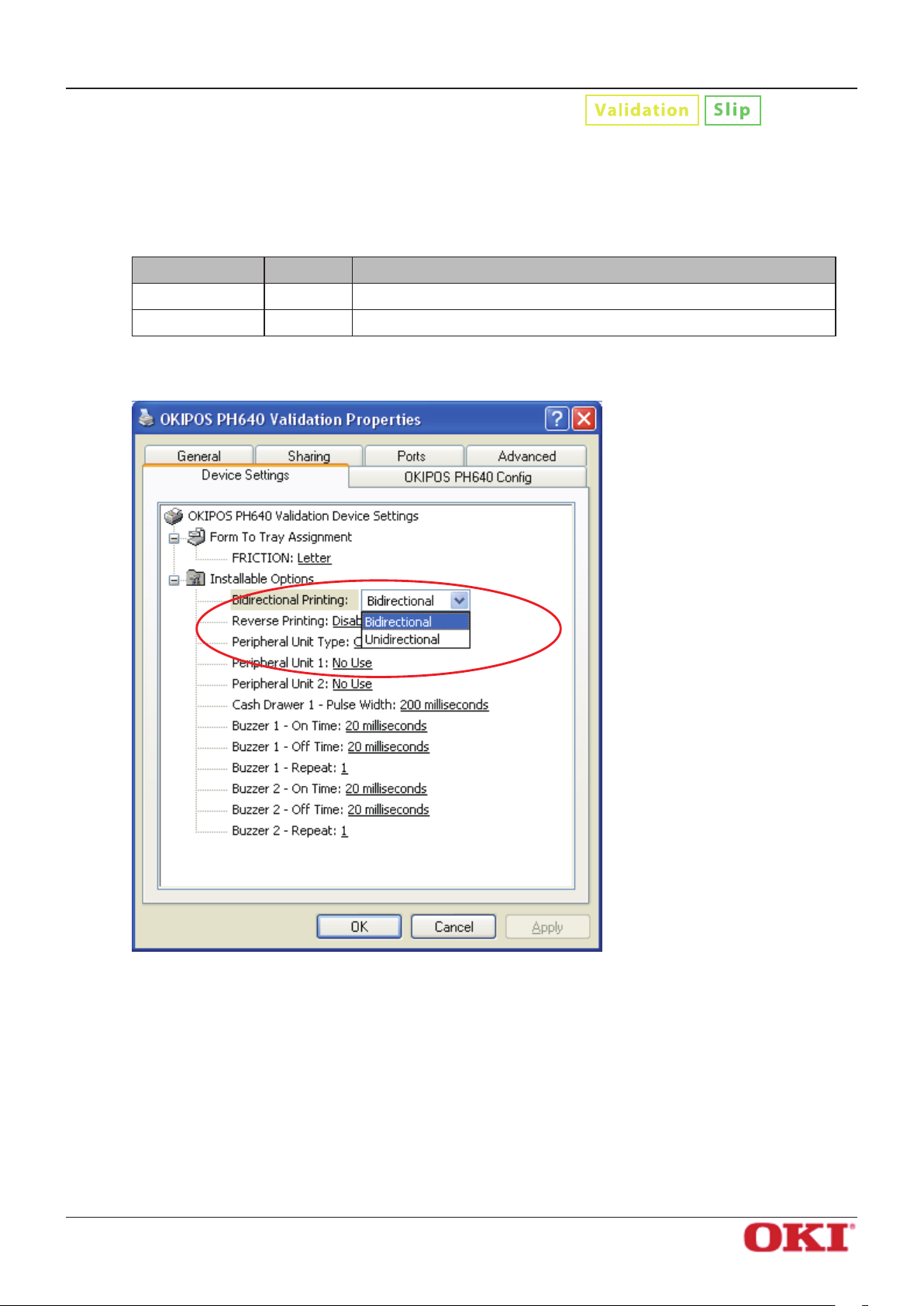
3.2.9 Selecting the Print Method
Use this feature to select either unidirectional or bidirectional printing.
Note that the setting aects both the print speed and the print quality.
Available settings are as follows.
Setting Default Meaning
Software Manual
Bidirectional
Unidirectional Printer prints in one direction only.
Setting the print method:
Printer prints in both directions.
OKI DATA CORPORATION
- 29 -
Page 33
OKIPOS
PH640
Software Manual
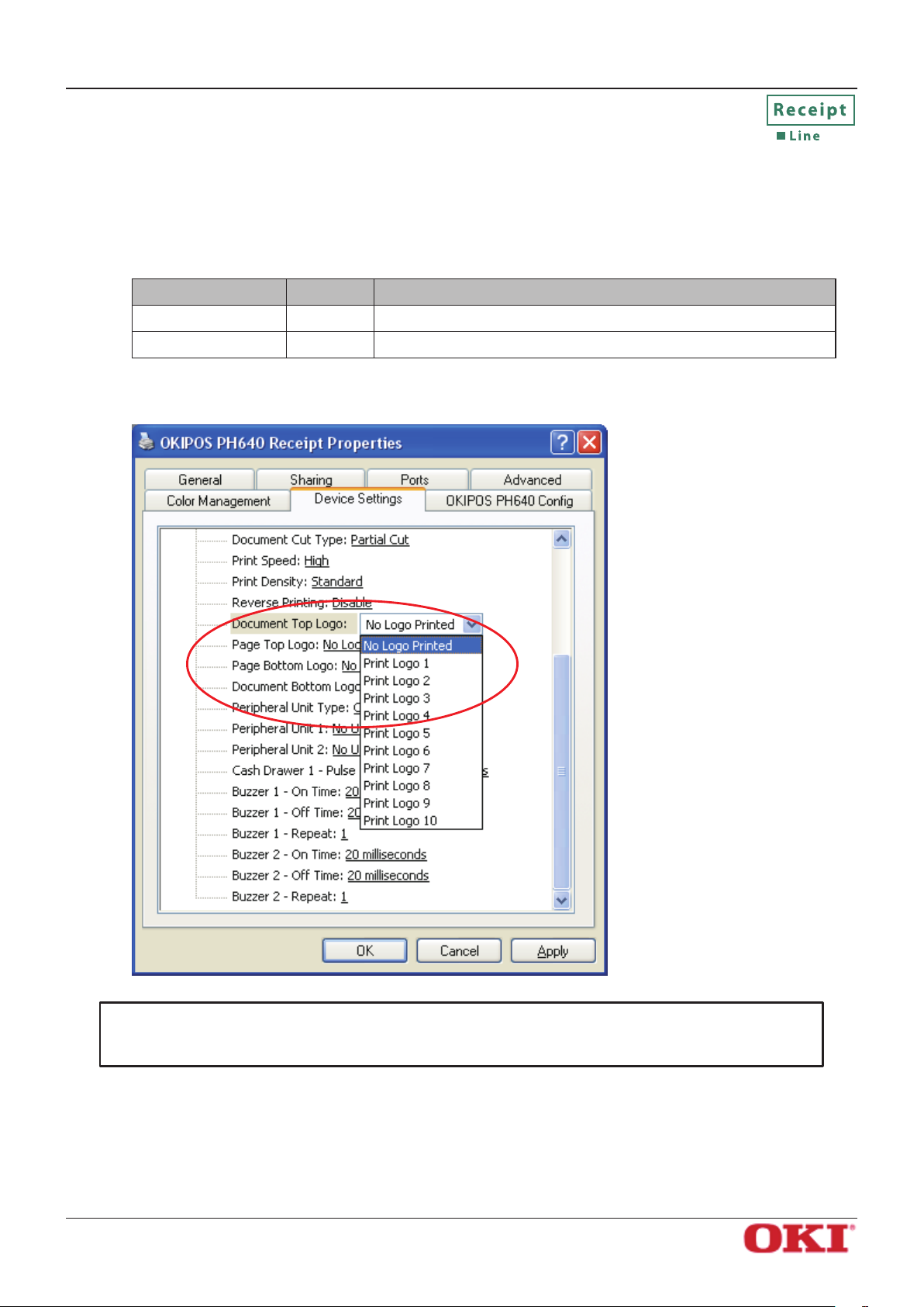
3.2.10 Document Top Logo
The NV logos are identied by their NV logo (image list) numbers. To select a top-of-document logo, choose
the appropriate logo number. Before making this setting, you must load NV logos into the printer’s nonvolatile memory.
Available settings are as follows.
Setting Default Meaning
No Logo Printed
Print Logo 1, …, 10 Prints the selected logo at the document top.
Selecting the top-of-document logo:
No logo printed at the document top.
Important: This setting is eective only in Line print mode.
Note also that logo printing cannot be used together with reverse printing.
OKI DATA CORPORATION
- 30 -
Page 34
OKIPOS
PH640
Software Manual
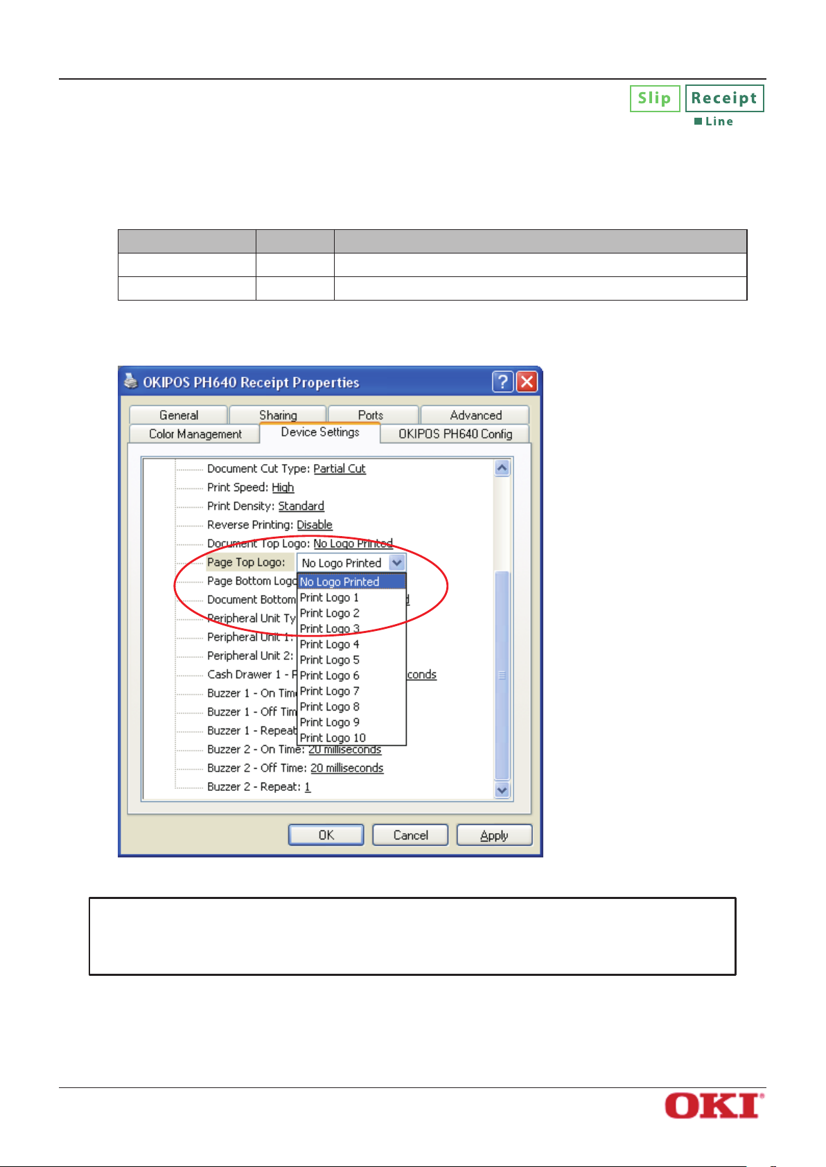
3.2.11 Page Top Logo
To select a top-of-page logo, choose the appropriate NV logo (image list) number. Before making this setting, you must load NV logos into the printer’s nonvolatile memory.
Available settings are as follows.
Setting Default Meaning
No Logo Printed
Print Logo 1, …, 10 Prints the selected logo at the page top.
Selecting the top-of-page logo:
No logo printed at the page top.
Important: On the Receipt driver: the following limitations apply. (1) This setting is ef-
fective only in Line print mode; (2) Logo printing cannot be used together
with reverse printing.
OKI DATA CORPORATION
- 31 -
Page 35
OKIPOS
PH640
Software Manual
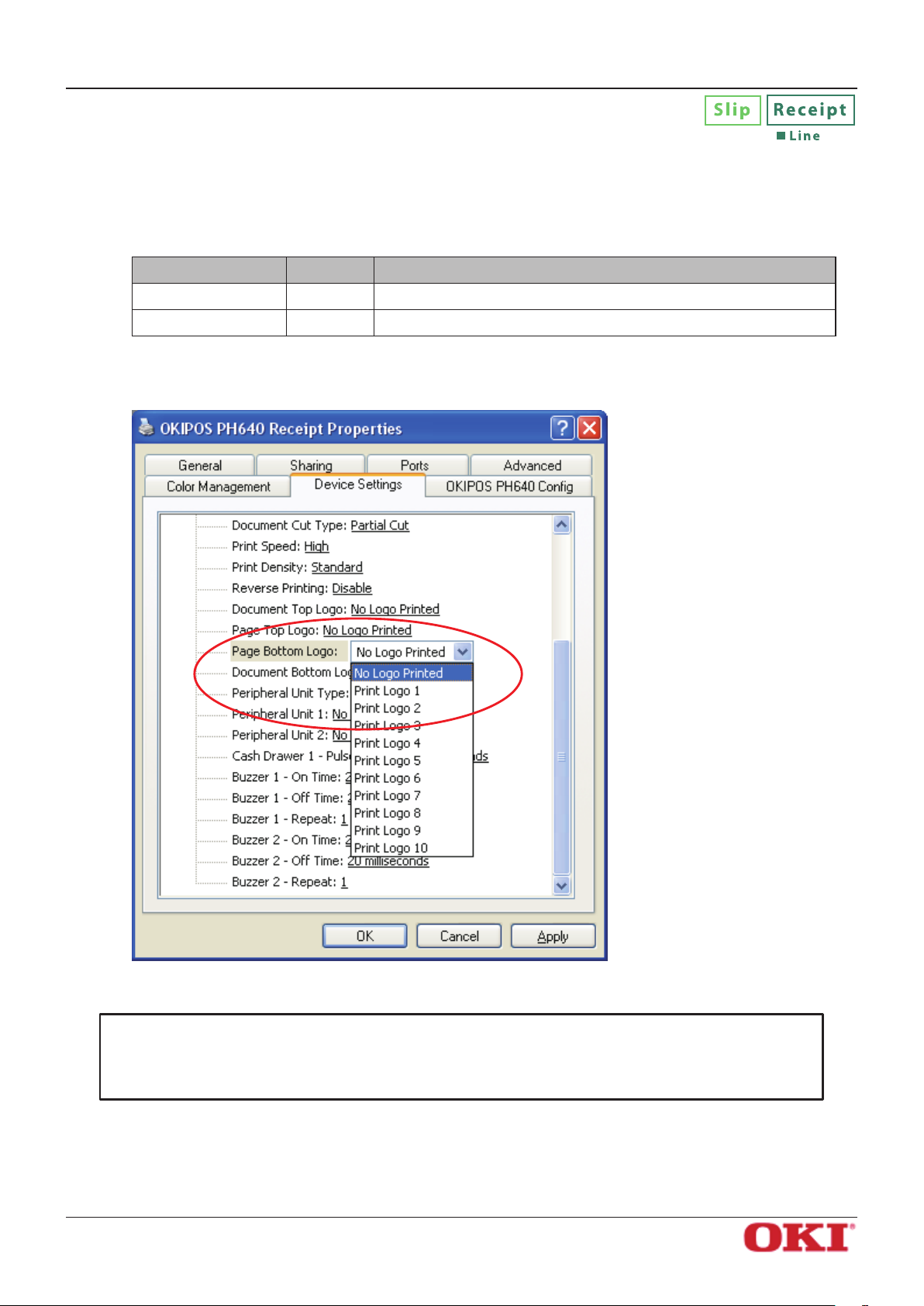
3.2.12 Page Bottom Logo
To select the bottom-of-page logo, choose the appropriate NV logo (image list) number. Before making this
setting, you must load NV logos into the printer’s nonvolatile memory.
Available settings are as follows.
Setting Default Meaning
No Logo Printed
Print Logo 1, …, 10 Prints the selected logo at the page bottom.
Selecting the bottom-of-page logo:
No logo printed at the page bottom.
Important: On the Receipt driver: the following limitations apply. (1) This setting is ef-
fective only in Line print mode; (2) Logo printing cannot be used together
with reverse printing.
OKI DATA CORPORATION
- 32 -
Page 36
OKIPOS
PH640
Software Manual
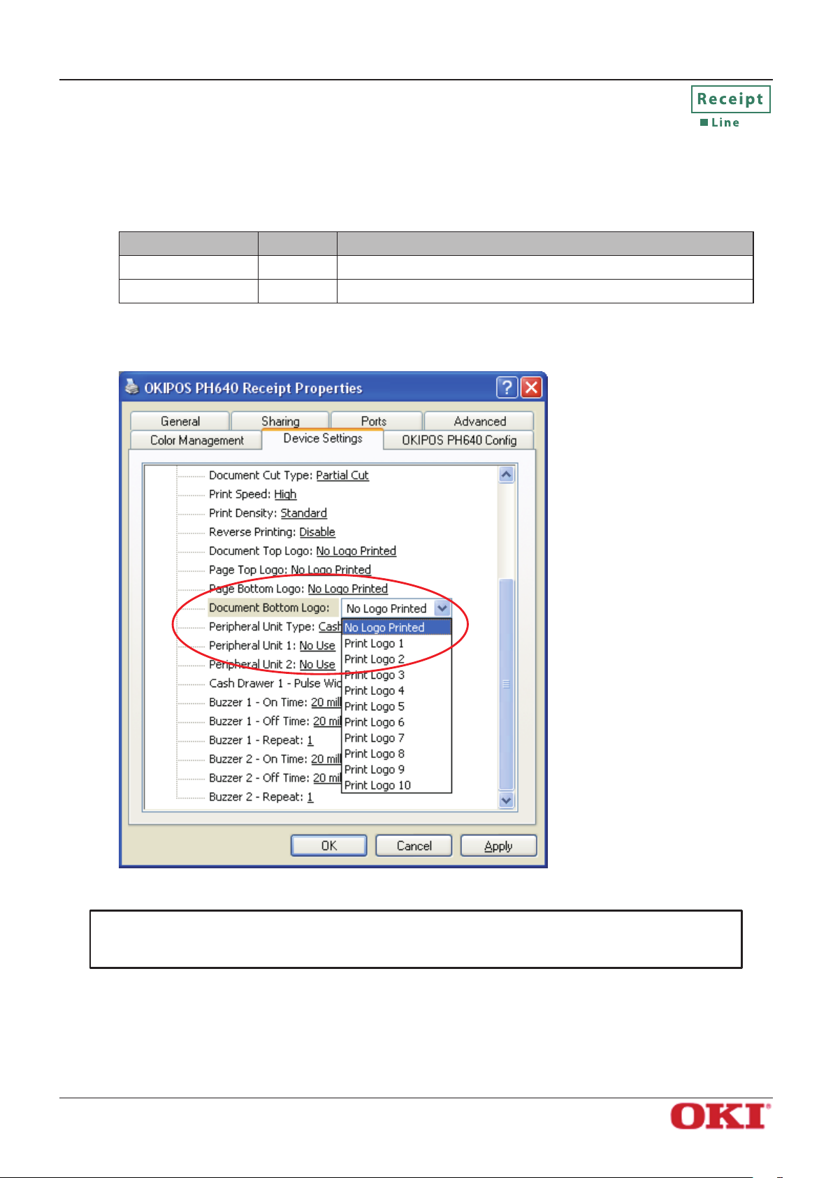
3.2.13 Document Bottom Logo
To select the bottom-of-document logo, choose the appropriate NV logo (image list) number. Before making this setting, you must load NV logos into the printer’s nonvolatile memory.
Available settings are as follows.
Setting Default Meaning
No Logo Printed
Print Logo 1, …, 10 Prints the selected logo at the document bottom.
Selecting the bottom-of-document logo:
No logo printed at the document bottom.
Important: This setting is eective only in Line print mode.
Note also that logo printing cannot be used together with reverse printing.
OKI DATA CORPORATION
- 33 -
Page 37
OKIPOS
PH640
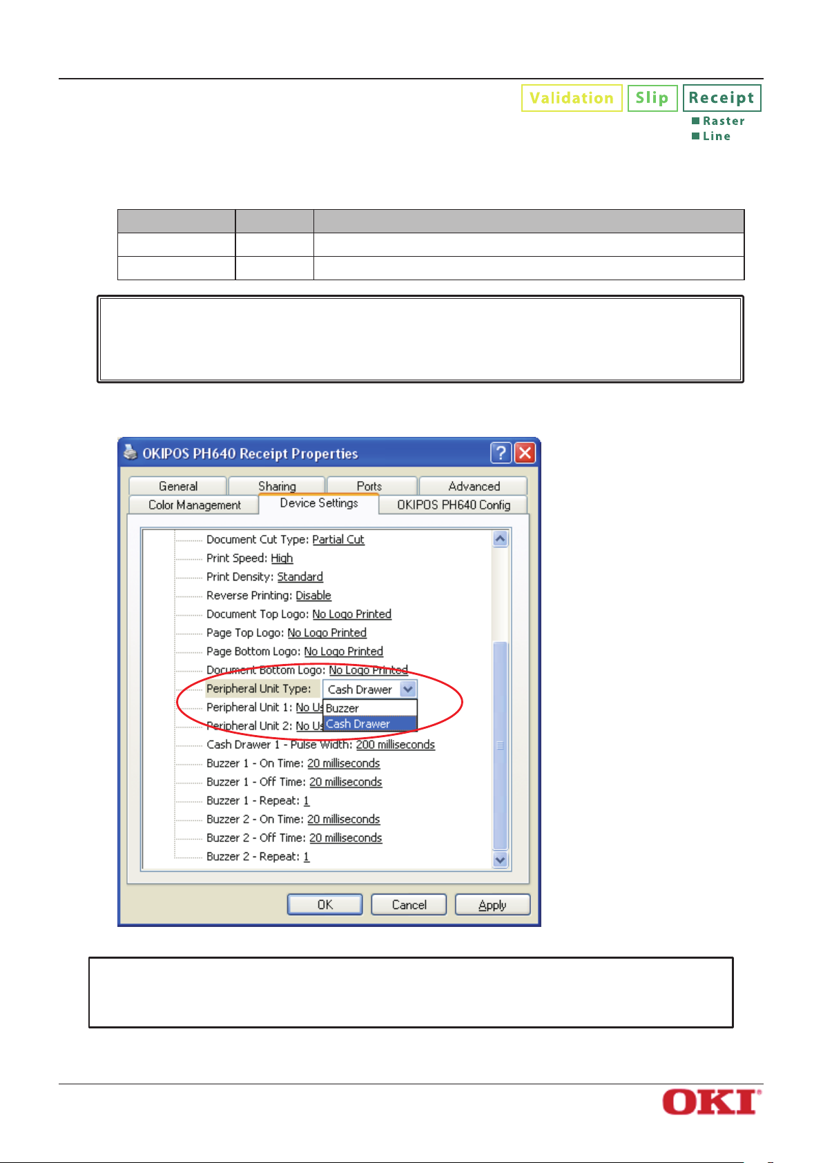
3.2.14 Peripheral Unit Type
Sets the peripheral unit type.
Available settings are as follows.
Setting Default Meaning
Buzzer Selects the buzzer as the peripheral unit.
Software Manual
Cash Drawer
Caution : If you are using a peripheral device (For example, Cash drawer, etc) other
than a buzzer, do not select “Buzzer” in the Peripheral Unit Type selection.
Otherwise, the peripheral device you are using may be destroyed.
Setting the peripheral unit type:
Selects the cash drawer as the peripheral unit.
Important: Buzzers are optional devices.
Note that it is not possible to use buzzers and cash drawers at the same
time.
OKI DATA CORPORATION
- 34 -
Page 38
OKIPOS
PH640
Software Manual
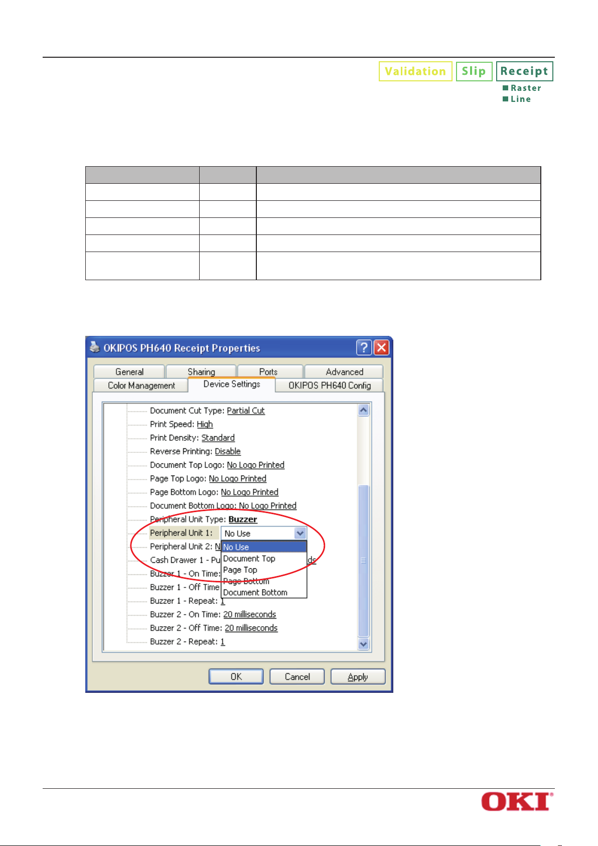
3.2.15 Peripheral Unit 1
Sets the operation timing of the peripheral unit 1 that was selected in Peripheral Unit Type. When Cash
Drawer is selected for the peripheral unit type, Page Top and Page Bottom cannot be selected.
Available settings are as follows.
Setting Default Meaning
No Use
Document Top
Page Top Operates the selected peripheral unit at the page top.
Page Bottom Operates the selected peripheral unit at the page bottom.
Document Bottom
*1 Receipt driver only
Setting the peripheral unit 1:
*1
*1
Does not use the peripheral unit.
Operates the selected peripheral unit at the document top.
Operates the selected peripheral unit at the document
bottom.
OKI DATA CORPORATION
- 35 -
Page 39
OKIPOS
PH640
Software Manual
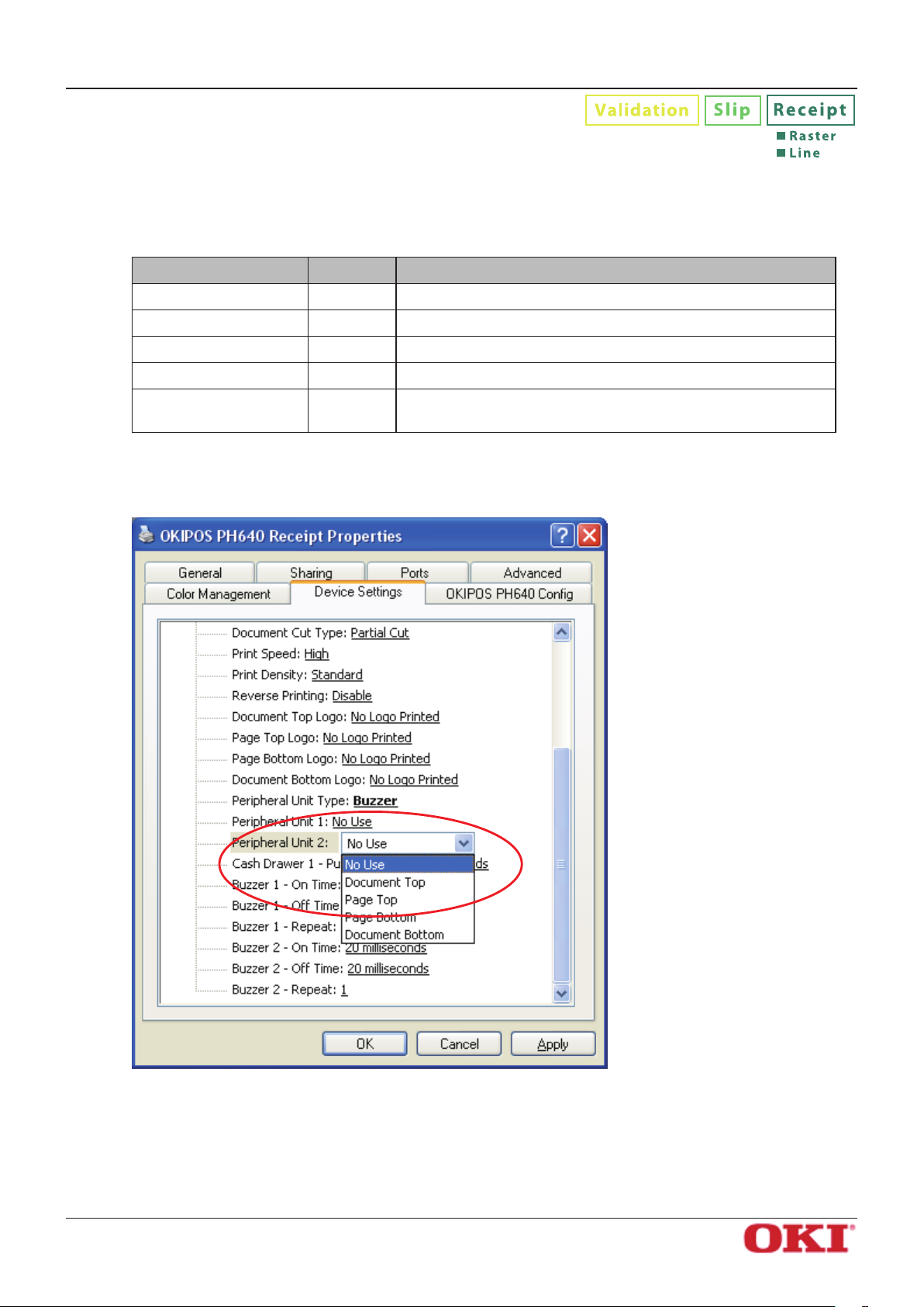
3.2.16 Peripheral Unit 2
Sets the operation timing of the peripheral unit 2 that was selected in Peripheral Unit Type.
When Cash Drawer is selected for the peripheral unit type, Page Top and Page Bottom cannot be selected.
Available settings are as follows.
Setting Default Meaning
No Use
Document Top
Page Top Operates the selected peripheral unit at the page top.
Page Bottom Operates the selected peripheral unit at the page bottom.
Document Bottom
*1 Receipt driver only
Setting the peripheral unit 2:
*1
*1
Does not use the peripheral unit.
Operates the selected peripheral unit at the document top.
Operates the selected peripheral unit at the document
bottom.
OKI DATA CORPORATION
- 36 -
Page 40
OKIPOS
PH640
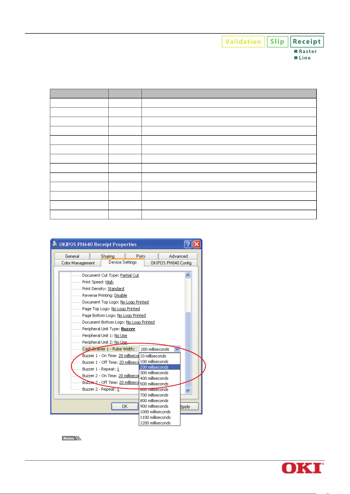
3.2.17 Pulse Width for Cash Drawer 1
Sets the pulse width for cash drawer 1 when Cash Drawer is selected for the Peripheral Unit Type.
Available settings are as follows.
Setting Default Meaning
10 milliseconds Pulse width is 0.01 second.
100 milliseconds Pulse width is 0.1 second.
200 milliseconds
300 milliseconds Pulse width is 0.3 second.
400 milliseconds Pulse width is 0.4 second.
500 milliseconds Pulse width is 0.5 second.
600 milliseconds Pulse width is 0.6 second.
700 milliseconds Pulse width is 0.7 second.
800 milliseconds Pulse width is 0.8 second.
900 milliseconds Pulse width is 0.9 second.
1000 milliseconds Pulse width is 1.0 second.
1100 milliseconds Pulse width is 1.1 seconds.
1200 milliseconds Pulse width is 1.2 seconds.
Pulse width is 0.2 second.
Software Manual
Setting cash drawer 1:
The pulse width for cash drawer 2 is xed at 200 milliseconds.
OKI DATA CORPORATION
- 37 -
Page 41

OKIPOS
PH640
Software Manual
3.2.18 Buzzer 1 On Time
Sets the buzzer 1 on time according to the timing set in Peripheral Unit 1 when Buzzer was selected in
Peripheral Unit Type. For details of the settings and examples of operation, refer to"2.1 PH640 Windows
Drivers".
Available settings are as follows.
Setting Default Meaning
20 milliseconds
40 milliseconds Set to 0.04 second.
100 milliseconds Set to 0.1 second.
200 milliseconds Set to 0.2 second.
500 milliseconds Set to 0.5 second.
1000 milliseconds Set to 1.0 second.
2000 milliseconds Set to 2.0 seconds.
5000 milliseconds Set to 5.0 seconds.
Setting the buzzer 1 on time:
Set to 0.02 second.
OKI DATA CORPORATION
- 38 -
Page 42

OKIPOS
PH640
Software Manual
3.2.19 Buzzer 1 O Time
Sets the buzzer 1 o time according to the timing set in Peripheral Unit 1 when Buzzer was selected in
Peripheral Unit Type. For details of the settings and examples of operation, refer to "2.1 PH640 Windows
Drivers".
Available settings are as follows.
Setting Default Meaning
20 milliseconds
40 milliseconds Set to 0.04 second.
100 milliseconds Set to 0.1 second.
200 milliseconds Set to 0.2 second.
500 milliseconds Set to 0.5 second.
1000 milliseconds Set to 1.0 second.
2000 milliseconds Set to 2.0 seconds.
5000 milliseconds Set to 5.0 seconds.
Setting the buzzer 1 o time:
Set to 0.02 second.
OKI DATA CORPORATION
- 39 -
Page 43

OKIPOS
PH640
Software Manual
3.2.20 Buzzer 1: Number of Times Buzzer Sounds
Sets the number of times that buzzer 1 sounds according to the timing set in Peripheral Unit 1 when
Buzzer was selected in Peripheral Unit Type. Regardless of the number of times specied for the buzzer
to sound, the buzzer stops when the FEED button is pressed. For details of the settings and examples of
operation, refer to "2.1 PH640 Windows Drivers".
Available settings are as follows.
Setting Default Meaning
1
2 Buzzer 1 sounds 2 times.
3 Buzzer 1 sounds 3 times.
5 Buzzer 1 sounds 5 times.
10 Buzzer 1 sounds 10 times.
15 Buzzer 1 sounds 15 times.
20 Buzzer 1 sounds 20 times.
Setting the number of times buzzer 1 sounds:
Buzzer 1 sounds 1 time.
OKI DATA CORPORATION
- 40 -
Page 44

OKIPOS
PH640
Software Manual
3.2.21 Buzzer 2 On Time
Sets the buzzer 2 on time according to the timing set in Peripheral Unit 2 when Buzzer was selected in
Peripheral Unit Type. For details of the settings and examples of operation, refer to "2.1 PH640 Windows
Drivers".
Available settings are as follows.
Setting Default Meaning
20 milliseconds
40 milliseconds Set to 0.04 second.
100 milliseconds Set to 0.1 second.
200 milliseconds Set to 0.2 second.
500 milliseconds Set to 0.5 second.
1000 milliseconds Set to 1.0 second.
2000 milliseconds Set to 2.0 seconds.
5000 milliseconds Set to 5.0 seconds.
Setting the buzzer 2 on time:
Set to 0.02 second.
OKI DATA CORPORATION
- 41 -
Page 45

OKIPOS
PH640
Software Manual
3.2.22 Buzzer 2 O Time
Sets the buzzer 2 o time according to the timing set in Peripheral Unit 2 when Buzzer was selected in
Peripheral Unit Type. For details of the settings and examples of operation, refer to "2.1 PH640 Windows
Drivers".
Available settings are as follows.
Setting Default Meaning
20 milliseconds
40 milliseconds Set to 0.04 second.
100 milliseconds Set to 0.1 second.
200 milliseconds Set to 0.2 second.
500 milliseconds Set to 0.5 second.
1000 milliseconds Set to 1.0 second.
2000 milliseconds Set to 2.0 seconds.
5000 milliseconds Set to 5.0 seconds.
Setting the buzzer 2 o time:
Set to 0.02 second.
OKI DATA CORPORATION
- 42 -
Page 46

OKIPOS
PH640
Software Manual
3.2.23 Buzzer 2: Number of Times Buzzer Sounds
Sets the number of times that buzzer 2 sounds according to the timing set in Peripheral Unit 2 when
Buzzer was selected in Peripheral Unit Type. Regardless of the number of times specied for the buzzer
to sound, the buzzer stops when the FEED button is pressed. For details of the settings and examples of
operation, refer to "2.1 PH640 Windows Drivers".
Available settings are as follows.
Setting Default Meaning
1
2 Buzzer 2 sounds 2 times.
3 Buzzer 2 sounds 3 times.
5 Buzzer 2 sounds 5 times.
10 Buzzer 2 sounds 10 times.
15 Buzzer 2 sounds 15 times.
20 Buzzer 2 sounds 20 times.
Setting the number of times buzzer 2 sounds:
Buzzer 2 sounds 1 time.
OKI DATA CORPORATION
- 43 -
Page 47

OKIPOS
PH640
3.3 Setting the Print Quality
To open the dialog, proceed as follows.
1. On the taskbar, click Start. On Windows 2000 and XP, click Printers and Faxes. On Windows Vista,
click Control Panel, and then click Printers. On WIndows 7, click Devices and Printers.
2. Right-click the print driver that you wish to set. In the drop-down menu, click Printing Preferences.
3. Click the Layout tab, and then click the Advanced button.
Software Manual
4. At the Advanced Options dialog, set Graphic — Print Quality to the desired setting.
Example: Setting the Print Quality for the Receipt driver
OKI DATA CORPORATION
- 44 -
Page 48
OKIPOS
PH640
Receipt Driver
The following settings are available.
Setting Default Meaning
203 × 406 dots per inch Print at 203 dpi (w) × 406 dpi (h).
Software Manual
203 × 203 dots per inch
Important: The 203×406-dpi setting is eective only in Raster print mode and only if
color printing has been disabled.
Print at 203 dpi (w) × 203 dpi (h).
Slip Driver
The following settings are available.
Setting Default Meaning
160 × 144 dots per inch
160 × 72 dots per inch Print at 160 dpi (w) × 72 dpi (h).
80 × 72 dots per inch Print at 80 dpi (w) × 72 dpi (h).
Print at 160 dpi (w) × 144 dpi (h).
Validation Driver
The following settings are available.
Setting Default Meaning
160 × 144 dots per inch
160 × 72 dots per inch Print at 160 dpi (w) × 72 dpi (h).
80 × 72 dots per inch Print at 80 dpi (w) × 72 dpi (h).
Print at 160 dpi (w) × 144 dpi (h).
OKI DATA CORPORATION
- 45 -
Page 49
OKIPOS
PH640
Software Manual
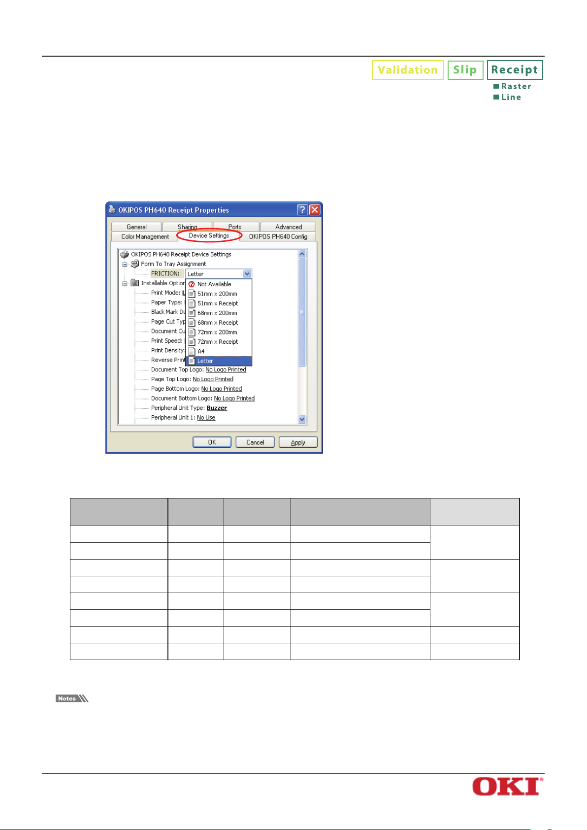
3.4 Setting the Paper Size
The PH640 drivers let you use both preset standard sizes and custom, user-dened sizes.
3.4.1 Standard Sizes
The paper size can be selected separately for each driver. To proceed, open the driver’s Properties window
and click the Device Settings tab.
Example: Setting the Paper Size for the Receipt driver
The following tables show the predened paper sizes available for each driver.
Receipt driver
Setting Default Print Width Length
51mm × 200mm 51mm 200mm
51mm × Receipt 51mm
68mm × 200mm 68mm 200mm
68mm × Receipt 68mm
72mm × 200mm 72mm 200mm
72mm × Receipt 72mm
A4 210mm 297mm -
Letter
* In general, the operating system's maximum print height is about 3m(3,000mm).
Please be sure to set a print width that is smaller than the paper width, so as to allow for margins.
If you wish, you can set the printer to produce journal-type printing (printing without page breaks) as
follows: Select the paper size that matches the receipt length, and set the paper type to Receipt (variablelength control).
8.5 inch 11 inch -
* OS's maximum print height
* OS's maximum print height
* OS's maximum print height
Recommended
Paper Width
57.5±0.5 (mm)
75.5±0.5 (mm)
79.5±0.5 (mm)
OKI DATA CORPORATION
- 46 -
Page 50
OKIPOS
PH640
Slip driver
40mm x 254mm(PH640S) 40mm 254mm
45mm x 254mm(PH640S) 45mm 254mm
50mm x 254mm(PH640S) 50mm 254mm
55mm x 254mm(PH640S) 55mm 254mm
60mm x 254mm(PH640S) 60mm 254mm
65mm x 254mm(PH640S) 65mm 254mm
70mm x 254mm(PH640S) 70mm 254mm
75mm x 254mm(PH640S) 75mm 254mm
80mm x 254mm(PH640S) 80mm 254mm
85mm x 254mm(PH640S) 85mm 254mm
A4 210mm 297mm
Software Manual
Setting Default Print Width Length
Letter
Validation driver
Setting Default Print Width Length
40mm x 33mm(PH640V) 40mm 33mm
45mm x 33mm(PH640V) 45mm 33mm
50mm x 33mm(PH640V) 50mm 33mm
55mm x 33mm(PH640V) 55mm 33mm
60mm x 33mm(PH640V) 60mm 33mm
65mm x 33mm(PH640V) 65mm 33mm
70mm x 33mm(PH640V) 70mm 33mm
75mm x 33mm(PH640V) 75mm 33mm
80mm x 33mm(PH640V) 80mm 33mm
85mm x 33mm(PH640V) 85mm 33mm
A4 210mm 297mm
Letter
8.5 inch 11 inch
8.5 inch 11 inch
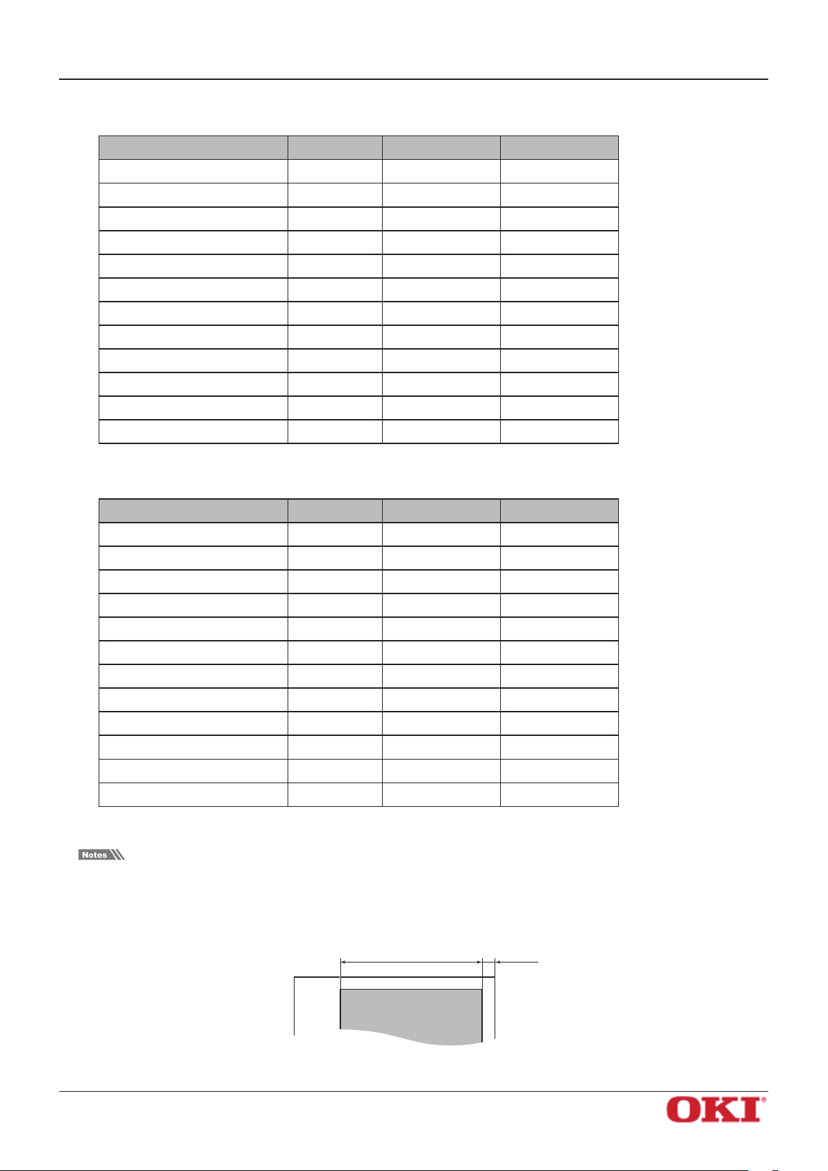
Please be sure to set a print width that is smaller than the paper width, so as to allow for margins.
Note that the Slip and Validations drivers start left-side printing at a distance of print width + right margin
(5.6 mm) from the right edge of the paper.
OKI DATA CORPORATION
Margin (5.6 mm)Print width
Print area
- 47 -
Page 51
OKIPOS
PH640
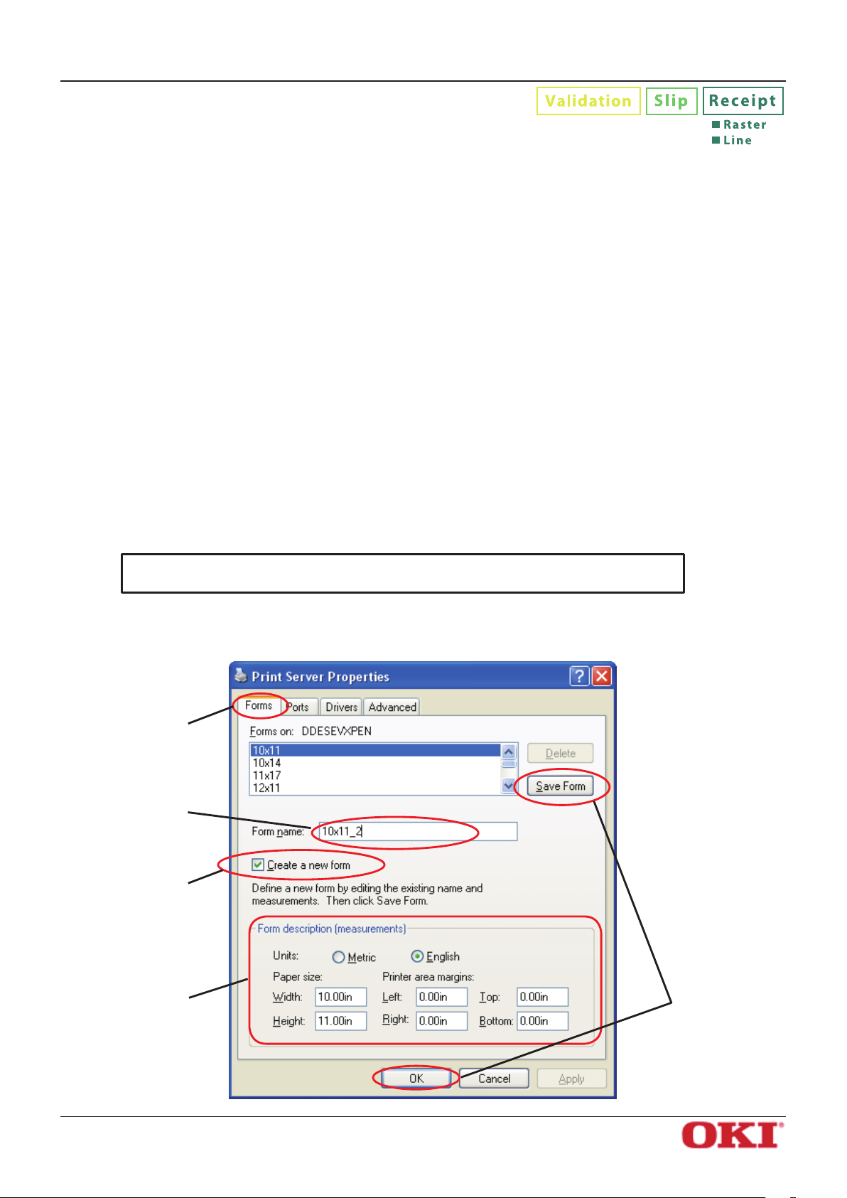
3.4.2 User-Dened Paper Settings
The paper size that will be used can be dened.
The procedure is as follows.
1 On the taskbar, click Start. On Windows 2000 and XP, click Printers and Faxes. On Windows Vista,
click Control Panel, and then click Printers. On Windows 7, click Devices and Printers.
2 On Windows 2000, XP, and Vista, right-click a blank area in the Printers folder to display the drop-
down menu. On Windows 2000 and XP, click Server Properties. On Windows Vista, click Run as
administrator, and then click Server Properties. On Windows 7, select the printer icon, and click
Printer server properties on the menu-bar.
3 If you are using Windows Vista, the User Account Control dialog appears. Click Continue.
4 Click the Forms tab.
5 If you are using Windows 7, click Change Form Settings button.
6 Select the Create a new form check box.
Software Manual
7 In the Form name textbox, overwrite the current name with a new name for the custom size you are
dening.
8 In the Form description (measurements) area, select the appropriate Units and type the desired
Width and Height settings.
Important: Set all four margins (left, right, top, and bottom) to “0”.
9 Click the Save Form button. Click the OK button to close the dialog box.
4
7
6
8
OKI DATA CORPORATION
9
- 48 -
Page 52

OKIPOS
PH640
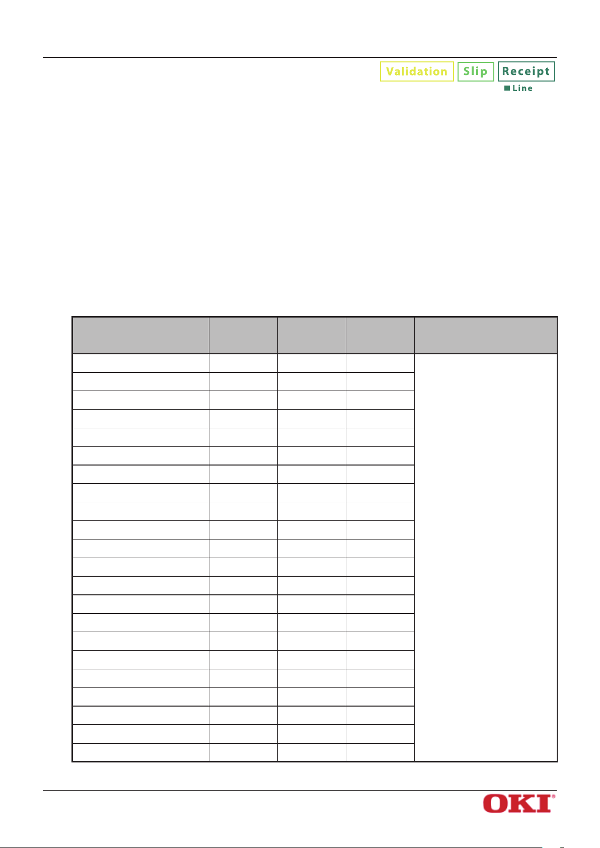
Sizes supported by each driver are as follows.
Width Height
Minimum Maximum Minimum Maximum
Receipt 25.4 mm 72 mm 25.4 mm *OS's maximum print height
Slip 25.4 mm 85 mm 75 mm *OS's maximum print height
Validation 25.4 mm 85 mm 4.3 mm 34.0 mm
* In general, the operating system's maximum print height is about 3 m (3,000 mm).
Important: User-dened sizes are available to all drivers that can support the dimen-
sions (as indicated in the table).
Software Manual
OKI DATA CORPORATION
- 49 -
Page 53

OKIPOS
PH640
3.5 Selecting the Print Color
The Receipt driver’s Raster mode supports 2-color printing.
Before you can use two-color printing, however, you must select color printing at the driver, as follows.
1 On the taskbar, click Start. On Windows 2000 and XP, click Printers and Faxes. On Windows Vista,
click Control Panel, and then click Printers. On Windows 7, click Devices and Printers.
2 Right-click the printer icon that you wish to set. In te drop-down menu, click Printing Preference
(, select the Printer Queue name).
3 Click the Paper/Quality tab.
Select the paper type appropriate for the specied print color.
Selecting the paper type and print color:
Software Manual
Re ce ip t
For normal monochrome printing (Standard thermal paper)
Media : Select normal type paper.
Color : Select check button of Black & White.
For color printing (2-color thermal paper)
Media : Select 2 color paper.
Color : Select check button of Color.
For printing on special paper (dense black printing; some special high-stability papers)
Media : Select high image stability paper.
Color : Select check button of Black & White.
OKI DATA CORPORATION
- 50 -
Page 54
OKIPOS
PH640
Software Manual
4. Device Fonts
This printer driver provides device fonts that can be used during operation in Line mode.
The printer driver supports a variety of device fonts that are installed on the printer. Printer fonts come in several
font sizes and produce clearer printing than TrueType fonts. Barcode fonts and two-dimensional code fonts can
be used to generate and print barcodes and two-dimensional codes of a variety of standards and sizes through
the use of special codes. Control fonts can be used to control the printer through the embedding of characterbased commands in print jobs.
4.1 Device Fonts List
The following table contains the device fonts that the printer driver supports. To use the device fonts,
specify the font and the appropriate font size (in points) in the application's format settings. In Microsoft
Word and Excel, the height of 24 pixels equals 8.5 points.
Receipt driver ( Line Mode )
Fonts
Printer 17cpi 12 24 48 Printer fonts ( ANK Fonts )
Printer 8.5cpi 24 24 24
Printer 17cpi Tall 12 48 48
Printer 8.5cpi Tall 24 48 24
Printer 16cpi 13 24 44
Printer 8cpi 26 24 22
Printer 16cpi Tall 13 48 44
Printer 8cpi Tall 26 48 22
Printer 14cpi 15 24 38
Printer 7cpi 30 24 19
Printer 14cpi Tall 15 48 38
Printer 7cpi Tall 30 48 19
Printer 17cpi (RED) 12 24 48
Printer 8.5cpi (RED) 24 24 24
Width
(pixels)
Height
(pixels)
Columns at
72 mm
(576 dots)
Meaning
Printer 17cpi Tall (RED) 12 48 48
Printer 8.5cpi Tall (RED) 24 48 24
Printer 16cpi (RED) 13 24 44
Printer 8cpi (RED) 26 24 22
Printer 16cpi Tall (RED) 13 48 44
Printer 8cpi Tall (RED) 26 48 22
Printer 14cpi (RED) 15 24 38
Printer 7cpi (RED) 30 24 19
OKI DATA CORPORATION
- 51 -
Page 55
OKIPOS
PH640
Software Manual
Fonts
Printer 14cpi Tall (RED) 15 48 38 Printer fonts ( ANK Fonts )
Printer 7cpi Tall (RED) 30 48 19
UPC-E 12 24 48 Barcode fonts
UPC-A 12 24 48
JAN/EAN-8 12 24 48
JAN/EAN-13 12 24 48
CODE39 12 24 48
ITF 12 24 48
NW-7(Codaber) 12 24 48
QR-CNTL 1 24 576
PDF417 1 24 576
DATA1 1 24 576
DATA2 1 24 576
DATA3 1 24 576
Width
(pixels)
Height
(pixels)
Columns at
72 mm
(576 dots)
Meaning
two-dimensional code
fonts
Control 12 24 48 Control fonts
ESC_FONT 1 24 576
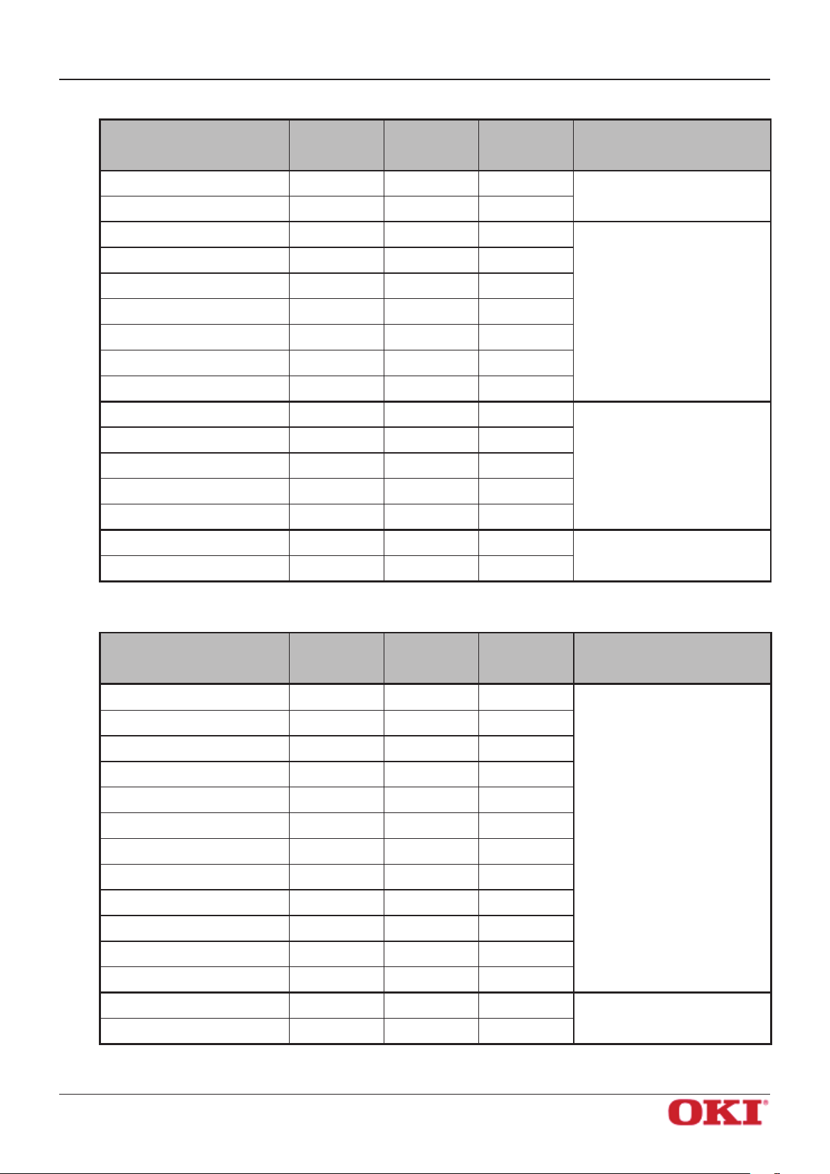
Slip and Validation drivers
Fonts
Printer 17cpi 4.5 9 60 Printer fonts ( ANK Fonts )
Printer 8.5cpi 9 9 30
Printer 17cpi Tall 4.5 18 60
Printer 8.5cpi Tall 9 18 30
Printer 14cpi 6 9 45
Printer 7cpi 12 9 22
Printer 14cpi Tall 6 18 45
Printer 7cpi Tall 12 18 22
Printer 9cpi 9 9 30
Printer 4.5cpi 18 9 15
Width
(pixels)
Height
(pixels)
Columns at
85 mm
(540 dots)
Meaning
Printer 9cpi Tall 9 18 30
Printer 4.5cpi Tall 18 18 15
Control - - -
ESC_FONT - - -
OKI DATA CORPORATION
Control fonts
- 52 -
Page 56
OKIPOS
PH640
4.2 Barcode Fonts
This printer driver's barcode fonts are available for use during operation in Line mode.
Select barcode fonts and enter the code to generate and print the barcode.
When printing a barcode image is printed, and then notations are printed under the barcode image.
Barcode images do not appear in the window of the application.
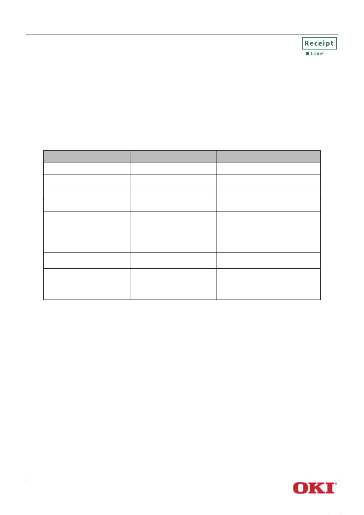
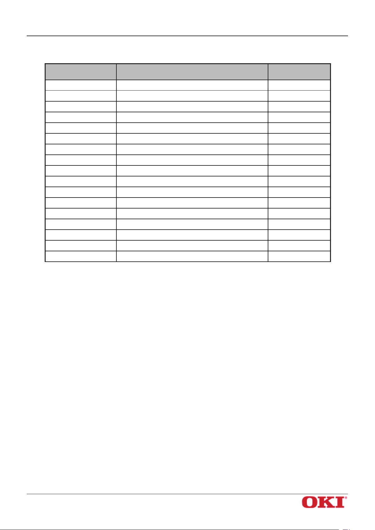
4.2.1 Barcode Font List
The table below shows supported types of barcode fonts and available types of characters.
Barcode Type Character Columns Available Character Set
UPC-E 12 columns Value: 0 to 9
UPC-A 12 columns Value: 0 to 9
JAN/EAN-8 8 columns Value: 0 to 9
Software Manual
JAN/EAN-13 13 columns Value: 0 to 9
Value: 0 to 9
CODE39 More than 1 column
ITF
NW-7 (Codaber) More than 1 column
More than 2 column
(even number)
Symbol: –, ., <SP>, $, /, +, %
Alphabet: A to Z
Start/stop code: * (*1)
Value: 0 to 9
Value: 0 to 9
Symbol: –, $, :, /, ., +,
Alphabet: A to D
*1) Start/stop code is automatically entered, so there is no need to specify it when entering the code.
OKI DATA CORPORATION
- 53 -
Page 57
OKIPOS
PH640
Software Manual
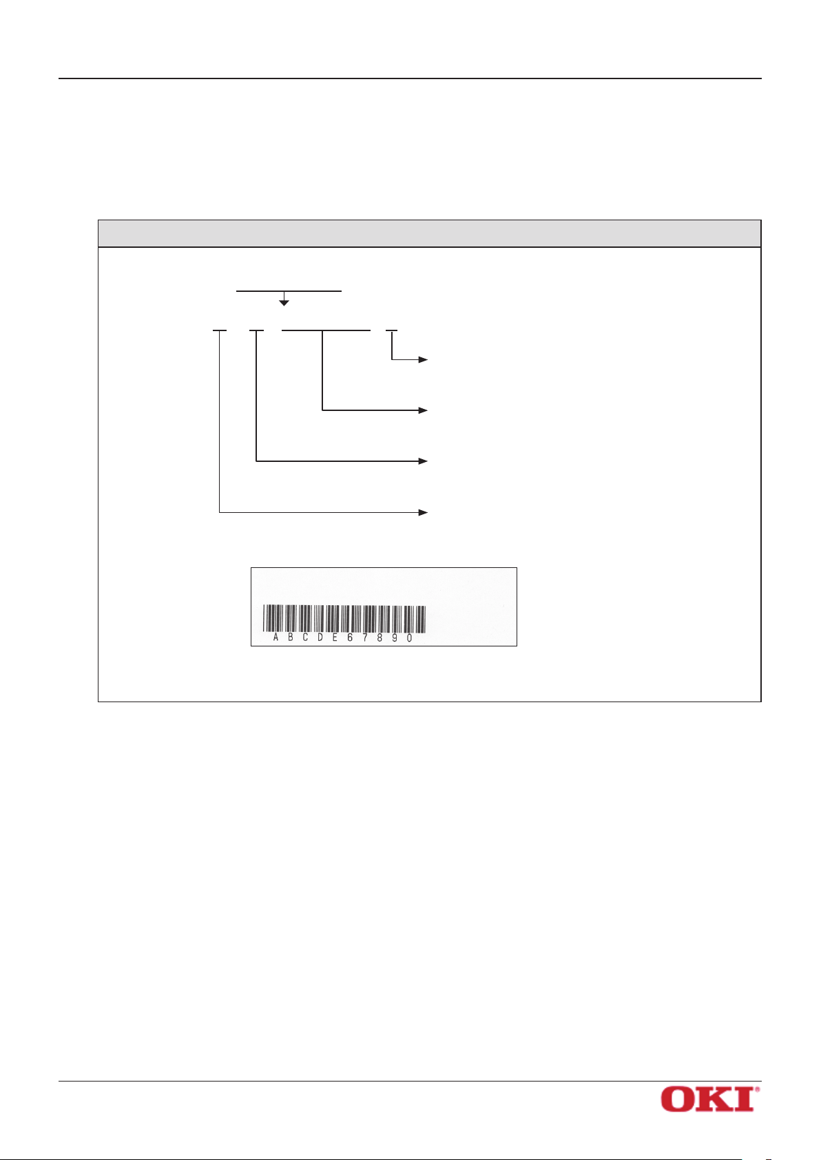
4.2.2 Entering the Barcode Font
Barcode fonts consist of the following parameters that are combined together: the parameter to set
mode, the parameter to set height, the barcode data, and the parameter for barcode end.
Example: To generate the barcode for 'ABCDE67890' using CODE39 (2 dot mode, 8 mm height)
Data to enter: apABCDE67890z
a p ABCDE67890 z
• Parameter for barcode end
Enter “z”.
• Barcode data
Enter actual barcode data.
• Parameter to set height
Specify within the range of “o” to “v”.
• Parameter to set mode
Specify within the range of “a” to “i”.
Print Sample :
For details of each parameter, refer to "4.2.3 Barcode Font Parameter List".
OKI DATA CORPORATION
- 54 -
Page 58

OKIPOS
PH640
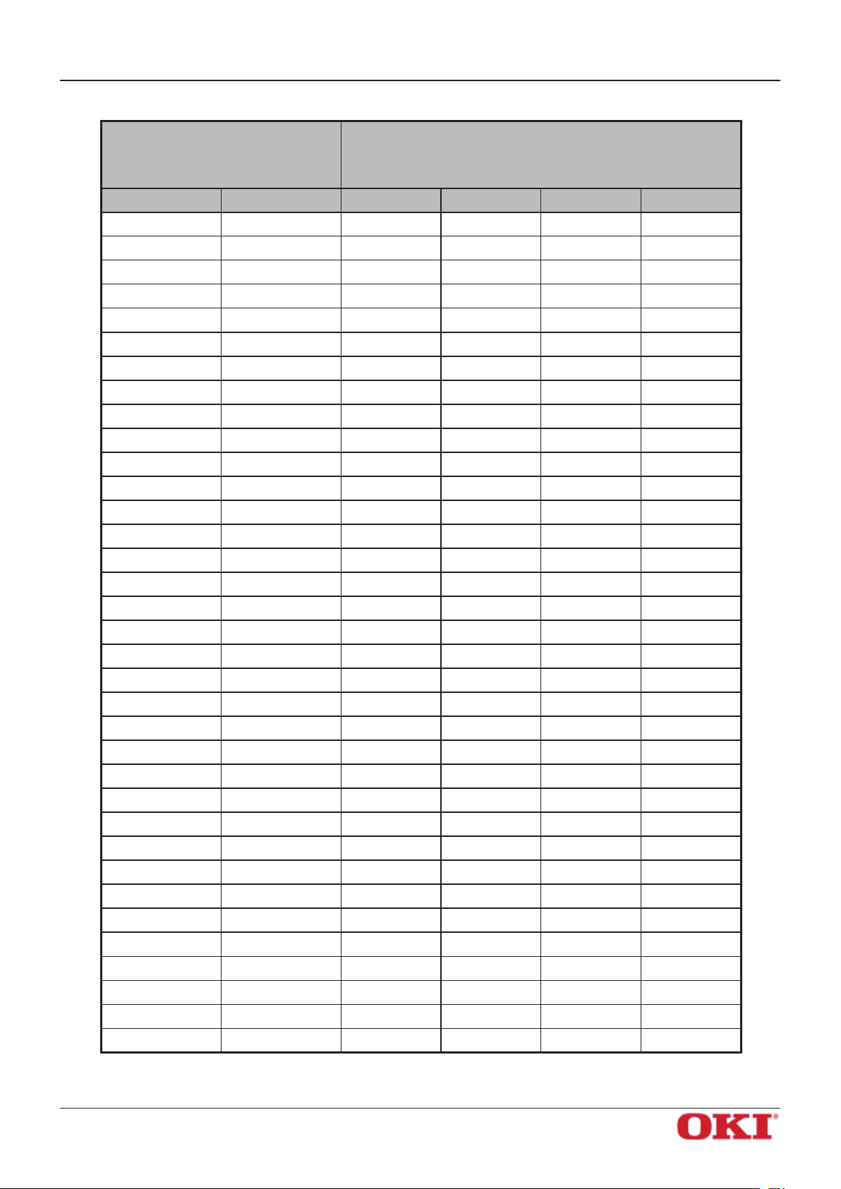
4.2.3 Barcode Font Parameter List
Parameter to set Minimum module width
Software Manual
Character to use barcode
a 2 dots 2 dots (6) 2 dots (5)
b 3 dots 3 dots (9) 4 dots (10)
c 4 dots 4 dots (12) 6 dots (15)
d — 2 dots (5) 2 dots (4)
e — 3 dots (8) 4 dots (8)
f — 4 dots (10) 6 dots (12)
g — 2 dots (4) 2 dots (6)
h — 3 dots (6) 3 dots (9)
i 4 dots (8) 4 dots (12)
UPC-E, UPC-A
JAN/EAN-8,
JAN/EAN-13
CODE39
NW-7
(*1)
*1) Number in () means number of dots with thick pattern.
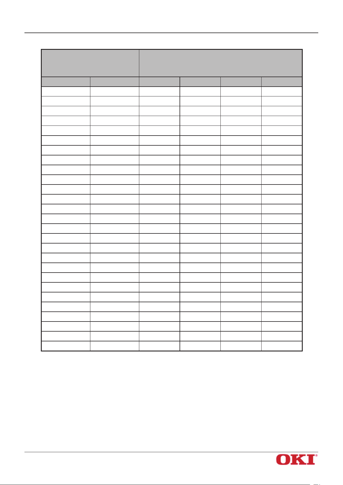
Parameter to set height
Character to use barcode font Barcode height
ITF
(*1)
o Barcode height: 32 dots (4 mm)
p Barcode height: 64 dots (8 mm)
q Barcode height: 96 dots (12 mm)
r Barcode height: 128 dots (16 mm)
s Barcode height: 160 dots (20 mm)
t Barcode height: 192 dots (24 mm)
u Barcode height: 224 dots (28 mm)
v Barcode height: 255 dots (31.9 mm)
Parameter for barcode end
Character to use barcode font Barcode height
z Ending code of barcode data (1 EH)
OKI DATA CORPORATION
- 55 -
Page 59

OKIPOS
PH640
4.2.4 Generating a Barcode Using Microsoft Word
The following is an example of how to set and use barcode fonts.
Select the device font with the barcode name from the font list.
1
In the following example, select the barcode font of CODE39
Software Manual
Note: When using device fonts with Microsoft Word, refer to "6.2 Notes for Using Microsoft
Word".
OKI DATA CORPORATION
- 56 -
Page 60

OKIPOS
PH640
Enter codes.
2
Print.
3
Software Manual
Also, set the font height. (For CODE39, set the font height to “8.5”.)
When printing, a barcode is generated and printed out.
<Print Sample>
OKI DATA CORPORATION
- 57 -
Page 61

OKIPOS
PH640
Software Manual
4.3 Two-dimensional Code Font
The printer driver supports a two-dimensional code font ("QR_CNTL", "PDF417").
This printer driver, when operating in Line mode, is capable of printing QR and PDF417 codes through use
of the appropriate PH640 device fonts.
To print QR code/PDF417, use a two-dimensional code font (“QR_CNTL”, “PDF417”, “DATA1”, “DATA2”,
“DATA3”) and control font (“ESC_FONT”) together.
4.3.1 Two-dimensional Code Font List
Each font has the following features.
Fonts Operation Comments Remarks
QR_CNTL
PDF417
DATA1
DATA2
DATA3
ESC_FONT
QR code
Command setting
PDF417
Command setting
Data setting
Outputs each command for printing
two-dimensional code.
Outputs each command for printing
PDF417.
Replaces ¥x20 ~ ¥x7F with ¥x00 to
¥x5F.
Replaces ¥x20 to ¥x7F with ¥x60 to
¥xBF.
Replaces ¥x20 to ¥x5F with ¥xC0 to
¥xFF.
Outputs without replacing ¥x20 to
¥x7F.
Can output ¥x00
to ¥xFF.
Can output ¥x20
to ¥x7F
OKI DATA CORPORATION
- 58 -
Page 62

OKIPOS
PH640
Software Manual
4.3.2 Entering two-dimensional Code Font
Enter two-dimensional code fonts in the following format.
Set the two-dimensional code type
1
Parameters are set to their default values. Enter only the parameters that you want to change.
Set the two-dimensional code data
2
Enter the barcode cell size, the various parameters, and then the two-dimensional code data.
Get barcode expansion information (optional)
3
The printer returns an error if there is a conict in the settings specied in steps 1 and 2.
Print the two-dimensional code
4
For details of each commands, refer to "Appendix 1. 2-dimensional Codes PDF417 Command Details" and
"Appendix 2. 2-dimensional Codes QR Code Command Details"
Example: To generate a two-dimensional code for '012345ABCD' in QR code (25% error correction rate)
.
Data to enter:
Character to enter Fonts Meaning
1
2
2
2
2
4
*1 Enter '0A', which is the number of bytes of two-dimensional code data (10 bytes) expressed in
hexadecimal notation. Enter the low byte (A) and then the high byte (0).
E2A0* 012345ABCDP
'E2' QR_CNTL Sets the Error Correction level to Q (25%)
'A0' QR_CNTL Sets the QR code data (auto analysis)
'*' DATA1
' ' DATA1
'012345ABCD' ESC_FONT Sets the two-dimensional code data
'P' QR_CNTL Prints the two-dimensional code
Setting the QR code data parameter
A = \x0A = '*' *1
Setting the QR code data parameter
0 = \x00 = ' ' (space) *1
Print Sample :
For details of each fonts, refer to "4.3.3 Two-dimensional Code Command Setting Font".
OKI DATA CORPORATION
- 59 -
Page 63

OKIPOS
PH640
4.3.3 Two-dimensional Code Command Setting Font
QR code setting font (QR_CNTL)
Character to use for the
“QR_CNTL” font
0 For parameters to set the command for each QR code ¥x00
1 For parameters to set the command for each QR code ¥x01
2 For parameters to set the command for each QR code ¥x02
3 For parameters to set the command for each QR code ¥x03
4 For parameters to set the command for each QR code ¥x04
5 For parameters to set the command for each QR code ¥x05
6 For parameters to set the command for each QR code ¥x06
7 For parameters to set the command for each QR code ¥x07
8 For parameters to set the command for each QR code ¥x08
9 For parameters to set the command for each QR code ¥x09
Operation Code output by the driver
Software Manual
M Model setting of QR code ¥x1b¥x1dyS0
M1 Model setting of QR code: Model 1 ¥x1b¥x1dyS0¥x01
M2 Model setting of QR code: Model 2 ¥x1b¥x1dyS0¥x02
E Correction level setting ¥x1b¥x1dyS1
* El(E0) Correction level L (Correction rate 7%) ¥x1b¥x1dyS1¥x00
*Em(E1) Correction level M (Correction rate 15%) ¥x1b¥x1dyS1¥x01
* Eq(E2) Correction level Q (Correction rate 25%) ¥x1b¥x1dyS1¥x02
* Eh(E3) Correction level H (Correction rate 30%) ¥x1b¥x1dyS1¥x03
S1 to S8 Module size setting (unit: dot) ¥x1b¥x1dyS2(¥x01 to 08)
A0 QR code data setting (data automatic analysis) ¥x1b¥x1dyD1¥x00
B QR code data setting (data manual analysis) ¥x1b¥x1dyD2
P QR code printing ¥x1b¥x1dyP
*) The correction level can be set using the method in ().
OKI DATA CORPORATION
- 60 -
Page 64
OKIPOS
PH640
PDF417 setting font (PDF417)
Character to use for the
“PDF417” font
0 For parameters to set the command for each PDF417 ¥x00
1 For parameters to set the command for each PDF417 ¥x01
2 For parameters to set the command for each PDF417 ¥x02
3 For parameters to set the command for each PDF417 ¥x03
4 For parameters to set the command for each PDF417 ¥x04
5 For parameters to set the command for each PDF417 ¥x05
6 For parameters to set the command for each PDF417 ¥x06
7 For parameters to set the command for each PDF417 ¥x07
8 For parameters to set the command for each PDF417 ¥x08
9 For parameters to set the command for each PDF417 ¥x09
S Setting PDF417 barcode size ¥x1b¥x1dxS0
E Setting PDF417 security level (ECC) ¥x1b¥x1dxS1
Operation
Software Manual
Code output by the
driver
M Setting X-direction size of PDF417 module ¥x1b¥x1dxS2
A Setting aspect ratio of PDF417 module ¥x1b¥x1dxS3
D Setting PDF417 barcode data ¥x1b¥x1dxD
P Prints PDF417 barcode ¥x1b¥x1dxP
I Acquires explanatory information of PDF417 barcode ¥x1b¥x1dxI
OKI DATA CORPORATION
- 61 -
Page 65

OKIPOS
PH640
Two-dimensional Code Data Setting Font (DATA1, DATA2, DATA3, ESC_FONT)
Software Manual
Data to enter
Character information specified by
the user in applications (Word, VB,
etc.)
Character Character code ESC_FONT DATA1 DATA2 DATA3
Blank ¥x20 ¥x20 ¥x00 ¥x60 ¥xC0
! ¥x21 ¥x21 ¥x01 ¥x61 ¥xC1
“ ¥x22 ¥x22 ¥x02 ¥x62 ¥xC2
# ¥x23 ¥x23 ¥x03 ¥x63 ¥xC3
$ ¥x24 ¥x24 ¥x04 ¥x64 ¥xC4
% ¥x25 ¥x25 ¥x05 ¥x65 ¥xC5
& ¥x26 ¥x26 ¥x06 ¥x66 ¥xC6
‘ ¥x27 ¥x27 ¥x07 ¥x67 ¥xC7
( ¥x28 ¥x28 ¥x08 ¥x68 ¥xC8
) ¥x29 ¥x29 ¥x09 ¥x69 ¥xC9
* ¥x2A ¥x2A ¥x0A ¥x6A ¥xCA
+ ¥x2B ¥x2B ¥x0B ¥x6B ¥xCB
, ¥x2C ¥x2C ¥x0C ¥x6C ¥xCC
- ¥x2D ¥x2D ¥x0D ¥x6D ¥xCD
Data to output
Character code to actually output to the printer by the printer
driver
. ¥x2E ¥x2E ¥x0E ¥x6E ¥xCE
/ ¥x2F ¥x2F ¥x0F ¥x6F ¥xCF
0 ¥x30 ¥x30 ¥x10 ¥x70 ¥xD0
1 ¥x31 ¥x31 ¥x11 ¥x71 ¥xD1
2 ¥x32 ¥x32 ¥x12 ¥x72 ¥xD2
3 ¥x33 ¥x33 ¥x13 ¥x73 ¥xD3
4 ¥x34 ¥x34 ¥x14 ¥x74 ¥xD4
5 ¥x35 ¥x35 ¥x15 ¥x75 ¥xD5
6 ¥x36 ¥x36 ¥x16 ¥x76 ¥xD6
7 ¥x37 ¥x37 ¥x17 ¥x77 ¥xD7
8 ¥x38 ¥x38 ¥x18 ¥x78 ¥xD8
9 ¥x39 ¥x39 ¥x19 ¥x79 ¥xD9
: ¥x3A ¥x3A ¥x1A ¥x7A ¥xDA
; ¥x3B ¥x3B ¥x1B ¥x7B ¥xDB
< ¥x3C ¥x3C ¥x1C ¥x7C ¥xDC
= ¥x3D ¥x3D ¥x1D ¥x7D ¥xDD
> ¥x3E ¥x3E ¥x1E ¥x7E ¥xDE
? ¥x3F ¥x3F ¥x1F ¥x7F ¥xDF
@ ¥x40 ¥x40 ¥x20 ¥x80 ¥xE0
A ¥x41 ¥x41 ¥x21 ¥x81 ¥xE1
OKI DATA CORPORATION
- 62 -
Page 66
OKIPOS
PH640
Software Manual
Data to enter
Character information specified by
the user in applications (Word, VB,
etc.)
Character Character code ESC_FONT DATA1 DATA2 DATA3
B ¥x42 ¥x42 ¥x22 ¥x82 ¥xE2
C ¥x43 ¥x43 ¥x23 ¥x83 ¥xE3
D ¥x44 ¥x44 ¥x24 ¥x84 ¥xE4
E ¥x45 ¥x45 ¥x25 ¥x85 ¥xE5
F ¥x46 ¥x46 ¥x26 ¥x86 ¥xE6
G ¥x47 ¥x47 ¥x27 ¥x87 ¥xE7
H ¥x48 ¥x48 ¥x28 ¥x88 ¥xE8
I ¥x49 ¥x49 ¥x29 ¥x89 ¥xE9
J ¥x4A ¥x4A ¥x2A ¥x8A ¥xEA
K ¥x4B ¥x4B ¥x2B ¥x8B ¥xEB
L ¥x4C ¥x4C ¥x2C ¥x8C ¥xEC
M ¥x4D ¥x4D ¥x2D ¥x8D ¥xED
N ¥x4E ¥x4E ¥x2E ¥x8E ¥xEE
O ¥x4F ¥x4F ¥x2F ¥x8F ¥xEF
Data to output
Character code to actually output to the printer by the printer
driver
P ¥x50 ¥x50 ¥x30 ¥x90 ¥xF0
Q ¥x51 ¥x51 ¥x31 ¥x91 ¥xF1
R ¥x52 ¥x52 ¥x32 ¥x92 ¥xF2
S ¥x53 ¥x53 ¥x33 ¥x93 ¥xF3
T ¥x54 ¥x54 ¥x34 ¥x94 ¥xF4
U ¥x55 ¥x55 ¥x35 ¥x95 ¥xF5
V ¥x56 ¥x56 ¥x36 ¥x96 ¥xF6
W ¥x57 ¥x57 ¥x37 ¥x97 ¥xF7
X ¥x58 ¥x58 ¥x38 ¥x98 ¥xF8
Y ¥x59 ¥x59 ¥x39 ¥x99 ¥xF9
Z ¥x5A ¥x5A ¥x3A ¥x9A ¥xFA
[ ¥x5B ¥x5B ¥x3B ¥x9B ¥xFB
¥ ¥x5C ¥x5C ¥x3C ¥x9C ¥xFC
] ¥x5D ¥x5D ¥x3D ¥x9D ¥xFD
^ ¥x5E ¥x5E ¥x3E ¥x9E ¥xFE
_ ¥x5F ¥x5F ¥x3F ¥x9F ¥xFF
` ¥x60 ¥x60 ¥x40 ¥xA0 -
a ¥x61 ¥x61 ¥x41 ¥xA1 -
b ¥x62 ¥x62 ¥x42 ¥xA2 -
c ¥x63 ¥x63 ¥x43 ¥xA3 -
d ¥x64 ¥x64 ¥x44 ¥xA4 -
OKI DATA CORPORATION
- 63 -
Page 67
OKIPOS
PH640
Software Manual
Data to enter
Character information specified by
the user in applications (Word, VB,
etc.)
Character Character code ESC_FONT DATA1 DATA2 DATA3
e ¥x65 ¥x65 ¥x45 ¥xA5 -
f ¥x66 ¥x66 ¥x46 ¥xA6 -
g ¥x67 ¥x67 ¥x47 ¥xA7 -
h ¥x68 ¥x68 ¥x48 ¥xA8 -
i ¥x69 ¥x69 ¥x49 ¥xA9 -
j ¥x6A ¥x6A ¥x4A ¥xAA -
k ¥x6B ¥x6B ¥x4B ¥xAB -
l ¥x6C ¥x6C ¥x4C ¥xAC -
m ¥x6D ¥x6D ¥x4D ¥xAD -
n ¥x6E ¥x6E ¥x4E ¥xAE -
o ¥x6F ¥x6F ¥x4F ¥xAF -
p ¥x70 ¥x70 ¥x50 ¥xB0 -
q ¥x71 ¥x71 ¥x51 ¥xB1 -
r ¥x72 ¥x72 ¥x52 ¥xB2 -
Data to output
Character code to actually output to the printer by the printer
driver
s ¥x73 ¥x73 ¥x53 ¥xB3 -
t ¥x74 ¥x74 ¥x54 ¥xB4 -
u ¥x75 ¥x75 ¥x55 ¥xB5 -
v ¥x76 ¥x76 ¥x56 ¥xB6 -
w ¥x77 ¥x77 ¥x57 ¥xB7 -
x ¥x78 ¥x78 ¥x58 ¥xB8 -
y ¥x79 ¥x79 ¥x59 ¥xB9 -
z ¥x7A ¥x7A ¥x5A ¥xBA -
{ ¥x7B ¥x7B ¥x5B ¥xBB -
| ¥x7C ¥x7C ¥x5C ¥xBC -
} ¥x7D ¥x7D ¥x5D ¥xBD -
~ ¥x7E ¥x7E ¥x5E ¥xBE -
< DEL > * ¥x7F ¥x7F ¥x5F ¥xBF -
* Cannot be entered using a character.
OKI DATA CORPORATION
- 64 -
Page 68
OKIPOS
PH640
Software Manual
4.3.4 Using the Two-dimensional Code Font
When using the QR code/PDF417 font, data of the two-dimensional code can be specified up to 500
bytes. (500 bytes includes the types of data entered and the separator.)
A sample program for Visual Basic using two-dimensional code font is provided below.
QR code print—Sample 1 (QR code data setting: For data manual analysis setting)
Private Sub Command1_Click()
Printer.Font.Name = "Printer 17cpi Tall"
Printer.Print "QR Code Test Print for VB 6.0"
Printer.Font.Name = "Printer 17cpi"
Printer.Print
Printer.Print "DATA:"
Printer.Print "abcdefghij"
Printer.Print
Printer.Print "QR code:";
Printer.Font.Name = "QR_CNTL" ' Sets QR_CNTL font
Printer.Print "M2"; ' Sets barcode model
Printer.Print "Em"; ' Sets correction level (Correction rate 15%)
Printer.Print "S3" ' Sets module size (Module size 3 dots)
Printer.Print "B1"; ' Sets barcode data (Manual analysis) + Number of blocks
Printer.Print "2"; ' Alphanumeric (Data type)
Printer.Font.Name = "DATA1" ' DATA1 = 0x0000 - 0x005F
Printer.Print Chr(&H2A); '
Printer.Print Chr(&H20); '
Printer.Font.Name = "ESC_FONT" ' ESC_FONT = 0x0020 - 0x007F
Printer.Print "abcdefghij"; ' Barcode data (10 byte)
Printer.Font.Name = "QR_CNTL" ' Sets QR_CNTL font
Printer.Print "P" ' Prints barcode data
Printer.EndDoc
End Sub
Converts 0x2A0x0A, 0x200x0
Number of bytes: 10(0x0A)+0(0x0)=10 byte
When QR code data is set to data manual analysis, be sure to set the number of blocks and
type of data to enter.
For details on setup, refer to "Appendix 1. 2-dimensional Codes PDF417 Command Details"
and "Appendix 2. 2-dimensional Codes QR Code Command Details".
OKI DATA CORPORATION
- 65 -
Page 69

OKIPOS
PH640
QR code print—Sample 2 (QR code data setting: For data automatic analysis setting)
Private Sub Command2_Click()
Printer.Font.Name = "Printer 17cpi Tall"
Printer.Print "QR Code Test Print for VB 6.0"
Printer.Font.Name = "Printer 17cpi"
Printer.Print
Printer.Print "DATA:"
Printer.Print "abcdefghij"
Printer.Print
Printer.Print "QR code:";
Printer.Font.Name = "QR_CNTL" ' Sets QR_CNTL font
Printer.Print "M1"; ' Sets barcode model
Printer.Print "Eq"; ' Sets correction level (Correction rate 25%)
Printer.Print "S7" ' Sets module size (Module size 7 dots)
Software Manual
Printer.Print "A0"; ' Sets barcode data (Automatic analysis)
Printer.Font.Name = "DATA1" ' DATA1 = 0x0000 - 0x005F
Printer.Print Chr(&H2A); '
Printer.Print Chr(&H20); '
Printer.Font.Name = "ESC_FONT" ' ESC_FONT = 0x0020 - 0x007F
Printer.Print "abcdefghij"; ' Barcode data (10 byte)
Printer.Font.Name = "QR_CNTL" ' Sets QR_CNTL font
Printer.Print "P" ' Prints barcode data
Printer.EndDoc
End Sub
Converts 0x2A0x0A, 0x200x0
Number of bytes: 10(0x0A)+0(0x0)=10 byte
OKI DATA CORPORATION
- 66 -
Page 70

OKIPOS
PH640
PDF417 print — Sample 1
Private Sub Command4_Click()
Printer.Font.Name = "Printer 17cpi Tall"
Printer.Print "PDF417 Test Print for VB 6.0"
Printer.Font.Name = "Printer 17cpi"
Printer.Print
Printer.Print "DATA:"
Printer.Print "1234567890"
Printer.Print
Printer.Print "PDF417:";
Printer.Font.Name = "PDF417"
Printer.Print "S023"; ' Sets barcode size
Printer.Print "E3"; ' Sets ECC level
Printer.Print "M3" ' Sets X-direction size of the module
Printer.Print "A3" ' Sets aspect ratio of the module
Printer.Print "D"; ' Sets barcode data
Software Manual
Printer.Font.Name = "DATA1" ' DATA1 = 0x0000 - 0x005F
Printer.Print Chr(&H2A); ' Number of bytes of barcode data
Printer.Print Chr(&H20);
Printer.Font.Name = "ESC_FONT" ' ESC_FONT = 0x0020 - 0x007F
Printer.Print "1234567890";
Printer.Font.Name = "PDF417"
Printer.Print "P" ' Prints barcode data
Printer.EndDoc
End Sub
OKI DATA CORPORATION
- 67 -
Page 71

OKIPOS
PH640
PDF417 print — Sample 2
Private Sub Command5_Click()
Printer.Font.Name = "Printer 17cpi Tall"
Printer.Print "PDF417 Test Print for VB 6.0"
Printer.Font.Name = "Printer 17cpi"
Printer.Print
Printer.Print "DATA:"
Printer.Print "abcdefghij"
Printer.Print
Printer.Print "PDF417:";
Printer.Font.Name = "PDF417"
Printer.Print "S023"; ' Sets barcode size
Printer.Print "E3"; ' Sets ECC level
Printer.Print "M3" ' Sets X-direction size of the module
Printer.Print "A3" ' Sets aspect ratio of the module
Software Manual
Printer.Print "D"; ' Sets barcode data
Printer.Font.Name = "DATA1" ' DATA1 = 0x0000 - 0x005F
Printer.Print Chr(&H2A); ' Number of bytes of barcode data
Printer.Print Chr(&H20);
Printer.Font.Name = "ESC_FONT" ' ESC_FONT = 0x0020 - 0x007F
Printer.Print "abcdefghij";
Printer.Font.Name = "PDF417"
Printer.Print "P" ' Prints barcode data
Printer.EndDoc
End Sub
OKI DATA CORPORATION
- 68 -
Page 72

OKIPOS
PH640
Software Manual
4.4 Control Fonts
This printer driver provides a control font that can be used during operation in Line mode.
The control font is used to execute various printer actions, and is not used for printing. Each character is
the font is associated with a particular action.
4.4.1 Control Font Characters and Their Operations
The operations that can be executed through the control font are shown below.
Character Operation
A Drive cash drawer 1 (50 ms)
B Drive cash drawer 1 (100 ms)
C Drive cash drawer 1 (150 ms)
D Drive cash drawer 1 (200 ms)
E Drive cash drawer 1 (250 ms)
d Drive cash drawer 2 (200 ms)
6 Output LF
7 Output CR
F Auto-cutter: Full-cut
P Auto-cutter: Partial-cut
G Print NV Bit Image 1 in regular mode
H Print NV Bit Image 2 in regular mode
I Print NV Bit Image 3 in regular mode
J Print NV Bit Image 4 in regular mode
K Print NV Bit Image 5 in regular mode
Q Print NV Bit Image 1 in double-width mode
R Print NV Bit Image 2 in double-width mode
S Print NV Bit Image 3 in double-width mode
T Print NV Bit Image 4 in double-width mode
U Print NV Bit Image 5 in double-width mode
V Print NV Bit Image 1 in double-height mode
W Print NV Bit Image 2 in double-height mode
X Print NV Bit Image 3 in double-height mode
Y Print NV Bit Image 4 in double-height mode
Z Print NV Bit Image 5 in double-height mode
[ Print NV Bit Image 1 in 4x mode
] Print NV Bit Image 2 in 4x mode
OKI DATA CORPORATION
- 69 -
Page 73

OKIPOS
PH640
Software Manual
Character Operation
^ Print NV Bit Image 3 in 4x mode
_ Print NV Bit Image 4 in 4x mode
` Print NV Bit Image 5 in 4x mode
a Align left
b Align center
c Align right
e Set new line to 3 mm (1/8 inch)
f Set new line to 4 mm (1/6 inch)
g International character select: USA
h International character select: France
i International character select: Germany
j International character select: England
k International character select: Denmark I
l International character select: Sweden
m International character select: Italy
n International character select: Spain I
o International character select: Japan
p International character select: Norway
q International character select: Denmark II
r International character select: Spain II
s International character select: Latin America
t Print using black/white inversion
u Cancel black/white inversion
v Customer display: Start data transfer
w Customer display: End data transfer
x Customer display: Display clear
Note: The printer ignores control font characters that it does not support.
OKI DATA CORPORATION
- 70 -
Page 74

OKIPOS
PH640
4.4.2 Using the Control Font with Microsoft Word
The following is an example of how to use the control font.
Select the Control font from the font list.
1
Software Manual
Note: When using device fonts with Microsoft Word, refer to "6.2 Notes for Using Microsoft
Word".
OKI DATA CORPORATION
- 71 -
Page 75

OKIPOS
PH640
Input the character for each operation you wish to execute (refer to "4.4.1 Control Font Characters
2
Software Manual
and Their Operations").
6: Output LF
b: Align center
Type characters in a font other than the
control font
For the characters that set the control font, set the font height to the specified value “8.5”.
Print.
3
In this example, the printer executes a linefeed and then prints ABC at the center of the page.
<Print Sample>
OKI DATA CORPORATION
- 72 -
Page 76

OKIPOS
PH640
4.5 Restrictions and Precautions
• Please do not use more than one device font on a single line.
Mixing device fonts on a single line may result in skewed printing.
• Do not include graphic data (Windows fonts, ruled lines, etc.) on the same line with a device font, as
this too may cause skewed print results.
• Remember that the “Control” device font cannot be used for normal character printing.
Use fonts other than the “Control” device font to print characters.
• If you use barcode fonts or two-dimensional code fonts, only the characters corresponding to the
codes that you enter appear in the document window of software applications, such as Microsoft
Word. The barcode image is generated when you print it.
• If you print barcodes or two-dimensional bar codes using the device fonts, they may not be printed
with the correct page length.
Software Manual
• To print two-dimensional codes using the device fonts, enter the two-dimensional code data on
one line.
Keep the size of the two-dimensional code data within 500 bytes. This data size limit is determined
by the printable width of the paper that you will be printing on. 500 bytes is based on a printable
width of 104 mm. If you use paper whose printable width is less than 104 mm, you may not be able
to print data that is 500 bytes in size.
This limitation also applies to VB programs. When sending data using a VB program, keep the data
length within 500 bytes.
If you enter two-dimensional code data that spans multiple lines or specify data that exceeds
500 bytes, the two-dimensional code will not be printed properly, and there is no guarantee that
anything that comes after it will be printed properly.
OKI DATA CORPORATION
- 73 -
Page 77

OKIPOS
PH640
5. OKIPOS PH640 Conguration Utility
(Windows 2000 SP3 or Later/XP/Vista 32-Bit Edition/7 32-Bit Edition)
This software is supported by Windows 2000 (SP3 or later)/XP/Vista 32-bit edition/7 32-bit edition.
The OKIPOS PH640 Conguration Utility allows you to set a variety of print-related settings.
Open the Printer Conguration Utility dialog as follows.
Windows Vista 32-Bit Edition and 7 32-Bit Edition
A. From the Windows Start menu
From the Windows Start menu, select All Programs – Okidata – OKIPOS PH640 – Utility – OKIPOS
PH640 Conguration Utility.
Software Manual
In the User Account Control dialog box, click the Allow or Yes button.
B. From the Printer properties
1. On the taskbar, click Start. On Windows Vista, click Control Panel, and then click Printer to open
the printers folder. On Windows 7, click Devices and Printers to open the printers folder.
2. Right-click the printer icon to display the drop-down menu. On Windows Vista, click Run as
administrator, and then click Properties. On Windows 7, Click Printer properties(, select the
Printer Queue name).
< On Windows Vista > < On Windows 7 with USB interface >
OKI DATA CORPORATION
- 74 -
Page 78

OKIPOS
PH640
3. If you are using Windows Vista, the User Account Control dialog appears. Click Continue.
4. Click the OKIPOS PH640 Cong tab, and click Launch Conguration Utility.
Software Manual
5. If you are using Windows 7, the User Account Control dialog appears. Click Yes.
6. The OKIPOS PH640 Conguration Utility dialog box appears.
Important: If you are using Windows 32-bit Vista, you must select Run as administrator
when opening the Properties dialog. If you do not run these operations as
administrator, any changes that you make may not work as expected.
OKI DATA CORPORATION
- 75 -
Page 79

OKIPOS
PH640
Windows 2000 SP3 or Later/XP
A. From the Windows Start menu
At the Windows Start menu, select All Programs — Okidata — Utility — OKIPOS PH640 Conguration Utility.
B. From the Printer properties
1. From the Windows Start menu, select Printers and Faxes to open the folder.
2. In the folder, right-click the printer icon, and then select Properties to open the printer’s Properties
dialog box.
3. Click the OKIPOS PH640 Cong tab, and click Launch Conguration Utility.
Software Manual
4. The OKIPOS PH640 Conguration Utility dialog box appears.
OKI DATA CORPORATION
- 76 -
Page 80
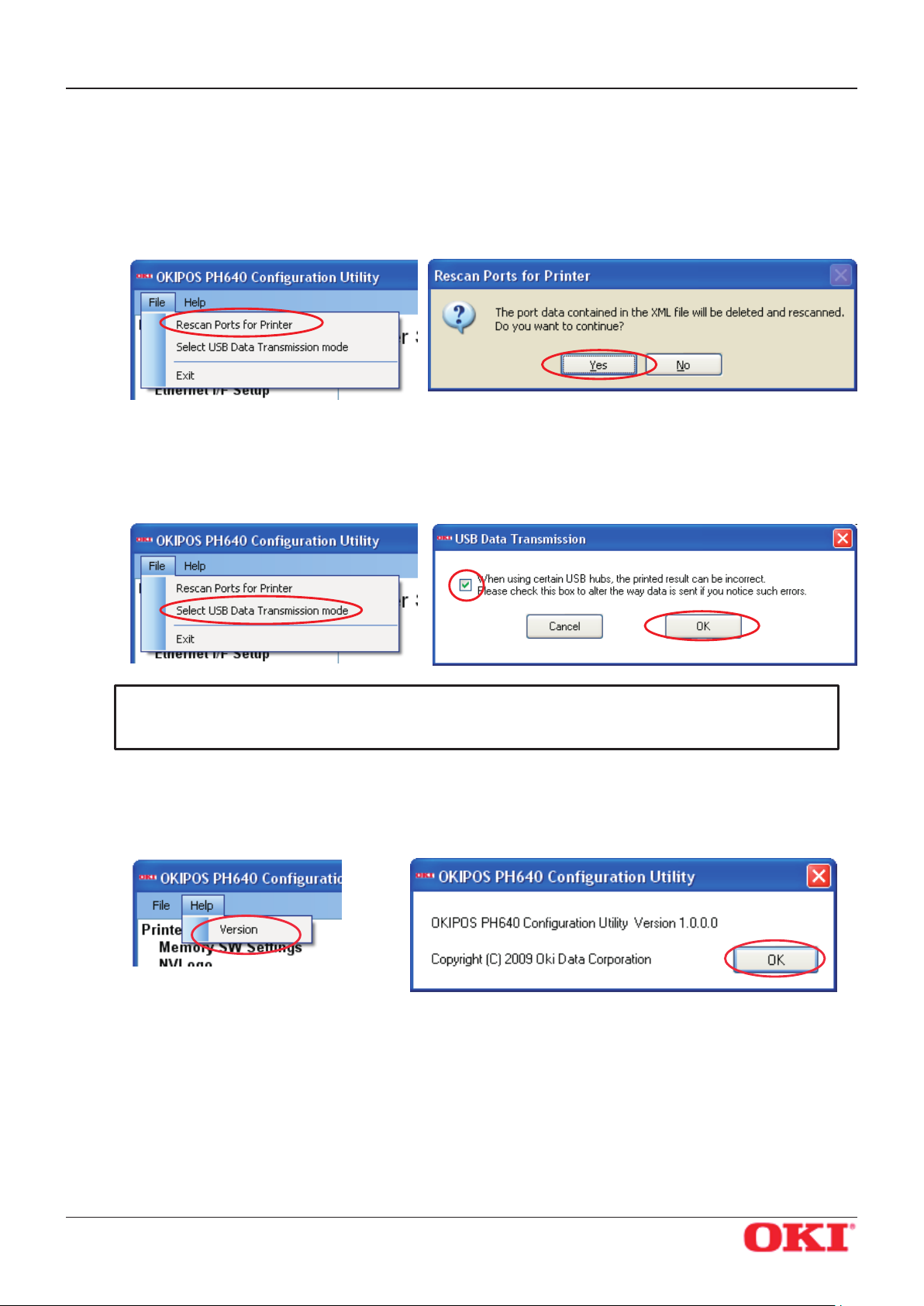
OKIPOS
PH640
Menu Bar
(1) File
• Rescan Ports for Printer
Rescans the ports.
To rescan, click Yes.
• Select USB Data Transmission Mode
You can use this feature to set a smaller transmission size. In some cases, use of USB hubs may
cause incorrect printing. If you are having this problem, check the checkbox.
Software Manual
Important: Checking the USB transmission mode checkbox may in some cases cause a
drop in the printing speed.
(2) Help
• Version
Select Help — Version to display the version of OKIPOS PH640 Conguration Utility.
OKI DATA CORPORATION
- 77 -
Page 81
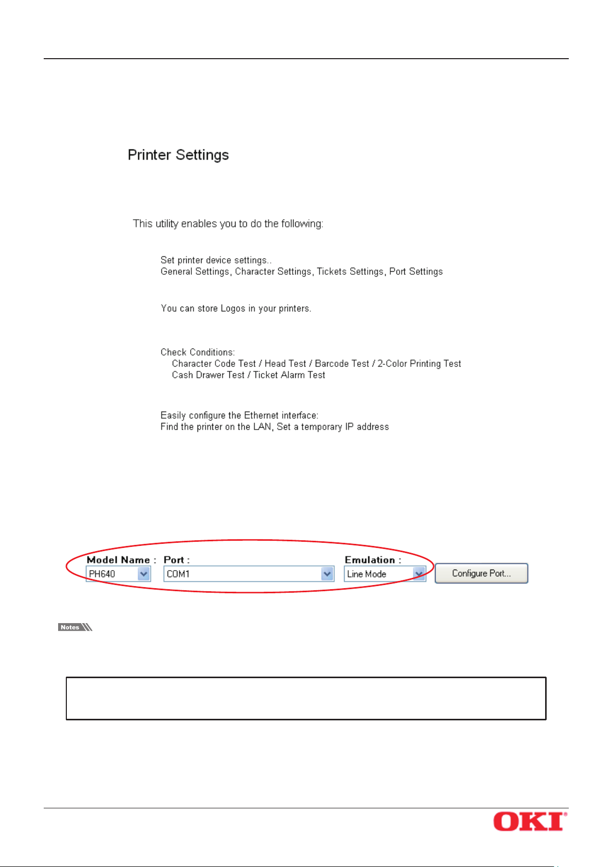
OKIPOS
PH640
Software Manual
5.1 Printer Settings
Use the printer settings to set the memory switches, set up NV logos, carry out printer tests, and congure
the Ethernet interface.
If you select any of the items, the top part of the dialog box will display the name of the connected printer,
the name of the port it is connected to, the current emulation, and a Congure Port button.
Select the model name, port name, and emulation according to the environment used.
Printer settings correspond to usage in Line Mode and ESC/POS Mode. Select the emulation, and make
settings at the printer side, in accordance with the application you are using.
Important: When using an Ethernet interface, the TCP/IP port will appear in the Port list
by clicking the Search LAN for Printers button in Ethernet I/F Setup.
OKI DATA CORPORATION
- 78 -
Page 82
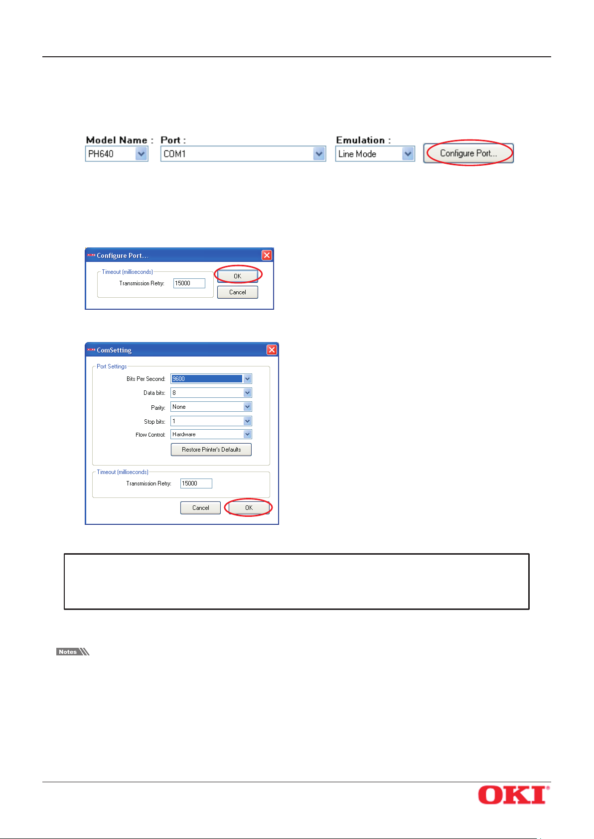
OKIPOS
PH640
Click the Congure Port button to display the conguration dialog box for the selected port. After making
the appropriate settings, click the OK button.
<LPT> <USB> <TCP/IP>
Software Manual
<COM>
Important: Match the port congurations to the printer settings.
The printer settings can be conrmed using the self-printing.
For details, refer to the Hardware Manual.
In the conguration utility, the Flow Control for the serial interface cannot be set to Xon/Xo. If the printer
setting is Xon/Xo, change it to DTR and set the port conguration setting to Hardware.
OKI DATA CORPORATION
- 79 -
Page 83
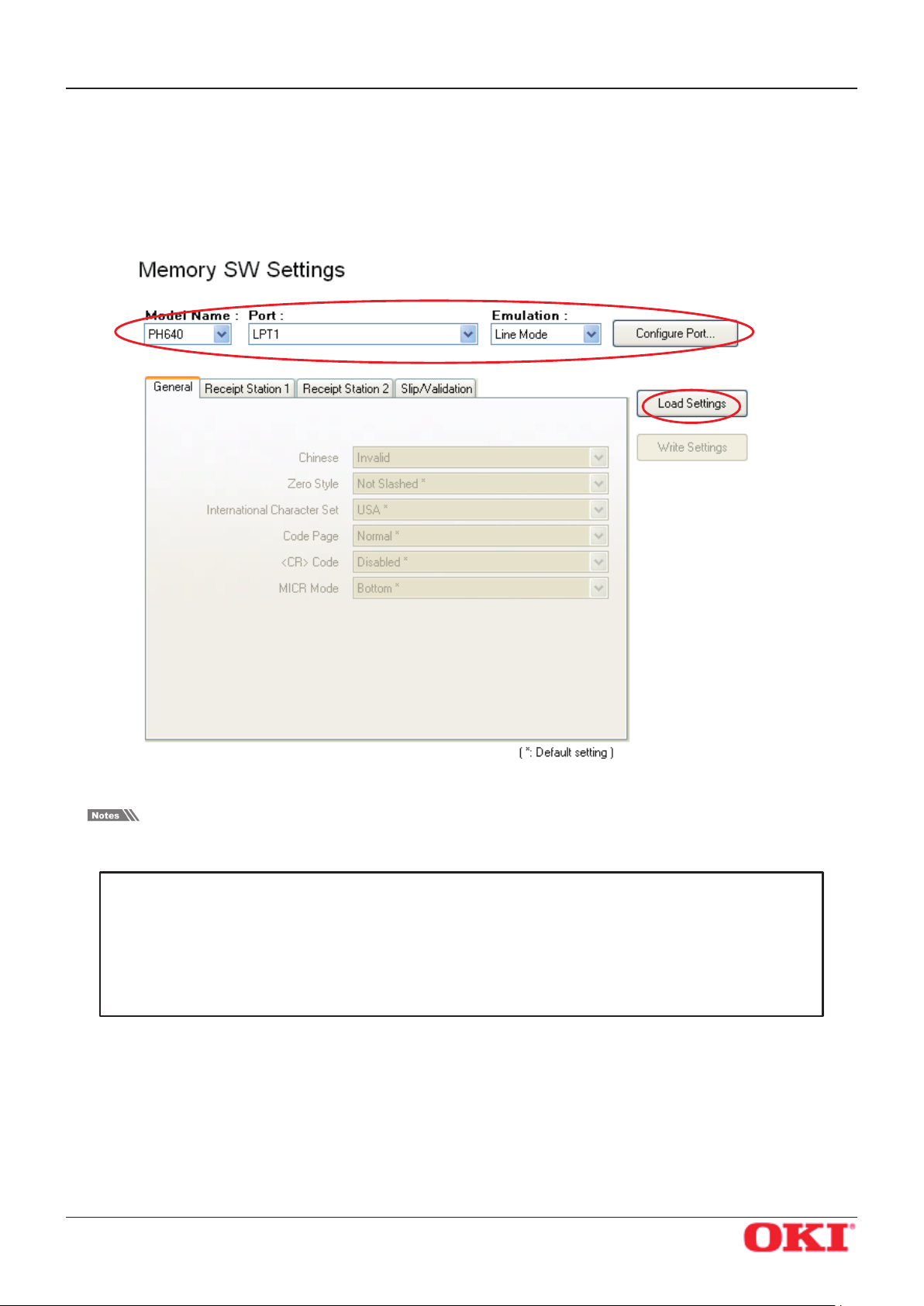
OKIPOS
PH640
Software Manual
5.1.1 Memory SW Settings
In Memory SW Settings, the printer memory switch settings can be loaded and written.
Select the model name, port name, and emulation according to the environment used, and then click the
Load Settings button to read the printer’s current memory switch settings.
Values marked with * are the factory defaults.
Important: 1 Before clicking the button to load the settings, conrm that the model
name, port name, and emulation settings match the printer settings.
2 The memory switch settings cannot be used for virtual serial ports.
3 The memory switch loading will fail if the printer status function is in
use. In this case, just click the “Load Setting” and try again.
OKI DATA CORPORATION
- 80 -
Page 84
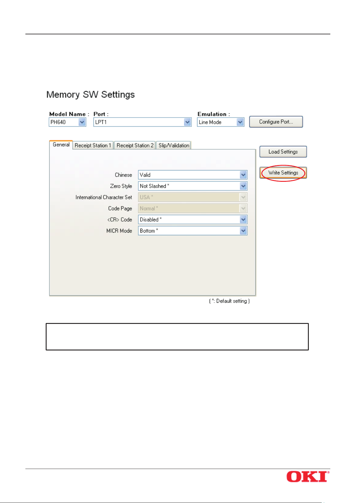
OKIPOS
PH640
To change the memory switch settings, select items to change from the drop-down menus, and then click
the Write Settings button.
The displayed settings are written to the printer.
Software Manual
Important: Click the Write Settings button to make your changes eective.
After changing the settings, be sure to click the Write Settings button.
OKI DATA CORPORATION
- 81 -
Page 85
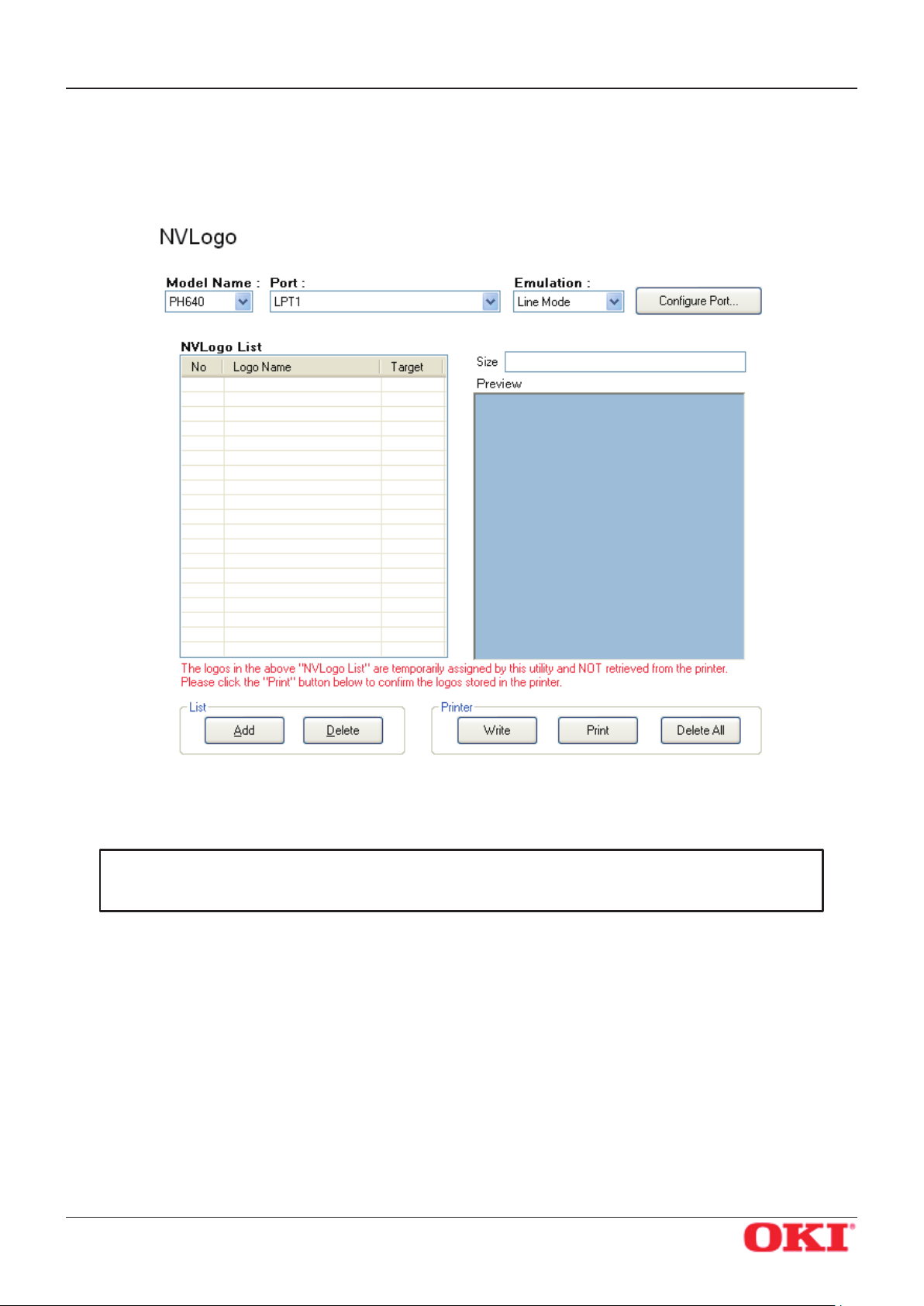
OKIPOS
PH640
Software Manual
5.1.2 NVLogo
NVLogo is a function for registering image data, selected from data pre-registered in the Image List, to the
printer in order to print them on the top or bottom of the page.
For details about adding image data to the NVLogo list, refer to “5.3.1 Image List”.
To set the print data of NV logos, use the printer driver.
For details, refer to the information in “3.2.10 Document Top Logo” to “3.2.13 Document Bottom Logo”.
Important: The “NVLogo List” is a list of the data registered in the computer.
To check the images registered in the printer, click the Print button.
OKI DATA CORPORATION
- 82 -
Page 86
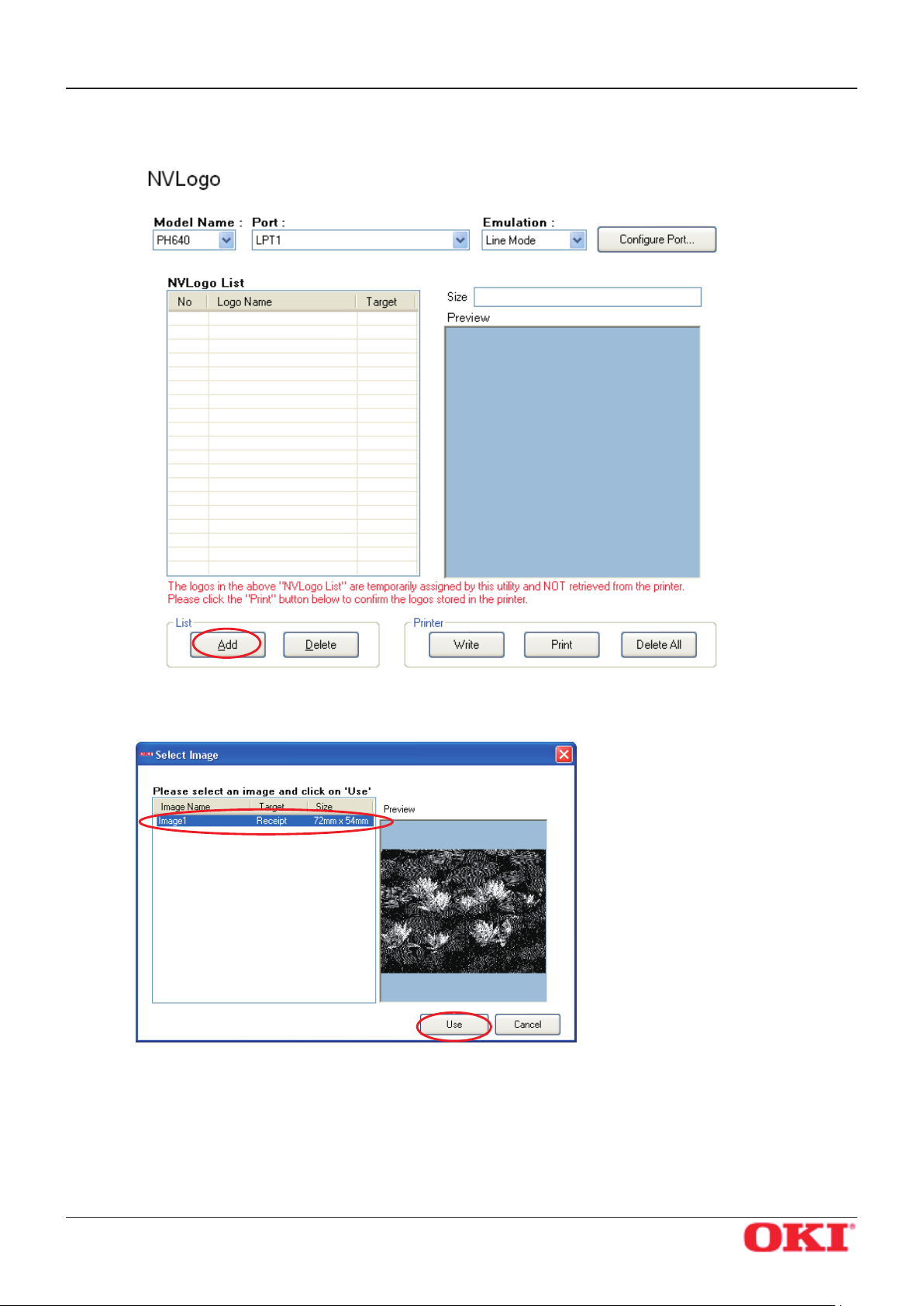
OKIPOS
PH640
1 Click the Add button.
Software Manual
2 Select the image that you want to register in the printer, and then click the Use button.
OKI DATA CORPORATION
- 83 -
Page 87
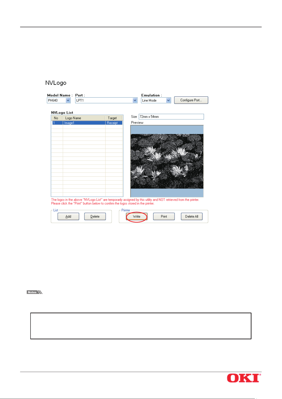
OKIPOS
PH640
3 The selected graphic data is added to the NVLogo List.
4 When you have moved all graphic data to register into the NVLogo List, click the Write button. Data
Software Manual
To register multiple images in the printer, repeat steps 1 and 2.
To delete the selected image from the NVLogo List, click the Delete button.
shown in the NVLogo List is written to the printer.
Clicking the Print button will generate a thermal printout of all of the NV logo data written to the
printer. This makes it possible for you to check all of the image data currently registered in the printer.
Note that the printout of logos that are registered for slip printout will not look the same as they do
on slips, since the print density of the thermal printer is dierent.
To delete all of the NV logo data in the printer, click the Delete All button.
The memory capacity for NV logos in this printer is 512 KB.
After clicking the Write, Print, or Delete All button, the printer will be reset.
Important: By executing Write, data shown in the “NVLogo List” will be overwritten to
the NV logo memory of the printer.
All data previously registered will be deleted.
OKI DATA CORPORATION
- 84 -
Page 88
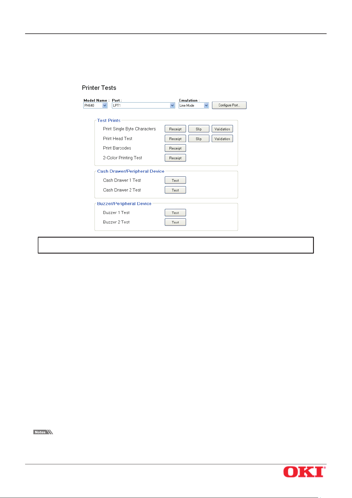
OKIPOS
PH640
5.1.3 Printer Tests
Printer Tests executes the printing function of the printer and prints several samples.
Furthermore, it allows you to conrm that the peripherals work properly.
Software Manual
Important: Printer tests cannot be used for virtual serial ports.
Test Prints
You can check operation of each printer driver (Receipt, Slip, and Validation) by clicking the corresponding
button.
Print Single-Byte Characters
Prints out the single-byte character table.
Print Head Test
If you click Receipt: Tests the thermal printer head by printing several lines of solid black.
If you click Slip or Validation: Tests each of the pins on the dot-impact printer head.
If white vertical lines appear in the black area of the thermal printer head test sample, please clean
the printer head. For information about how to clean the head, refer to the hardware manual.
If the test sample from the dot-impact head shows missing or defective dots, or if cleaning of the
thermal head fails to improve thermal print results, please contact your dealer for assistance.
Print Barcodes
Prints out all supported barcodes.
2-Color Printing Test
Executes 2-color sample printing.
For 2-color printing, conrm that paper for two colors is set.
The printer performs monochrome printing if this type of paper is not set.
Also, refer to “3.5 Selecting the Print Color” for setup.
OKI DATA CORPORATION
- 85 -
Page 89

OKIPOS
PH640
Cash Drawer
Cash Drawer 1 Test
Click the Test button to drive cash drawer 1.
This allows you to conrm that cash drawer 1 works properly.
Cash Drawer 2 Test
Click the Test button to drive cash drawer 2.
This allows you to conrm that cash drawer 2 works properly.
External buzzers
Buzzer 1 Test
Click the Test button to make buzzer 1 sound.
This allows you to conrm that buzzer 1 works properly.
Buzzer 2 Test
Software Manual
Click the Test button to make buzzer 2 sound.
This allows you to conrm that buzzer 2 works properly.
Important: Cash drawers and external buzzers are optional devices.
Note that it is not possible to use buzzers and cash drawers at the same
time.
OKI DATA CORPORATION
- 86 -
Page 90

OKIPOS
PH640
Software Manual
5.1.4 Ethernet I/F Setup
In Ethernet I/F Setup, settings for the Ethernet interface card connected to the printer can be made using
the web browser.
In addition, when using a TCP/IP port with the conguration utility, the TCP/IP port will appear in the Port
list by rst clicking the Search LAN for Printers button.
Click the Search LAN for Printers button to search the printers connected on your LAN.
If there is an applicable printer, the following dialog box will appear. Click the OK button.
OKI DATA CORPORATION
- 87 -
Page 91
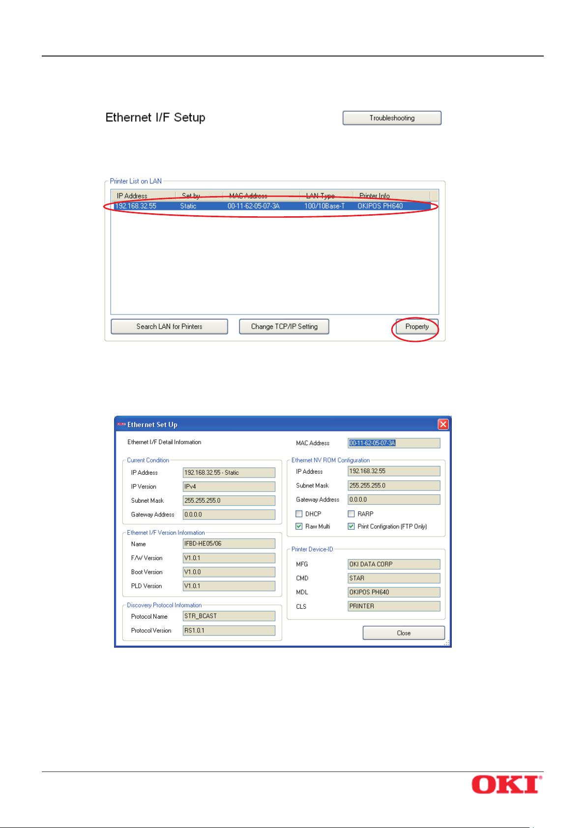
OKIPOS
PH640
All connected LAN printers are shown in the Printer List on LAN.
Software Manual
Select the printer from the Printer List on LAN and click the Property button to display the detailed information of the current Ethernet interface for the selected printer.
If the printers on the LAN cannot be found, click the Troubleshooting button to display “Ethernet I/F Setup
Troubleshooting”.
OKI DATA CORPORATION
- 88 -
Page 92

OKIPOS
PH640
The steps to change the printer TCP/IP settings vary according to whether or not the IP address is assigned
automatically by a DHCP server.
Use the steps according to the environment that you are using.
Software Manual
When IP Address is Automatically Assigned by DHCP Server
1 Select the printer from the Printer List on LAN, and then click the Change TCP/IP Setting button.
2 The utility detects the Ethernet interface card type and displays the corresponding user name and
the default password.
Conrm the settings, and then click the OK button.
OKI DATA CORPORATION
- 89 -
Page 93

OKIPOS
PH640
3 Enter the corresponding user name and the default password displayed in the previous dialog box,
Software Manual
and then click the OK button.
The password can be changed on the web browser.
If the password was changed, enter the new password.
4 The setting dialog box will appear depending on the web browser.
The TCP/IP settings can be performed.
OKI DATA CORPORATION
- 90 -
Page 94

OKIPOS
PH640
When IP Address is Not Assigned by DHCP Server
1 If there are no set IP addresses, you cannot move on to the Change TCP/IP Setting screen.
If a printer was selected that does not have a set IP address, a temporary IP address can be set. Enter
the IP address, and then click the Do ARP and PING button.
Software Manual
2 When the temporary IP address is issued, the following dialog box will appear. Then click the OK but-
ton.
OKI DATA CORPORATION
- 91 -
Page 95

OKIPOS
PH640
3 The utility detects the Ethernet interface card type and displays the corresponding user name and
4 Enter the corresponding user name and the default password displayed in the previous dialog box,
Software Manual
the default password.
Conrm the settings, and then click the OK button.
and then click the OK button.
The password can be changed on the web browser.
If the password was changed, enter the new password.
5 The setting dialog box will appear depending on the web browser.
The TCP/IP settings can be performed.
OKI DATA CORPORATION
- 92 -
Page 96
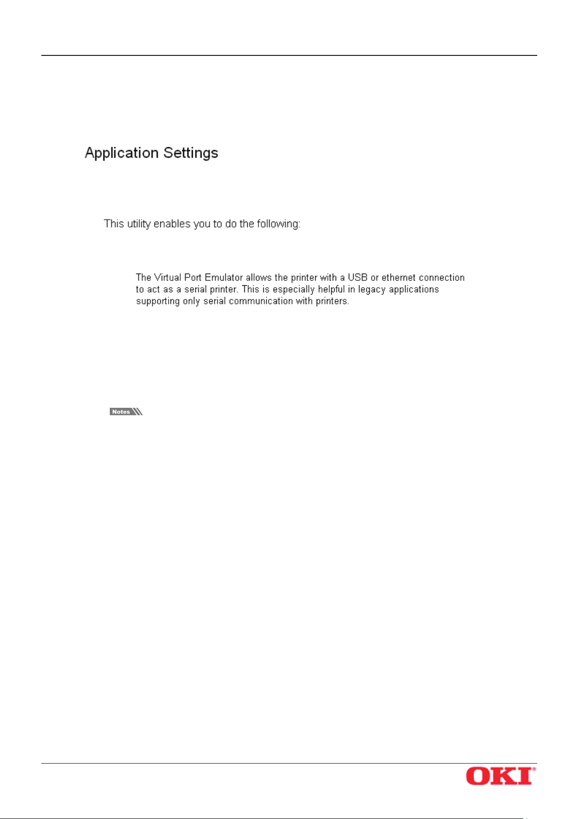
OKIPOS
PH640
5.2 Application Settings
This is for setting each application.
Software Manual
You can set applications for each printer port and printer queue.
OKI DATA CORPORATION
- 93 -
Page 97
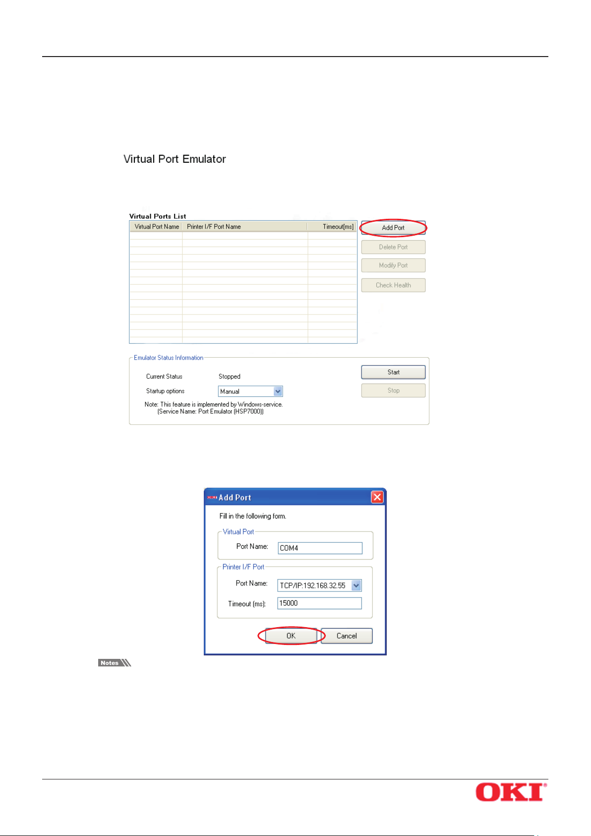
OKIPOS
PH640
Software Manual
5.2.1 Virtual Port Emulator
In Virtual Port Emulator, printers equipped with a USB interface or Ethernet interface can be congured
as virtual serial ports.With this feature, printers equipped with a USB interface or Ethernet interface can be
used with applications that support only serial printers.
Adding a Virtual Port
1 Click the Add Port button to display the following dialog box.
Set all of the items, and then click the OK button.
Enter the output port name of the POS application for the virtual port name.
In addition, for the Port Name of the Printer I/F Port, select the actual printer interface name.
Selection is limited to USB (printer class) and Ethernet ports.
OKI DATA CORPORATION
- 94 -
Page 98
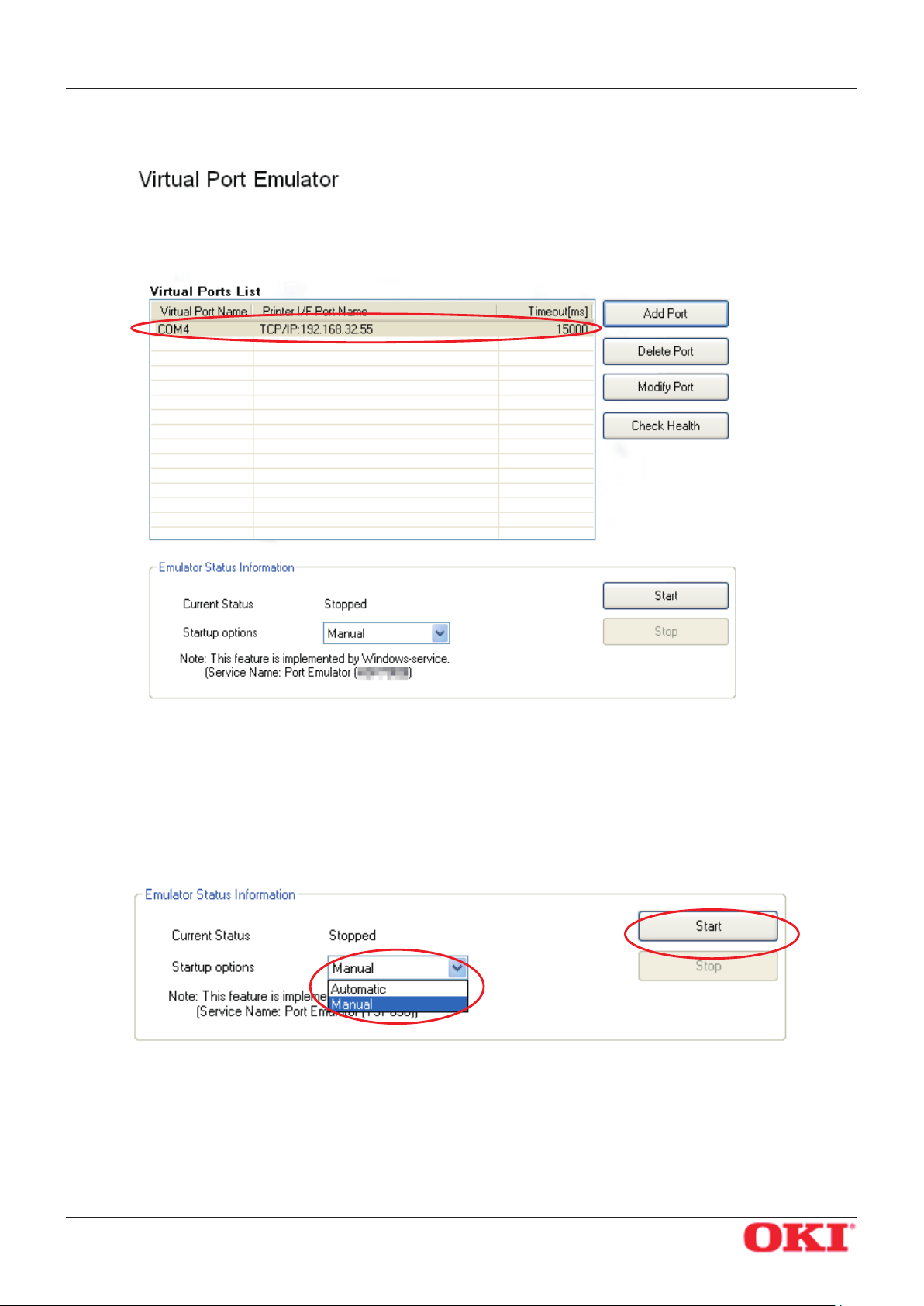
OKIPOS
PH640
2 Created ports are displayed in the Virtual Ports List.
Software Manual
3 Click the Start button to start the emulator function service.
4 Select the timing to start up the emulator function.
When Automatic is selected, this function starts at the same time as the system. This is the most common setting.
When Manual is selected, you must click the Start button manually before using the virtual port
emulator to start the service each time the system starts.
OKI DATA CORPORATION
- 95 -
Page 99
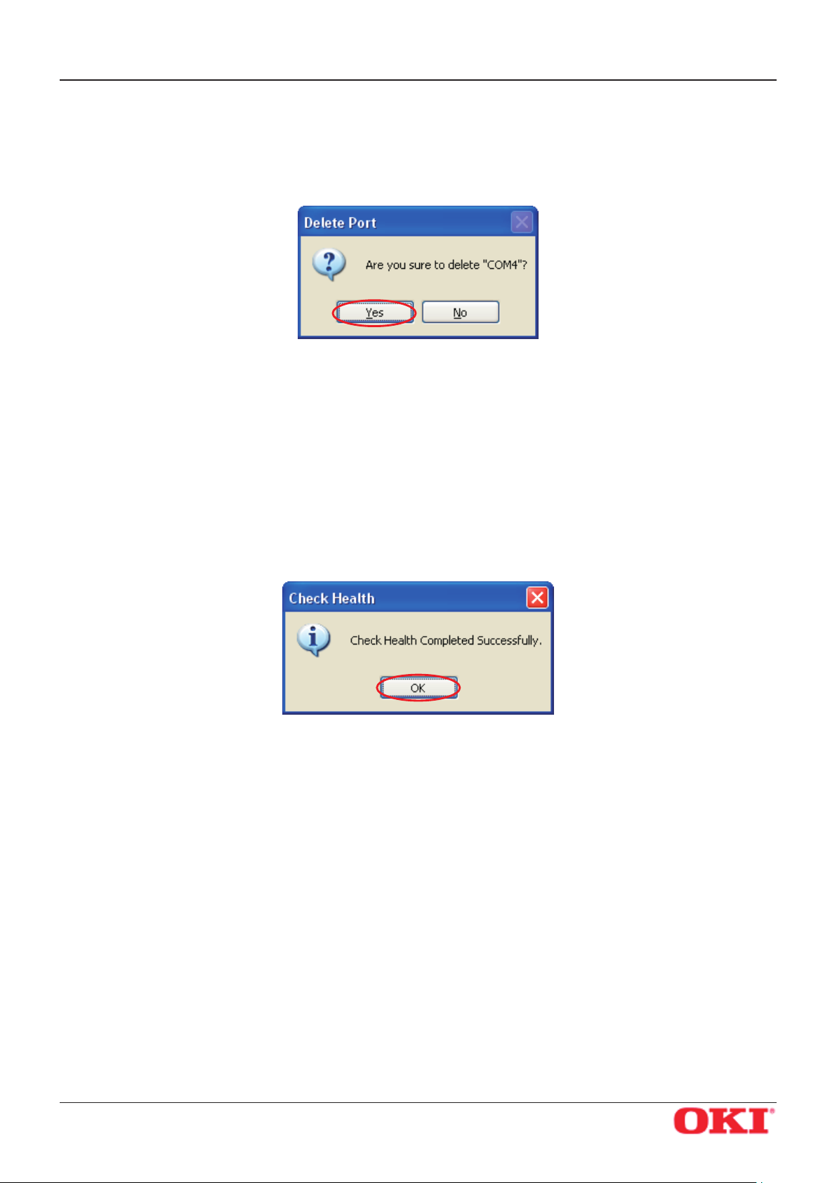
OKIPOS
PH640
Deleting a Virtual Port
1 Select the port to delete from the Virtual Ports List, and then click the Delete Port button.
2 When the following conrmation dialog box appears, click the Yes button to continue.
Modifying a Virtual Port
1 Select the port to modify from the Virtual Ports List, and then click the Modify Port button.
2 The same dialog box as when clicking the Add Port button will appear; therefore, change the set-
tings using the same procedure as when they were rst set.
Software Manual
Check Health
1 Select the port to check from the Virtual Ports List, and then click the Check Health button.
2 If the health check was completed successfully, the following dialog box will appear. Click the OK
button.
OKI DATA CORPORATION
- 96 -
Page 100

OKIPOS
PH640
5.3 Common Data
You can register graphic data that will be used as NV logos.
Software Manual
OKI DATA CORPORATION
- 97 -
 Loading...