

Page 1

OKIPAGE 6e/6ex
LED Page Printer
Maintenance Manual
ODA/OEL/INT
Approval
All specifications are subject to change without notice.
Page 2

PREFACE
This Maintenance Manual describes the field maintenance methods for OKIPAGE 6e and OKIPAGE
6ex LED Page Printers.
This manual is written for use by service persons. Please note that you should refer to the Printer
Handbook for the handling and operating methods of the equipment.
Page 3

CONTENTS
>>>>>
1. CONFIGURATION..................................................................................... 1 - 1
1.1 System Configuration ........................................................................ 1 - 1
1.2 Printer Configuration.......................................................................... 1 - 2
1.3 Optional Configuration....................................................................... 1 - 3
1.4 Specification ...................................................................................... 1 - 5
1.5 Safety Standards ............................................................................... 1 - 7
1.5.1 Certification Label.................................................................................... 1 - 7
1.5.2 Warning Label ......................................................................................... 1 - 8
1.5.3 Warning/Caution Marking ........................................................................ 1 - 9
2. OPERATION DESCRIPTION .................................................................... 2 - 1
2.1 Control Board..................................................................................... 2 - 4
2.2 PS Board ........................................................................................... 2 - 6
2.3 RAM Board ........................................................................................ 2 - 7
2.4 Power Supply Board.......................................................................... 2 - 8
2.5 Electrophotographic Process............................................................. 2 - 10
2.5.1 Electrophotographic Process Mechanism ............................................... 2 - 10
2.5.2 Electrophotographic Process .................................................................. 2 - 13
2.5.3 Process Operation Descriptions .............................................................. 2 - 16
2.6 Paper Jam Detection ......................................................................... 2 - 27
2.7 Cover Open ....................................................................................... 2 - 30
2.8 Toner Low Detection.......................................................................... 2 - 31
3. PARTS REPLACEMENT........................................................................... 3 - 1
3.1 Precautions for Parts Replacement................................................... 3 - 1
3.2 Parts Layout....................................................................................... 3 - 3
3.3 How to Change Parts......................................................................... 3 - 6
3.3.1 Upper Cover ............................................................................................ 3 - 7
3.3.2 Stacker ....................................................................................................3 - 8
3.3.3 LED Head ................................................................................................ 3 - 9
3.3.4 Eject Roller Assy ..................................................................................... 3 - 10
3.3.5 Pulse Motor (Main) .................................................................................. 3 - 11
3.3.6 Pulse Motor (Registration)....................................................................... 3 - 12
3.3.7 Lower Base Unit ...................................................................................... 3 - 13
3.3.8 Motor Assy .............................................................................................. 3 - 14
3.3.9 Hopping Roller Assy ................................................................................ 3 - 15
3.3.10 Stacker Cover Assy ................................................................................. 3 - 16
3.3.11 Registration Roller ................................................................................... 3 - 17
3.3.12 Transfer Roller......................................................................................... 3 - 18
3.3.13 Fusing Unit Assy ..................................................................................... 3 - 19
3.3.14 Back-up Roller ......................................................................................... 3 - 20
3.3.15 Sensor Plate (Inlet).................................................................................. 3 - 21
3.3.16 Toner Sensor (Adhesion) ........................................................................ 3 - 22
3.3.17 Sensor Plate (Outlet) ............................................................................... 3 - 23
3.3.18 Manual Feed Guide Assy ........................................................................ 3 - 24
3.3.19 Sensor Plate (Paper Supply) ................................................................... 3 - 25
3.3.20 Main Control PCB.................................................................................... 3 - 26
3.3.21 Power Supply Board and Contact Assy .................................................. 3 - 27
Page 4

3.3.22 Transformer ............................................................................................. 3 - 28
3.3.23 Cassette Guide L ..................................................................................... 3 - 29
3.3.24 Cassette Guide R .................................................................................... 3 - 30
4. ADJUSTMENT........................................................................................... 4 - 1
4.1 Adjustment......................................................................................... 4 - 1
4.1.1 Maintenance Functions ........................................................................... 4 - 1
4.2 Adjustment......................................................................................... 4 - 10
4.2.1 Maintenance Modes and Functions ........................................................ 4 - 10
4.3 Adjustment When Replacing a Part................................................... 4 - 12
4.3.1 Adjustment at the Time of Part Replacement
(OKIPAGE6e 300dpi LED head) ............................................................. 4 - 12
4.3.2 Adjustment When Replacing a Part (OKIPAGE6ex 600dpi LED head) .. 4 - 14
4.3.3 Uploading / Downloading EEPROM data ................................................ 4 - 17
5. PERIODICAL MAINTENANCE ................................................................. 5 - 1
5.1 Periodical Replacement Parts ........................................................... 5 - 1
5.2 Cleaning............................................................................................. 5 - 1
5.2.1 Cleaning of LED Lens Array .................................................................... 5 - 1
6. TROUBLESHOOTING PROCEDURES .................................................... 6 - 1
6.1 Troubleshooting Tips ......................................................................... 6 - 1
6.2 Check Points before Correcting Image Problems.............................. 6 - 1
6.3 Tips for Correcting Image Problems.................................................. 6 - 1
6.4 Preparation for Troubleshooting ........................................................ 6 - 2
6.5 Troubleshooting Flow ........................................................................ 6 - 3
6.5.1 Status Message/Trouble List ................................................................... 6 - 3
6.5.2 Status Message Troubleshooting ............................................................ 6 - 24
6.5.3 Image Troubleshooting ............................................................................ 6 - 36
7. WIRING DIAGRAM.................................................................................... 7 - 1
7.1 Interconnect Signal Diagram ............................................................. 7 - 1
7.2 PCB Layout and Connector Signal List ............................................. 7 - 3
7.3 Resistance Check.............................................................................. 7 - 15
7.4 Short Plug Setting.............................................................................. 7 - 17
8. PARTS LIST .............................................................................................. 8 - 1
Appendix A Centronics Parallel Interface ................................................. A - 1
B LocalTalk (RS422) Serial Interface........................................ B - 1
C Diagnostics Test..................................................................... C - 1
D Maintenance Utility Overview................................................ D - 1
E Multi-Purpose Feeder Maintenance...................................... E - 1
F High Capacity Second Paper Feeder Maintenance............. F - 1
Page 5

1. CONFIGURATION
Page 6

1. CONFIGURATION
1.1 System Configuration
OKIPAGE 6e and OKIPAGE 6ex consist of control and engine blocks in the standard configuration, as shown in Figure 1-1.
In addition, the options marked with asterisk(*) are available.
Operator Panel
(OKIPAGE 6ex Only)
Paper
Cassette
Engine Unit
* Legal/Universal
Paper Tray
* Hight Capacity
Second Paper Feeder
* Multi-Purpose
Feeder
Paper Feed Mechanism
(First Tray Unit)
Electrophotographic
Processing Unit
Main Control PCB
Face
Down
Stacker
Power Supply
and Sensor PCB
*OKIPAGE 6ex
*OKIPAGE 6e/6ex
Figure 1-1
: PS Board with RAM
: RAM Board
1 - 1
* : Optional
Page 7

1.2 Printer Configuration
The printer unit consists of the following hardware components:
• Electrophotographic Processor
• Paper Feeder
• Main Control PCB
• Operator Panel (OKIPAGE 6ex Only)
• Power Supply Unit
• PS Board (OKIPAGE 6ex Only)
The printer unit configuration is shown in Figure 1-2.
PS Board
Operator panel assy
Fusing unit
Upper cover
Toner cartridge
(consumables)
Stacker cover assy
Image drum unit
(consumable)
Power supply board
Main Control PCB
• L5C or L5D: OKIPAGE6e
• L6A : OKIPAGE 6ex
Figure 1-2
1 - 2
Page 8

1.3 Optional Configuration
The options shown below are available for use with OKIPAGE 6e and OKIPAGE 6ex. These are
available separately from the printer unit.
(1) 1MB Memory Expansion Board (OKIPAGE 6e/6ex)
(2) SIMM Memory
OKIPAGE 6e :1/2/4/8/16 Mbyte
OKIPAGE 6ex :1/2/4/8/16/32 Mbyte
(3) Legal/Universal Paper Cassette/
Legal/Universal cassette
Cassette cover
1 - 3
Page 9

(4) High Capacity Second Paper Feeder
(5) Multi-Purpose Feeder
1 - 4
Page 10

1.4 Specification
(1) Type Desktop
(2) External dimensions Height 6.3” (160 mm)
(excludes protruding Width 12.6” (320 mm)
portion) Depth 14.17” (360 mm)
(3) Weight 8 kg
(4) Developing method Dry electrophotography
Exposing method LED stationary head
(5) Paper used <Type>
• Standard paper
– Xerox 4200 (20 lbs)
• Application paper (manual face-up feed)
– Label
– Envelope
– OHP paper (Transparency)
<Size>
• Standard sizes
– Letter (ODA)
– Legal (option)
– Executive
– Envelope
– A4
– A5
– B5
– A6
• Applicable sizes
– Width: 3.94” to 8.5” (100 to 216 mm)
– Length: 5.83” to 14” (148 to 355.6 mm)
<Thickness>
– Automatic feed: 16 to 24 lbs (60 to 90 g/m2)
– Manual feed: Label, OHP paper (transparency)
Envelope
(6) Printing speed First print: 17 sec.
Continuous print: 6 sheets/min. for letter size paper
Warm-up time: 60 sec. [at room temperature 77˚F
(25˚C) and rated voltage (120 VAC)]
(7) Paper feeding method Automatic feed or manual feed
(8) Paper delivery method Face down/face up
(9) Resolution 300 x 300 dots/inch (OKIPAGE 6e)
600 x 600 dots/inch (OKIPAGE 6ex)
600 x 1200 dots/inch (OKIPAGE 6ex)
1 - 5
Page 11

(10) Power input 120 VAC +5.5%, –15%
230 VAC +15 %, –15%
(11) Power consumption Peak: Approx. 420W
Typical operation: Approx. 160W
Idle: Approx. 55W
Power save mode: Approx. 15W
(12) Temperature and humidity During operation: 50 to 90°F (10 to 32°C)
In storage: 14 to 110°F (–10 to 43°C)
(13) Noise During operation: 48 dB (A) or less
Standby: 38 dB (A) or less
(14) Consumables Toner cartridge kit 2,000 (5% duty)
Image drum cartridge 20,000 (at continuous printing)
15,000 (3 pages/job)
10,000 (1 page/job)
1 - 6
Page 12

1.5 Safety Standards
1.5.1 Certification Label
The safety certification label is affixed to the printer at the location described below.
OKIPAGE 6e OKIPAGE 6ex
OKIPAGE 6e
120V
OKIPAGE 6ex
230V
1 - 7
Page 13

1.5.2 Warning Label
The warning labels are affixed to the sections which may cause bodily injury.
Follow the instructions on warning labels during maintenance.
1 - 8
Page 14

1.5.3 Warning/Caution Marking
The following warning and caution markings are made on the power supply board.
CAUTION
ENGLISH
Heatsink and transformer core present risk of electric shock. Test before touching.
FRENCH
Le dissipateur thermique et le noyau du transformateur présentent des risques de choc
électrique. Testez avant de, manipuler.
SPANISH
Las disipadores de color el núcel del transformador pueden producir un choque eléctrico.
Compruebe antes de tocar.
PORTUGUESE
O dissipador de calor e o núcleo do fransiormador apresentam risco de choque elétrico. Teste
antes de focar.
ENGLISH
Circuits maybe live after fuses open.
FRENCH
Il se peut que les circuits soient sous tension une fois que les fusibles ont éfé rerirés.
SPANISH
Las circuitos pueden estar activos una vez que se hayan abierio los fusibles.
PORTUGUESE
Os circuitos podem estar energizados após os fusiveis se queimarem.
1 - 9
Page 15

2. OPERATION DESCRIPTION
Page 16

2. OPERATION DESCRIPTION
OKIPAGE 6e, OKIPAGE 6ex consists of a Main Control PCB, a power supply/sensor board, a
PostScript board (OKIPAGE 6ex), an operator panel and an electrophotographic process
mechanism.
The soft operator panel is used for operation and status display of OKIPAGE 6e and OKIPAGE
6ex.
The operator panel is used for operation and status display of OKIPAGE 6ex.
The OKIPAGE 6e and OKIPAGE 6ex receive data via the host I/F, these then decode, edit and
store the data in memory. Bit map image data is successively transferred to the LED head in one
dot line units.
OKIPAGE 6e block diagram is shown in Figure 2-1.
OKIPAGE 6ex block diagram is shown in Figure 2-2.
2 - 1
Page 17

1MB Memory Board
(Option)
L5C- or L5D
EEPROM
Centronics
parallel I/F
Reset
circuit
Program & Font
ROM
4MB Mask ROM
7407
16 bits
DATA
BUS
1 Chip CPU
+8V -8V 0V +5V
+30V
For optional
RAM board
L5C
256k x 16 DRAM x 2
CH TR DB
HEAT ON
L5D
Resident RAM
1M x 16 DRAM(2M Bytes)
Resident RAM
(1M Bytes)
Drum motor &
Registration motor
drive circuit
FAN Driver
FAN ALM
High Capacity
Second Paper
Feeder (Option)
M
M
FAN
LED Head
Drum Motor
Registration Motor
Multi-Purpose
Feeder (Option)
Power Supply
Board
Inlet sensor 1
Inlet sensor 2
Paper sensor
Outlet sensor
Paper out sensor
Toner low sensor
Low voltage
generation circuit
AC
transformer
Figure 2-1 OKIPAGE 6e Block Diagram
Cover
open
switch
High voltage
Heater drive
circuit
Filter circuit
generation
circuit
LSI
+5V
Thermistor
Charge roller
Transfer roller
Developing
roller
Toner supply
roller
Cleaning
roller
Heater
AC IN
2 - 2
Page 18

or
1MB Memory Board
LocalTalk I/F (RS422 I/F)
PS Board with RAM
L6A-
EEPROM
Centronics
parallel I/F
Reset
circuit
Program & Font
ROM
4MB Mask ROM
7407
16 bit
32 bit
DATA
BUS
1 Chip CPU
+8V -8V 0V +5V +30V
For optional
RAM board
16 bit
Resident RAM
1M x 16 DRAM
CH TR DB
HEAT ON
(2MB)
Drum motor &
Registration motor
drive circuit
FAN Driver
FAN ALM
High Capacity
Second Paper
Feeder (Option)
M
M
FAN
LED Head
Drum Motor
Registration Motor
Multi-Purpose
Feeder (Option)
Power Supply
Board
Inlet sensor 1
Inlet sensor 2
Paper sensor
Outlet sensor
Paper out sensor
Toner low sensor
Low voltage
generation circuit
AC
transformer
Figure 2-2 OKIPAGE 6ex Block Diagram
Cover
open
switch
High voltage
Heater drive
circuit
Filter circuit
generation
circuit
LSI
+5V
Thermistor
Charge roller
Transfer roller
Developping
roller
Toner supply
roller
Cleaning
roller
Heater
AC IN
2 - 3
Page 19

2.1 Control Board
The control board consists of a single chip CPU, Program & Font ROM's, one or two DRAMs, an
EEPROM, a host interface circuit, and a mechanism driving circuit.
(1) Single chip CPU
The single chip CPU is a custom CPU (32-bit internal bus, 16-bit or 32-bit external bus, 25.54
MHz clock with input frequency from a 12.27 MHz clock) which incorporates the RISC CPU
and its peripheral devices, and has the following functions:
Built-in device Function
Chip select controller Control of ROM, DRAM and I/O device
Bus controller
DRAM controller
DMA controller Transfer of image data from DRAM to video output port
Parallel interface controller Control of Centronics parallel interface
Video output port Control of LED head
LED STB output port
Timer Generation of various control timing
Monitoring of paper running and paper size
Serial I/O port Control of operator panel, EEPROM, and options
I/O port Input and output of sensor and motor signals
(2) Program & Font ROM
OKIPAGE 6e/6ex
The Program & Font ROM store the PCL5e emulation program and various types of fonts.
Mask ROM is used for a Program & Font ROM. The mounting location of this Program & Font
ROM varies depending on the type of ROM (for the mounting location see 7.2).
PS Board
The Program & Font ROM store the PostScript program and various types of fonts. Mask
ROM is used for a Program & Font ROM (for the mounting location see 7.3).
2 - 4
Page 20

(3) DRAM
OKIPAGE 6e/6ex
The DRAM is a resident memory (OKIPAGE 6e: 1MB(L5C) or 2MB(L5D)/OKIPAGE 6ex:
2MB) used as a buffer, and it stores edited data, image data, DLL data and macro data.
OKIPAGE 6ex with PS Board
The DRAM is a resident memory (2MB on the OKIPAGE 6ex main board plus 0.5MB on the
PS board) used as a buffer, and it stores edited data, image data, DLL data and macro data.
In the Post Script emulation, it is used as VM and font cache also.
(4) EEPROM
1,024 bit-Electrically Erasable PROM (EEPROM), is loaded with the following kinds of data:
• Menu data
• Various counter data (Page counter, Drum counter)
• Adjusting parameters (LED head drive time, print start position, paper feed length)
(5) Parallel Interface
Parallel data is received from the host system via parallel interface which conforms to the
Centronics specification. IEEE 1284 Bi-directional parallel is supported.
2 - 5
Page 21

2.2 PS Board (OKIPAGE 6ex option)
The PS board consists of two Program & Font ROM's, DRAM's, an EEPROM, and a host interface
circuit.
(1) Program & Font ROM's
The Program & Font ROMs store the PostScript Level II program and its fonts. Mask ROM
is used for the Program & Font ROMs.
(2) DRAM
0.5MB of DRAM's reside on the PS board.
(3) EEPROM
4.096 bit-Electrically Erasable PROM (EEPROM) is mounted on the PS board for storing the
PostScript's menu settings.
(4) Local Talk I/F
Apple Talk protocol data is received from the host system via LocalTalk interface. The block
diagram is shown in Figure 2-3.
(5) SIMM Socket
LocalTalk I/F
(RS422 I/F)
One SIMM Socket is mounted on the PS board.
Program & Font
ROM
4MB Mask ROM
SCC
85C30
Figure 2-3 PS Board Block Diagram
SIMM
Socket
Resident RAM
(0.5MB)
EEPROM
(4K)
2 - 6
Page 22

2.3 RAM Board (OKIPAGE 6e/6ex option)
The RAM board consists of DRAM's and a SIMM socket.
(1) DRAM
1MB of DRAM's reside on the RAM board.
(2) SIMM Socket
One SIMM socket is mounted on the RAM board.
SIMM Socket
Figure 2-4 RAM Board Block Diagram
Resident RAM
(1MB)
2 - 7
Page 23

2.4 Power Supply Board
The power supply board consists of an AC filter circuit, a low voltage power supply circuit, a high
voltage power supply circuit, heater drive circuit, and photosensors.
(1) Low Voltage Power Supply Circuit
This circuit generates the following voltages.
Output voltage Use
+5 V Logic circuit supply voltage
+30 V Motor and fan drive voltage and source voltage for high-voltage supply
+8 V Analog supply voltage
–8 V PS board and analog circuit supply voltage
(2) High Voltage Power Supply Circuit
This circuit generates following voltages required for electrophotographic process from +5
V, according to the control sequence from the control board. When cover open state is
detected, +5 V supply is interrupted automatically to stop the supply of all high-voltage
outputs.
Output Voltage Use Remarks
CH -1.35 KV Voltage applied to charging roller
DB -300 V/+300 V Voltage applied to developing roller
SB -450 V/ 0 V Voltage applied to toner supply roller
TR +500 V to +4 KV/-750 V Voltage applied to transfer roller Variable
CB +400 V Voltage applied to clearing roller
(3) Photosensor
The photosensor mounted on this power supply board monitors the paper running state
during printing.
2 - 8
Page 24

The sensor layout diagram is shown in Figure 2-3.
Transfer roller
Paper sensor
Toner
sensor
Inlet
sensor 2
Paper
end sensor
Exit roller
Outlet sensor
Heat roller
Inlet sensor 1
Registration roller
Hopping
roller
Paper running direction
Sensor
Inlet sensor 1
Inlet sensor 2
Paper sensor
Outlet sensor
Paper end sensor
Toner low sensor
Figure 2-5
Function
Detects the leading edge of the paper and gives
the supervision timing for switching from
hopping operation to feeding operation.
Monitors paper feeding situation and paper size
based on the paper arrival time and running
time.
Detects the form width.
Detects the leading portion of the paper.
Monitors the paper feeding situation.
Monitors the paper feeding and size according
to the time of arrival to and leaving past the
sensor.
Detects the end of the paper.
Detects the lack of toner.
Sensing state
ON: Paper exists.
OFF: No paper exists.
ON: A4 or larger
OFF: Smaller than A4
ON: Paper exists.
OFF: No paper exists.
ON: Paper exists.
OFF: No paper exists.
ON: Paper exists.
OFF: No paper exists.
- - - - -
2 - 9
Page 25

2.5 Electrophotographic Process
2.5.1 Electrophotographic Process Mechanism
This mechanism actuates the printing of image data supplied by the control board on the paper
by electrophotographic process.
The layout of the electrophotographic process mechanism is shown in Figure 2-6.
2 - 10
Page 26

Eject roller assy
Heat roller
LED head
Charge roller
Developing roller
Image drum unit
Toner cartridge
2 - 11
Figure 2-6
Paper cassette
Outlet sensor lever
Back-up roller
Cleaning roller
Transfer roller
Registration
roller
Inlet sensor lever
Paper sensor lever
Hopping roller
Page 27

(1) Image Drum Unit
The image drum unit consists of a sensitive drum, a charger, and a developer. The unit forms
a toner image on the sensitive drum, using a electrostatic latent image formed by the LED
head.
(2) Registration Motor
The registration motor is a pulse motor of 48 steps/rotation, that is two-phase excited by the
signal from the Main Control PCB. It drives the hopping and registration rollers via two oneway clutches according to the direction of rotation.
(3) Drum Motor
The drum motor is a pulse motor of 48 steps/rotation that is two-phase excited by the signal
from the Main Control PCB and is the main motor of this mechanism.
(4) LED Head
Image data for each dot line from the control board is received by the shift register and latch
register. The 2496 LED's (OKIPAGE 6e)/4992 LED's (OKIPAGE 6ex) are driven to radiate
the image data on the image drum.
(5) Fuser
The fuser consists of a heater, a heat roller, a thermistor and a thermostat.
The AC voltage from the power supply board is applied to the heater controlled by the
HEATON signal from the control board. This AC voltage heats the heater. The Main Control
PCB monitors the heat roller temperature via the thermistor, and regulates the heater roller
to a predetermined temperature (165°C) by connecting or disconnecting the AC voltage
supply to the heater.
When an abnormal rise of the heater roller temperature takes place, the thermostat of the
heater voltage supply circuit becomes active and forcibly cuts the AC voltage supply.
2 - 12
Page 28

2.5.2 Electrophotographic Process
The electrophotographic processing is outlined below. The electrophotographic printing process
is shown in Figure 2-7.
1 Charging
The surface of the image drum is charged uniformly with a negative charge by applying the
negative voltage to the charge roller.
2 Exposure
Light emitted from the LED head irradiates the negatively charged surface of the image drum.
The surface potential of the irradiated portion of the image drum surface becomes lower,
forming the electrostatic latent image associated with the print image.
3 Developing and toner recovery
When the negatively charged toner is brought into contact with the image drum, it is attracted
to the electrostatic latent image by static electricity, making the image visible.
At the same time, the residual toner on the image drum is attracted to the developing roller
by static electricity.
4 Transfer
When paper is placed over the image drum surface, the positive charge which is opposite
in polarity to that of the toner, is applied to the reverse side by the transfer roller. The toner
is attracted by the positive charge and is transferred onto the paper. This results in the
transfer of the toner image formed on the image drum onto the paper.
5 Temporary cleaning
Residual toner which remains on the image drum without being transferred is evened out by
the cleaning roller and is temporarily attracted to the cleaning roller by static electricity.
6 Fusing
The toner image transferred onto the paper is fused to the paper by heat and pressure.
An electrophotographic process timing chart is shown in Figure 2-8.
2 - 13
Page 29

Paper
eject
roller
2 - 14
Figure 2-7
Paper
eject
roller
Paper
eject
(Face up)
Outlet sensor
Heater roller
Paper
path
selector
Fusing
Paper
eject
(Face down)
Power
supply
Charger
roller
Power
supply
Cleaning
roller
Back-up roller
Charging
Cleaning
Power
supply
Image data
LED head
Exposure
Transfer
Transfer
roller
Developing
Paper sensor
Doctor
blade
Developing
roller
Paper
registration
Registration roller
(Bias voltage)
Inlet sensor
Power
supply
Toner
supply
roller
Paper
supply
Hopping
roller
Toner
cartridge
Paper
tray
FusingPaper eject
Cleaning
Transfer
Image
production
developing
Paper feed
Paper hopping
Path of paper
feeding
Direction of
rotation of the
image drum
Page 30

2 - 15
PRINT-N
PRDY-N
DM-ON-N
Figure 2-8
RM-ON
INSNS
OUTSNS-N
Outlet Sensor OFF
Feed stopInlet Sensor OFFFeed start
Page 31

2.5.3 Process Operation Descriptions
(1) Hopping and Feeding
Hopping and feeding motions are actuated by a single registration motor in the mechanism
as shown below:
Registration motor
a
b
Registration gear
Motor gear
Idle gear
Registration roller
Hopping roller
Hopping gear
The registration motor turning in direction "a" drives the hopping roller. The registration motor
turning in direction "b" drives the registration roller. The registration and hopping gears have
one-way bearing, so turning any of these gears in the reverse direction will not transmit the
motion to the corresponding roller.
2 - 16
Page 32

(a) Hopping
1 For hopping, the registration motor turns in direction "a" (CW direction) and
drives the hopping roller to advance the paper until the inlet sensor turns on (in
this case, the registration gear also turns, but the registration roller is prevented
from turning by the one-way bearing).
2 After inlet sensor is turned on by the paper advance, the paper is further
advanced to a predetermined distance until the paper hits the registration roller
(the skew of the paper can thus be corrected).
a
Paper
Registration roller
Hopping roller
2 - 17
Page 33

(b) Feeding
1 When hopping is completed, the registration motor turning in direction "b"
(CCW direction) drives the registration roller to advance the paper (in this case,
the hopping gear also turns, but the hopping roller is prevented from turning by
the one-way bearing).
2 The paper is further advanced, synchronization to the print data.
Image drum
Paper
b
Transfer roller
Hopping
roller
Registration roller
2 - 18
Page 34

(2) Charging
Charging is actuated by the application of the DC voltage to the charge roller that is in contact
with the image drum surface.
Power
supply
Image drum
Charge roller
The charge roller is composed of two layers, a conductive layer and a surface protective
layer, both having elasticity to secure good contact with the image drum. When the DC
voltage applied by the power supply exceeds the threshold value, charging begins. The
applied voltage is proportional to the charge potential, with offset of approximately –550V.
charge potential
[V]
-750
-1300-550 [V]
applied voltage
2 - 19
Page 35

(3) Exposure
Light emitted by the LED head irradiates the image drum surface with a negative charge. The
surface potential of the irradiated portion of the image drum drops, forming an electrostatic
latent image associated with the image signal.
Power
supply
Charge roller
Image drum
LED head
Paper
LED head
Image drum
The image drum is coated with an underlayer (UL), a carrier generation layer (CGL), and
carrier transfer layer (CTL) on aluminum base. The organic photo-conductor layer (OPC),
comprising CTL and CGL, is about 20 µm thick.
2 - 20
Image drum
CTL
CGL
UL
Base
20 µm
30 mm
Page 36

The image roller surface is charged to about –750 V by the contact charge of the charge roller.
When the light from the LED head irradiates the image drum surface, the light energy
generates positive and negative carriers in the CGL. The positive carriers are moved to the
CTL by an electrical field acting on the image drum. Likewise, the negative carriers flow into
the aluminum layer (ground).
The positive carriers moved to the CTL combine with the negative charges on the image drum
surface accumulated by the contact charge of the charge roller, lowering the potential on the
image drum surface. The resultant drop in the potential of the irradiated portion of the image
drum surface forms an electrostatic latent image on it. The irradiated portion of the image
drum surface is kept to about –100 V.
–750
Image drum
surface potential
–100
(V)
0
Charged part
Light
from
LED
Part
irradiated
by
LED
Charged
part
2 - 21
Page 37

(4) Developing
Toner is attracted to the electrostatic latent image on the image drum surface, converting it
into a visible toner image. Developing takes place through the contact between the image
drum and the developing roller.
1 As the toner supply roller rotates while rubbing on the developing roller, a friction
charge is generated between the developing roller and the toner, allowing the toner
to be attracted to the developing roller (the developing roller surface is charged
positive and the toner, negative).
Doctor blade
Charge roller
Toner supply roller
Developing roller
Image drum
2 The toner attracted to the developing roller is scraped off by the doctor blade, forming
a thin coat of toner on the developing roller surface.
3 Toner is attracted to the exposed portion (low-potential part) of the image drum at the
contact of the image drum and the developing roller, making the electrostatic latent
image visible.
–300V
Developing roller
+
–+–+–+–+–+–+–+–+–+–+–+–+–+–+–+–+–+–+–+–+–+–+–
+++++++++++++++++++++++
–750V –100V –750V –750V
Exposed
part
Exposed
part
–100V
Toner
Image drum
An illustration of activities at the contact point of the
image drum surface and the developing roller (arrow
marks denote the direction of the electric field).
2 - 22
Page 38

Note:
The bias voltage required during the developing process is supplied to the toner supply roller and
the developing roller, as shown in the diagram below. –450 VDC is supplied to the toner supply
roller, –300 VDC to the developing roller.
Connected and bias supplied
when the cover
is closed
Image drum
Toner supply roller
Developing roller
Base
2 - 23
Page 39

(5) Transfer
The transfer roller is composed of conductive sponge material, and is designed to get the
image drum surface and the paper in a close contact.
Paper is placed over the image drum surface, and the positive charge, opposite in polarity
to that of the toner, is applied to the paper from the reverse side.
The application of a high positive voltage from the power supply to the transfer roller causes
the positive charge inducement on the transfer roller surface, transferring the charge to the
paper as it contacts the transfer roller. The toner with negative charge is attracted to the
image drum surface, and it is transferred to the upper side of the paper due to the positive
charge on the reverse side of the paper.
Image drum
Transfer roller
Paper
Power
supply
2 - 24
Page 40

(6) Fusing
When the image transfer is completed, the toner image is fused to the paper by heat and
pressure as the paper with unfused toner image passes between the heater roller and the
back-up roller. The heater roller with Teflon coating incorporates a 400W heater (Halogen
lamp), which heats the heat roller.
A thermistor which is in contact with the heater roller regulates the temperature of the heater
roller at a predetermined level (about 165°C). A safety thermostat cuts voltage supply to the
heater off by opening the thermostat in the event of abnormal temperature rises.
The back-up roller is held under a pressure of 3.8 kg applied by the pressure spring on each
side.
Heater roller
Separation claw
Heater
Thermistor
Back-up roller
Pressure spring
2 - 25
Page 41

(7) Cleaning
When the transfer is completed, the residual toner left on the image drum is attracted to the
cleaning roller temporarily by static electricity, and the image drum surface is cleaned.
Image drum
Cleaning roller
Power
supply
Transfer roller
(8) Cleaning of rollers
The charge, transfer and cleaning rollers are cleaned for the following cases:
• Warming up when the power is turned on.
• Warming up after the opening and closing of the cover.
• When the number of sheets accumulated reaches 10 or more, and the printout operation
ends.
• User initiated.
Changes in bias voltage applied to each roller moves the attaching toner off the roller to the
image drum and returns it to the developer.
2 - 26
Page 42

2.6 Paper Jam Detection
The paper jam detection function monitors the paper condition when the power is turned on and
during printing. When any of the following conditions arises, this function interrupts the printing
process. If any of the following errors is encountered, printing can be recovered by removing the
jammed paper (by opening the upper cover, removing the jammed paper and closing the upper
cover).
Error Cause of error
Paper input jam • The paper is in contact with the inlet sensor when the power is turned on.
• After hopping operation is attempted three times, the leading edge of the paper
Paper feed jam • The paper is in contact with at the paper sensor when the power is turned on.
• The leading edge of the paper does not reach the paper sensor within a
• The trailing edge of the paper does not pass over the paper sensor within a
• The leading edge of paper does not reach the outlet sensor within a predeter-
does not reach the inlet sensor.
predetermined distance since the paper has reached the inlet sensor.
predetermined distance after the same has passed over the inlet sensor.
mined distance after the paper has reached the paper sensor.
Paper exit jam • The paper is in contact with the outlet sensor when the power is turned on.
• The paper does not pass over the outlet sensor within a predetermined distance
after the leading edge of the paper has reached the outlet sensor.
• The paper size check for manual feeding finds that the paper size is free size.
Paper size error • The size of the paper is monitored by the inlet sensor 1. The paper is not detected
by the inlet sensor 1 within predetermined distance.
• The inlet sensor 2 detects that the size of the loaded paper is A4 or larger, or
smaller than A4. The detected paper size differs from the paper size set by
command or menu.
• The paper size check for manual feeding finds that the paper size is free size.
2 - 27
Page 43

Drum motor
Registration motor
Paper end sensor
Inlet sensor
Paper sensor
Outlet sensor
Jam Monitor
Top to top
Top to bottom
Top to bottom
Bottom to bottom
Checking for
paper form
Hopping
Monitoring
paper
input jam
Paper
feed
Paper size check
(paper width)
Monitoring
paper feed jam
Paper size check
(Paper length)
Monitoring
paper feed jam
Paper Feed Timing Chart
Paper
feed
Monitoring
paper
feed jam
Monitoring
paper exit jam
2 - 28
Page 44

Paper Feed Check List
Type of error
Paper feed error
Paper feed jam
Paper feed jam
Paper size error
Paper exit jam
Paper feed jam
Note:
Hyphen "-" in the table represent "no check is done."
Monitor
Hopping start
to
Inlet sensor on
Inlet sensor on
to
Write sensor on
Write sensor on
to
Outlet sensor on
Inlet sensor on
to
Inlet sensor off
Outlet sensor on
to
Outlet sensor off
Inlet sensor off
to
Write sensor off
Standard value
72.0
20.0
140.5
Depends on the paper length
Depends on the paper length
22.2
Error
Plus Minus
36.0 _
20.0 _
25.0 _
45.0 45.0
45.0 45.0
22.0 _
Unit : mm
Paper Length List
Check range
Type Paper length
Min. Max.
A4 297.0 252.0 342.0
A5 210.0 165.0 255.0
B5 257.0 212.0 302.0
LETTER 279.4 234.4 324.4
LEGAL 13 330.2 285.2 375.2
LEGAL 14 355.6 310.6 400.6
EXEC 266.7 221.7 311.7
A6 148.0 103.0 193.0
Monarch 190.5 145.5 235.5
COM-9 225.4 180.4 270.4
COM-10 241.3 196.3 286.3
DL 220.0 175.0 265.0
C5 229.0 184.0 274.0
Free 110.0 ~ 355.6 65.0 400.6
Unit : mm
2 - 29
Page 45

2.7 Cover Open
When the stacker cover is opened, the cover open microswitch on the power/sensor board is
turned off to cut +5V supply to the high voltage power supply circuit. This results in the interruption
of all high-voltage outputs. At the same time, the CVOPN signal is sent to the control board to
notify that the microswitch is off, and the control board carries out the cover open process.
2 - 30
Page 46

2.8 Toner Low Detection
• Device
The Toner Low Detection device consists of a stirring gear which rotates at a constant rate,
a stirring bar and a magnet on the stirring bar. The stirring bar rotation is driven by the link
to the protrusion in the stirring gear.
Magnet
Stirring Bar
Stirring Gear
Protrusion
• Operation
Toner Low is detected by monitoring the time interval of the encounter of the magnet set on
the sensor lever and the magnet on the stirring bar.
Stirring Gear Section
Operation during Toner Full state
• The stirring bar is rotated due to the mechani-
Stirring Bar
cal transmission of energy originating from the
interlocking with the stirring gear.
• Even when the magnet on the stirring bar
reaches the maximum height, the stirring bar is
pushed by the stirring gear, since the other end
is being dipped in the toner.
Toner Sensor
Sensor Plate
Operation during Toner Low state
• When the stirring bar reaches the maximum
height, it falls to the minimum height due to its
own weight, since there is no resistance provided by the toner on the other side. Because
of this, the time interval during which it is in
encounter with the magnet of the sensor lever
becomes longer. By monitoring this time interval, Toner Low can be detected.
2 - 31
Stirring Bar
Sensor Plate
Page 47

TONER FULL state
TNRSNS-N
TONER LOW state
TNRSNS-N
• When the Toner Low state is detected 2 times consecutively, Toner Low is established.
• When the Toner Full state is detected 2 times consecutively, Toner Low is cancelled.
4.875 sec.
4.875 sec.
240 ms < t1 < 1.5 sec
t1
t1 > 1.5 sec.
t1
or
t1 < 240 ms
• When there is no change with the toner sensor for 2 cycles (4.875 sec. x 2) or more, then the
Toner Sensor Alarm is activated.
• The toner sensor is not monitored while the drum motor is in halt.
2 - 32
Page 48

3. PARTS REPLACEMENT
Page 49

3. PARTS REPLACEMENT
The section explains the procedures for replacement of parts, assemblies, and units in the field.
Only the disassembly procedures are explained here. For reassembly, reverse the steps of
disassembly procedure.
3.1 Precautions for Parts Replacement
(1) Before starting the parts replacement, remove the AC power cord and interface cable.
(a) Remove the AC power cord in the following sequence:
i) Turn off ("o") the power switch of the printer.
ii) Disconnect the AC inlet plug of the AC power cord from the AC receptacle.
iii) Disconnect the AC power cord and interface cable from the printer.
(b) Reconnect the printer in the following sequence.
i) Connect the AC power cord and interface cable to the printer.
ii) Connect the AC inlet plug to the AC receptacle.
iii) Turn on ("l") the power switch of the printer.
(2) Do not try to disassemble as long as the printer is operating normally.
(3) Do not remove parts which do not need to be touched; try to keep the disassembly to a
minimum.
(4) Use specified service tools.
(5) When disassembling, follow the procedure in sequence laid out in this manual. Parts may be
damaged if these sequences are not followed.
(6) Since screws, collars and other small parts are likely to be lost, they should temporarily be
attached to the original positions during disassembly.
(7) When handling IC's such as microprocessors, ROM's and RAM's, or circuit boards, do not
wear gloves that are likely to generate static electricity.
(8) Do not place printed circuit boards directly on the equipment or floor.
3 - 1
Page 50

[Service Tools]
The tools required for field replacement of printed circuit boards and units are listed in Table 3-1.
Table 3-1 Service Tools
No.
1
2
3
4
5
6
7
8
No. 1-100 Philips
screwdriver
No. 2-100 Philips
screwdriver
No. 3-100 screwdriver
No. 5-200 screwdriver
Digital multimeter
Pliers
Handy cleaner
LED Head cleaner
Q' ty Place of use RemarksService Tools
1
2~2.5 mm screws
1
3~5 mm screws
1
1
1
1
1
1
Cleans LED head
Maintenance Utility
9
(Parts Number:
4YA4046-1722G1)
Adjustment of a
1
printer, etc.
OKIPAGE 6e
OKIPAGE 6ex
3 - 2
Page 51

3.2 Parts Layout
This section describes the layout of main parts of the equipment.
[Lower base unit]
Stacker cover assy
Pulse motor (main)
Eject roller assy
Back-up roller
Lower base
View A
Stacker cover assy
LED head
Diselectrification bar
Transfer roller
Registration roller
Hopping roller
shaft assy
Pulse motor
(registration)
Fusing unit
Toner cartridge
(consumable)
Manual feed
guide assy
Image drum unit
(consumable)
View A
Figure 3-1
3 - 3
Page 52

[Upper cover unit]
Stacker clamp
Stacker
Upper cover
Figure 3-2
3 - 4
Page 53

[Base unit]
DC fan assy
Transformer
RAM board
• LQME-PCB (OKIPAGE 6e/OKIPAGE6ex)
Power supply
Main Control PCB
• L5C or L5D: OKIPAGE 6e
• L6A : OKIPAGE 6ex
Contact assy
Paper cassette
Figure 3-3
3 - 5
Page 54

3.3 How to Change Parts
This section explains how to change parts and assemblies listed in the disassembly diagram
below.
In the parts replacement procedure, those parts marked with the part number inside ● with white
letters are RSPL parts.
Printer unit Upper cover
(3.3.1)
Stacker (3.3.2)
LED head (3.3.3)
Eject roller assy (3.3.4)
Pulse motor (Hopping) (3.3.5)
Pulse motor (Resist) (3.3.6)
Lower base unit
(3.3.7)
Motor assy (3.3.8)
Hopping roller assy (3.3.9)
Stacker cover assy (3.3.10)
Resist roller (3.3.11)
Transfer roller (3.3.12)
Fusing unit assy (3.3.13)
Back-up roller (3.3.14)
Sensor plate (inlet) (3.3.15)
Toner sensor (3.3.16)
Sensor plate (outlet) (3.3.17)
3 - 6
Manual feed guide assy (3.3.18)
Sensor plate (Paper supply) (3.3.19)
Main control PCB (3.3.20)
Power supply board and contact assy (3.3.21)
Transformer (3.3.22)
Cassette guide L (3.3.23)
Cassette guide R (3.3.24)
Page 55

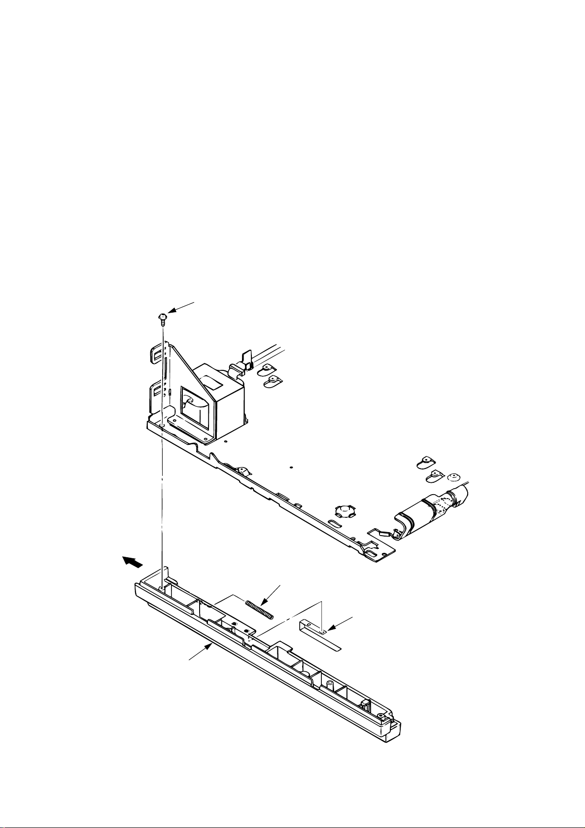
3.3.1 Upper Cover
(1) With the power switch turned off, unplug the AC power cord from the outlet.
(2) Disconnect the interface cable 1.
(3) Remove the option board D if it is mounted.
(4) Lift the left side of the operator panel assy (or logo frame) 4 and remove it.
(5) Disconnect the flexible cable 5 from the connector (CN1) 6 of the operator panel PCB 6,
and put the cable inside the cover. (OKIPAGE 6ex only)
(6) Open the stacker cover assy 9 by pressing the knobs 8 on the left and right sides.
(7) Remove the image drum unit 0.
(8) Remove two screws A, and open the manual feed guide assy B. Lift the front of the upper
cover C up and release the claws at two locations on the back side. Align the stacker cover
9 against the diagonal line of the square holes of the upper cover and lift up the upper cover
C slightly, then remove it.
Note:
When removing or installing the upper cover, be careful not to damage the cable 5.
5
6
4
A
A
C
1
D
9
8
=
8
B
3 - 7
Page 56

3.3.2 Stacker
(1) Remove the upper cover. (See 3.3.1)
(2) Remove two stacker clamps 1 and the stacker 2 by bending the upper cover.
1
1
2
3 - 8
Page 57

3.3.3 LED Head
(1) Open the stacker cover.
(2) Remove the flexible cable (LED) 1 from the PC connector 2 of the LED head 3.
(3) Remove the LED head by prying the left side free from the retaining clip.
Note:
Be careful to not lose the contact (LED) 4.
Note:
• Be sure not to directly touch or push the SLA part of the LED head.
• After mounting the new LED head, set drive time of the LED head according to the
marking on the LED head (see 4.3.1 or 4.3.2).
• For the installation of the flexible cable (LED) 1, install the PC connector 2 to the
flexible cable (LED) 1 first, then connect the LED head 3 to the PC connector.
• When installing a new LED head, be careful not to lose the contact (LED) 4.
OKIPAGE 6e
SLA part
2
1
OKIPAGE 6ex
4
3
1
2
3
3
3 - 9
Page 58

3.3.4 Eject Roller Assy
(1) Remove the upper cover (see 3.3.1).
(2) Press the clamp on the left side of the eject roller assy 1 in the direction of the arrow. Detach
the eject roller assy from the lower base unit 2, and remove it.
Note:
When installing the eject roller, verify the proper engagement with the main unit.
1
2
3 - 10
Page 59

3.3.5 Pulse Motor (Main)
(1) Remove the upper cover (see 3.3.1).
(2) Remove the connector 3 from (CN2) 2 of the Main Control PCB 1.
(3) Remove two screws 4 and remove the pulse motor (main) 6 from the motor bracket 5.
1
2
CN2
OKIPAGE 6ex OKIPAGE 6e
5
CN2
3
4
View A
6
4
3 - 11
Page 60

3.3.6 Pulse Motor (Registration)
(1) Remove the upper cover (see 3.3.1).
(2) Remove the connector 3 from (CN3) 2 of the Main Control PCB 1.
(3) Remove two screws 4 and remove the pulse motor (registration) 6 from the motor bracket
5.
OKIPAGE 6e
CN3
OKIPAGE 6ex
1
2
CN3
3
5
4
6
View A
4
3 - 12
Page 61

3.3.7 Lower Base Unit
(1) Remove the upper cover (see 3.3.1).
(2) Remove the connecting cables 4 and 5 of the pulse motor from the connectors 2 and 3
of the Main Control PCB 1.
(3) Remove the connector 6 of the LED head from the Main Control PCB 1.
(OKIPAGE 6e: 1 connector, OKIPAGE 6ex: 2 connectors)
(4) Remove seven screws 7, then remove the lower base unit 8.
7
7
7
7
3
2
4
8
6
5
1
3 - 13
Page 62

3.3.8 Motor Assy
(1) Remove the upper cover (see 3.3.1).
(2) Remove the lower base unit (see 3.3.7).
(3) Stand the lower base unit on its side as shown, and unlock two clamp levers, then remove
the motor assy 1.
1
Idle gear
Idle gear
Reduction gear
Clamp lever
3 - 14
Page 63

3.3.9 Hopping Roller Assy
(1) Remove the upper cover (see 3.3.1).
(2) Remove the lower base unit (see 3.3.7).
(3) Remove the motor assy (see 3.3.8).
(4) With the lower base unit 1 standing on its side, remove the one-way clutch gear 2 and the
bearing (A) 3, then remove the hopping roller assy 4 and the bearing (B) 5.
1
2
3
3 - 15
4
5
Page 64

3.3.10 Stacker Cover Assy
(1) Remove the upper cover (see 3.3.1).
(2) Remove the motor assy (see 3.3.8).
(3) Remove the reset lever R 1.
(4) Detach the reset spring 2 from the lower base unit 3, turn the reset level L 4 in the direction
of the arrow A until it stops, and remove it in the direction of the arrow B.
(5) Release two pins of the lower base unit 3, then remove the stacker cover assy 5.
5
2
A
1
3
A
C
B
4
3 - 16
Page 65

3.3.11 Registration Roller
(1) Remove the upper cover (see 3.3.1).
(2) Remove the lower base unit (see 3.3.7).
(3) Remove the motor assy (see 3.3.8).
(4) With the lower base unit standing on its side (view A), remove the one-way clutch gear 1.
(5) Press the registration roller 2 to the right side (in the direction of the arrow as shown) and
lift up the left side. Remove the registration roller 2 and the bearing (registration) 3.
1
2
3
View A
View A
3 - 17
Page 66

3.3.12 Transfer Roller
(1) With the power switch turned off, unplug the AC power cord from the outlet.
(2) Open the stacker cover.
(3) Release TR gear 1 by unlocking the latch 4 of the main unit (never apply an excessive force
when unlocking the latch).
(4) Lift the right side of the transfer roller 2, and shift it to the right side, then pull it out from the
main unit (at this time, the bearings 3 of the left and right sides of the transfer roller 2 will
release themselves).
3
2
3
1
1
4
latch
3 - 18
Page 67

3.3.13 Fusing Unit Assy
(1) Remove the upper cover (see 3.3.1).
(2) Remove the lower base unit (see 3.3.7).
(3) Remove the stacker cover assy (see 3.3.10).
(4) Remove four screws 1 and remove the fusing unit 2.
Caution:
Note:
Fusing unit assy may be hot. Use care when handling.
When installing or removing the fusing unit assy, tighten or loosen the screws while
holding the fusing unit down with your hand.
1
2
3 - 19
Page 68

3.3.14 Back-up Roller
(1) Remove the fusing unit assy (see 3.3.13).
(2) Lift the left side of the back-up roller 1, and pull it out to the left side (at this time, two bushings
2, the bias springs 3 and washers 4 and 5 will release themselves).
3
Note:
2
5
Do not bend or lose springs.
1
2
3
4
3 - 20
Page 69

3.3.15 Sensor Plate (Inlet)
(1) Remove the upper cover (see 3.3.1).
(2) Remove the lower base unit (see 3.3.7).
(3) Press the clamps of three sensor plates (inlet) 1, and remove the sensor plates by pressing
them upward from the bottom side.
1
Inlet sensor 2
1
Paper sensor
Inlet sensor 1
Clamp
Clamp
3 - 21
Page 70

3.3.16 Toner Sensor (Adhesion)
(1) Remove the upper cover (see 3.3.1).
(2) Remove the lower base unit (see 3.3.7).
(3) Press the clamp of the toner sensor 1, and remove the sensor by pushing it up from the
bottom.
1
Clamp
Clamp
1
3 - 22
Page 71

3.3.17 Sensor Plate (Outlet)
(1) Remove the upper cover (see 3.3.1).
(2) Remove the eject roller assy (see 3.3.4).
(3) Remove the lower base unit (see 3.3.7).
(4) Remove the fusing unit assy (see 3.3.13).
(5) Press the clamp of the sensor plates (outlet) 1, and remove the sensor plate by pushing it
up from the bottom.
1
Clamp
Clamp
1
3 - 23
Page 72

3.3.18 Manual Feed Guide Assy
(1) Remove the upper cover (see 3.3.1).
(2) Open the manual feed guide assy 1, and release the engagement on both sides with the
main unit by carefully bending the manual feed guide assy 1.
Note:
At the time of mounting, verify the proper the engagements as shown in the diagram.
Put into the post.
Put into the groove.
3 - 24
1
Page 73

3.3.19 Sensor Plate (Paper Supply)
(1) Remove the upper cover (see 3.3.1).
(2) Remove the lower base unit (see 3.3.7).
(3) Press the clamp of the sensor plate (paper supply) 1, and remove it from the base plate 2.
1
View A
1
View A
2
3 - 25
Page 74

3.3.20 Main Control PCB
Note:
When replacing the Main Control PCB, the contents of the EEPROM shall be copied to the
new PCB. This process requires a maintenance utility. (See 4.3.1 4 and 4.3.2 4 for
details.)
• The Main Control PCB is different for each model.
OKIPAGE 6e : L5C or L5D
OKIPAGE 6ex : L6A
(1) Remove the upper cover (see 3.3.1).
(2) Remove the lower base unit (see 3.3.8).
(3) Remove two screws 1.
(4) Move the Main Control PCB 2 in the direction of arrow A to disconnect it from the power
supply board 3.
(5) Remove the Main Control PCB 2 together with the PCB guide plate 4 (disconnect the fan
motor connector 5 from the Main Control PCB).
(6) Remove three screws 6 and remove the PCB guide plate 4 from the Main Control PCB 2.
Do not bend or lose ground plate 9.
6
6
1
5
9
1
CN1
CN3
4
2
A
CN7
6
3
3 - 26
Page 75

3.3.21 Power Supply Board and Contact Assy
(1) Remove the upper cover (see 3.3.1).
(2) Remove the lower base unit (see 3.3.7).
(3) Remove the Main Control PCB (see 3.3.20).
(4) Remove the AC inlet 1 from the inlet holder 2, and remove the connector 3 of the
transformer.
(5) Remove the screws 4, and remove the ground cable 5.
(6) Remove three screws 6, and remove the power supply board 7 and contact assy 8 at the
same time.
(7) Unlock two claws 9, and remove the contact assy 8 from the power supply board 7.
Note:
When mounting the lower base unit, be careful about the paper end sensor.
Do not apply excessive force to the power switch during reassembly.
6
3
1
3
6
8
View A
8
9
9
View A
6
7
4
5
2
3 - 27
Page 76

3.3.22 Transformer
(1) Remove the upper cover (see 3.3.1).
(2) Remove the lower base unit (see 3.3.7).
(3) Remove the connectors (CN1 and CN2).
(4) Remove the inlet 3 from the inlet holder 2.
(5) Remove two screws 1, and remove the inlet holder 2 and the transformer 4.
1
1
2
3
4
3 - 28
Page 77
3.3.23 Cassette Guide L
(1) Remove the paper cassette.
(2) Remove the upper cover (see 3.3.1).
(3) Remove the lower base unit (see 3.3.7).
(4) Remove the Main Control PCB (see 3.3.20).
(5) Remove the power supply board (see 3.3.21).
(6) Remove the screw 1, and remove the cassette guide L 2 by shifting it in the direction of the
arrow.
(7) Detach the eject spring 3, and remove the support spring 4 from the cassette guide L 2.
1
2
3
4
3 - 29
Page 78

3.3.24 Cassette Guide R
(1) Remove the paper cassette.
(2) Remove the upper cover (see 3.3.1).
(3) Remove the lower base unit (see 3.3.7).
(4) Remove the Main Control PCB (see 3.3.20).
(5) Remove the screw 1, and remove the cassette guide R 2 by shifting it in the direction of
the arrow.
(6) Pull the eject spring 3 out of the cassette guide R 2, then remove the support spring 4.
1
4
2
3
3 - 30
Page 79

4. ADJUSTMENT
Page 80

4. ADJUSTMENT
4.1 Adjustment (OKIPAGE 6e)
This chapter describes the adjustment necessary when replacing a part. The adjustment is made
by changing the parameter value set in EEPROM on the Main Control PCB by means of a printer
driver or by a maintenance utility program.
The maintenance utility is designed to be used only by field engineer and it should not be released
to the end-users.
4.1.1 Maintenance Functions
1 Printer driver
Printer driver has following functions
• Drum counter reset
• Printer menu default
• Charge roller cleaning
Figure 4-1
(a) Drum counter reset
For initializing engine counter when user has replaced an Image drum unit.
The counter is reset by clicking "Drum Count Reset" button.
(b) Printer menu default
For resetting the printer menu to the default value.
The menu is automatically reset by clicking "Menu Reset" button.
(c) Charge roller cleaning
For cleaning a charge roller of the Image drum unit.
It is used when print quality is deteriorated.
For details, refer to the user's manual.
4 - 1
Page 81

2 Maintenance utility
Maintenance utility has following functions.
(1) Engine Menu
For setting the engine menu.
(2) Engine Counter Reset
For resetting the engine counter.
(3) Status Monitor
For real time display of the printer status.
(4) Test print
For local print or test print.
(5) Reload
For reading out the printer setting information.
(6) Option
Other functions.
Fig. 4-2 shows the Main Menu Dialog.
Figure 4-2
4 - 2
Page 82

2-1 Engine Menu
The following functions can be set in the Engine Menu.
(1) Print Position
For adjusting print start position.
(2) LED Head Marking No.
For adjusting LED Head marking duration.
(3) LED Head Width
For stipulating number of LED dots.
(4) Optical head
The mounting head type is set.
(5) Head type
The adjustment method for the adjustment head for 600 DPI is set.
(6) Page PRT
Valid or invalid of page count print of menu print is set.
(7) Wait table
The standby temperature 150°C or 135°C is set.
(8) Setting
For adjusting transfer current value.
(9) Enter
For entering the value newly set by the menu.
(10)Cancel
For canceling the value not yet entered.
4 - 3
Page 83

2-2 Engine Counter
The following functions can be set in the Engine Counter.
Each item is reset by clicking of the "Reset" button.
(1) Drum Count
The number of drum revolution of the EP drum unit, counted at the engine block.
(2) Total Drum Count
The total number of drum revolution of the printer, counted at the engine block.
(3) Page Count
The total number of printed pages counted at the engine block.
(4) Reset All
Resetting all counters by clicking of the button.
2-3 Status Monitor
The Status Monitor checks printer status for real time display.
2-4 Test Print Button
The Test Print Button shows the Test Print Dialog to execute local print or test file print.
(1) Print Menu
It performs the menu print.
(2) Print Demo
It performs a demo print.
(3) Print Fonts
It prints font samples.
(4) Cleaning
It performs special print to clean the charge roller.
4 - 4
Page 84

(5) Print File
It performs a test file print.
Printer emulation is stipulated by a file suffix.
xxx.HBP (Hiper-W emulation)
xxx.BIN (PCL emulation)
xxx.PRN (Ditto)
xxx.aaa (Ditto: aaa may be any strings other than the above.)
Figure 4-3
2-5 Option Menu Button
It performs operation selected in the Option Button Menu.
Available operations are as follows.
(1) Reset Engine
It resets all the Engine Menu contents to the factory default setting.
(2) EEPROM Upload
It upload the contents of the Engine Menu Setting and Engine Counter data into the
memory on the PC.
(3) EEPROM Download
It download the Engine Menu Setting and Engine Counter data from the memory on
the PC and copy it to the EEPROM on the printer.
4 - 5
Page 85

(4) Product set
Product (ID) of the printer is set. Product which is available at present is only MDL
(Model). Up to 32 alphanumeric characters can be inputted.
The corresponding type is the type supporting the ID down- load command. For an
unsupported type, no character can be inputted as light color display.
(5) Printer name set
The corresponding type is changed.
Figure 4-4
4 - 6
Page 86

2-6 Correspondence to non-corresponding product ID printer
When the ID of the printer is not corresponding, a dialog for selecting the corresponding
printer name is displayed. When the printer name is set, it is registered in the initialization
file and processed as a corresponding printer also for the next and subsequent startup.
The following is a display example of a printer set dialog.
Figure 4-5
The following five types of printer names can be set.
OKIPAGE 4w
OL400w or OL410e/W
OL600e or OL600e/W
OL610e or OL610e/W
OKIPAGE 4w Plus
OKIPAGE 6ex or OKIPAGE 6e
4 - 7
Page 87

2-7 Reload Button
The same setting as in the starting up of an application software can be made. It reads out
the settings of the printer being connected.
It is used to change the printer while running the same application program on the PC.
2-8 About Button
It displays information on the Maintenance Utility and the printer firmware.
2-9 Exit Button
It ends the Maintenance Utility.
Figure 4-6
4 - 8
Page 88

2-10 Setup Dialog
The Setup Dialog is displayed when "Setup" is selected from the system menu items on
the Main Menu Dialog.
In the Setup Dialog, selection of printer languages and printer port is available.
Figure 4-7
(1) Printer Port
For selecting a printer port.
(2) Cancel
For canceling the setting and returning to the Main Menu Dialog.
(3) OK
For initializing the settings to reflect all the settings in the menu.
4 - 9
Page 89

4.2 Adjustment (OKIPAGE 6ex)
This chapter describes the adjustment necessary when replacing a part. The adjustment is made
by changing the parameter value set in EEPROM on the Main Control PCB. The parameter can
be set by the key operation from the operator panel. This printer has three kinds of maintenance
modes, and it is necessary to select one of the modes when replacing a part.
4.2.1 Maintenance Modes and Functions
1 User Maintenance Mode
This mode is being released to end-users, but it is rarely accessed.
To enter into the user maintenance mode, turn the POWER switch on while holding the
MENU key down.
Function
There are following five functions:
• Hex dump • Drum counter reset
• Menu reset • Operator panel menu disable
• X-adjust / Y-adjust
Detailed descriptions of these functions are provided in Appendix C, DIAGNOSTICS
TEST.
2 System Maintenance Mode
Note:
To enter into the system maintenance mode, turn the POWER switch on while holding the
RECOVER key down.
Function
There are following five functions:
• Page count display
• Page count printing enable/disable • EEPROM reset
• Rolling ASCII continuous printing
• HIPER-W ENABLE/DISABLE
• SIDM ENABLE/DISABLE
This mode is used only by service persons and it should not be released to the endusers.
Detailed descriptions of these functions are provided in Appendix C, DIAGNOSTICS
TEST.
4 - 10
Page 90

3 Engine Maintenance Mode
Note:
To enter into the engine maintenance mode, turn the POWER switch on while holding the
FORM FEED and ENTER keys down.
Function
There are following functions :
• Head drive time setting • Drum count total display
• Printing start position setting • Engine reset
• Drum count display • Factory adjustment
• LED head width setting • LED head type setting
• Transfer current setting • Optical LED head (Mounting head type)
• Setting of strobe time
• Selection of standby temperature
• Engine test
This mode is used only by service persons, and it should not be released to the end
users.
(Adjustment method for adjustment head)
Note:
Detailed descriptions of these functions are provided in Appendix C, DIAGNOSTICS
TEST.
"Printing start position setting" is for shipping. Do not change its default value.
4 - 11
Page 91

4.3 Adjustment When Replacing a Part
4.3.1 Adjustment at the Time of Part Replacement (OKIPAGE6e: 300dpi LED head)
The following table lists parts that require adjustment after replacement.
Parts
LED head
Image drum unit Drum counter reset (Refer to the user's manual for details.)
Control P.C.B. Upload/Download EEPROM data
LED head drive time
Required Adjustment
1 LED head drive time setting
Caution:
Do not change the LED head drive time when the luminous energy indicated on
the new LED head is the same as that of the old LED head.
The LED head drive time is set in the LED Head Marking No. on the Engine Menu of the
Maintenance Utility. Input the value printed on the serial No. label on the LED head. The
last 3 digits indicates the luminous energy of the LED head. (See Fig. 4-2.)
• LED head luminous energy
4 - 12
The last 3 digits indicates the
luminous energy of the LED head.
Luminous energy indications
070
|
314
Page 92

OKIPAGE6e
• Setting of LED Head Drive Time
Drive time of the LED head is set by setting the parameter of drive time of EEPROM
according to the luminous intensity marking on the LED head.
a. Corresponding table of luminous intensity marking and drive time parameter
Luminous intensity
marking on LED head
056 ~ 062 34
063 ~ 065 33
066 ~ 069 32
070 ~ 076 31
077 ~ 082 30
083 ~ 088 29
089 ~ 096 28
097 ~ 104 27
105 ~ 112 26
113 ~ 121 25
122 ~ 131 24
Drive time parameter
Luminous intensity
marking on LED head
132 ~ 142 23
143 ~ 154 22
155 ~ 167 21
168 ~ 180 20
181 ~ 195 19
196 ~ 211 18
212 ~ 228 17
229 ~ 247 16
248 ~ 268 15
269 ~ 290 14
291 ~ 313 13
Drive time parameter
4 - 13
Page 93

4.3.2 Adjustment When Replacing a Part (OKIPAGE6ex: 600dpi LED head)
Adjustment is necessary when replacing any one of the following parts.
Parts
LED head
Image drum unit Drum counter reset (Refer to the User's Manual.)
Main Control Board EEPROM data Upload/Download (See 4.3.1 4.)
1 Setting of LED Head Drive Time
Note:
• Luminous Intensity Marking Label
When the luminous intensity marking of the replacement LED head (new part) is
same as that of the removed LED head (old part), do not set the LED head drive
time.
LED head drive time
Head Type
Required Adjustment
401326
403579
1224G2
7 3
or
. . . . .
73000123400101100
or
. . . . .
74000123400101100
4 - 14
Last 3 digits represent the
LED head marking number.
Luminous intensity marking
027
|
154
Page 94

OKIPAGE6ex
• Setting of LED Head Drive Time
Drive time of the LED head is set by setting the parameter of drive time of EEPROM
according to the luminous intensity marking on the LED head.
a. Corresponding table of luminous intensity marking and drive time parameter
Luminous intensity
marking on LED head
027 ~ 028 27
029 ~ 030 26
031 ~ 032 25
033 ~ 035 24
036 ~ 037 23
038 ~ 040 22
041 ~ 043 21
044 ~ 046 20
047 ~ 049 19
050 ~ 052 18
053 ~ 057 17
058 ~ 060 16
061 ~ 064 15
Drive time parameter
Luminous intensity
marking on LED head
065 ~ 069 14
070 ~ 073 13
074 ~ 079 12
080 ~ 084 11
085 ~ 090 10
091 ~ 096 9
097 ~ 103 8
104 ~ 110 7
111 ~ 118 6
119 ~ 126 5
127 ~ 135 4
136 ~ 144 3
145 ~ 154 2
Drive time parameter
4 - 15
Page 95

Setting
Example:
Method for setting the parameter to 19 (for case where the previous
parameter setting was 8).
Operation
Turn the POWER switch
on while holding the
FORM FEED and ENTER
keys down.
Press the MENU key.
Press + or - key, until "19"
is displayed.
Press the ENTER key.
LCD display after operation
ENG MNT
OPT HEAD
600-4W
LED HEAD
No. 8 *
LED HEAD
No. 19
The item of “OPT HEAD” is
always 600-4W when the
600dpi head is used.
Displays previous
parameter No.
Turn the POWER switch on
while pressing the FORM
FEED and ENTER keys.
XXX: HP4, AUT, WIN or HEX DUMP
LED HEAD
No. 19 *
HEAD TYPE
TYPE1
ON-LINE
XXX
Parameter 19 is
set to EEPROM
(* is displayed on
LCD).
There are two types of “HEAD TYPE”
available (TYPE-1, TYPE2D4).
The type is set as shown below
according to the content of the
bar code label attached on the head.
Content of the bar code label on the head
xxxxxx
. . . . .
73000123400101100
When the numeral of upper two digits
under the bar code is 73, TYPE 1 is selected.
When the numeral of upper two digits
under the bar code is 74, TYPE2D4 is selected.
4 - 16
Page 96

4.3.3 Uploading/Downloading EEPROM data
When the controller printed circuit board is replaced, the contents of the old EEPROM shall
be copied to the new EEPROM on the new board to preserve customer settings. For the
purpose, use the EEPROM operation on the Option of the Maintenance Utility. (See Fig.
4-4.) To copy follow the steps below.
(1) Be sure to confirm that the printer and the PC are connected with a centronics I/F cable.
Then execute the Maintenance Utility. (Note: Printer driver shall be deinstalled.)
(2) Select the Option on the Maintenance Utility.
(3) Click the "UPLOAD EEPROM" button on the "EEPROM Operations".
(4) The contents of the EEPROM data is displayed on the "DIALOG" of the Maintenance
Utility. The contents of the old EEPROM is now copied into the memory of the PC.
(5) Replace the controller P.C.B. with a new one while it displays the above "DIALOG".
(6) After the replacement, click "Download EEPROM" on the "EEPROM Operations".
EEPROM upload has been completed.
In case of troubles such as centronics I/F failure, etc. EEPROM data may not be uploaded
properly. In such case, it is necessary to adjust the following setitngs manually after the
replacement using the Maintenance Utility.
• LED driver time (See 4.3.1.)
• Factory setting (ODA/OEL/INT-A/INT-L)
4 - 17
Page 97

5. PERIODICAL MAINTENANCE
Page 98

5. PERIODICAL MAINTENANCE
5.1 Periodical Replacement Parts
The parts are to be replaced periodically as specified below:
Part name Condition for replacement Cleaning Remarks
• Toner cartridge About 2,000 sheets of • LED head. Consumables
paper have been printed.
• Image drum About 20,000 sheets of Consumables
cartridge paper have been printed.
5.2 Cleaning
Remove any toner or dust accumulated inside the printer. Clean in and around the printer with
a piece of cloth when necessary. Use the handy cleaner (vacuum) to clean inside the printer.
Note:
Do not touch the image drum, LED lens array, or LED head connector block.
5.2.1 Cleaning of LED Lens Array
Clean the LED lens array or replace the toner cartridge when white lines or stripes (void, light
printing) are generated vertically down the page.
Note:
The LED lens array must be cleaned with an LED head cleaner, provided with each toner
kit.
White lines or stripes
(void, light printing)
5 - 1
Page 99

(1) Set the LED head cleaner to the LED lens array as shown in the figure, then slide the cleaner
back and forth horizontally several times to clean the head.
Note:
Gently press the LED head cleaner onto the LED lens array.
LED head cleaner
LED lens array
(2) Throw the cleaner away.
5 - 2
Page 100

6. TROUBLESHOOTING PROCEDURES
 Loading...