

Page 1

OKIPAGE 12i PAGE PRINTER
10 Base-T Ethernet network adapter card
User's Guide
© 1998 OKI DATA CORPORATION
Page 2

Every effort has been made to ensure that the information in this document
is complete, accurate, and up-to-date.
OKIDATA assumes no responsibility for the results of errors beyond its
control. OKIDATA also cannot guarantee that changes in software and
equipment made by other manufacturers and referred to in this guide will
not affect the applicability of hte information in it. Mention of software
products manufactured by other companies does not necessarity constitute
endorsement by OKIDATA.
Copyright 1998 by OKIDATA. All rights reserved.
First Edition February , 1998
OKIDATA ,OKILAN and OkiView are registered trademarks of Oki Erectric
Industry Company , Ltd.
OKIDATA: Marque déposée de Oki Elecric Industry
Company , Ltd.; Marca Registrada, Oki Electric Industry Company, Ltd.
OKIP AGE is a trademark of OKI America, Inc.
Apple, AppleShare, AppleTalk, EtherTalk, LocalTalk, and Macintosh, are
registered trademarks of Apple Computer, Inc.
Microsoft, Windows, and Windows NT are registered
trademarks and Windows 95 is a trademark of Microsoft Corporation in the
U.S and other countries.
Novell and NetWare are registered trademarks of Novell, Inc. in the United
States and/or other countries.
UNIX is a registered trademark of The Open Group.
Page 3

Contents
1. BEFORE YOU START.................................................................... 1
1.1 About 10 BASE-T ETHERNET NETWORK ADAPTOR CARD FOR
OKIPAGE 12i ................................................................................. 1
1.2 List of Supported Environments..................................................... 1
1.3 About the Functions of This Network Card .................................... 1
1.4 About Utility.................................................................................... 2
1.5 Updating Program for Network Card.............................................. 2
1.5.1 Updating the Program to the Latest Version............................ 2
1.5.2 Troubleshooting ....................................................................... 3
2. INSTALLING NETWORK CARD ..................................................... 4
2.1 Installing the Network Card to the Printer ...................................... 4
3. NETWORK SETUP FOR EACH OPERATING SYSTEM ................ 8
3.1 Network Client -Server Correspondence ....................................... 8
3.2 Setting Up Servers......................................................................... 8
3.2.1 Setting up Windows NT4.0 Server........................................... 8
3.2.2 Setting up Windows NT3.51 Server......................................... 9
3.2.3 Setting up NetWare3.1X File Server...................................... 10
3.2.3.1 Setting up Remote Printer Mode ......................................... 10
3.2.3.2 Setting Queue Server Mode ................................................ 13
3.2.3.3 Message display in Remote Printer Mode........................... 13
3.2.4 Setting Up Remote Printer in NetWare 4.1x NDS
Environment........................................................................... 15
3.2.4.1 Setting up the remote printer using the NetWare administrator
utility..................................................................................... 15
3.2.4.2 Setting up the remote printer using PCONSOLE................. 18
3.2.5 Setting up queue server mode in NetWare 4.1x NDS
environment ........................................................................... 21
3.2.6 Setting in NetWare4.1x Bindery environment ........................ 21
3.2.6.1 Setting up Bindery Context ................................................. 21
3.2.6.2 Setting up the print environment to the Bindery
environment ......................................................................... 22
3.2.6.3 About the message display in Remote Printer Mode........... 23
3.2.7 About the IP address setting in DHCP server environment ... 25
3.2.8 Setting up the UNIX server .................................................... 26
3.2.8.1 IP address and host name in the host table ........................ 26
i
Page 4

3.2.8.2 Printer data base ................................................................. 26
3.3 Setting up the Client..................................................................... 28
3.3.1 Setting Windows95 ................................................................ 28
3.3.1.1 Using OKIPAGE 12i in Windows NT Server4.1x and 3.1x
environment ......................................................................... 28
3.3.1.2 Using OKIPAGE 12i in the NetWare 3.1x environment ....... 29
3.3.1.3 Using OKIPAGE 12i in NetWare 4.1xNDS environment .... 30
3.3.1.4 Using OKIPAGE 12i in NetWare4.1xBindery environment .. 31
3.3.2 Setting Windows3.1 ............................................................... 31
3.3.2.1 Using OKIPAGE 12i in TCP/IP environment ........................ 31
3.3.2.2 Using OKIPAGE 12i in NetWare3.1x environment .............. 32
3.3.3 Setting Windows for Workgroup3.11...................................... 33
3.3.3.1 Using OKIPAGE 12i in the Windows NT environment ........ 33
3.3.3.2 Using OKIPAGE 12i in NetWare3.1x environment............ 34
3.3.3.3 Using OKIPAGE 12i in the NetWare 4.1x environment ...... 35
3.3.4 Setting Macintosh .................................................................. 36
4. ADMINISTRATING PRINTERS IN NETWORK ............................. 38
4.1 Using each administrative tool ..................................................... 38
4.1.1 Printer administration using OkiView ..................................... 38
4.1.2 Printer administration using Web........................................... 38
4.1.3 Printer administration using the Telnet................................... 42
4.1.3.1 Items that can be set in Telnet ............................................. 42
4.1.3.2 Logging in to this network card ............................................ 45
4.1.3.3 Setting TCP/IP environment ................................................ 45
4.1.3.4 Setting NetWare environment.............................................. 47
4.1.3.5 Setting EtherTalk environment ............................................. 49
4.1.4 Printer administration using the SNMP Manager
(HP OpenView)...................................................................... 50
4.1.4.1 Referring to MIB’s set values and changing set values ....... 50
4.1.4.1.1 Referring to the MIB’s set values .................................................. 50
4.1.4.1.1.1 Referring to the set values on the printer’s main unit side ........ 51
4.1.4.1.1.2 Referring to set values on the Network card side ...................... 51
4.1.4.1.2 Changing the MIB’s set values ..................................................... 52
4.1.4.1.3 MIB Configuration ......................................................................... 53
4.1.4.1.4 MIB Objects Tables ....................................................................... 54
4.1.5 Printer administration using the UNIX Utility .......................... 60
4.1.5.1 Obtaining the administrative tools........................................ 60
4.2 Settings performed on the printer’s main unit .............................. 61
4.2.1 Network Enable/Disable ........................................................ 61
4.2.2 Setting TCP/IP ....................................................................... 62
4.2.2.1 TCP/IP Enable/Disable ........................................................ 62
ii
Page 5

4.2.2.2 Setting IP Address ............................................................... 62
4.2.2.3 Setting SUBNET MASK ...................................................... 63
4.2.2.4 Setting GATEWAY Address ................................................. 63
4.2.2.5 Confirming the setting ......................................................... 63
4.2.3 Setting NetWare..................................................................... 64
4.2.3.1 NetWare Enable/Disable...................................................... 64
4.2.3.2 Confirming the setting.......................................................... 64
4.2.4 Setting EtherTalk .................................................................... 65
4.2.4.1 EtherTalk Enable/Disable.................................................... 65
5. INSTALLING UTILITY ................................................................... 66
5.1 OkiView for Windows 3.1 & Windows 95 ..................................... 66
5.1.1 Installing OkiView................................................................... 66
5.1.2 OkiView Printer List................................................................ 66
5.1.3 OkiView Printer View Screens ............................................... 67
5.1.4 Configuration ......................................................................... 68
5.1.5 NetWare Login ....................................................................... 69
5.1.6 NetWare Queue ...................................................................... 69
5.1.7 NetWare Printer ..................................................................... 69
5.1.8 OkiView Preferences ............................................................. 69
5.2 Oki LPR Utility for Windows 95 .................................................... 70
5.2.1 What is Oki LPR Utility?......................................................... 70
5.2.2 Operating environment of the utility ........................................ 70
5.2.3 Setting the printer .................................................................. 70
5.2.4 Setting Windows 95 ............................................................... 71
5.2.4.1 Setting network adapter ....................................................... 71
5.2.4.2 Setting TCP/IP ..................................................................... 71
5.2.4.3 Printer driver setup.............................................................. 71
5.2.5 LPR Utility Install and Uninstall ............................................... 72
5.2.5.1 LPR Utility Install.................................................................. 72
5.2.5.2 LPR Utility Uninstall ............................................................. 72
5.2.6 Registering the printer to LPR Utility or deleting the printer from
there........................................................................................ 73
5.2.6.1 Registering LPR printer ....................................................... 73
5.2.6.2 Setting LPR printer’s IP address.......................................... 73
5.2.6.3 Deleting LPR printer ............................................................ 74
5.2.7 Printing methods .................................................................... 74
5.2.7.1 Printing from Windows 95 applications ............................... 74
5.2.7.2 Printing by directly downloading print data to the printer ..... 75
5.2.8 About Status Display ............................................................. 75
5.2.8.1 [OKI LPR UTILITY] window ................................................. 75
5.2.8.2 Print job display................................................................... 75
iii
Page 6

5.2.9 Other functions........................................................................ 76
5.2.9.1 Deleing print jobs ................................................................. 76
5.2.9.2 Confirming the printer’s data receiving state....................... 76
5.3 UNIX Utility................................................................................... 76
6. TROUBLE SHOOTING ................................................................. 77
6.1 Checking status codes................................................................. 77
6.2 Understanding Status Codes ....................................................... 77
6.3 Trouble Shooting by protocol ....................................................... 79
6. 3.1 Common ................................................................................ 79
6.3.2 TCP/IP related ....................................................................... 80
6.3.3 NetWare related..................................................................... 84
6.3.4 EtherTalk related .................................................................... 86
6.4 Important Points........................................................................... 87
6.4.1 Common ................................................................................ 87
6.4.2 When inserting and removing Network card .......................... 87
6.4.3 When setting in NetWare3.1x environment ........................... 87
6.4.4 When setting in NetWare4.1x environment ........................... 87
6.4.5 When setting DHCP Server environment .............................. 88
6.4.6 When printing in Macintosh environment............................... 88
6.4.7 When using Web server......................................................... 88
6.4.8 When using Telnet ................................................................. 89
6.4.9 When setting Network menu in the printer’s main unit .......... 89
6.4.10 When using Oki LPR Utility.................................................... 89
7. CAUTIONARY NOTES.................................................................. 90
7.1 About SELFTEST (Loop Back Test)............................................. 90
7.2 About Network Enable/Disable setting......................................... 90
7.3 Oki Company ............................................................................... 90
Index ..................................................................................................................... 91
iv
Page 7

1. BEFORE YOU START ...
1. BEFORE YOU START...
1.1 About 10 BASE-T ETHERNET NETWORK ADAPTOR CARD
FOR OKIPAGE 12i
This network card enables OKIPAGE 12i Page Printer to be used in the
Ethernet environment.
With this network card, the OKIP AGE 12i Page Printer can be connected
to anywhere within the network, enabling all network users to use this
printer, sharing.
1.2 List of Supported Environments
This network card supports the following network environments:
• Windows 3.x + TCP/IP software
• Windows NT 3.51
• Windows NT 4.x
• Windows 95
• NetWare 3.1x
• NetWare 4.0 and 4.1x Bindery
• SunOS 3.1.1 and higher
• Solaris 2.1 and higher
• HP UX9.x
• Other UNIX (in some cases, 100% operation not possible.)
• Macintosh OS System7 and higher (excluding LocalTalk.)
1.3 About the Functions of This Network Card
This network card supports the following functions:
• Queue Server Mode and Remote Printer Mode in NetWare 3.1x
• Remote Printer Mode and Queue Server Mode when the NetWare
4.1x Bindery is connected
• Remote Printer Mode when NetWare 4.1x NDS is connected
• This network card setup by Telnet and the printer status display
• Receiving print data by ftp and displaying jobs
1
Page 8

10 Base-T Ethernet network adapter card
Note: Multiple file simultaneous transmission by general ftp utility is
not supported. Please send one file at a time.
• Receiving print data by lpr and displaying jobs by lpq
Note: Banner page is not supported.
• Setting up this network card and the printer from Web browser and
displaying status
• Windows95 Peer to Peer printing (using dedicated lpr utility)
• Setting up this network card and the printer by SNMP tool and display
• IP address auto assignment by DHCP server
1.4 About Utility
This network card provides the utility programs shown below for the printer
operations in the network. For the utility programs, please refer to each
Utility Manual.
• OkiView for Windows95 & NT
- Enables this network card to be set on the network.
- Enables this network card to be updated to the latest program.
• OkiView for Windows3.1x
- Enables this network card to be set on the network.
• Oki LPR utility for Windows95
- Makes Windows95 Peer to Peer printing possible.
• UNIX utility
- Enables this network card to be set on the network.
- Enables this network card to be updated to the latest program.
1.5 Updating Program for Network Card
1.5.1 Updating the Program to the Latest Version
You can look for the latest version program for this Network card in the
OKIDATA’s home page (http://www.okidata.com/).
2
Page 9

1. BEFORE YOU START ...
Aside from downloading this network card’s program via a parallel port,
you can update it from the network according to the following means.
• ftp (WindowsNT or Windows95)
• UNIX utility
• ftp Utility for MacOS (Macintosh with MacTCP or OpenTransport)
See the README file attached to the latest version program for how to
update the previous one from the network.
1.5.2 Troubleshooting
If you do not succeed in updating the program, check the following items
and retry to update it again.
• Select a proper program suited for the type of a machine from the
floppy disk.
• Be sure to remove the network cable.
• When using the copy command, designate binary.
• When updating the program via network, designate binary in the ftp.
• When you attempt to get the latest version program form our home
page, download a proper program suited for the machine type.
3
Page 10

10 Base-T Ethernet network adapter card
2. INSTALLING NETWORK CARD
2.1 Installing the Network Card to the Printer
The Network card can be affected by static electricity. Do not remove it
from the antistatic bag until you are ready to install it.
For further memory expansion, two SIMM (Single IN-line Memory Module) slots are provided on the Network card.
The SIMM1 slot on the Network card is used for installation of a
1,2,4,8,16,32 MB D-RAM SIMM.
The SIMM2 slot on the Network card is used for installation of the Font
option SIMM or Macro option SIMM.
Do not mount D-RAM SIMM (expansion memory) on SIMM2 slot.
Do not mount Font option SIMM or Macro option SIMM on SIMM1 slot.
Font option SIMM or
Macro option SIMM
SIMM2
D-RAM SIMM
SIMM1
A case of adding Font option SIMM or Macro option SIMM or D-RAM
SIMM on the Network card or , do so prior to installing the Network card in
the printer Install D-RAM SIMM on SIMM1 expansion slot before Font
option SIMM or Macro option SIMM is mounted on SIMM2 expansion
slot. Install Font option SIMM or Macro option SIMM on SIMM2 expansion
slot after D-RAM SIMM is mounted on SIMM1 expansion slot.
1. Insert the module firmly in the slot with 30 ° angle as shown.
2. Then bring the module upright to a 90° angle as shown.
4
Page 11
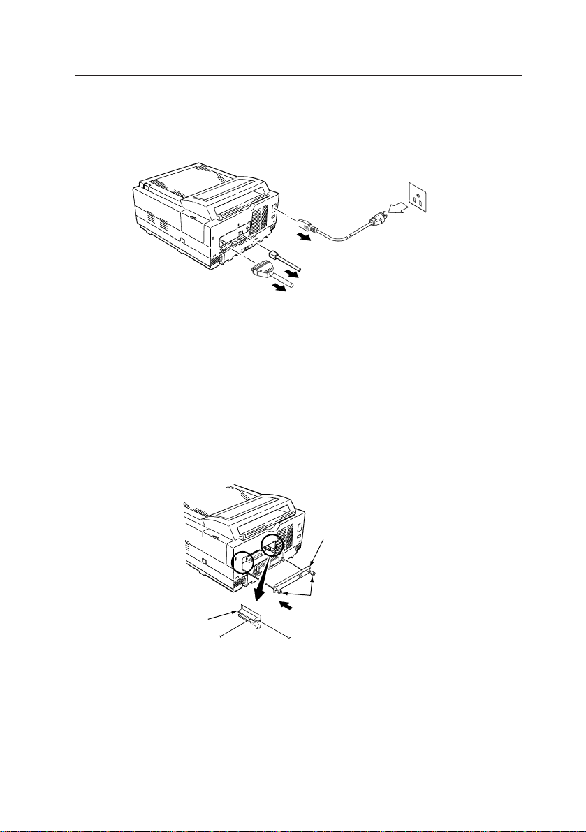
2. INSTALLING NETWORK CARD
[1] Before dismount the Network card
Turn the printer power off and disconnect the AC power and interface
cable.
Caution: Disconnect the AC power cable from the AC outlet before dis-
connection from the printer.
[2] At mount the Network card
the metal mount
screw
the guide
Push the board
Hold the board by the metal mount, and insert it into the guides. Push the
board firmly but carefully into the printer until the metal mount comes into
contact with the printer housing. And fix the two screws in the metal
mount.
Take care that the side with the expansion slots is upwards and the connector is towards the printer.
5
Page 12
10 Base-T Ethernet network adapter card
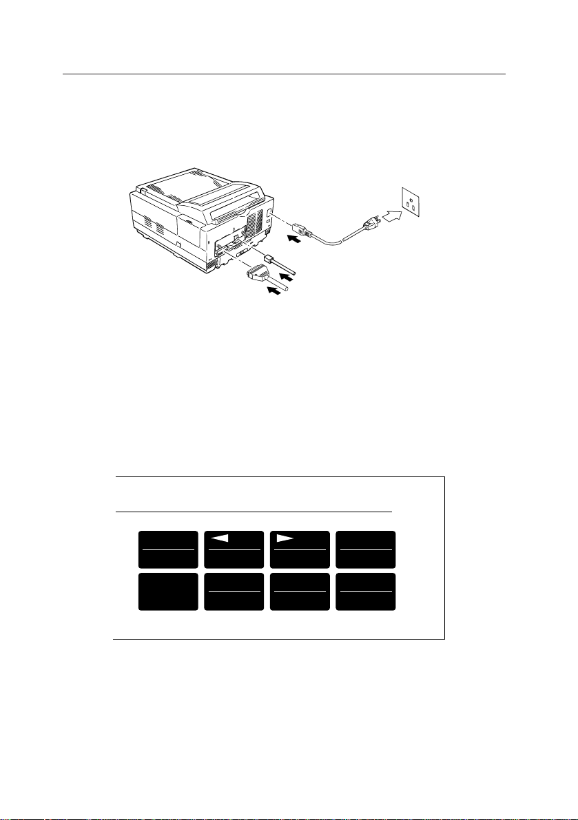
[3] After mount the Network card
Reconnect the AC power and interface cables.
Caution:Reconnect the AC power cable to the printer before connecting
to the AC mains outlet.
[4]
OKIPAGE 12i
PAGE PRINTER
MENU1
Menu2
ON LINE
Recover
PAPER SIZE
Print Menu
Press 2 Seconds
Reset
TRAY TYPE
Print Fonts
Turn the printer power on and take the printer off-line by pressing ON-
LINE button. Press MENU1/MENU2 button for less than two second.
When PERSONALITY appears in message window, repeat pressing
MENU1/MENU2 button till HOST I/F appears in message window . Press
ENTER/POWER SAVE button.
6
ENTER
Power Save
FORM FEED
Print Demo
Page 13

2. INSTALLING NETWORK CARD
Press MENU1/MENU2 button 2 times.
Press either
tt
t/RECOVER or
tt
to change window message to NETWORK ENABLE*.
If message NETWORK is not appeared in message window, turn printer
off and recheck installation of the Network board.
ss
s/RESET and ENTER/PWER SA VE button
ss
7
Page 14

10 Base-T Ethernet network adapter card
3. NETWORK SETUP FOR EACH OPERATING SYSTEM
3.1 Network Client -Server Correspondence
This network card supports those network environments shown in the
table below:
Server Client
Windows NT Server
NetWare3.1x
(R-Printer Mode)
(Q-Server Mode)
NetWare4.1x
(Bindery R-Printer Mode)
(Bindery Q-Server Mode)
(NDS R-Printer Mode)
UNIX-based Workstation
Macintosh
Windows95 (Peer to Peer)
Windows NT Workstation
Windows 95
MS-DOS
Windows3.1
Windows for Workgroup3.11
Windows95
Windows NT Workstation
MS-DOS
Windows3.1
Windows for Workgroup3.11
Windows95
Windows NT Workstation
UNIX-based Workstation
Macintosh
Windows95 (Peer to Peer)
3.2 Setting Up Servers
3.2.1 Setting up Windows NT4.0 Server
Printer administrative tool
General Web Browsers
Telnet
OkiView
PCONSOLE
OkiView
PCONSOLE
NetWare Administrator
OkiView
Telnet,
UNIX Utility
General Web browsers
Telnet
Log on to the Windows NT from the administrator account or an account
of a person who has the administrative privilege.
1 Open the “Control Panel” icon by double-clicking it.
2 Double-click the “Network” icon.
3 Click “Add...” button on “Service” screen to add “Microsoft TCP/
IP print”.
4 Click “OK” button and end setting up “Network” .
8
Page 15

3. NETWORK SET UP FOR EACH OPERATION SYSTEM
5 Double-click “Printer” icon.
6 Double-click “Add Printer”.
7 “Printer add wizard” is displayed. For printer management, select
“This computer” and click “Next>” button.
8 On the port selection screen, click “Add port...” button.
9 Select “LPR Port” on “Printer Port” screen and click “New Port...”
button.
0 On “Add LPR compatible printer “ screen, enter IP address *1 to
be assigned to this Network card in the text box “Server name or
address which provides lpd:” , and an appropriate name by which
this printer name can be distinguished from others on the network,
in the text box “Printer name or printer queue name on the
Server:”, and click “OK” button.
A The address and the printer name just added are added to “Usable
ports” of “Printer Add Wizard” and the check box(es) is checked.
B Click “Next” button.
C Click “Use disk...” of “Printer Wizard”.
D Insert Install disk which comes with the printer into the disk drive
and click “OK” button.
E Add the printer driver, according to the messages of the setup
screen.
F Click “Print test page” button from “Printers” of the Control Panel.
The set up is complete when the test pages are printed.
*1 For the IP address setup when DHCP Server is used, please
refer to Section 3.2.6, “Setting up IP Address in DHCP Server
Environment”.
3.2.2 Setting up Windows NT3.51 Server
Log on to the Windows NT from the administrator account or an account
of a person who has the administrative privilege.
1 Open the “Control Panel” icon by double-clicking it.
2 Double-click the “Network” icon.
3 Click “Add software...” button on “Network setup” screen.
4 On “Add Network software” screen, select “TCP/IP protocol and
relevant components” and click “Continue” button.
5 On “Windows NT TCP/IP installation option” screen, check “TCP/
IP network print support” check box and click “Continue” button.
6 When “Windows NT Setup” screen is displayed, set Windows
9
Page 16

10 Base-T Ethernet network adapter card
NT distributed file(s) to the drive, enter full path and click
“Continue” button.
7 Click “OK” button. Then “Change Network setup” screen is
displayed. Reboot the system following the message shown.
8 Double-click “Print Manger” icon.
9 Pull down “Printer” menu and open “Create a printer...”.
0 Select “Other...” of “Print to” and click “OK” button.
A On “Print to” screen, select “LPR Port” for “Print monitor that can
be used:”, and click “OK” button.
B On “Add LPR compatible printer “ screen, enter IP address
assigned to this Network card in the text box “Host name or
address which provides lpd:” , and an appropriate name by which
this printer can be distinguished from others on the network, in
the text box “Computer printer name:”, and click “OK” button.
C When you return to the “Create a printer” screen, select “Others...”
in “Driver” and click “OK” button.
D When “Install driver” screen is displayed, insert the Install disk
which comes with the printer in the disk drive, enter the full path
in the text box and click “OK” button.
E When the installation is completed, the printer is connected to
the print manager.
*2
*2: For the IP address setup when DHCP Server is used, please
refer to Section 3.2.6, “Setting up IP Address in DHCP Server
Environment”.
3.2.3 Setting up NetWare3.1X File Server
3.2.3.1 Setting up Remote Printer Mode
This chapter describes this network card connection to the existing print
server.
For how to create a print server, please refer to the manual attached to
your NetWare.
1. Preparation
1 Log in to File Server by the supervisor account (or user name
which has a supervisor privilege).
2 Boot up PCONSOLE.
10
Page 17

3. NETWORK SET UP FOR EACH OPERATION SYSTEM
2. Creating print queue
If an already existing print queue is to be used, skip this and next section
and go to “4. Registering a Printer in a Print Queue”.
1 Open “Print Queue Information” from “Available Options” and
press the Insert key in “Print Queues”.
2 Type a name of print queue you are going to create in the text
box “New Print Queue Name: ”. (Make sure not to use an already existing print queue name.)
3 Push the ESC key to return to the “Available Options” window.
3. Registering a print queue to the print server
1 From “Available Options,” select and open “Print Queue Infor-
mation.” Select the desired print queue from “Print Queues” and
press the Enter key. From “Print Queue Information,” select
“Queue Servers” and press the Enter key. The “Quere Servers”
window will open. Press the Insert key in the window. The “Queue
Server Candidates” window will open. Select the print server to
be connected from the window and press the Enter key.
2 Press the ESC key to return to the “Available Options” window.
4. Registering a printer to Print Queue
1 Open “Print Server Information” from “Available Options” and
select a print server to which you wish to attach a print queue,
from “Print Servers”.
2 Open “Print Server Configuration” from “Print Server Information”.
3 Open “Printer Configuration” from “Print Server Configuration
Menu”.
4 Select “Not Install” in “Configured Printers” and press the Enter
key . Then the Configuration window opens with a default printer
name.
5 Press the Enter key in the text box “Name:” . Then you are
prompted to enter a printer name. Type in a printer name you
wish to register. (Make sure not to use an already existing printer
name.)
6 Press the Enter key in the text box “Type:” and select “Remote
Other/Unknown” from “Printer types”.
11
Page 18

10 Base-T Ethernet network adapter card
7 Press the ESC key and select “Yes” in “Save changes”.
8 Press the ESC key repeatedly to return to “Available Options”.
9 Press the ESC key and select “Yes” in “Exit PConsole”. The
setup is completed.
5. Starting the print server and connecting this network card
• When print server is used on the file server:
Load PSERVER.NLM. The PSERVER.NLM has been copied to
SYS:SYSTEM when the file server was installed.
1 Enter the following in the system console of the file server:
LOAD PSERVER print server name
2 To exit the print server, press Alt key and Esc key simultaneously
to return to the system console and enter the following:
UNLOAD PSERVER print server name
• When workstation is used specifically as the print server:
Execute PSERVER.EXE. The PSERVER.EXE and the relevant files
have been copied to SYS:PUBLIC when the file server was installed.
1 To start up the print server, these files must be accessed. Log in
to the file server and map the search drive to SYS:PUBLIC or
copy the necessary files to the local floppy disk or hard disk.
2 Change SHELL.CFG file or NET.CFG file so that the workstation
dedicated to the print purpose can support adequate connections. Which CFG file you will edit depends on the NetWare client that has been installed.
Type the following line in SHELL.CFG or NET.CFG:
SPX CONNECTIONS = 60
3 Boot MS-DOS and NetWare shell. To do so, enter the following
at prompt of the workstation dedicated to print:
PSERVER file server name/print server name
4 To close the print server, close it from PCONSOLE. Enter
PCONSOLE from the client and start PCONSOLE.
5 Select “Print Server Information” from “Available Options”. Se-
lect the print server you wish to stop, from “Print Server” list.
6 Select “Print Server Status/Control” from “Print Server Informa-
tion” menu.
7 Select “Server Info” from “Print Server Status and Control” menu.
12
Page 19

3. NETWORK SET UP FOR EACH OPERATION SYSTEM
8 Press the Enter key in the “Print Server Info/Status” window. If
you select “Down” , the print server stops right away. If you select “Going down after current jobs”, the server goes down after
the current print job is completed.
3.2.3.2 Setting Queue Server Mode
This network card can serve as a print server and connect Print Queues.
Set print server, print queue and printer in the File Server in the same
manner as described in Section 3.2.3.1, “Setting Up Remote Printer Mode”.
If the Print Server is not booted up on the file server side, this network
card of AUTO or Queue Server Mode is connected to the file server as a
print server.
Caution:
• To use OKIPAGE 12i printer in Queue Server Mode, you must not set
the password for the print server. If you set the password, you will not
be able to connect this NETWORK card as a print server. To use
OKIPAGE 12i in Remote Printer Mode, you can connect it without
problem even if the password is set for the print server.
• This network card does not support the banner sheet in the Queue
Server Mode. Even if you specify the banner sheet print, it will be
ignored.
3.2.3.3 Message display in Remote Printer Mode
This network card temporarily stops receiving next queue(s) while receiving a job in the NetWare Remote Printer Mode, according to the Specification. At this, NetWare server side handles this as temporary disconnection and a message to that effect is sent to the Client side. Once the
network card completes receiving of the current job, however, the connection with next queue is made, and receive process starts normally. It
is possible to change the display interval of the message from NetWare
server and user(s) for whom the message is displayed. You may change
the settings as you see fit.
1. Setting from Client using Windows95 MICROSOFT NetWare Client
Service
13
Page 20

10 Base-T Ethernet network adapter card
1 Log in to the NetWare file server from supervisor account.
2 Start PCONSOLE from the NetWare file server volume at MS-
DOS Prompt.
3 Open “Print Server Information ”from “Available Options” window .
4 Select the print server for which you are changing the notification
settings from “Print Servers” window and press Return key.
5 Select “Print Server Configuration” from “Print Server Informa-
tion” window and press Return key.
6 Select “Notify List for Printer” from “Print Server Configuration
Menu” window and press Return key.
7 Select the printer name for which you are changing the notifica-
tion settings from “Defined printers” window and press Return
key . Notification message is displayed to users displayed in the
window opened here. If no user name is displayed here, no notification is issued. To confirm or change the notification interval,
please proceed to 8.
8 The settings of the notification interval are displayed in “First”
and “Next” columns of the user list opened in 7 above. “First”
shows the time to issue the first notice and “Next” shows the
issuance interval from one notice to the next notice. The time is
expressed in seconds.
9 To change the notification interval, select target user(s) from the
user list opened in 7 above and press Return key. Change “First”
and “Next” to desired times on “Notify Interval” window, press
ESC key, select “Yes” on “Save changes” window and press Return key.
0 To delete the user(s) to be notified, select the target user(s) from
the user list opened in 7 above and press Delete key. Select
“Yes” on “Delete Object From Notify List” and press Return key.
A To add a user to be notified, press Insert key with the user list
open state in 7 above. Select user(s) or a group you wish to
add from “Notify Candidate” window and press Return key. Then
“Notify Intervals” window is displayed. Enter time of your choice
in “First” and “Next” and press ESC key. Select “Yes” on “Save
changes” window and press Return key.
B After you confirm the notification settings and/or complete chang-
ing of the settings, end PCONSOLE.
C Restart the print server to make the setting changes effective
14
Page 21

3. NETWORK SET UP FOR EACH OPERATION SYSTEM
3.2.4 Setting Up Remote Printer in NetWare 4.1x NDS Environment
3.2.4.1 Setting up the remote printer using the NetWare administra-
tor utility
You need to set up the print queue, the print server and the printer in the
NetWare environment in order to use this network card in the remote
printer mode.
This subsection describes how to set them up, using an example in which
“NetWare Administrator Utility” (NWADMIN, hereafter), the Netware4.1x
administration tool is used. The client is Windows95 to which NetWare
Client32 has been installed.
1. To start up NetWare client
1 Start up the NetWare client PC. Log in to the NetW are4.1x server
from admin (or an account which is granted the administrator
privilege.)
2 Start the NWADMIN. The current NetWare resources are dis-
played in the form of a tree.
2. To create a print server
If an already existing print server is to be used, please proceed to “3.
To create the print queue”.
1 Click the directory where you wish to set the print server, on
NWADMIN’s main window, to select.
2 Select “Create...” from “Objects” menu and open “New Object
Class” screen.
3 Select “Print server” from the “Object class:” list and press “OK”
button.
4 Enter the name of the print server you will create in the text box
“Print server name:” on the “Create print server” screen, and click
“Create” button. (Make sure not to use an already existing print
server name.) Details on how to set the print server will be
described later.
3. To create a print queue
If an already existing print queue is to be used, proceed to “4. To
create a printer”.
15
Page 22

10 Base-T Ethernet network adapter card
1 Click the directory where you wish to set the print queue, on
NWADMIN’s main window, to select.
2 Select “Create...” from “Objects” menu and open “New Object
Class” screen.
3 Select “Print queue” from the “Object class:” list and press “OK”
button.
4 On the “Create print queue” screen, check “Directory service
queue” and enter the name of the print queue you will create, in
the text box “Print queue name:”. (Make sure not to use an
already existing print queue name.)
5 Enter the name of the volume where print jobs of the print queue
are saved in the text box “Print queue volume:”. You can find
the volume from the directory tree. If the volume is selected from
the directory tree, go to 6, the next item. If the volume is directly
typed in, go to 7.
6 Click the tree button beside the text box. Specify the directory
where the target object is located, from the “Directory context:”
list of “Select object” screen. Select the object where print jobs
will be saved, from the “Object:” list. When the object is selected, the name of the object is displayed in the text box “Selected object:”. Click “OK” button.
7 Click “Create” button on the ”Create print queue” screen.
4. To create a printer
1 Click the directory where you wish to set up the print queue, on
NWADMIN’s main window, to select.
2 Select “Create...” from “Objects” menu and open “New Object
Class” screen.
3 Select “Printer” from the “Object class:” list and press “OK” but-
ton.
4 Enter the name of the printer you will create in the text box “Printer
name:” on the “Create printer” screen, and click “Create” button.
(Make sure not to use an already existing printer name.)
5. To connect the printer to the print queue
1 On the NWADMIN’s main window, click the printer newly cre-
ated, to select it.
2 Select “Details...” from the “Object” menu and open “Printer:
‘Printer name’” screen.
16
Page 23

3. NETWORK SET UP FOR EACH OPERATION SYSTEM
3 Click “Assign” button.
4 Click “Add...” button and open the “Select object” screen.
5 Open the directory where the print queue to which the printer is
to be connected is located, from the “Directory context:” list.
6 From the text box “Object:”, select the print queue to which the
printer is to be connected. Then the print queue name is displayed in the text box “Selected object:”. Click “OK” button.
7 Click “Set environment” button on “Printer: ‘Printer name:’” screen.
8 Change the text box “Printer type:” to “Others/unknown”.
Caution: You must set this as described. If you omit this, this
network card will not run.
9 Click “OK” button to return to the NWADMIN’s main window.
6. To connect the printer to the print server
1 On the NWADMIN’ s main window, click the print server to which
you wish to connect the printer, to select it.
2 Select “Details...” from the “Object” menu and open “Print server:
‘Print server name’” screen.
3 Enter the print server name in “Advertising name”.
4 Click “Assign” button.
5 Click “Add...” button and open the “Select object” screen.
6 Open the directory where the printer which you wish to connect
to the print server is located, from the “Directory context:” list.
7 Select the printer you wish to connect to the print server , from the
text box “Object:”. Then the printer name is displayed in the text
box “Selected object:”. Click “OK” button.
Items to be confirmed after the print environment has been set up
When you complete the environment setting with NWADMIN, please con-
firm the following items once more:
PrintQueue:
Open “Assign” and confirm that the print server and the printer that you
have set are displayed in “Administered Print Servers” and “Printers for
which print queues are serviced”, respectively.
If they are not displayed, do the setting once again in the Print Server and
Printer “Details” window.
17
Page 24

10 Base-T Ethernet network adapter card
Print Server:
Make sure that “Advertising name” matches the print server name. If
they do not match, enter the print server name in “Advertising name”.
Open “Assign” and confirm that the printer that you have set is displayed
in the “Printers”. If the printer is not displayed, click “Add” button and
select the printer from the list to connect it. If the printer is not displayed
in the list, it is created in a different context.
Confirm that the printer number is among 0 through 15.
Open “Print Layout” and confirm that Print server – Printer – Print Queue
that have been set are connected.
Click “Change password” button and check if the password is set in “Cur-
rent password.” If the password is set, this Network card cannot make a
connection in Queue Server Mode. To use this Network card in the Queue
Server Mode, leave the password blank.
Printer:
Open “Assign” and confirm that the print queue(s) you have set is displayed. If it is not displayed, click “Add” button and select the PrintQueue
from the list to connect it. If PrintQueue is not displayed in the list,
PrintQueue is created in a different context.
Open “User Environment Setup”, and confirm that “Printer T ype” is set to
“Other/Unknown”. The default of “Printer Type” is “Parallel”, and this must
be set to “Other/Unknown”.
3.2.4.2 Setting up the remote printer using PCONSOLE
In order to use this network card in the remote printer mode, you must set
up the print queue, the print server and the printer in the NetWare environment.
This subsection describes how to set them using PCONSOLE of the
NetWare 4.1x.
18
Page 25

3. NETWORK SET UP FOR EACH OPERATION SYSTEM
1. To start the NetWare client
1 Start the NetWare client PC. Log in to the NetWare4.1x server
from admin (or the account to which the administrator privilege
has been granted).
2 Start PCONSOLE.
2. To create a print queue
1 Select “Change context” from “Items that can be used”.
2 Press Insert key in the text box “Enter context:”
3 Move the cursor to the directory where you will create a print
queue from “Object, Class” and press F10 key. The context is
displayed at upper left area of the PCONSOLE screen. Make
sure that this matches with the context you wish to have.
4 Select “Print queue” from “Items that can be used”, and open the
“Print queue” list.
5 Press the Insert key, type the name of a print queue you will
create in the text box “New print queue name:” and press the
Enter key . (Make sure not to use an already existing print queue
name.)
6 Press the Insert key in the text box “Print queue volume:”, select
the volume where a print queue will be created, from “Object,
class” and press the Enter key.
7 The newly created print queue name is added to “Print queue”.
3. To create a print server
1 Select “Change context” from “Items that can be used”.
2 Press Insert key in the text box “Enter context:”
3 Move the cursor to the directory where you will create a print
server from “Object, Class” and press F10 key. The context is
displayed at upper left area of the PCONSOLE screen. Make
sure that this matches with the context you wish to have.
4 Select “Print server” from “Items that can be used”, and open the
“Print server” list.
5 Press the Insert key, type the name of the print server you wish
to create in the text box “New print server name:” and press the
Enter key . (Make sure not to use an already existing print server
name.)
6 The newly created print server name is added to “Print server”.
19
Page 26

10 Base-T Ethernet network adapter card
4. To create a printer
1 Select “Change context” from “Items that can be used”.
2 Press the Insert key in the text box “Enter context:”.
3 Move the cursor to the directory where you will create a printer
from “Object, Class” and press F10 key . The context is displayed
at upper left area of the PCONSOLE screen. Make sure that this
matches with the context you wish to have.
4 Select “Printer” from “Items that can be used”, and open the “Print-
ers” list.
5 Press the Insert key, type the name of the printer you wish to
create in the text box “New printer name:” and press the Enter
key. (Make sure not to use an already existing printer name.)
6 The newly created printer name is added to “Printers”.
7 Select the newly created printer from “Printers” and open “Set
printer environment of ‘Printer name’”.
8 Press the Enter key in “Printer type:”, select “Other/Unknown”
from the “Printer type” list and press the Enter key.
Caution: You must set this. If you omit this, this network card
will not run.
9 Press the ESC key to save the change and complete the printer
environment setup.
5. To define the printer and connect it to the print server’s print queue
1 Select “Change context” from “Items that can be used”.
2 Press the Insert key in the text box “Enter context:”.
3 Move the cursor to the directory where the target print server is
located, from “Object, class” and press the F10 key. The context is displayed at upper left area of the PCONSOLE. Make sure
that this matches with the context you wish to have.
4 Select “Print servers” from “Items that can be used” to open the
“Print Servers” list.
5 Select the print server you wish to connect the printer to, from
the “Print servers” list, and press the Enter key.
6 Select “Printers” from “Print server information” and press the
Enter key.
7 Press the Insert key in “Service printers”, select the directory
where the printer you wish to connect is located from “Object,
class”, press the Enter key to have the name of the printer to be
connected displayed, and select it.
20
Page 27

3. NETWORK SET UP FOR EACH OPERATION SYSTEM
8 When the printer name is displayed in “Service printers”, press
the Enter key to open the “Set printer environment of ‘Printer
name’”.
9 Select “Assign print queue:” and press the Enter key.
0 Press the Insert key in “Print queues”, select the print queue to
connect from “Object, class” and press the Enter key.
A When the print server to be connected to is displayed in “Print
queues”, press the ESC key, and press ESC key to close the
“Set printer environment of ‘printer name’”, too.
B Press the ESC key in “Service printers” to end.
Caution:You must set the “Service printer” of 9 above. If you omit this
setting, this network card will not function correctly.
3.2.5 Setting up queue server mode in NetWare 4.1x NDS environ-
ment
This network card does not support the NDS queue server mode.
Please use the network card in the NDS remote printer mode or the queue
server mode in the Bindery environment.
Caution:This Network card does not support the Banner sheet in Queue
Server Mode. Even if you specify the Banner Sheet Printing, it
will be ignored.
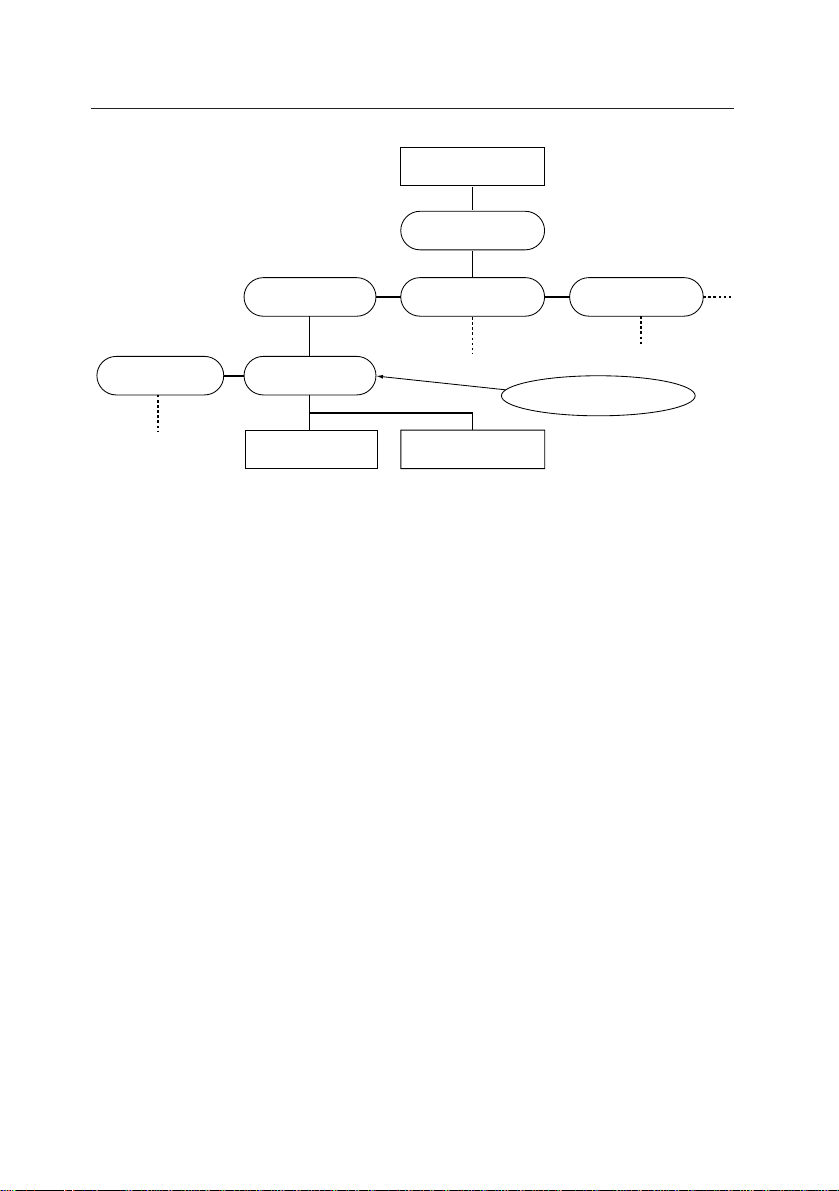
3.2.6 Setting in NetWare4.1x Bindery environment
To use the Bindery Service, set the Bindery context in the NetWare4.1x
environment and set the print server and print queue there.
3.2.6.1 Setting up Bindery Context
To use the Bindery Service, you must set the Bindery Context.
For setting the Bindery Context, you use the set command in the system
console of the NetWare4.1x server.
This subsection describes how to do this, using an example in the net-
work which is the NDS environment, except for DV2.
In the explanations, [RET] means to press the Return key.
21
Page 28
10 Base-T Ethernet network adapter card
Root
(O)=COMPANY
(OU)=MARKET (OU)=FACTORY(OU)=DESIGN
O=Organization
OU=Department
(OU)=DV1
(OU)=DV2
Bindery set up
DV2PSVR DV2PQUE
Type the following in the system console of the NetWare4.1x server:
SET BINDERY CONTEXT = DV2.DESIGN.COMPANY[RET]
You can also set the Bindery Context by directly editing the
AUTOEXEC.NCF file and adding the above SET statement.
With this setting, DV1 or other departments can access the resources of
DV2’s, using the Bindery Service.
3.2.6.2 Setting up the print environment to the Bindery environment
To set the print environment in the NetWare4.1x Bindery environment,
you need to create a print environment in the Bindery Context.
In the client PC to which NetWare Client 32 has been installed, log in to
the Bindery Context from the admin account (or an account to which an
administrator privilege is given), by specifying the Bindery when you are
logging in.
To log in, you need to log in to the NDS server. Select NDS server in the
NetWare Client32 Log-In Window, and log in without checking the Bindery Connection check box.
After logging in from the admin account (or an account to which an ad-
22
Page 29

3. NETWORK SET UP FOR EACH OPERATION SYSTEM
ministrator privilege is given), set the print queue, the print server and
the printer for the Bindery Context with the PCONSOLE or the NetWare
Administrator.
For how to use the PCONSOLE and NetW are Administrator , please refer
to the subsection 3.2.4.1, “Setting up the remote printer using the NetWare
Administrator Utility,” and the subsection 3.2.4.2, “Setting up the remote
printer using PCONSOLE.”
For the details of the NetWare4.1x Bindery Service, please refer to the
Reference Manual of NOVELL NetWare4.1x.
3.2.6.3 About the message display in Remote Printer Mode
This network card temporarily stops receiving next queue(s) while receiving a job in the NetWare Remote Printer Mode, according to the Specification. At this, NetWare server side handles this as temporary disconnection and a message to that effect is sent to the Client side. Once the
network card completes receiving of the current job, however, the connection with the next queue is made, and receive process starts normally .
It is possible to change the display interval of the message from NetW are
server and user(s) for whom the message is displayed. You may change
the settings as you see fit.
1. Setting from Client in PCONSOLE using Novell Client32 client serv-
ice
1 Log in to NetWare file server from admin account. Here uncheck
the Bindery connection check box in the Client32 login window
and log in.
2 Start PCONSOLE from the NetWare file server volume at MS-
DOS prompt.
3 From “Items that you can use” window, select “Print Server” and
press Return key.
4 From “Print Server” window , select the target print server for which
you are changing the notification settings and press Return key.
5 From “Print server information” window, select “Printers” and press
Return key.
6 From “Service printers” window, select the printer name for which
you are changing the notification settings and press Return key.
23
Page 30

10 Base-T Ethernet network adapter card
7 Select “Notify:” in the “Printer xx environment setting” (xx: printer
name) and press Return key. Notification message is displayed
to the users displayed in the user list opened here. If no user
name is displayed here, no notification is issued. To confirm or
change the notification interval, proceed to 8.
8 The settings of the notification interval are displayed in “First”
and “Next” columns of the user list opened in 7 above. “First”
shows the time to issue the first notice and “Next” shows the
issuance interval from one notice to the next notice. The time is
expressed in seconds.
9 To change the notification interval, select target user(s) from the
user list opened in 7 above and press Return key. Change “First”
and “Next” to desired times on “Notify Interval” window, press
ESC key, select “Yes” on “Save changes” window and press Return key.
0 To delete the user(s) to be notified, select the target user(s) from
the user list opened in 7 above and press Delete key. Select
“Yes” on “Delete Object From Notify List” and press Return key.
A To add a user to be notified, press Insert key with the user list
open state in 7 above. From “Object/Class” window, select an
object(s) you wish to add and press Return key. Then “Notify
Interval” window is displayed. Enter time of your choice in “First”
and “Next” and press ESC key. In the “Save changes” window,
select “Yes” and press Return key.
B After you confirm the notification settings and/or complete chang-
ing of the settings, end PCONSOLE.
2. Setting from Client which uses Novell Client32 client service, with
NetWare administrator utility
1 Log in to NetWare file server from admin account. Here uncheck
the Bindery connection check box in the Client32 login window
and log in.
2 Start NWADMIN.
3 From main window , select the printer object(s) for which you are
changing the notification settings and double click it, or select
“Details...” of “Object” menu to display the detailed information.
4 Click “Notify” button. Objects which are the target of notification
are displayed in “Notify” list. “First” shows the time to issue the
first notice and “Next” shows the issuance interval from one notice to the next notice. The time is expressed in seconds.
24
Page 31

3. NETWORK SET UP FOR EACH OPERATION SYSTEM
5 To change the notification interval, select the object(s) you wish
to change from “Notify” list opened in 4 and press Return key.
Change “First” and “Next” to desired times on “Notify Setting
window.
6 To delete the object(s) of notification, select the intended object(s)
in the “Notify” list opened in 4 and press “Delete” button.
7 To add a user to be notified, press “Add” button in the “Notify” list
opened in 4. Change the context to the one in which the object(s)
you wish to add is located, on “Select object” window. Select the
target object when it is displayed in the “Objects that can be used”
list, and press “OK” button. You can set the notification interval
in the procedures described in 5 above.
8 When you complete setting of the notification interval, press “OK”
button, return to main window, and end NWADMIN.EXE.
3.2.7 About the IP address setting in DHCP server environment
In the network environment where the DHCP (Dynamic Host Configuration Protocol) server is used in the network server, the IP address of this
network card is automatically assigned by the DHCP server.
We strongly recommend that the IP address be used fixed when this
network card is used, but in some DHCP server, the IP address cannot
be fixed. For the DHCP server specifications, please refer to the manual
which comes with the DHCP Server.
In order to use the DHCP’s IP address auto assignment function, you
must set the DHCP Request of this network card to ON. (This is set to
OFF at factory shipping.)
The DHCP Request ON\OFFcan be set either in the printer’s level 2 menu
or using the OkiView utility or the Web server/Telnet.
It will take about 30 seconds to complete rewriting of the setting change.
Then, set the printer to OFF-LINE and then to ON-LINE, using the ONLINE button of the printer or turn the printer’s power off and on again.
Caution:If both DHCP and RARP are set to ON, a serious error will
result on network. Never set both to ON.
25
Page 32

10 Base-T Ethernet network adapter card
3.2.8 Setting up the UNIX server
This section describes the UNIX type network environment setup without
using the UNIX utility.
If you are going to use the UNIX utility, please refer to the Readme file
attached to the UNIX utility”.
3.2.8.1 IP address and host name in the host table
Using the following procedure, add the IP address and the host name
(printer name) to the host table:
1 Get the IP address which is not used from the network adminis-
trator and determine a unique name for this network card.
2 Add the IP address and the host name to the host table of the
system. In almost all the UNIX systems, you can do this by adding the following line to /etc/hosts file:
<IP address> <host name>
3 Update the data base. If the system uses data base such as
Yellow Pages (YP) and Network Information Services (NIS), these
must be updated. In almost all the UNIX systems, you can do
this by entering the following commands:
cd /var/yp
make
3.2.8.2 Printer data base
To allow the printer to function correctly in the UNIX line printer system,
you must create the /etc/printcap file. In the printcap data base, information on the line printer directly connected to a certain machine and the
printer(s) that can be used via network is registered.
For the details of the printcap, please refer to the UNIX On-Line Manual
Page or Reference Manual.
This subsection describes how to create the /etc/printcap file, using an
example in which the remote machine name, the printer name and the
spool directory name were set to OKIPAGE 12i.
26
Page 33

3. NETWORK SET UP FOR EACH OPERATION SYSTEM
First, create a directory OKIPAGE 12i under the directory /ver/spool/lpd.
The printcap entry is composed of fields enclosed with colons ( : ). The
last field must end with a colon. Describe the name of the printer in the
first field of each entry . Start from the left margin, without placing a colon
at the head.
Example:
# printcap entry for OKIPAE 12i PAGEPRINTER on Network
OKIPAGE 12i:\
:lp=\
:rm=OKIPAGE 12i:\
:rp=OKIPAGE 12i:\
:lf=/var/adm/lpd-errs: \
:sd=/var/spool/lpd/ OKIPAGE 12i:
If there is # at the beginning of the line, this line becomes a comment.
If you enter a carriage return without a space character after a back slash
(\), this entry continues to the next line. Please note that if you enter a
space character at the end of the printcap line, by mistake, a serious
error will occur. In this example, a tab is set for the left margin for the
continuing lines. And a continuing line of any entry must begin with a
space character, normally with a tab character. If an entry continues to
the second line or more, you must place a colon at the end of each line
and the beginning of next line.
Meaning of each entry
lp: device name to open for output
Specify the name of the file to open for output.
For a printer which resides in the remote host, there must be an
empty entry.
rm: machine name for remote printer
Specify the name of the remote machine connected.
This name must be an already known host name of the machine on the network.
rp: remote printer name argument
Indicates that the printer name on the remote machine is
OKIPAGE 12i.
27
Page 34

10 Base-T Ethernet network adapter card
lf: error logging filename
Specify the file which records the spooler errors.
You can create it at an arbitrary place, but the permission to
write must be already set.
sd: spool directory
Specify the spooling directory.
Make sure that the directory has the correct permission.
3.3 Setting up the Client
3.3.1 Setting Windows95
3.3.1.1 Using OKIP AGE 12i in W indows NT Server4.1x and 3.1x environment
1. Setting Control Panel
1 From Control Panel, double-click the “Network” icon.
2 Make sure that the following items are in the configuration of
“Network setup”. If not, click “Add...” button to add them.
• Client for Microsoft networks
• Net BEUI
• File and printer sharing for Microsoft networks
3 Select “NetBEUI” from the “Current network configuration:“ list
and open Properties.
4 Check the “Microsoft network client” check box and the “Microsoft
network shared service” check box and the “File and printer
sharing for Microsoft Networks” check box, in “Bind” of the
“NetBEUI’s Properties”.
2. Adding a printer
1 From Control Panel, double-click the shortcut of “Printers” to open
it.
2 Double-click the “Add printer” icon.
In “Printer Wizard”, select “Network printer” for Connect To.
28
Page 35

3. NETWORK SET UP FOR EACH OPERATION SYSTEM
3 In the text box “Network path or print queue”, click “Browse” button
and select the printer to connect from the “printer” list.
4 For installing the printer driver, click the “Use disk...” button and
insert the Install disk in the disk drive which comes with the printer.
3. Setting up a printer
1 Open the shortcut of “Printers” from the Control Panel by double-
clicking it.
2 Select the OKIP AGE 12i printer that has been added newly , select
“Set Default Printer” in the “File” menu.
3 Once again, select the OKIPAGE 12i printer, and open the
“Properties” from the “File” menu.
4 Confirm that the “Print to port:” of the “Details” is set to the network
printer of your choice.
5 If the network printer of your choice is not set to the network
printer, select one from the “Print to port:” list.
6 If you cannot find it in the list, click “Add port...” button, and click
“Browse” from the “Add port” screen to select.
3.3.1.2 Using OKIPAGE 12i in the NetWare 3.1x environment
1. Setting the Control Panel
1 Double-click the “Network” icon from the Control Panel.
2 Make sure that the following items are in the configuration of the
“ Network setup”. If not, click the “Add...” button to add them.
• NetWare Network Client
• IPX /SPX Compatible Protocol
3 From the “Current network configuration:” list, select “IPX/SPX
Compatible Protocol” and open the Properties.
4 Check the “NetWare network client” check box in “Bind” of the
29
Page 36

10 Base-T Ethernet network adapter card
“IPX/SPX Compatible Protocol’s Properties”. If there are other
network items, check other network items, too, according to the
network environment.
2. Adding a printer
Refer to the sub-section 3.3.1.1, “Using OKIPAGE 12i in Windows NT
Server 4.1x & 3.1x environment, 2. Adding a printer”.
3. Setting up a printer
Refer to the sub-section 3.3.1.1, “Using OKIPAGE 12i in Windows NT
Server 4.1x & 3.1x environment, 3. Setting up a printer”.
3.3.1.3 Using OKIPAGE 12i in NetWare 4.1xNDS environment
1. Setting the Control Panel
1 Double-click the “Network” icon from the Control Panel.
2 Make sure that the following items are in the configuration of the
“ Network setup”. If not, click the “Add...” button to add them.
• Novell NetWare Client 32 (provided by Novell Corp.)
• IPX 32-bit Protocol for Novell NetWare Client 32 (provided by
Novell Corp.)
2. Log in to the NDS Tree when Windows95 is rebooted.
3. Adding a printer
Please refer to the subsection 3.3.1.1, “Using OKIPAGE 12i in the Win-
dows NT Server 4.1x&3.1x environment, 2. Adding a printer”.
4. Setting up a printer
Please refer to the subsection 3.3.1.1, “Using OKIPAGE 12i in the Win-
dows NT Server 4.1x&3.1x environment, 3. Setting up a printer”.
30
Page 37

3. NETWORK SET UP FOR EACH OPERATION SYSTEM
3.3.1.4 Using OKIPAGE 12i in NetWare4.1xBindery environment
1. Setting the Control Panel
1 Double-click the “Network” icon from the Control Panel.
2 Make sure that the following items are in the configuration of the
“Network setup”. If not, click the “Add...” button to add them.
• Novell NetWare Client 32 (provided by Novell Corp.)
• IPX 32-bit Protocol for Novell NetWare Client 32 (provided by
Novell Corp.)
2. Log in to the Bindery Context in the bindery mode when the Windows95 is rebooted.
3. Adding a printer
Please refer to the subsection 3.3.1.1, “Using OKIPAGE 12i in the Windows NT Server 4.1x&3.1x environment, 2. Adding a printer”.
4. Setting up a printer
Please refer to the subsection 3.3.1.1, “Using OKIPAGE 12i in the Windows NT Server 4.1x&3.1x environment, 3. Setting up a printer”.
3.3.2 Setting Windows3.1
3.3.2.1 Using OKIPAGE 12i in TCP/IP environment
In order to use TCP/IP applications such as ftp and lpr on Windows3.1
system, you must install TCP/IP software onto Windows3.1.
TCP/IP software is not attached to Windows3.1. Obtain TCP/IP software on market, say, FreeWare and install it.
For the installation and the use of the TCP/IP software, please refer to
the manual, etc., which come with the TCP/IP software.
31
Page 38

10 Base-T Ethernet network adapter card
3.3.2.2 Using OKIPAGE 12i in NetWare3.1x environment
If you specify that the Windows driver be installed as well when installing
the NetWare3.1x client, the utility for the Windows “User T ools” is installed.
1. Setting up the network connection with “User Tools”
This subsection describes how to set the Windows3.1x NetWare Cli-
ent using the “User Tools”.
1.1 To install the printer driver (if it is already installed, omit this process.)
1 Install the printer driver from the Install disk which comes with
the printer.
1.2 To assign the print queue to local print
1 Double-click the “User Tools” icon from the “NetW are T ools” group.
2 The volume of the NetWare server to which you have currently
logged in is displayed in the “Resources:” column.
3 If the server to connect to is not displayed in the “Resource:”
column, click “NetWare Connections” button, the third button from
the left, of the nine buttons at the top of the window.
4 Select the server to connect to from the “Resources:” column
and click the “Login” button. Enter the user name and the password, to log in.
5 Click “Device Connections:” button, the second button from the
left.
6 Select the drive name for mapping from “Devices:” and the vol-
ume for mapping from “Resources:” Click “Map” button to assign the volume of the Netware server to the local drive.
7 Click “Printer Connections:” button, the third button from the left.
8 From the “Resources:” column, select a print queue to connect
to this network card and a printer port to assign from “Port:” column, and click the “Capture:” button. Now the assignment of the
print queue to the local port is complete.
9 Click “Exit:” button, the left most button to exit “User Tools”.
32
Page 39

3. NETWORK SET UP FOR EACH OPERATION SYSTEM
2. Setting up the network connection with “Print Manager”
2.1 T o install the printer driver (if it is already installed, omit this process.)
1 Start “Print Manager” from “Main”.
2 Open “Setting a printer..” from the “Options” menu.
3 From the “Select a printer to install:” list, select “Install a printer
not listed or updated printer” and click the “Install...” button.
4 Insert the Installer disk which comes with the printer in the floppy
drive and click the “OK” button.
2.2 To connect the printer to the network
1 In the “Print Manager”, select OKIP AGE 12i from “Installed print-
ers:” and click the “Connect...” button.
2 Select “Connect to:” in “Connect a printer”.
3 “NetWare Printer Connections” of the “User Tools” utility of the
NetWare opens.
4 From the “Resources:” column, select a print queue to connect
to this network card, and a printer port to assign from “Port:” column, and click the “Capture:” button. Now the assignment of the
print queue to the local port is complete. If you cannot find a print
queue which you wish to connect, connect the server ’s volume,
by referring to “1.2 To assign the print queue to local print.”
3.3.3 Setting Windows for Workgroup3.11
3.3.3.1 Using OKIPAGE 12i in Windows NT environment
1. Installing the printer driver
1 Install the printer driver from the Install disk which comes with
the printer.
2. Installing the network driver
1 From “Network” group, double-click the “Network Setup” icon.
2 If “Microsoft NetBEUI” is not in the “Network Drivers:” list on the
“Network Setup” screen, click the “Drivers...” button and open
the “Network Drivers” screen.
3 Click the “Add Protocol...” button, select “Microsoft NetBEUI” from
the “Add Network Protocol” screen, and click the “OK” button.
33
Page 40

10 Base-T Ethernet network adapter card
3. Connecting a printer
1 To enable the “Print Manager”, check the “Use Print Manager”
check box in “Printers” of the “Control Panel”.
2 Double-click the “Print Manager” icon from the “Main” group to
open.
3 Select this printer from the printer list and open “Connect Net-
work Printer...” in the “Printers” menu.
4 Select a local port to assign to “Device Name:” on the “Connect
Network Printer” screen.
5 From the “Show Shared Printers on:” list, select the PCs which
share the printers and have them displayed in “Shared Printers
on:”. Select the printer you wish to use from there and click the
“OK” button.
3.3.3.2 Using OKIPAGE 12i in NetWare3.1x environment
1. Installing the printer driver
1 Install the printer driver from the Install disk which comes with
the printer.
2. Installing the network driver
1 From “Network” group, double-click the “Network Setup” icon.
2 On the “Networks...” screen of the “Network Setup” screen, se-
lect “Novell NetWare [Workstation Shell 3.X]” from the “Others:”
list of the “Install Microsoft windows Network:” and click the “OK”
button.
3 Install the NetWare driver following the messages shown on the
screen.
3. Connecting a printer
1 To enable the “Print Manager”, check the “Use Print Manager”
check box in “Printers” of the “Control Panel”.
2 Double-click the “Print Manager” icon from the “Main” group to
open.
3 Select this printer from the printer list and open “Connect Net-
work Printer...” from the “Printers” menu.
34
Page 41

3. NETWORK SET UP FOR EACH OPERATION SYSTEM
4 Select a local port to assign to “Device Name:” on the “Connect
Network Printer” screen.
5 From the “Show Shared Printers on:” list, select the PCs which
share printers and have the shared printers displayed in “Shared
Printers on:”. Select the printer you wish to use from there and
click the “OK” button.
3.3.3.3 Using OKIPAGE 12i in NetWare 4.1x environment
1. Installing the printer driver
1 Install the printer driver from the Install disk which comes with
the printer.
2. Installing the network driver
1 From “Network” group, double-click the “Network Setup” icon.
2 On the “Networks...” screen of the “Network Setup” screen, se-
lect “Novell NetWare [Workstation Shell 4.0 and above]” from the
“Others:” list of the “Install Microsoft windows Network:” and click
the “OK” button.
3 Install the NetWare driver following the messages shown on the
screen.
3. Connecting a printer
1 To enable the “Print Manager”, check the “Use Print Manager”
check box in “Printers” of the “Control Panel”.
2 Double-click the “Print Manager” icon from the “Main” group to
open.
3 Select this printer from the printer list and open “Connect Net-
work Printer...” from the “Printers” menu.
4 Select a local port to assign to “Device Name:” on the “Connect
Network Printer” screen.
5 From the “Show Shared Printers on:” list, select the PCs which
share printers and have the shared printers displayed in “Shared
Printers on:”. Select the printer you wish to use from there and
click the “OK” button.
35
Page 42

10 Base-T Ethernet network adapter card
3.3.4 Setting Macintosh
Caution:This network card does not support LocalTalk.
1. Installing the printer driver
1 Install the PostScript printer driver with the Installer which comes
with the OKIPAGE 12i.
2. Printer setup
1 Connect the printer to the EtherTalk cable with NETWORK=
ENABLE and EtherTalk =ENABLE, and turn on the power to the
printer .
2 Open the Selector from the Apple menu (Apple icon) of the menu
bar.
If Zone is set in EtherTalk, select the zone to which the printer
has been connected.
3 When you select the PostScript printer driver from the Selector,
network printers connected to the EtherTalk are displayed.
4 Select OkiPage 12i, and click the “Set Up” button.
5 In the “Select PPD File”, select PPD file of the OkiPage 12i and
click the “OK” button.
3. Zone name and the printer name
For this Network card, the names of the zones currently connected are
automatically set to Network card’s Zone Name. The default value at the
time of factory shipping is * (asterisk).
Also, the printer name is set to OKIPAGE 12i. If there are several
OKIPAGE 12i printers in the same zone, this Network card automatically
adds the numbers in ascending order to the printer names, in the order
the printers are turned on.
36
Page 43

3. NETWORK SET UP FOR EACH OPERATION SYSTEM
For example, when two zones “ZONE-01” and “ZONE-02” are connected
and three OKIPAGE 12i printers are connected in each Zone, the Zone
name and the Printer name are as follows:
Connected zone
ZONE-01
ZONE-02
Connected zone
Order printers are
turned on
1
2
3
1
2
3
Zone name that
have been set
ZONE-01
ZONE-01
ZONE-01
ZONE-02
ZONE-02
ZONE-02
Printer names that
have been set
OKIPAGE 12i
OKIPAGE 12i1
OKIPAGE 12i2
OKIPAGE 12i
OKIPAGE 12i1
OKIPAGE 12i2
Turning on the printer does not affect the printer name. In the above
example, if only the OKIP AGE 12i1 of ZONE-01 is turned off and on again,
it will be connected as the printer name OKIPAGE 12i1 again, and the
printer names OKIP AGE 12i and OKIPAGE 12i2 do not change. Nor are
the printers connected in ZONE-02 affected.
37
Page 44

10 Base-T Ethernet network adapter card
4. ADMINISTRATING PRINTERS IN NETWORK
4.1 Using each administrative tool
4.1.1 Printer administration using OkiView
Refer to a separate manual “Utility Manual OkiView”.
4.1.2 Printer administration using Web
This network card supports Web browsers such as Netscape Navigator
and Microsoft Internet Explorer.
If you connect the printer to this network card with a Web browser, you
will be able to confirm the printer status as well as change the settings
shown below.
In addition, since it is linked to Oki Companies and Online Publications
sites, the latest version program or documents can be downloaded or
inquiries can be made on them.
Window
Printer Status
Network
Connection
TCP/IP
NetWare
38
Large Item
Menu Settings (Read Only)
Protocol Option
Frame Options
IP Address
Subnet Mask
Default Gate Way
NetWare Mode
Queue Server Mode
(1 - 8 File Server)
Remote Printer Mode
Small Item
—
TCP/IP
NetWare
EtherTalk
Frame Type
—
—
—
—
NetWare Print Server Name
Job Polling Rate
File Server Name
Auto Queue
Queues 1 - 4
Printer Name for R-Printer Mode
NetWare Print Server Name 1 - 4
Page 45

4. ADMINISTRATING PRINTERS NETWORK
Window
AppleTalk
Paper and
Trays
Timers and
Alarms
Interface
Connections
Emulations
Large Item
AppleTalk Zone Name
AppleTalk Printer Name
Tray1
Tray2
Manual Feed
Multi Feeder
Default Tray
Edit Size
Enable Paper Size Checking
Automatically Switch to Second
Paper Source
Enable Manual Feed Source
Auto Page Eject Time
Manual Feed Request Time
Power Save Time
Toner Low Warning Response
Display Clearable Warnings
Error Reporting
Parallel Port
Serial Port (Read Only)
Network Card (Read Only)
Printer Default Emulation
Small Item
—
—
Paper Size
Paper Thickness
Paper Size
Paper Thickness
Paper Size
Paper Thickness
Paper Size
Paper Thickness
—
—
—
—
—
—
—
—
—
—
—
—
I-Prime
—
—
—
Some of the Web browsers do not support the frame display, depending
on the versions. (Functions are not affected.)
This network card recommends the use of the following browsers:
• Netscape Navigator Ver. 2.0 and higher
• Microsoft Internet Explorer Ver. 3.0 and higher
39
Page 46

10 Base-T Ethernet network adapter card
T o change the setting, connect to the IP address of this network card with
Web browser, enter a set value, and click “Submit” button.
Then you are asked to give User Name and Password. Enter the following:
User Name root
Password The last six numerical characters of MAC address of this
network card
For the MAC address, refer to the “Network Connection” page or the
menu print.
For example, enter “04106C” when the MAC Address is
00:80:87:04:10:6C.
When you succeed in changing, the message “OKI Private MIB is updated correctly!!” is displayed.
It will take about 40 seconds after the message is displayed till the
change(s) is completed. To confirm the settings after you make the
change(s), wait at least 40 seconds, then read the settings on Web.
If you fail, the message “OKI Private MIB isn’t updated correctly!!” is displayed.
Check if the set value is correct.
If you wish to connect to Oki Companies or Online Publications, make a
selection from “Information” column at the bottom of “Printer Status” window and jump.
In the “Oki Companies”, you are linked to the following OKI groups:
• OKI Electric
•
OKI Data Corp. Japan -
This site is in Japanese.
• Oki Europe
• Okidata (Oki America, Inc.)
• OKI Systems Norway -
40
This site is in norwegian.
Page 47

4. ADMINISTRATING PRINTERS NETWORK
• OKI Systems (Deutschland) Gmb.H.
- This site is in German and
English
.
• OKI Systems (Ireland) Ltd.
With “Online Publications”, you can download manuals and documents
and reference the typical questions and answers to them.
Cautions:
Web and Telnet cannot be connected at the same time.
The printer status during reception of PostScript data will not be updated
even if you click the update button on the Printer Status window.
About Frame Type change
This network card can select the following Frame Types, but please note
that certain network functions will become disabled depending on the
setup. SNMP tool and OkiView utility can be used independent of the
Frame Type setting.
Frame Type
setting
Auto (default)
IEE 802.2
IEEE 802.3
SNAP
Available all
supported
services
ARP, RARP
Unavailable supported service
Layer 3
Layer 4
Available all
supported
services
ICMP
Layer 5 or higher
Available all
supported
services
Telnet, FTP, LPR, HTTP
(Web),
DHCP
Ethernet 2
SAP
R-Printer, Q-Server,
EtherTalk (PAP)
Please note the following in using the Microsoft Internet Explorer:
1. You must not drag the sub-window located at the left of the main
window. If you do, the sub-window at the left of the screen will no
longer be displayed. To have the sub-window displayed again, restart the browser.
2. To enable the “Update” button of the “Printer Status” window, click
“Set...” button of the “Internet temporary files”, on the “Options...”
detail setting screen of the “Display” menu. On the “Setup” screen,
set the “Check the new version of the saved page:” to “Check every
time the page is displayed”. Setting this enables the printer status to
41
Page 48

10 Base-T Ethernet network adapter card
be searched every time the “Update” button is clicked.
Please note the following in using Netscape Navigator:
1. To enable the “Update” button of the “Printer Status” window, set
“Verify Documents” to “Once per Session”, on “Cache” screen of
“Network Preferences...” menu. Setting this enables the printer status to be searched every time the “Update” button is clicked.
2. If you change the size of the Web page with a browser immediately
after you change the printer setup, in some cases, “Security Information” dialog is displayed every time the size is changed. If this occurs, uncheck the check box of “Show This Alert Next Time” of “Security Information” dialog.
4.1.3 Printer administration using the Telnet
You can set up this network card using the T elnet in the network environment where the TCP/IP protocol is used.
Caution:
• You cannot make the NetWare server side settings with Telnet.
Please use PCONSOLE, etc., for that.
• Telnet and Web cannot be connected at the same time.
• Two telnets can be connected, at maximum.
In the explanations, [RET] means to press the Return key.
4.1.3.1 Items that can be set in Telnet
The following items can be set in Telnet.
To change the settings, you must log in from “root”, the administrator’s
account.
42
Page 49

4. ADMINISTRATING PRINTERS NETWORK
Category
Protocol
IP
NetWare
common
Q-Server
R-Printer
Item
TCP/IP
NETWARE
ETHRTALK
IP BYTE1- 4
SM
BYTE1-4
GW
BYTE1-4
NetWare
Print mode
NetWare
Print Server
Name
NetWare
File Server
NetWare
Queue
Polling Rate
NetWare
Printer Name
NetWare
Print Server
NetWare
Remote Print
Number
Meaning
TCP/IP Enable/Disable
NetWare Enable/Disable
EtherTalk Enable/Disable
IP Address
Subnet Mask
Default Gate Way
Select operation mode
in NetWare.
Set own print server
name.
Set the name of the file
server to connect.
Set the name of the
print queue to connect.
Polling cycle
Own printer name
Set the name of the
print server to connect.
Printer no. in the print
server to connect
Range that can be set
ENABLE/DISABLE
ENABLE/DISABLE
ENABLE/DISABLE
0-255
0-255
0-255
Auto/Q-Server/R-Printer
1 - 48 characters
Default: OKI
[MAC address’s last 6 characters]
1 - 8 servers
Each: 1 - 48 characters
Default: Blank
1 - 4 queues (for each file server)
Each: 1 - 48 characters
Default: Blank
1 - 60 sec
Default: 5sec
1 - 48 characters
Default: OKI
[MAC address’ last 6 characters]
1 - 4 servers
1 - 48 characters
Default: Blank
Read Only
DHCP
RARP
DHCP
Request
RARP
Request
DHCP Enable/Disable
RARP Enable/Disable
ON/OFF
ON/OFF
43
Page 50

10 Base-T Ethernet network adapter card
Telnet provides the following commands:
Command
show address
show connection
show queue
show status
show protocol
set address
set address ip
set address mask
set address gateway
set protocol
switch user
kill
reset
help
quit
Shortened
shaddr
shconn
shq/lpq
shstat
shpro
seaddr
seaddr ip
seaddr
mask
seaddr
gate
sepro
su
kill
reset
help
logout/exit
Meaning
Display all address
Display all connection
Display print queue
Display status
Display Protocol Setting
All address Setting
IP address Setting
Subnet Mask Setting
Gateway Setting
Protocol info. Setting
Switch user
Kill connection
Reset connection
Display command help
Exit from telnet
Restrictions
—
—
—
—
—
root only
root only
root only
root only
root only
—
root only
root only
—
—
• After the settings are made with the set command, they become
valid when you log out the Telnet.
• The kill command severs the connection with the Connection No.
that has been specified with N of “kill N”. The executed command
becomes valid when this command ends.
• The reset command forcefully severs all the connections that are
currently connected and initializes. This command becomes valid
when you log out the T elnet. The execution of this command affects
the use of this network card significantly. Therefore, exercise caution in executing this command.
Next, the operation procedure of the Telnet Client is explained. In the
explanations, [RET] means to press the Return key.
Here, an example is given in which Telnet is used in Windows95 and
printer’s IP address is 192.36.253.96 and this network card’s MAC Address is 00808704106C.
44
Page 51

4. ADMINISTRATING PRINTERS NETWORK
The above IP Address of the printer and this network card’s MAC Address can be verified by printing the menu with this network card installed
in the printer.
4.1.3.2 Logging in to this network card
1. Start Telnet from Telnet Client side.
Type the following at the command line:
Ex.) Prompt> telnet 192.36.253.96 [RET]
2. Enter USER Name.
A prompt is displayed to prompt you to enter User Name and Pass-
word, as shown in “User Name:” and “Password:”. Enter the user
name and the password.
The User Name and the Password at the time of factory shipping are
as follows:
User
General user
Administrator user
User Name
None
root
None
MAC Address’s last 6 characters of
this network card.
(Refer to MENU PRINT.)
Password
Example)
User Name: root [RET]
Password: 04106C [RET]
When the log-in to this network card is established, a prompt to prompt
you to enter the command is displayed.
4.1.3.3 Setting TCP/IP environment
Display/set the TCP/IP protocol setup.
Display Command to use: show address or shaddr
T arget account: General users and administrator
user
45
Page 52

10 Base-T Ethernet network adapter card
Set command to use: set protocol or sepro
Target account: Administrator user
Here, how to change the IP address from 192.36.253.96 to 192.36.253.100
is shown, as an example.
Procedure
1 Confirm the current setting.
OkiPage>show address [RET]
2 Change the setting.
OkiPage>set protocol [RET]
<<Protocol setting>>
<Select Protocol>
TCP/IP=1 NetWare=2 EtherTalk=3 EXIT=0 : 1 [RET]
Will you use TCP/IP? (y/n): y [RET]
→ Type “n” to DISABLE TCP/IP.
IP Addr (OLD) 192.36.253.96
(NEW) 192.36.253.100 [RET]
SUBNET MASK (OLD) 255.255.255.0 (NEW) [RET]
DEFAULT GATEWAY (OLD) 192.36.253.254 (NEW) [RET]
46
Are you re-setting (y/n): n [RET]
→ Type “y” to reset.
OkiPage>logout (or exit or quit) [RET]
→ If you wish to set other protocols now, enter an appropriate
command, without logging out.
You can change TCP/IP address with the set address command,
too, in addition to the set protocol command.
OkiPage>set address[RET]
IP Addr (OLD) 192.36.253.96
(NEW) 192.36.253.100 [RET]
SUBNET MASK (OLD) 255.255.255.0 (NEW) [RET]
DEFAULT GATEWAY (OLD) 192.36.253.254 (NEW) [RET]
The set address command can specify the item to change.
OkiPage>set address ip(or “mask”,”gateway”) [RET]
Page 53

4. ADMINISTRATING PRINTERS NETWORK
4.1.3.4 Setting NetWare environment
In Telnet, you set the NetWare environment of this network card. For
setting the NetWare server , use PCONSOLE, NetW are Administrator Utility, OkiView, etc.
Display/set the NetWare environment.
Display Command to use: show protocol or shpro
T arget account: General users and administrator
user
Set Command to use: set protocol or sepro
The NetWare environment has the following items to be set:
NetWare common:
NetWare Mode:
Set in which of the modes, Queue Server Mode or Remote Printer
Mode, this network card is to be used.
In AUTO Mode, the Queue Server Mode and the Remote Printer Mode
are automatically switched.
Queue Server Mode
Print Server Name: Set the name of the print server.
File Server Name: Specify the file server to which the print
server will be connected.
Polling rate: Specify an inquiry interval on if there is a
print queue in the file server.
Remote Printer Mode
Printer Name: Set the name of the printer to be con-
nected to the print server.
Print Server Name: Specify the print server to connect.
Setting procedure
Here, the setting procedure is explained using an example in which both
the Queue Server and the Remote Printer in AUTO Mode are set, using
the setting values shown below:
47
Page 54

10 Base-T Ethernet network adapter card
Item Setting value
File server name nwserver
Print server name pserver12i
Print queue name pqueue12i
Printer name op12i
Polling rate 10sec
1. Confirm the current settings.
OkiPage>show protocol
<<Protocol Status>>
NetWare Q-Server Mode Status - - ‘1’
NetWare R-Printer Mode Status - - ‘2’
EXIT - - ‘0’
Select the mode which you want to confirm using the number and
press the Enter key. Then the current settings are displayed.
2. Change the setting.
OkiPage>set protocol[RET]
<<Protocol setting>>
<Select Protocol>
TCP/IP=1 NetWare=2 EtherTalk=3 EXIT=0 : 2 [RET]
<<Protocol Stetting>>
<Select Protocol>
TCP/IP=1 NetWare=2 EtherTalk=3 EXIT=0 : 2 [RET]
Will you use NetWare? (y/n) : y [RET]
→ Enter “y” to set up the NetWare.
<<NetWare Setting>>
Select NetWare Print Mode
AUTO=1 Q-Server=2 R-Printer=3 EXIT=0 : 1 [RET]
<<Q-Server Mode Setting>>
PrintServer Name (1-48char): pserver12i [RET]
FileServer1 Name (1-48char): nwserver [RET]
Password:[RET]
→ Enter the password when the password has been set in the print
server.
48
Page 55

4. ADMINISTRATING PRINTERS NETWORK
Queue1 Name(1-48char): pqueue12i [RET]
Queue2 Name(1-48char): . [RET]
FileServer2 Name (1-48char): . [RET]
FileServer4 Name (1-48char): . [RET]
FileServer5 Name (1-48char): . [RET]
FileServer6 Name (1-48char): . [RET]
FileServer7 Name (1-48char): . [RET]
FileServer8 Name (1-48char): . [RET]
Polling Rate(1-60sec): 10 [RET]
<<R-Printer Mode Setting>>
(default : Enter , skip : ‘.’ , clear : ‘0’)
Printer Name : op12i [RET]
PrintServer1 Name(1-48char) : pserver12i [RET]
PrintServer2 Name(1-48char) : . [RET]
PrintServer3 Name(1-48char) : . [RET]
PrintServer4 Name(1-48char) : . [RET]
Do you re-setting? (y/n) : n [RET]
OkiPage> logout (or exit or quit)[RET]
→ Enter an appropriate command, without logging out, if you want
to set other protocols, too.
4.1.3.5 Setting EtherTalk environment
Set the EtherTalk’s Enable/Disable.
Set Command to use: set protocol or sepro
Target account: Administrator user
Setting procedure
1. Change the settings.
OkiPage>set protocol [RET]
<<Protocol setting>>
<Select Protocol>
TCP/IP=1 NetWare=2 EtherTalk=3 EXIT=0 : 3 [RET]
Will you use EtherTalk ? (y/n) : y [RET]
→ Enter “n” if you will not use EtherTalk.
49
Page 56

10 Base-T Ethernet network adapter card
Are you re-setting ? (y/n) : n [RET]
OkiPage> logout (or exit, quit)[RET]
→ Enter an appropriate command, without logging out, if you want
to set other protocols, too.
4.1.4 Printer administration using the SNMP Manager (HP
OpenView)
OKIPAGE 12i and this network card support Management Information
Base (MIB, hereafter).
MIB is information that is sent/received between the managing host and
the devices that are managed, with SNMP protocol, for the network management, defined in RFC1213 (MIB II).
The structure of the MIB is expressed by Abstract Syntax Notation One
(ASN.1), and normally the results of compilation to the C-Language source
using the ASN.1 compiler are used in a management software and a
device to which it is incorporated.
For the OKIPAGE 12i , please use an ASN.1 file comes with this Network
card, or whitch is downloaded from OKIDATA Home Page
(http://www.okidata.com/).
For the OKIPAGE 12i, please use a compiler comes with the SNMP
Manager.
Of the MIBs defined by various RFCs, OKIPAGE 12i supports Private
MIB only.
By reading or rewriting MIB values using the various SNMP tools that use
the SNMP protocol, you can manage printers on the network. This Manual
explains how to refer to, set and change MIB, using the Open View Network Node Manager of Hewlet Packard Corporation.
4.1.4.1 Referring to MIB’s set values and changing set values
4.1.4.1.1 Referring to the MIB’s set values
Using the Network Node Manager attached to the HP OpenView, you
can check the current settings of the main unit of the OKIP AGE 12i printer
connected to the network or Network card.
50
Page 57

4. ADMINISTRATING PRINTERS NETWORK
1 Start Network Node Manager.
2 Open “IP Map” of the segment to which the printer is connected.
3 Devices connected to that segment which have their own IP addresses
are displayed on “IP Map” window in icons. The device(s) that is
normally operating is in green icon, and those, which are not, are
displayed in red icon.
4 Click once on the IP address icon of the OKIPAGE 12i you want to
reference. The surroundings of the icon will turn gray. After making
sure that the icon’s surroudings have turned gray , double click on the
icon.
5 Pull down the “Monitor” menu and select “Browse MIB: SNMP ...” from
“MIB Values”.
6 When “Browse MIB” window opens, enter OKIPAGE 12i’s IP address
in “Name or IP Address” text box.
7 Select “private” from “MIB Object ID” window and click “Down Tree”
button.
8 Similarly, using the “Down Tree” button, select trees in order of “en-
terprises”, “okidata” and “peripheral”.
9 “printer” and “printserver” are displayed. Select “printer” to see the
settings on the printer ’s main unit side, and “printserver” to see the
Network card settings, and click “Down Tree” button.
4.1.4.1.1.1 Referring to the set values on the printer’s main unit side
In order to confirm the printer settings other than network related, such
as paper size, tray used and emulation setting, search “printer” tree(s).
In Subsection 4.1.4.1.1, “Referring to the MIB’s set values”, in 9, click
“printer” button, and then “Down Tree” button.
1 Using “Down Tree” button, select trees in the order of “nip”, “niptype1”
and “cfg”.
2 Select “cfg” and click “Down Tree” button. Each MIB item is dis-
played. Click the item for the set values you wish to confirm, then
“Start Query” button.
3 The currently set values are displayed on “MIB Values” window.
4.1.4.1.1.2 Referring to set values on the Network card side
To confirm the Enable/Disable switching of each protocol and the de-
tailed settings, you will search the “printserver” tree(s).
51
Page 58

10 Base-T Ethernet network adapter card
In Subsection 4.1.4.1.1, “Referring to the MIB’s set values”, in 9, click
“printserver” button, and then “Down Tree” button.
1 Using “Down Tree” button, select trees in the order of “hcp” and
“hcpcfg”.
2 Select “hcpcfg” and click “Down Tree” button. Each MIB item is
displayed. Click the item for the set values you wish to confirm,
then “Start Query” button.
3 The currently set values are displayed on “MIB Values” window.
4.1.4.1.2 Changing the MIB’s set values
It is possible to change the settings of the printer’s main unit and the
network card, by changing the OKIP AGE 12i MIB, using the Network Node
Manager of the HP OpenView,
1 Following the procedures of Subsection 4.1.4.1.1, “Referring to
the set values on the printer’s main unit side” and Subsection
4.1.4.1.2, “Referring to the set values on the Network card side,”
access “cfg” for the settings of the printer’s main unit side, and
“hcpcfg” for the settings of the network card side.
2 Select the object the settings of which you wish to change in
“MIB Object ID”, and click “Start Query” button.
3 If you click the currently set values on “MIB Values” window, the
current values are displayed in “MIB Instance” text box and “SNMP
Set Value” text box.
4 Enter a value(s) to be set in “SNMP Set Value” text box and click
“Set” button. The setting is changed.
5 If the setting is successful, “set has completed successfully” is
displayed on “Messages” window. Click “Start Query” button once
more, and if the set values that have been changed are displayed
on “MIB Values” window, that means the setting has been completed.
Caution: For Read Only objects, even if you click the set values on “MIB
Values” window, no values are displayed in “SNMP Set Value”
text box, nor can you enter a value.
If you enter an incorrect value, “SNMP set failed: The value
given has incorrect type or length” is displayed in “Messages”.
Reenter a correct value.
52
Page 59

4. ADMINISTRATING PRINTERS NETWORK
4.1.4.1.3 MIB Configuration
The MIB supported in the OKIPAGE 12i has the following configuration.
Please refer to it when you refer to MIB:
okidata(1.3.6.1.4.1.2001)
peripheral(1)/Peripheral devices
printer(1)
nip(1)/Non-impact printer
type1(1)/Standard printer
cfg(1)
Refer to Table1 Printer Type1
Configration
stat(2)
Refer to Table3 Printer Type1
type2(2)/Standard printer
inkjet(2)
fax(3)
mfp(4)
sidm(5)
printserver(2)
hcp(1)
Status
hcpcfg(1)
Refer to Table2 Print Server
Configration
hcpstat(2)
53
Page 60

10 Base-T Ethernet network adapter card
4.1.4.1.4 MIB Objects Tables
The tables below show MIB objects and valid values of OKIPAGE 12i.
ID: ID No. of Private MIB.
Object Name: Object name of Private MIB
R/W: R: Read Only. R/W: Writable.
Selection: Valid set value
Descriptions: Meaning of the object
Table 1 Paper Type1 Configuration
Object Name
ID
cfgPersonality
20
cfgManualFeed
30
cfgOkiPaperFeed
40
cfgOkiAutoTraySwitch
50
cfgPaper
60
cfgInTray2Size
70
cfgInTray3Size
80
cfgInTray1Size
100
cfgInTray4Size
110
cfgOkiMediaInTray2
120
cfgOkiMediaInTray3
130
cfgOkiMediaInTray1
150
cfgOkiMediaInTray4
160
cfgOkiPaperSizeCheck
170
R/W
AUTO, PCL, POSTSCRIPT,
R/W
IBMPPR, EPSONFX
ON, OFF
R/W
TRAY1, TRAY2,
R/W
ENVELOPEFEEDER,
ON, OFF
R/W
(Refer to Table 4 Paper Media
R/W
Size for set values.)
(Refer to Table 4 Paper Media
R/W
Size for set values.)
(Refer to Table 4 Paper Media
R/W
Size for set values.)
(Refer to Table 4 Paper Media
R/W
Size for set values.)
(Refer to Table 4 Paper Media
R/W
Size for set values.)
(Refer to Table 5 Paper Media
R/W
Weight for set values.)
(Refer to Table 5 Paper Media
R/W
Weight for set values.)
(Refer to Table 5 Paper Media
R/W
Weight for set values.)
(Refer to Table 5 Paper Media
R/W
Weight for set values.)
ENABLE, DISABLE
R/W
Selection
Descriptions
Printer language that is interpreted
according to default setting.
Manual Feed Valid/Invalid
Paper Tray
Auto Tray Switch Valid/Invalid
Edit size
Size of media in Upper Tray. (This
has no meaning to the printer with the
paper size auto-detecting function.)
Size of media in Lower Tray. (This
has no meaning to the printer with the
paper size auto-detecting function.)
Size of media loaded in Front
Tray/Manual Feeder.
Size of paper inserted in the
multi-purpose feeder.
Types (Weight) of media loaded in
Upper Tray.
Types (Weight) of media loaded in
Lower Tray.
Types(Weight) of media loaded in
Front Tray/Manual Feeder.
Types (weight) of media loaded in
Multi-purpose Feeder.
Paper Length Check valid/invalid
54
Page 61

4. ADMINISTRATING PRINTERS NETWORK
ID
180
190
200
210
220
620
640
650
680
2000
2040
2050
2060
2070
2080
2090
2100
2110
2120
2130
2140
2150
2160
2170
2180
2190
2200
2210
2220
2230
2240
3010
3020
Object Name
cfgMptray
cfgIntray1
cfgIntray2
cfgIntray3
cfgCopies
cfgOrientation
cfgParallel
cfgRs232c
cfgNetwork
cfgResolution
cfgOkiReceiveBuffer
cfgOkiFontProtection
cfgOkiResourceSave
cfgAutoCont
cfgOkiAutoEject
cfgManualTimeOut
cfgDensity
cfgOkiPowerSaving
cfgLowToner
cfgEconoMode
cfgClearableWarnings
cfgOkiPrintErrors
cfgParallelSpeed
cfgBiDirection
cfgOkiPrime
cfgLang
cfgRs232cBaud
cfgRs232cDataBits
cfgRs232cParity
cfgRs232cBusyTime
cfgRs232cFlowControl
cfgOkiXAdjust
cfgOkiYAdjust
R/W
R
CASSETTE
R
UNLOCKED
R
UNLOCKED
R
UNLOCKED
R/W
0 to 998
R/W
PORTRAIT, LANDSCAPE
R
ENABLE, DISABLE
R
ENABLE, DISABLE
R
ENABLE, DISABLE
R/W
300, 600, V1200
R
AUTO, 8, 20, 50, 100, 1024
R
AUTO, OFF, n
R
AUTO, OFF, n
R/W
OFF, ON
R/W
0, 5 to 300
R/W
0, 30, 60
R/W
1 to 5
R/W
0, 8, DISABLE
R/W
OFF, ON
R/W
OFF, MEDIUM, LIGHT
R/W
JOB, ON
R/W
ON, OFF
R
HIGH, MEDIUM
R
ENABLE, DISABLE
R/W
ON, OFF
R/W
Refer to Table 6 Local Message
Language for set values.
R
300, 600, 1200, 2400, 4800,
9600, 19200
R
8BITS, 7BITS
R
NONE, EVEN, ODD
R
200, 1SEC
R
DTRHI, DTRLO, XONXOFF ,
ROBUSTXON
R/W
-2, -1.75, -1.5, -1.25, -1, -0.75, -0.5,
-0.25, 0, 0.25, 0.5, 0.75, 1, 1.25,
1.5, 1.75, 2
R/W
-2, -1.75, -1.5, -1.25, -1, -0.75, -0.5,
-0.25, 0, 0.25, 0.5, 0.75, 1, 1.25,
1.5, 1.75, 2
Seleccion
Descriptions
Returns the configuration value of
the front tray
Returns the auto-selection lock
status for the front tray(MP tray)
Returns the auto-selection lock
status for the standard cassette
Returns the auto-selection lock
status for the optional cassette
Number of Copies (1-999)
Orientation
Parallel Interface valid/invalid
(Read Only)
RS232C valid/invalid (Read Only)
Network (OKIHSP) valid/invalid
(Read Only)
Print resolution
Receive Buffer size(KB)
Font Cache size
n*100KB
Resource save size
n*100KB
Auto continuation at error occurrence
Paper eject at receive time-out(Sec)
Manual Insert timeout
0: Infinit, 30: 30 sec., 60: 1 min.
Print darkness for mono printer
Time for shifting to Power Save Mode
0: 0Sec, 8: 8Min
Shift to On-line in Toner Low state
Off: remaining On-line
Toner saving
Handling of clearable warning
JOB: Clearing by jobs
Outputing report at error occurrence.
Parallel I/F receiving speed
(Read Onry)
Bi-directional parallel (Read Onry)
105. Prime valid/invalid
On: Valid
Local message language
RS232C Baud Rate (Read Only)
RS232C Data Bit length (Read Only)
RS232C parity (Read Only)
RS232C Minimum Busy time
(Rea Only)
RS232C Flow Control
(Read Only)
(User Maintenance Mode Item)
(User Maintenance Mode Item)
55
Page 62

10 Base-T Ethernet network adapter card
ID
cfgOkiMediaSourceTray2
3024
cfgPlacePage
3028
cfgFirmCpuVersion
3160
cfgEngineFirmVersion
3170
cfgMessageVersion
3180
cfgPclFirmVersion
3190
cfgPclxlFirmVersion
3200
cfgSidmFirmVersion
3210
cfgHdFirmVersion
3220
cfgPsFirmVersion
3230
cfgEmulationTable
3500
cfgEmulationEntry
3500.1
cfgEmulationIndex
3500.1.
1.n
cfgEmulationName
3500.1.
2.n
cfgRamInstalledSize
3510
cfgTrayTable
3520
cfgTrayEntry
3520.1
cfgTrayIndex
3520.1.
1.n
cfgTrayName
3520.1.
2.n
cfgPrinterName
3530
Object Name
R/W
0 to 15
R/W
CENTER, LEFT
R/W
Response Format:
R
FW=”XX.XX Unn CXXX”
Response Format:
R
ENG=”XX.XX”
Response Format:
R
MSG=”LXX.XX,PXX.XX”
Response Format:
R
PCL=”XX.XX”
Response Format:
R
PCLXL=”XX.XX”
Response Format:
R
SIDM=”XX.XX”
Response Format:
R
HD=”XX.XX”
Response Format:
R
PS=”2017,XX.XX”
—
—
—
—
(number)
R
PCL, POSTSCRIPT, IBMPPR,
R
EPSONFX
Response Formato:”XXXXXX”
R
—
—
—
—
(number)
R
TRAY1, TRAY2,
R
ENVELOPEFEEDER,
“OKIPAGE 12i”
R
Seleccion
Descriptions
Feeding destination of 2nd tray in
PCL5 Emulation
(User Maintenance Mode Item)
The mechanical sheet setting position
(User Maintenance Mode Item)
Firmware Version
ex. FW=”01.00 A00 C745”
(F/W ver User CPU ver)
Engine Version
ex. ENG=”01.00”
Local Message Version
ex. MSG=”L01.00,P01.20”
PCL5e Version
PCL-XL Version
SIDM Version
Hex dump Version
PostScript Version
Installed emulation name table.
IInstalled emulation name entry.
Installed emulation name index.
Installed emulation name.
Installed RAM size. (Bytes)
Installed tray name table.
Installed tray name entry.
Installed tray name index.
Installed tray name.
Printer model name
56
Page 63

ID
object Name
cfgNetworkVersion
10
cfgNetworkDeviceName
20
cfgCableType
30
cfgTcplp
40
cfgOkiRarp
50
cfgOkiBootp
60
cfgNetware
70
cfgEthertalk
80
cfgResetEntireDevice
90
cfgRestT oFactoryDefaults
100
cfgResetlpxStack
110
cfgResetlpStack
120
cfgResetEtherT alk
130
cfgHardAddress
140
cfgFrameType
150
cfglpAddress
160
cfgSubnetMask
170
cfgDefaultGateWay
180
cfglpSyslogServer
190
cfgNetwareNetAddress
200
cfgNetwareMode
210
cfgNetwarePsName
230
cfgNetwareFsMax
240
cfgNetwareFsNum
250
cfgNetwareFsT able
260
cfgNetwareFsEntry
260.1
cfgNetwareFsIndex
260.1.
1.n
cfgNetwareFsName
260.1.
2.n
cfgNetwareFsConnect
260.1.
3.n
cfgNetwareAutoQue
260.1.
Connect
4.n
cfgNetwarePassword
260.1.
5.n
4. ADMINISTRATING PRINTERS NETWORK
Table 2 Print Server Configuration
R/W
Response Format: "XX.XX"
R
OKILAN311E
R
10BaseT
R
ON, OFF
R/W
ON, OFF
R/W
ON, OFF
R/W
ON, OFF
R/W
ON, OFF
R/W
1
W
1
W
1
W
1
W
1
W
Response Format:
R
0001E12XXXXX
AUTO, IEEE802.2, IEEE802.3,
R/W
SNAP, ETHERNET2
XXX.XXX.XXX.XXX
R/W
XXX.XXX.XXX.XXX
R/W
XXX.XXX.XXX.XXX
R/W
XXX.XXX.XXX.XXX
R/W
Response Format:
R
"XXXXXXXX"
AUTO, QSERVER, RPRINTER
R/W
(Name Strings)
R/W
1 to 8
R
(number)
R
—
—
—
—
(number)
R
(Name Strings)
R/W
Connected,
R
Not Connected
ON, OFF
R/W
(Password Strings)
R/W
Seleccion
Descriptions
Network Fimware version.(if installed)
Network board name
Device cable type
TCP/IP Protocol valid/invalid
ON: Enable, OFF: Disable
RARP protocol valid/invalid
BOOTP protocol valid/invalid
NetWare Protocol valid/invalid
ON: Enable, OFF: Disable
EtherTalk protocol valid/invalid
ON: Enable, OFF: Disable
Like power on reset
Return to factory default settings
Reset only NetWare protocol
Reset only TCP/IP protocol
Reset only EtherTalk protocol
Hardware Address
(MAC Address)
Frame Type
IP Address of this device
(xxx.xxx.xxx.xxx)
IP Subnet Mask
(xxx.xxx.xxx.xxx)
IP default Gateway Address
(xxx.xxx.xxx.xxx)
IP Syslog Server Address
(xxx.xxx.xxx.xxx)
Internal network address in NetWare.
NetWare Print Mode
Name of this Printer Setver in NetWare
Q-Server Mode.
The maximum number of connections
with NerWare File Server. (8)
Number of NetWare File Servers
currently registered.
Table of NetWare File Server names
Entry to NetWare File Server names
Index of NetWare File Server name.
1 to 8 Server.
NetWare FIle Server names
Owning an area as large as 1~48
characters * cfgNetwareFsMax.
NetWare File Sever connect status.
Auto connect to connectable queue.
NetWare Password.
1~64 characters.
57
Page 64

10 Base-T Ethernet network adapter card
ID
object Name
cfgNetwareQueName1
260.1.
50.n
cfgNetwareQueStat1
260.1.
51.n
:
cfgNetwareQueName4
260.1.
80.n
cfgNetwareQueStat4
260.1.
81.n
cfgNetwarePolRate
270
cfgNetware RpName
280
cfgNetwarePsMax
290
cfgNetwarePsNum
300
cfgNetwareRpTable
310
cfgNetwareRpEntry
310.1
cfgNetwareRpIndex
310.1.
1.n
cfgNetwareRpsName
310.1.
2.n
cfgNetwareRpsConnect
310.1.
3.n
cfgNetwareRpNum
310.1.
4.n
cfgAppleTalkZone
320
cfgAppleTalkPrName
330
R/W
(Name Strings)
R/W
Connected,
R
Not Connected
:
:
:
(Name Strings)
R/W
Connected
R
Not Connected
1 to 60
R/W
(Name Strings)
R/W
(Read Only)
R
(Read Only)
R
—
—
—
—
(number)
R
(Name Strings)
R/W
Connected,
R
Not Connected
1 to 4
R/W
(Name Strings)
R/W
(Name Strings)
R/W
Seleccion
Descriptions
Name of NetWare File Server queue.
Owning an area as large as for 1~48
characters * cfgNetwareQueMax
1st queue connect status.
:
Name of NetWare File Sever queue.
Owning an area as large as for 1~48
characters * cfgNetwareQueMax
Last queue connect status.
NetWare print quiue polling interval
(unit: second)
Name of this printer in NetWare RPrinter mode
Max. number of connections that can
be made to Ptinter Server in NetWare
R-Printer Mode. (4)
Number of NetWare Print Server
currently registered.
Table of the printer numbers within
NetWare File Server.
Entry to the printer numbers within
NetWare FIle Sever.
Index of printer number within NetWare
Print Server.
Name of this Printer Sever in NetWare
R-Printer Mode
NetWare remote Printer Server
connect status.
Printer number within NetWare Print
Server.
Name of Apple Talk Zone.
1~32 characters
Name of this printer used in AppleTalk.
1~32 characters
58
Page 65

4. ADMINISTRATING PRINTERS NETWORK
Table 3 Printer Type1 Status
ID
stPjlStatus
10
stLcdMessage
20
stOnline
30
object Name
R/W
nnnnn
R
(Character strings displayed on
R
LCD)
TRUE, FALSE
R
Table 4 Paper Media Size
Value Remarks
LETTER
EXECUTIVE
LEGAL
LEGAL13
A4
A5
A6
B5
COM10
MONARCH
DL
C5
COM9
CASSETTESIZE
Legal 14Inch
Legal 13Inch
DL Envelope
C5 Envelope
Size of paper in Paper Cassette applies.
Seleccion
Descriptions
PJL Status Code
Character strings displayed on LCD.
An extension of Roman-8 applies to
Symbol Set.
Host Inteface's on-line state
TRUE:ON-LINE, FALSE:OFF-LINE
Table 5 Paper Media Weight
Value Pound g/m2 Remarks
LIGHT
MEDIUMLIGHT
MEDIUM
MEDIUMHEAVY
HEAVY
TRANSPARENCY
16
18
20
24
28, 32, 36
60.5
68.1
75.7
90.8
105.9, 121, 1, 136.2
Weights corresponding
to each item are for
OL1200.
There is a possibility of
their changing,according
to the models.
59
Page 66

10 Base-T Ethernet network adapter card
Table 6 Local Message Language
Value Remarks
ENGLISH
GERMAN
FRENCH
ITALIAN
SPANISH
SWEDISH
NORWEGIAN
DANISH
DUTCH
TURKISH
PORTUGUESE
POLISH
4.1.5 Printer administration using the UNIX Utility
4.1.5.1 Obtaining the administrative tools
The administrative tools are open on World Wide Web site. Please obtain it using the Web browser you have at the following sites:
http://www.okidata.com/
http://www.okieurope.co.uk/
http:/www.okidata.co.jp/
The administrative tools at the time when this manual is being written
support the following platforms:
• SunOS 4.1.4 (Sun Microsystems)
• SunOS 5.5.1 (Sun Microsystems)
• IRIX 6.3 (Sillicon Graphics)
• FreeBSD 2.2.1 (FreeBSD Inc.)
• Linux 2.0.30/Slackware 3.3
Note: The platforms listed above are those the operations of which
we have confirmed. The platforms with higher versions than
the above will run without problems as long as the areas pertaining to the printer control remain the same.
60
Page 67

4. ADMINISTRATING PRINTERS NETWORK
For further detail, please refer to README.txt that is located in
the same directory, to confirm.
4.2 Settings performed on the printer’s main unit
For the basic use of the printer’s operator panel, please refer to the User’s Manual of the printer’s main unit.
It will take about 30 seconds for the printer to save a menu change after
you exit the menu. Please do not turn the power to the printer off for
these 30 seconds or so.
If you wish to cancel the menu change, you can exit the menu mode by
pressing the “ON-LINE” button.
We recommend that you confirm the contents with menu print after you
make a change in the menu.
Caution: You must perform the network setting of the printer’s main unit
when the printer is not receiving print data.
4.2.1 Network Enable/Disable
In order to connect this network card to network and use it, Network must
be set to ENABLE on the printer’s operator panel. But “NETWORK” menu
when you install this network card to the printer for the first time is set to
“ENABLE*”. (* indicates that that value is set.)
1 Confirm that the printer is in the idle state from the LCD panel
and the lamp.
Caution: Do not set “NETWORK” to “DISABLE*” while print data are
being received.
2 Press “ON-LINE” button to set the printer to OFF-LINE, and press
“MENU1” button. When “PERSONALITY” is displayed, press
“MENU1” button repeatedly, to display “HOST/IF”.
3 Press “ENTER” button. “P ARALL” is displayed. Press “MENU1”
button, to display “NETWORK”.
4 When you see that the bottom column of the LCD is “ENABLE*”,
press “ON-LINE” button to end the menu setting.
61
Page 68

10 Base-T Ethernet network adapter card
5 When you see that the bottom column of the LCD is “DISABLE*”,
press “t” button or “s” button until “ENABLE” is displayed in
the LCD bottom column. Then press “ENTER” button to have
the “ENABLE*” displayed. Then, press “ON-LINE” button to end
the menu setting.
6 If you do not wish to receive print data from the network, set
“NETWORK” to “DISABLE*” in the above procedure.
4.2.2 Setting TCP/IP
To use this network card in the TCP/IP protocol, TCP/IP must be set to
ENABLE on the printer’s operator panel.
4.2.2.1 TCP/IP Enable/Disable
1 Confirm that the printer is in the idle state from the LCD panel
and the lamp.
2 Press “ON-LINE” button to set the printer to OFF-LINE, and hold
the “MENU1” button for 2 seconds or longer, to have “PRINT
MODE” displayed.
3 Press the “MENU1” button repeatedly, to have the “NETWORK”
displayed, and press the “ENTER” button.
4 When you see that the bottom column of the LCD of “TCP/IP” is
“ENABLE*”, press “MENU1” button to proceed to set “IP BYTE1”.
If the bottom column of the LCD is “DISABLE*”, press “t” button
or “s” button until “ENABLE” is displayed in the LCD bottom
column. Then press the “ENTER” button to have “ENABLE*”
displayed (* indicates that that value is set.)
4.2.2.2 Setting IP Address
1 Following the procedure of the sub-section 4.2.2.1, “TCP/IP En-
able/Disable”, press “MENU1” button, to have “IP BYTE1” displayed.
2 Change the address by pressing “t” button or “s” button. (If
you hold the button for a several seconds, it will expedite the
address updating.) When the value to be set is displayed, press
the Enter key to finalize it.
3 Press “MENU1” button to move to “IP BYTE2” setting. Set up to
and including “IP BYTE4”, in the similar manner to the “IP BYTE1”.
62
Page 69

4. ADMINISTRATING PRINTERS NETWORK
4.2.2.3 Setting SUBNET MASK
1 Following the procedure of the sub-section 4.2.2.2, “Setting IP
Address”, press “MENU1” button, to display “SM BYTE1”.
2 Change the address by pressing “t” button or “s” button. (If
you hold the button for a several seconds, it will expedite the
address updating.) When the value to be set is displayed, press
the Enter key to finalize it.
3 Press “MENU1” button to move to “SM BYTE2” setting. Set up
to and including “SM BYTE4”, in the similar manner to the “SM
BYTE1”.
4.2.2.4 Setting GATEWAY Address
1 Following the procedure of the sub-section 4.2.2.3, “Setting
IPSUBNET MASK”, press “MENU1” button, to display “GW
BYTE1”.
2 Change the address by pressing “t” button or “s” button. (If
you hold the button for a several seconds, it will expedite the
address updating.) When the value to be set is displayed, press
the Enter key to finalize it.
3 Press “MENU1” button to move to “GW BYTE2” setting. Set up
to and including “GW BYTE4”, in the similar manner to the “GW
BYTE1”.
4 After setting “GW BYTE4”, press “ON-LINE” button. It will en-
able data to be received in TCP/IP . To set NetW are ENABISABLE
right after this, press “MENU1” button after “GW BYTE4” is set.
4.2.2.5 Confirming the setting
1 Print the menu after completing the setting of each address, to
verify that the setting has been made correctly . Press “ON-LINE”
button to set the printer to OFF-LINE, and hold the “
Print Menu
button for 2 seconds or longer. When “MENU HP PCL6*” is displayed, press ‘ENTER” button.
2 If the set values printed in the menu print are not correct, set the
values again.
”
63
Page 70

10 Base-T Ethernet network adapter card
4.2.3 Setting NetWare
4.2.3.1 NetWare Enable/Disable
To use this network card in the NetWare environment, NetWare must be
set to ENABLE on the printer’s operator panel.
T o set the print server and the remote printer , use the utility and the server .
1 Confirm that the printer is in the idle state from the LCD panel
and the lamp.
2 Press “ON-LINE” button to set the printer to OFF-LINE, and hold
“MENU1” button for 2 seconds or longer to display “PRINT
MODE”.
3 Press “MENU1” button repeatedly, to display “NETWORK”. Af-
ter “NETWROK” is displayed, press “ENTER” button.
4 “TCP/IP” is displayed. Press “MENU1” button repeatedly to move
to “NETWARE” Item.
5 When you see that the bottom column of the LCD of the
“NETWARE” is “ENABLE*” (* indicates that that value is set),
press “ON-LINE” button without doing anything and exit the menu.
If the bottom column of the LCD is “DISABLE*”, press “t” button or “s”
button, to have “ENABLE” displayed in the LCD bottom column, then
press the “ENTER” button to have “ENABLE*” displayed. Then, press
“ON-LINE” button to exit the menu. Now the NetW are is enabled. Set up
the print server and the print queue with utility, etc.
4.2.3.2 Confirming the setting
1 Print the menu after completing the setting of each item, to verify that
the setting has been made correctly . Press “ON-LINE” button to set
the printer to OFF-LINE, and hold the “
Print Menu
” button for 2 seconds or longer. When “MENU HP PCL6*” is displayed, press ‘ENTER” button.
2 If the set values printed in the menu print are not correct, set the
values again.
64
Page 71

4. ADMINISTRATING PRINTERS NETWORK
4.2.4 Setting EtherTalk
4.2.4.1 EtherTalk Enable/Disable
T o use this network card in the EtherTalk environment, EtherT alk must be
set to ENABLE on the printer’s operator panel.
1 Confirm that the printer is in the idle state from the LCD panel
and the lamp.
2 Press “ON-LINE” button to set the printer to OFF-LINE, and hold
“MENU1” button for 2 seconds or longer to display “PRINT
MODE”.
3 Press “MENU1” button repeatedly to display “NETWORK”. After
“NETWROK” is displayed, press “ENTER” button.
4 “TCP/IP” is displayed. Press “MENU1” button repeatedly to move
to “ETHERTALK” Item.
5 When you see that the bottom column of the LCD of the
“ETHERTALK ” is “ENABLE*” (* indicates that that value is set),
press “ON-LINE” button without doing anything and exit the menu.
If the bottom column of the LCD is “DISABLE*”, press “t” button or “s”
button, to have “ENABLE” displayed in the LCD bottom column. Then
press the “ENTER” button to have “ENABLE*” displayed. Then, press
“ON-LINE” button to exit the menu. Now the ETHERTALK is enabled.
65
Page 72

10 Base-T Ethernet network adapter card
5. INSTALLING UTILITY
5.1 OkiView for Windows 3.1 & Windows 95
The OkiView Utility provides a simple, quick way of configuring and maintaining Oki network printers. The main screen contains the OkiV iew Printer
List of network printers, and provides the starting point to select and manage print devices from Windows 95 and Windows 3.x workstations on the
netwrok.
This section gives a summary of OkiView’s features.
For more detais, see the OkiView on-line help.
5.1.1 Installing OkiView
In the explanations, [RET] means to press the Return key.
To install OkiView:
1 Log onto the network as a user with administrative privileges.
2 Insert the OkiView disk into the floppy diskdrive.
3 Assuming your disk is in Drive a, type:
a:\install[ENTER]
4 Follow the installation instructions.
5.1.2 OkiView Printer List
66
Page 73

5. INSTALLING UTILITY
The bottom half of this view shows a scrolling list of all the printers currently available for status and configuration. Information (printer name
and status) is detailed to the right of the printer icon. Click a printer in the
list to update the top half of the screen with additional information on that
device.
5.1.3 OkiView Printer View Screens
The Printer View Screens allow you to get detailed status information.
This screen is displayed with tabs providing easy-to-read, up-to-date status on your network card device.
On the top of each tab screen is the name of the device, the overall status, and the printer model which the network card is controlling.
1. OKILAN
This gives the user a look at what is going on with the network card
adapter and includes:
• Network Node MAC Address
• Network card Adapter Model Number
• Network card Adapter Version Information
• Network Cable Connected
2. NetWare
This gives you a look at how the network card is configured to process
NetWare jobs and what the NetWare Operating System status is.
Information includes:
• Protocol State (Enabled or Disabled)
• Protocol Status
• Print Server Mode
• Frame type used for servicing NetWare request
• Queue Poll Rate
• Number of queues serviced
• Number of file serves
3. TCP/IP
This gives you a look at how the network card is configured to process TCP/IP print jobs for Windows networks. Information includes:
67
Page 74

10 Base-T Ethernet network adapter card
• Protocol State (Enabled or Disabled)
• Protocol Status
• IP Address Configured
• Subnet Mask Configured
• Gateway Address Configured
5.1.4 Configuration
The printer and the network card adapter are configured using the Configuration Screens.
1. OkiView Quick Configuration Tool
Quick Configuration is the fastest, most convenient way to bring your
network printer on line. It lets you select a printer and set it up with a
default configuration. Follow these steps:
1 From the Printer List dialog box, highlight the printer you want to
configure.
2 Click QuickCfg.
3 In the “Print Server Name” box, enter a unique name for the printer
e.g., “OP12i.” As you type, the program creates the associated
queue name in the “Print Queue Name” box.
4 If the names displayed are acceptable and the Print Server Mode
setting is correct, click the Configure button. This sets up your
network card and the selected file server.
2. NetWare Configuration
The NetWare Configuration screen allows you to modify NetW are con-
figurations to support your printing needs. Activate this tool by clicking
the NetwareCfg. Button on the Printer List dialog box. The screen gives
you the following information and options.
Status Information
File Server
Available Print Queues
Queue Status-click to bring up queue details
Print servers Attached to Queue
68
Page 75

5. INSTALLING UTILITY
Available Print Servers
Printers
Functions
Create Queue
Delete Queue
Attach Print Server
Remove Print Server
Create Print Server
Delete Print Server
Set Password
Login to file server
Close dialog box
5.1.5 NetWare Login
This screen lets you attach to additional NetWare file servers, making
available Queue, Print Server, and other functions necessary for
configuring a print environment in NetWare.
5.1.6 NetWare Queue
This screen gives detailed information on the queue, print server access,
the users and operator privileges, and job information.
5.1.7 NetWare Printer
The screen contains information on configuring NetWare remote printers. The remote printers are defined for each print server available.
5.1.8 OkiView Preferences
This screen allows you to costmize these settings:
• OkiView Poling Rate-sets scan time or poll rate for the OkiView Utility.
• Queue Poll Rate-sets the rate at which network card polls the network for new print jobs.
69
Page 76

10 Base-T Ethernet network adapter card
5.2 Oki LPR Utility for Windows 95
5.2.1 What is Oki LPR Utility?
Oki LPR Utility (LPR utility, hereafter) is a utility for printing to OKIPAGE
12i printer connected to Ethernet, from Windows 95, using the lpr function of the TCP/IP Protocol.
5.2.2 Operating environment of the utility
The utility runs on a personal computer to which the network adapter that
supports TCP/IP has been installed.
5.2.3 Setting the printer
Set “NETWORK” to “ENABLE” in the printer’s level 1 menu.
Set “TCP/IP to “ENABLE” in the printer’s level 2 menu and set the IP
address.
For how to set these, refer to Section 4.2.2, “Setting TCP/IP” of this User’s Guide.
Caution:
If you make a mistake in setting IP address, a fatal error will occur on the
network. Please consult the network administrator and determine the
address to be assigned.
If you are planning a small LAN composed of one Windows 95 computer
and one printer connected over Ethernet, please do the following setting:
You must make sure that these are not connected to other network(s). If
you try the following setting when these are connected to other network,
a fatal error will occur on the network:
IP ADDRESS:
SUBNET MASK: 255.255.255.0. fixed.
GATEW AY ADDRESS: 0.0.0.0, fixed
70
The top these values are fixed to 192.168.0.
The fourth value is any value in the range 1-254,
and different from other PC or printers.
Page 77

5. INSTALLING UTILITY
5.2.4 Setting Windows 95
Here, you will set “TCP/IP” and the printer driver on Windows 95.
5.2.4.1 Setting network adapter
Please refer to the manual for each network adapter driver and set it.
5.2.4.2 Setting TCP/IP
1 Double-click “Network” from “Control Panel” window to open.
2 Check if configuration elements of “TCP/IP” are in “Current Net-
work Configuration” of the “Set Network” tag. If they are not found,
add them in the following procedure:
• Click “Add...” button in the “Set Network” tag, and open “Add network configuration file(s)”.
• Select “Protocol” in the “Network configuration file to be installed:”,
click “Add...” button and open “Select network protocol” window.
• Select “Microsoft” in the “Makers:”, then “TCP/IP” in the “Network
protocols:”, and click “OK” button.
• Make sure that “TCP/IP has been added to “Current network configuration” of “Set Network” tag.
• Restart the PC after completing the setting of 3 next.:
3 Select “TCP/IP” from the “Current network configuration:” list, open
“Properties” and set the following items:
• IP Address
• Subnet mask
• Gateway
• DNS
Caution: If you don’t know the value to set, consult the network adminis-
trator.
5.2.4.3 Printer driver setup
You will install the printer driver as a local printer, using the printer driver
disk for Windows 95/NT4.0.
71
Page 78

10 Base-T Ethernet network adapter card
1 Double-click “Printers” from “Control Panel” and open “Printers”
window.
2 Double-click “Add printer” icon and add as “Default printer” and
“Local printer”.
3 Click the mouse’s right button over the OKIPAGE 12i icon that
has been added and select “Properties”.
4 Click “Set Spool” button of the “Details” tab of the “Properties”
window and select “Does not support this printer’s bi-directional
function”.
5 Click “OK” button and complete the printer driver setup.
5.2.5 LPR Utility Install and Uninstall
5.2.5.1 LPR Utility Install
Here you will perform the LPR Utility setup. (Explanation are given assuming the floppy disk drive as A:)
1 Click “Start” button of Windows 95 and select “Run with file name
specified”.
2 Insert the printer driver disk in the floppy drive and enter
“A:¥MLLPR¥Setup.exe” for “Name”.
3 Click “OK” button and start the Setup program. Proceed with
Setup with default, unless you wish to make some special
changes.
When Setup is completed, the following folders are created:
• C¥MLLPR (Install software folder)
• C¥MLSPOOL (Spool Range of print data)
5.2.5.2 LPR Utility Uninstall
Y ou will delete the LPR Utility . T o delete it, exit “Oki LPR UTILITY”. (Here
explanations are given assuming the floppy disk drive as A:.)
1 Click “Start” button of Windows 95 and select “Run with file name
specified”.
2 Insert the printer driver disk in the floppy drive and enter
“A:¥MLLPR¥Setup.exe” for “Name”
3 Click “OK” button and start the Setup program.
4 Click “Next” button in the “SETUP” dialog.
72
Page 79

5. INSTALLING UTILITY
5 Select “UTILITY Deletion” and click “Next” button to execute
UNINSTALL.
Caution: Immediately after the Utility is deleted, the folder where LPR
Utility is installed and the spool folder remain visible on the
Explore, but they will disappear when you execute “Refresh” in
“View” menu of the Explore.
5.2.6 Registering the printer to LPR Utility or deleting the printer
from there
5.2.6.1 Registering LPR printer
You will register the printer to be used in LPR UTILITY . If you register the
printer to LPR Utility, the output destination of the printer driver that has
been registered will be set in the spool directory created at the time of
LPR Utility Installation.
1 Double-click “Oki LPR UTILITY” icon on the “Oki LPR UTILITY”
window.
2 Select “ADD PRINTER...” in the “REMOTE PRINT” menu on the
“Oki LPR UTILITY” window.
3 Select the printer driver “OKIPAGE 12i” from “PRINTER:”, and
enter the IP address of the printer in “IP ADDR:”.
4 Click “OK” button, and “OKIPAGE 12i” will be added to “Oki LPR
UTILITY” main window. You can add other printer drivers using
the steps from 1 through 4.
5 Open the Printer folder in the Control Panel of Windows 95, and
open the Properties of the printer driver you registered in “ADD
PRINTER...”. If “C:¥MLSPOOL¥MLLPR00 (unknown local port)”
is displayed for “Print to the following port:” of the “Details” window, the printer registration was performed correctly. (Directory
of the port to print to varies with the directory specified at Install.)
Caution: You can register up to 10 printers in the LPR Utility.
5.2.6.2 Setting LPR printer’s IP address
After completing registering the printer driver, set the LPR printer ’s IP
Address.
73
Page 80

10 Base-T Ethernet network adapter card
1 Select the printer the address of which you wish to set from “Oki
LPR UTILITY” window. (Printer name turns blue.)
2 Select “RE-CONEPRINTER...” in the “REMOTE PRINT” menu
of the window menu.
3 Enter the printer’s IP Address in “IP ADDR” of the “RE-CONFIG
REMOTE PRINTER” window.
4 Click “OK” button. Then the IP Address you have entered and
the printer are linked.
5.2.6.3 Deleting LPR printer
This subsection describes the procedure to clear the registration of the
LPR printer to LPR Utility. After clearing the registration, set the “Print to
the following port:” window to local printer.
1 Select the printer you wish to delete from “Oki LPR UTILITY”
window. (Printer name turns blue.)
2 Select “DELETE PRINTER” in the “REMOTE PRINT” menu of
the window menu.
3 Click “Y es” button in the confirmation message window. Now the
printer is deleted form the LPR Utility.
4 Open the Printer folder in the Windows 95 Control Panel and
open the properties of the printer which you had registered in
“ADD PRINTER...”. To change the printing port to the parallel
port, change “Print to the following port:” to “LPT1: (port to print
to)” in the “DETAILS” window.
Caution: Deleting the printer with “DELETE PRINTER” from the LPR
Utility alone does not switch the port to print to.
5.2.7 Printing methods
There are two methods available to print to the LPR printer:
5.2.7.1 Printing from Windows 95 applications
1 With “Oki LPR UTILITY” activated state, instruct the “OKIPAGE
12i” printer to print.
74
Page 81

5. INSTALLING UTILITY
5.2.7.2 Printing by directly downloading print data to the printer
1 Select “DOWNLOAD” in the “REMOTE PRINT” menu of the “Oki
LPR UTILITY” window.
2 Select the file you wish to print in “Send Files” window.
3 Click “OK” button. The file transfer to the printer begins.
5.2.8 About Status Display
5.2.8.1 [OKI LPR UTILITY] window
“Printers” window
Displays the printer drivers that are registered in the LPR Utility. The
printer driver that is currently selected is displayed in blue.
“Status” window
Display
Waiting Print job is not spooled.
Print job is (being) spooled, but the printer is not recognized.
Send-xx% Print job is being sent to the printer.
Paused Print job is being held without being sent tot he printer
Status
“Finish” window
Displays the total number of print jobs after the LPR Utility is activated. This will be cleared when the LPR Utility is re-started.
“Queue” window
Displays the number of print jobs that are currently spooled.
5.2.8.2 Print job display
Displays print jobs that are in the spool area, for each printer.
1 Select the printer that you wish to confirm from “Oki LPR UTIL-
ITY” window. (The printer name turns blue.)
2 Select “DISP/DEL OF JOB...” in the “REMOTE PRINT” menu of
the window menu. “LIST OF JOB” of the specified printer is displayed. And if this printer currently has jobs, the list is displayed.
75
Page 82

10 Base-T Ethernet network adapter card
You can also display “LIST OF JOB” by double-clicking the printer name
whose jobs you wish to confirm, on the “Oki LPR UTILITY” window.
The contents that are displayed for a job are as follows:
“STATUS” column Transmit: Indicates that a print job is being sent to
the printer.
Waiting: Indicates that the printer is waiting for
print job to be sent.
“DATE/TIME” column : Displays the date when printing was
instructed.
“SIZE” column : Displays the data size of the print job
(unit: bytes).
5.2.9 Other functions
5.2.9.1 Deleing print jobs
You will delete an arbitrary print job(s) that is in the spool area:
1 Inn the “Oki LPR UTILITY” window, select the printer driver for
which the print jobs are spooled and display “LIST OF JOB” from
“REMOTE PRINT” menu.
2 Select the job(s) you wish to delete and click “DELETE” button.
In some cases, the print job(s) remains in the printer. If that occurs, reset the printer with the printer ’s switch.
5.2.9.2 Confirming the printer’s data receiving state
The data size that the specified printer has already received is displayed.
When no received data are present, “no entries” is displayed.
To confirm the receiving state, select “PRINTER STATUS...” of the “REMOTE PRINT” menu on “Oki LPR UTILITY” window.
“PRINT” menu of the “Oki LPR UTILITY” window.
5.3 UNIX Utility
For the installation and the use of the UNIX utility, please refer to the
Readme file attached to the UNIX utility.
For how to obtain the UNIX utility, please refer to Subsection 4.1.5.1.
“Obtaining the administrative tools”.
76
Page 83

6. TROUBLE SHOOTING
6. TROUBLE SHOOTING
6.1 Checking status codes
When an error occurs in data reception/transmission using this network
card, the printer’s LCD panel displays “HOST/IF ERROR”. In this case,
check the status code using the following procedure, write down the status code and handle the error consult the nearby service center:
1 Clear the error by holding “Recover” button for 2 seconds or
longer.
2 Hold the “MENU1” button in OFF-LINE state for 2 seconds or
longer to move to the Level 2 Menu setting. When you have
moved to that level, “PRINT MODE’ is displayed.
3 Press the “MENU1” button repeatedly. When “NETWORK” is
displayed, press the “ENTER” button to move to the Network
setting mode.
4 Press the “MENU1” button repeatedly. When “NET MNT” is dis-
played, press the “ENTER” button. Then “ST A TUS” is displayed.
At this point, numbers indicating the error type are displayed on
the bottom column of the LCD.
5 Press “t” “s” button, then detailed status codes from “STA-
TUS1” to “STATUS18”are displayed in numbers. Write down the
status code and handle the error consult the nearby service
center.
6 Press “ON-LINE” button to exit the menu setting mode. The printer
returns to the idle state.
6.2 Understanding Status Codes
This section shows how to understand the area displayed as “STATUS”
in the Network menu.
This area has 4 bytes and holds the most recent four error states .
In the figure, the numbers shown at Byte1 are the oldest of the four errors
while the numbers shown at Byte4 are the newest error.
The number shown in each byte indicates the sub-status code no.
In other words, when “ST A TUS” is shown as 00021509, the error that has
occurred most recently is “STATUS09” and the error before that is “STATUS15”, and the error before that is “ST ATUS02”. In this case, because
the byte 1 is 00 (no error), you will know that “STATUS02” is the oldest
77
Page 84

10 Base-T Ethernet network adapter card
error.
Byte 1 Byte 2 Byte 3 Byte 4
Netwest status
Status immediatly
preceding
Status before the
above status
Status before
above status
As the way to look at the number, for example, “00021509”, take two
characters as a unit, that is, “00”, “02”, “15” and “09”.
“00” indicates that no error has occurred. Since the first error had occurred in the category “02”, press “s” button twice to check the sub
status code of “STATUS02”. Write down the status code.
Next how to look at each sub status code will be explained:
A sub status code has 4 bytes, too, but the status is the byte2.
78
Byte 1 Byte 2 Byte 3 Byte 4
RESERVED
RESERVED
Status code
RESERVED
Page 85

6. TROUBLE SHOOTING
6.3 Trouble Shooting by protocol
In the explanations, [RET] means to press the Return key.
6.3.1 Common
1 Network functions do not work at all.
Does Ope Pane menu display Item "Network"?
NO
Reload Network Program. Displayed?
YES
YES
Set IP address from Operation Panel and send PING to that address.
Response?
YES
NO
Replace Network Board.
Is Network Cable connected?
YES
Is Network Cable of correct Spec? Straight cable?
YES
HUB good?
YES
Remove cable connected to terminal working normally and
plug it to this machine. Response?
YES
End
NO
NO
Connect Network Cable.
NO
Connect correct straight cable.
NO
Replace HUB.
NO
Re-load Network Program. Works?
YES
End
NO
Replace Network Board.
Since Network is working, refer to other Sections of Trouble Shooting.
79
Page 86

10 Base-T Ethernet network adapter card
6.3.2 TCP/IP Related
1. Cannot print with FTP.
Can log in from FTP. USER name and PASSWORD unnecessary.
YES
Is the print request made in correct command format?
YES
Is the specified file a printable type?
YES
Receiving other print data or printing it? (HOST console displays "Current Denied".)
NO
Has and abnormality (excessive traffic, etc) occurred on Network?
YES
Refer to Section “Common” of Trouble Shooting.
NO
Is “User (XXX.XXX.XXX.XXX (none)):” which prompts user to enter USER
name displayed?
NO
YES
Is Ope Pane menu Network set to “Enable”?
NO
YES
YES
YES
YES
YES
YES
YES
NO
Type “put [file name][RET]”.
NO
Some files are non-printable type. (Ex.: Network Up Date File)
YES
Cannot print with FTP while printing other job. Wait until printing ends.
NO
Find the source of the problem and bring back the normal state.
Set to “Enable”.
Is Ope Pane menu TCP/IP set to “ENABLE”?
NO
Set to “ENABLE”.
Is Ope Pane menu Frame Type se to “AUTO” or “Ether2”?
NO
Set to “AUTO” or “Ether2”.
Are IP address/Subnet mask set correctly? (both PRINTER & HOST)
NO
Set IP address/Subnet mask correctly.
When ROUTER exists between HOST and PRINTER, is ROUTER set
correctly?
NO
Set ROUTER correctly or access PRINTER from HOST
which does not go through ROUTER.
When Router exists between HOST and PRINTER, is Default Gateway
setting correct?
NO
Set Default Gateway correctly. (PRINTER and HOST)
Less than four FTPs are connected simultaneously.
NO
Maximum number of FTPs that can be simultaneously
connected to this machine is 4. Kill unused connections.
Respond to PING?
NO
Refer to Section “Common” of Trouble Shooting.
80
Page 87

6. TROUBLE SHOOTING
2. Cannot refer to printer settings or change them with Telnet.
Can log in with Telnet. USER name and PASSWORD unnecessary.
(For both, press “RET” key.)
YES
Printing a job or receiving a job?
NO
Is item(s) set with SET XX actually reflected?
YES
End
NO
Is “login” to prompt user to input USER name displayed?
YES
Did you enter “root” for login:? If you specify “root”, Password is needed.
YES
NO
YES
Sometimes, response is not good when a job is being printed or received.
NO
Telnet actually reflects the item that you have set after you log out Telnet.
NO
Is Ope Pane menu Frame Type set to “AUTO” or “Ether2”?
NO
YES
Are IP address/Sbunet mask set correctly? (both PRINTER and HOST)
YES
When ROUTER exists between HOST and PRINTER, is ROUTER
setting correct?
YES
When ROUTER exists between HOST and PRINTER, is Default Gateway
setting correct?
YES
Less than 2 Telnets are connected simultaneously.
YES
Is access to the printer requested simultaneously from Web and SNMP
(Okiview)?
NO
Has an abnormality (excessive traffic, etc) occurred on network?
NO
Resond to PING?
YES
Set to “AUTO” or “Ether2”.
NO
Set IP address/Subnet mask correctly.
NO
Set ROUTER correctly. Or
Access PRINTER from HOST which does not go through ROUTER.
NO
Set Default Gateway correctly. (Both PRINTER and HOST)
NO
This printer cannot be accessed from Telnet Web/SNMP
YES
simultaneously. Halt Web/SNMP access. No need to end
Browser or OkiView.
YES
Find the source of the problem and bring back the normal state.
NO
Refer to Section “Common” of Trouble Shooting.
Enter some string other than “root” for login:.
81
Page 88

10 Base-T Ethernet network adapter card
3. Cannot refer to the printer settings or change them using Web.
1 Check if you can refer to or change the printer settings using
Telnet.
2 Check the settings of the browser to be used (and accompany-
ing server side settings)
Can refer to/change the settings in Telnet.
NO
YES
Are Browser settings correct?
YES
Is page request correct?
YES
Is Telnet logging in?
NO
Do Web/SNMP access the printer very often?
NO
Printing a job or receiving one?
Refer to Section on Telnet.
NO
Set correctly following the manual of the browser used.
Proxy/DNS server, etc., settings unnecessary.
NO
Specify “http://XXX.XXX.XXX.XXX/” for browser URL. XXX.XXX.XXX.XXX:
Printer IP Address.
YES
Web is inaccessible while Telnet is logging in. Log out Telnet.
YES
If Web/SNMP access the printer at exactly the same time, sometimes Web
cannot access the printer.
YES
Poor response results during job printing or receiving. Wait until print load
goes down. (Designed inaccessible when printer process exceeds a certain
NO
Refer to Section “Common” of Trouble Shooting.
82
load, to prevent print performance deterioration.)
Page 89

6. TROUBLE SHOOTING
4. Does not display printer status correctly on Web.
1 Change the browser setting from “Load from cache” to “Load
every time”.
5. If you access the menu page displayed on the left on Web, sometimes the entire page becomes the menu page.
1 On several browsers, sometimes the above display occurs, de-
pending on how you click (a bit of dragging). (Browser function.)
6. Cannot print with LPR.
1 Check if you can print with FTP.
2 Check it by consulting the manual suitable to the LPR environ-
ment used.
7. Print data is ejected in the middle of the page.
1 Check if Job TimeOut value is small. (Recommended value: 90
sec/ refer to the manual of the printer’s main unit.)
83
Page 90

10 Base-T Ethernet network adapter card
6.3.3 NetWare related
1. Cannot connect in R-Printer Mode.
Is Level 2 menu NetWare set to “ENABLE”?
NO
YES
Is NetWare Mode “AUTO” or “R-Printer”?
YES
Does NetWare ROUTER exist between Print Server and Printer to be connected?
NO
Is Print Server's usable Frame Type “802.2” or “802.3”?
YES
Is Ope Pane Frame Type “AUTO” or does it match NetWare ROUTER/Print Server?
YES
Has Print Server started? (See NetWare Manual)
YES
Are File Server settings correct? (USE OkiView (OKI UTY), NWADMIN (Novell UTY)
or PCONSOLE (Novell UTY)) File Server Name - Queue Name - Print Server Name Printer Name link made?
Match with setting contents of Printer side?
YES
Has an abnormality (excessive traffic, etc) occurred on network?
NO
Is other R-Printer(s) connected to Printer Name set in both File Server and Printer?
NO
Used in NetWare/IP environment that have been capsuled by IP?
NO
Refer to Section “Common” of Trouble Shooting.
Set Level 2 menu NetWare to “ENABLE”.
NO
Set NetWare Mode to “AUTO” or “R-Printer”.
YES
Is NetWare ROUTER Frame Type “802.2” or “802.3”?
NO
YES
NO
NO
NO
NO
YES
YES
YES
Set NetWare ROUTER Frame Type to “802.2” or “802.3”.
Set Print Server's usable Frame Type to “802.2” or “802.3”.
Set Ope Pane Frame Type to “AUTO” or match it with ROUTER or Print
Server. Must match the other(s) with which actual communication
exchanges are made.
Start Print Server. (See NetWare Manual)
Set File Server correctly.
- Caution! If NWADMIN is used, Advertising Name must match Print Server Name.
If PCONSOLE is used, Queue - Print Server link must be done from both.
(See Sections 3.2.3 through 3.2.6)
Find the source of the problem and return the network to normal state.
Kill that connection or make new settings for this printer.
Does not support packets capsuled by IP. (See NetWare/IP Manual)
84
Page 91

6. TROUBLE SHOOTING
2. Cannot connect in Q-Server Mode.
Is Level 2 menu NetWare set to “ENABLE”?
NO
YES
Is NetWare Mode “AUTO” or “Q-Server”?
YES
Does NetWare ROUTER exist between File Server and Pritner?
NO
Is File Server's usable Frame type “802.2” or “802.3”?
YES
Is Ope Pane menu Frame Type “AUTO” or does it match NetWare ROUTER/File
Server?
YES
Is Password set for Print Server?
NO
Are File Server settings correct? (USE OkiView (OKI UTY), NWADMIN (Novell UTY) or
PCONSOLE (Novell UTY)) File Server Name - Queue Name - Print Server Name Printer Name link made?
Match with the setting contents of the Printer side?
YES
Has an abnormality (excessive traffic, etc) occurred on Network?
NO
Used in NetWare/IP environment capsuled by IP?
NO
Refer to Section “Common” of Trouble Shooting.
Set Level 2 menu NetWare to “ENABLE”.
NO
Set NetWare Mode to “AUTO” or “Q-Server”.
YES
Is NetWare ROUTER Frame Type “802.2” or “802.3”?
NO
YES
NO
Set File Server's usable Frame Type to “802.2” or “802.3”.
NO
Set Ope Pane menu Frame Type to “AUTO” or match it with ROUTER or
File Server. This must match the other(s) with which actual communication
exchanges are made.
YES
Do not set the Password.
NO
Set File Server correctly.
In NetWare4.1 x environment, confirm that Print Server has a bindery
connection.
YES
Find the source of the problem and return the network to the normal state.
YES
Does not support packets capsuled by IP. (See NetWare/IP Manual)
Set NetWare ROUTER Frame Type to “802.2” or “802.3”.
85
Page 92

10 Base-T Ethernet network adapter card
6.3.4 EtherTalk related
Cannot print from Macintosh.
Is Level 1 menu's PERSONALITY set to AUTO or AdobePS?
NO
YES
In Level 2 menu's NETWORK, is ETHERTK set to “ENABLE”?
YES
Is printer driver for OKIPAGE 12i installed in Macintosh?
YES
Can select OKIPAGE 10i using the OKIPAGE 12i driver with Chooser.
YES Is Zone in EtherTalk?
Cannot print even after the printer is turned off and on again.
YES
Cannot print even after Macintosh is turned off and on again.
YES
Consult the service center.
Set Level 1 menu's PERSONALITY to AUTO or AdobePS.
NO
In Level 2 menu's NETWORK, set ETHERTK to “ENABLE”.
NO
Install the printer driver for OKIPAGE 12i printer.
NO
NO
To Section “Common” of Trouble Shooting.
YES
Can select Zone to be printed to Menu Print of the printer main unit with
Chooser and select OKIPAGE 12i?
NO
To Section “Common” of Trouble Shooting.
YES
NO
End
NO
End
86
Page 93

6. TROUBLE SHOOTING
6.4 Important Points
6.4.1 Common
• To set IP address, you must consult the network administrator. If
the same IP address is used by multiple machines, a serious error will result on network.
• It will take about 30 seconds to change the settings of this network card.
6.4.2 When inserting and removing Network card
• Before you insert/remove the Network card, you must turn the
printer off. (See Section 2.1.)
• Insert the Network card all the way. (See Section 2.1.)
6.4.3 When setting in NetWare3.1x environment
• You must set Printer Types of Remote Printer to “Remote Other/
Unknown”. (See Section 3.2.3.1.)
• To use the OKIPAGE 12i printer in Queue Server Mode, do not
use the password for the print server. (See Section 3.2.3.2.)
• This Network card does not support the Banner Sheet in the Queue
Server Mode. (See Section 3.2.3.2.)
• If the printer connection cutoff message is issued very often in the
Remote Printer Mode, change the notification settings with
PCONSOLE. (See Section 3.2.3.3.)
6.4.4 When setting in NetWare4.1x environment
• You must set Printer Types of Remote Printer to “Remote Other/
Unknown”. (See Section 3.2.4.1 or 3.2.4.2.)
• Set the printer number of Remote Printer to any number 0 through
15. (See Section 3.2.4.1 or 3.2.4.2.)
87
Page 94

10 Base-T Ethernet network adapter card
• To use the OKIPAGE 12i printer in Queue Server Mode, do not
use the password for the print server. (See Section 3.2.4.1 or
3.2.4.2.)
• Match the print server name and the advertising name. (See
Section 3.2.4.1.)
• Set up the service printer and assign the print server and the print
queue, without fail. (See Section 3.2.4.2.)
• In NDS connection, this Network card can be connected only as
Remote Printer . If this Network card is to be used as a print server,
set the print queue and print server in the bindery context. (See
Sections 3.2.5 and 3.2.6.)
• This Network card does not support the Banner Sheet in the Queue
Server Mode. (See Section 3.2.5.)
• If the printer connection cutoff message is issued very often in
the Remote Printer Mode, change the notification settings with
PCONSOLE. (See Section 3.2.6.3.)
6.4.5 When setting DHCP Server Environment
• We strongly recommend that IP address be used fixed in DHCP
server environment. (See Section 3.2.7.)
• Do not set both DHCP and RARP to ENABLE at the same time.
(See Section 3.2.7.)
6.4.6 When printing in Macintosh environment
• Set Level2 menu PERSONALITY to “AUTO” or “AdobePS”.
6.4.7 When using Web server
• Some of the Web browsers do not support the frame display , depending on the versions. (See Section 4.1.2.)
• You cannot connect Web and Telnet at the same time. (See
Section 4.1.2.)
88
Page 95

6. TROUBLE SHOOTING
• You can change the Frame Type of this Network card from Web
browser, but certain network functions will become disabled depending on the setup. (See Section 4.1.2.)
6.4.8 When using Telnet
• You can connect up to two Telnets at the same time. (See Section 4.1.3.)
• Y ou cannot connect Telnet and Web at the same time. (See Section 4.1.3.)
• The execution of the reset command affects the use of this network card significantly. Therefore, exercise caution in executing
this command. (See Section 4.1.3.1.)
6.4.9 When setting Network menu in the printer’s main unit
• You must make settings when the printer is not receiving print
data. (See Section 4.2.)
6.4.10 When using Oki LPR Utility
• You can register a maximum of 10 printers. (See Section 5.2.6.1.)
89
Page 96

10 Base-T Ethernet network adapter card
7. CAUTIONARY NOTES
7.1 About SELFTEST (Loop Back Test)
The “SELFTEST” menu of “NETMNT’ which is located in the “NETWORK”
Item of the printer’s Level 2 Menu is for inspecting the hardware of this
network card at factory shipping.
General users must not execute “SELFTEST“.
If the general use executes this “SELFTEST”, always “NG” is displayed.
That is the specification.
If by mistake you execute the “SELFTEST”, set the printer to OFF-LINE
and reset it by holding the “Reset” button for 2 seconds or longer, or turn
the power to the printer off and on again.
7.2 About Network Enable/Disable setting
T o set “NETWORK” items of the printer’s level 1 menu to “DISABLE”, you
must make sure that the printer is not receiving print data.
If you change the “NETWORK” to “DISABLE” while the printer is receiving print data, it will cause printer or network problems.
7.3 Oki Company
Oki Europe Ltd.
Central House, Balfour Road,
Hounslow, Middlesex TW3 1HY
Tel: +44-181-219-2190
Fax: +44-181-219-2199
90
Page 97

INDEX
Index
A
address (IP).................... 9, 10, 25, 26, 40, 44, 68, 70, 71, 73, 87, 88
address (MAC) ......................................................................... 40, 44, 67
AUTO Mode ........................................................................................ 47
B
Banner page......................................................................................... 2
Bindery ................................................................ 1, 21, 22, 23, 31, 88
C
Client 32.......................................................................... 22, 30, 31, 32
Context.............................................................16, 17, 19, 20, 21, 22, 88
D
DHCP ............................................................................... 2, 10, 25, 88
E
Ethernet ................................................................................................ 1
EtherTalk ............................................................. 2, 36, 46, 49, 65, 86
F
file server ........................................................ 10, 12, 14, 24, 47, 48, 69
Frame Type .................................................................................. 41, 89
FTP ................................................................................ 1, 3, 31, 80, 83
H
HP OpenView................................................................................ 50, 52
HTTP............................................................................................... 2, 50
I
installing network card.......................................................................... 4
installing utility..................................................................................... 66
91
Page 98

10 Base-T Ethernet network adapter card
32IP address.................... 9, 10, 25, 26, 40, 44, 68, 70, 71, 73, 87,88
IPX/SPX .............................................................................................. 29
K
kill command (Telnet) .......................................................................... 44
L
Linux.................................................................................................... 61
LocalTalk ......................................................................................... 1, 36
lpr ........................................................................... 9, 10, 31, 72, 73, 83
LPR Utility ...................................................................... 70, 72, 73, 89
M
Macintosh.................................................................................. 3, 36, 88
Management Information Base .......................................................... 50
MIB.................................................................................. 40, 50, 51, 52
Microsoft Internet Explorer......................................................38, 39, 41
N
NDS............................................................... 14, 15, 21, 22, 25, 30, 62
Netscape Navigator............................................................................. 38
NetWare Administrator Utility ........................................................ 15, 47
Novell Client 32...................................................................... 23, 24, 32
NWADMIN.............................................................................. 15, 16, 25
O
Oki LPR Utility ............................................................70, 74, 75, 76, 89
OkiView Utility .............................................................................. 41, 69
P
PCONSOLE ........................................................... 10, 14, 18, 20, 27
Polling Rate................................................................................... 48, 49
PostScript ...................................................................... 1, 2, 4, 36, 41
print queue ......................................................................... 11, 15, 68, 88
print server ....................................................................................11, 15
printcap ............................................................................................... 27
printer status ................................................................ 38, 40, 41, 76, 83
Printer Type ...................................................................... 12, 17, 18, 87
PSERVER .......................................................................................... 12
92
Page 99

INDEX
Q
Queue Server Mode............................................................................ 13
queue server mode ............................................................................ 21
R
RARP ................................................................................................. 25
Remote Printer Mode................................................ 10, 13, 23, 47, 87
remote printer mode ........................................................................... 15
S
SELFTEST.......................................................................................... 90
SNMP........................................................................................... 50, 89
Status Codes ...................................................................................... 77
status codes ....................................................................................... 77
SunOS ............................................................................................1, 60
T
TCP/IP................................................................................ 1, 8, 31, 45
Telnet.............................................................................................. 42, 89
U
UNIX....................................................................................... 26, 60, 76
User Tools .......................................................................................... 32
W
Web............................................................................................... 38, 89
Windows........................................................................................... 1, 95
Windows for Workgroup...................................................................... 33
Windows NT3.51................................................................................... 1
Windows NT.51 .................................................................................... 9
Windows NT4.0..................................................................................... 8
Windows3.1..................................................................................... 2, 31
Windows95 .....................................................................................2, 28
Z
zones ............................................................................................36, 37
93
 Loading...