

Page 1

IMPORTANT
You have just bought the best printer, so be sure to use only the ribbons
recommended for it. Original OKI ribbons are the only ones that the
manufacturers recommend. Ask for them by name.
Please remember that if you buy any other ribbon your warranty may be
invalidated.
Purchasing inferior ribbons really does not make sense. They do not last
as long. What is more, they are prone to shredding, which can cause
damage to your printhead. Any short term savings on cheap ribbons are
quickly lost.
So do not waste your time and money . . . insist on OKI consumables for
your OKI printer.
You can order them from your printer supplier.
i
Page 2

CONTENTS
Chapter 1: Setting Up Your Printer . . . . . . . . . . . . . . . . . . . . 1-1
Connecting To Your Computer . . . . . . . . . . . . . . . . . . . . . . 1-9
Setting the Internal Switches . . . . . . . . . . . . . . . . . . . . . . . . . 1-12
Optional Accessories . . . . . . . . . . . . . . . . . . . . . . . . . . . . . . . 1-15
Chapter 2: Operating Your Printer . . . . . . . . . . . . . . . . . . . . . 2-1
Buttons, Levers and Indicators . . . . . . . . . . . . . . . . . . . . . . . 2-1
Paper Loading . . . . . . . . . . . . . . . . . . . . . . . . . . . . . . . . . . . . . 2-6
Rear Feed Paper Loading . . . . . . . . . . . . . . . . . . . . . . . . . 2-6
Bottom Feed Paper Loading . . . . . . . . . . . . . . . . . . . . . . 2-7
Loading Single Sheets . . . . . . . . . . . . . . . . . . . . . . . . . . . . 2-9
Chapter 3: Programming . . . . . . . . . . . . . . . . . . . . . . . . . . . . . . 3-1
Basic Programming . . . . . . . . . . . . . . . . . . . . . . . . . . . . . . . . 3-3
If you have a Software Package . . . . . . . . . . . . . . . . . . . . . . 3-7
Programming the ML280 . . . . . . . . . . . . . . . . . . . . . . . . . . . 3-9
Programming Bit-Image Graphics . . . . . . . . . . . . . . . . . . . . 3-22
Appendix A: Programming Commands . . . . . . . . . . . . . . . . . A-1
Appendix B: Character Code Pages . . . . . . . . . . . . . . . . . . . . . B-1
Appendix C: Specifications . . . . . . . . . . . . . . . . . . . . . . . . . . .C-1
ii
Page 3

SPECIAL NOTE
This manual will help you install and use your new OKI printer. It
contains everything you need to know to print with your MICROLINE’s
special features. If you still need assistance after reading this book,
please contact your dealer for fast personal service. If your dealer cannot
answer your questions, please ask us.
Every effort has been made to ensure that the information in this
document is complete, accurate, and up-to-date. OKI assumes no
responsibility for the results of errors beyond its control. OKI also cannot
guarantee that changes in software and equipment made by other
manufacturers, and referred to in this book, will not affect the applicability
of the information in this book.
© Copyright 1993 by OKI.
All rights reserved, including the right to reproduce this book or
portions thereof in any form.
IBM, IBM PC XT , PC AT, and Graphics Printer are registered trademarks of International Business
Machines Corp.
MS-DOS is the trademark of Microsoft Corporation.
WordStar is the trademark of WordStar International Limited.
Lotus, Lotus 1-2-3, are registered trademarks of Lotus Development Corporation.
iii
Page 4
IMPORTANT
The wires in this mains lead are coloured in accordance with the
following code:
GREEN AND YELLOW EARTH
BLUE NEUTRAL
BROWN LIVE
As the colours of the wires in the mains lead of this apparatus may not
correspond with the coloured markings identifying the terminals in
your plug — PROCEED AS FOLLOWS:
The wire coloured GREEN AND YELLOW must be connected to the
terminal in the plug marked with the letter E or by the safety earth
symbol or coloured GREEN or GREEN AND YELLOW. The wire
coloured BROWN must be connected to the terminal marked with the
letter L or coloured RED. The wire coloured BLUE must be connected to
the terminal marked with the letter N or coloured BLACK.
WARNING: THIS APPARATUS MUST BE EARTHED
Ensure that your equipment is connected correctly. If you are in any
doubt consult a qualified electrician.
iv
Page 5
Chapter 1
Setting Up Your Printer
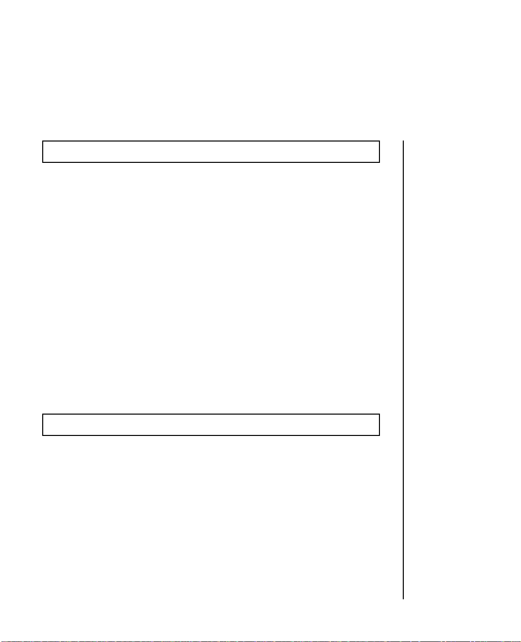
Your new OKI printer is packed in a protective container along with this
manual and some extra items you will need. These items include:
Paper separator
Q
L
N
I
L
I
T
U
0
H
1
H
C
T
I
P
2
1
R
E
W
O
P
7
M
1
R
A
L
A
T
C
E
L
E
S
F
TO
.
T
E
S
M
R
O
F
D
E
E
F
E
N
I
L
D
E
E
F
1. Do not plug in your printer until the following steps have been
completed.
AC cable
Platen knob
(fitted)
E 280
LIN
RO
IC
I M
K
9 PIN PRINTER
O
Y
T
D
S
Ribbon cartridge
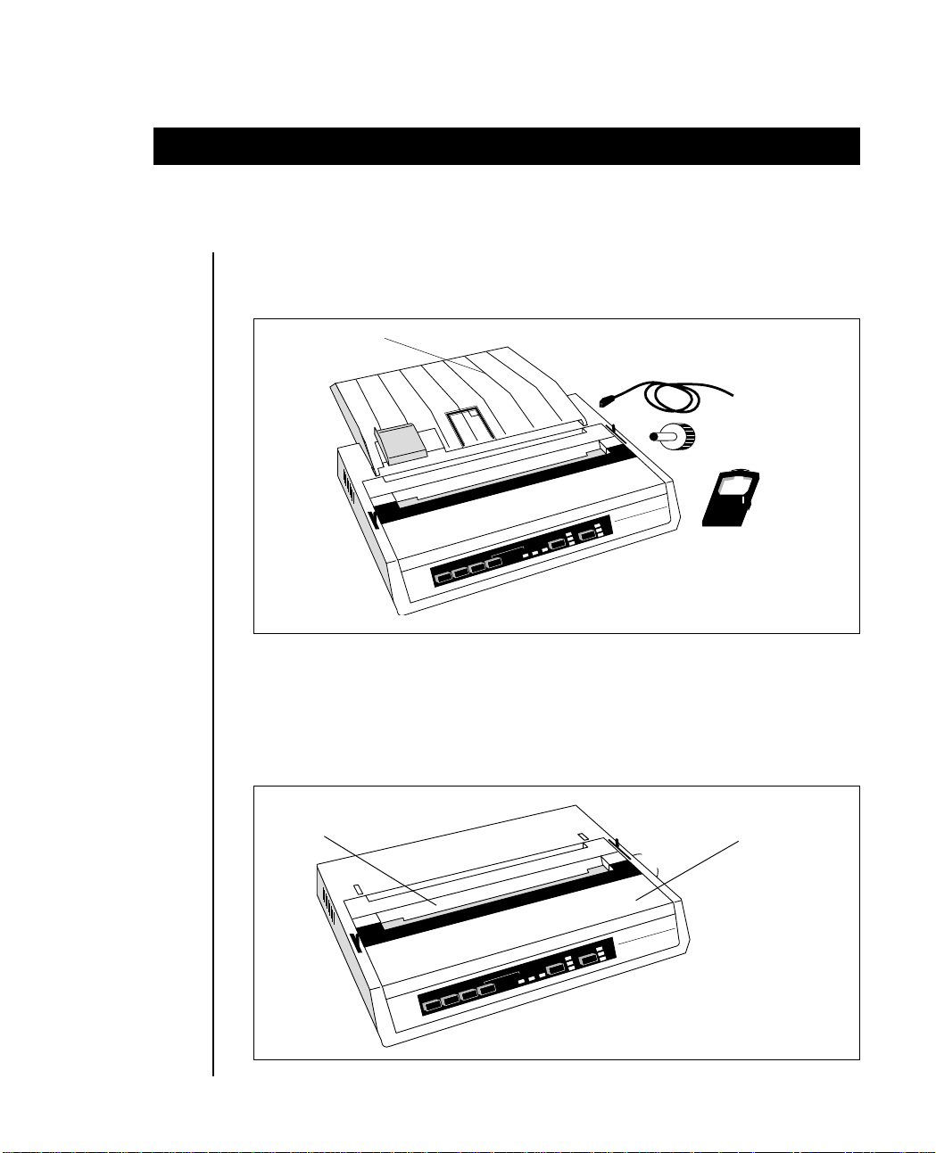
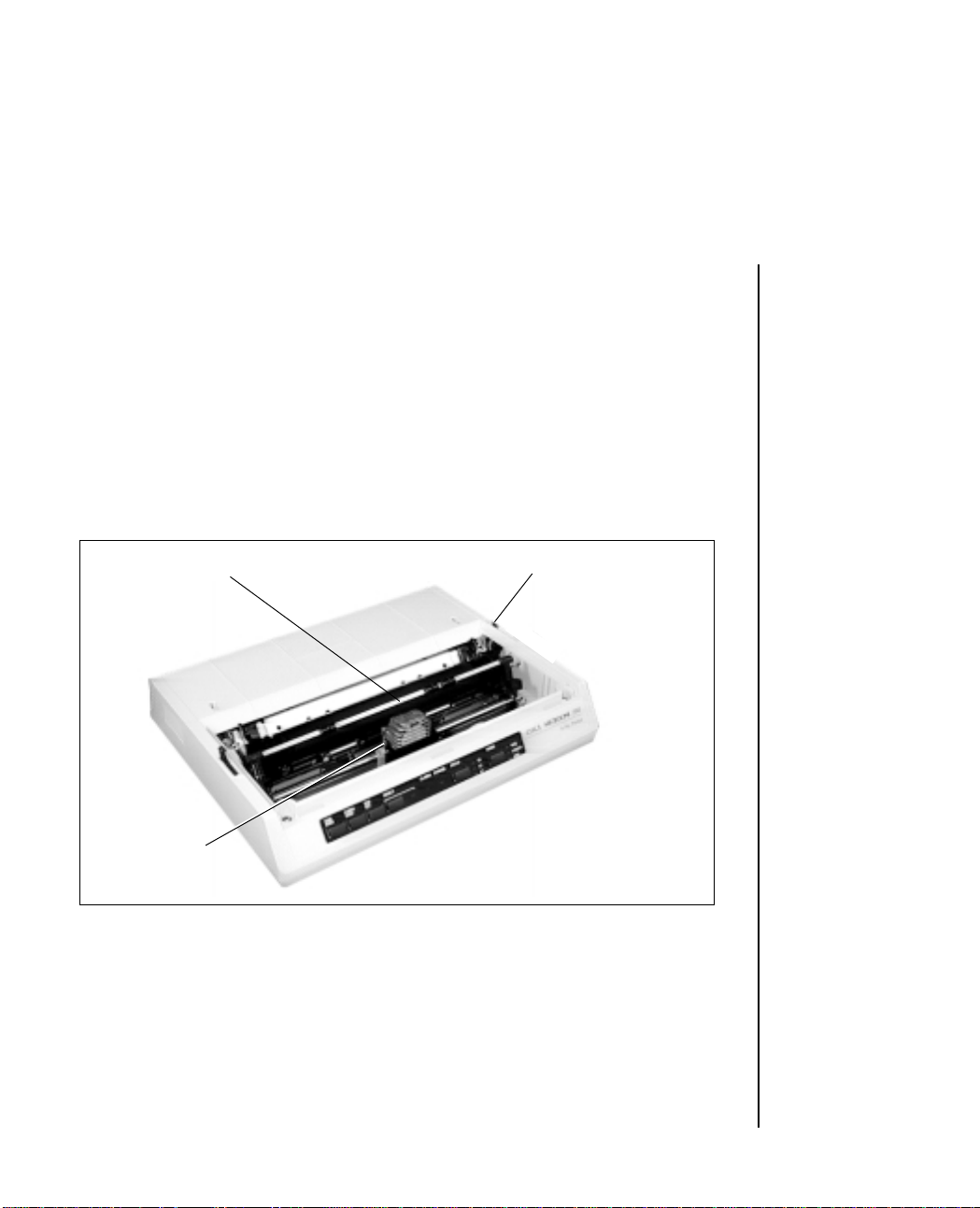
2. Remove the access cover by inserting your hand in the top cover slot
(see figure below) and lifting.
Slot
0
28
E
IN
L
O
R
E
R
T
IN
IC
R
P
I M
IN
K
P
9
O
Q
L
N
Y
T
I
L
I
T
U
D
S
0
H
1
H
C
IT
P
2
1
R
E
W
O
P
7
M
1
R
A
L
A
T
C
E
L
E
S
F
TO
.
T
E
S
M
R
O
F
D
E
E
F
E
IN
L
D
E
E
F
Access cover
Setting Up 1 – 1
Page 6
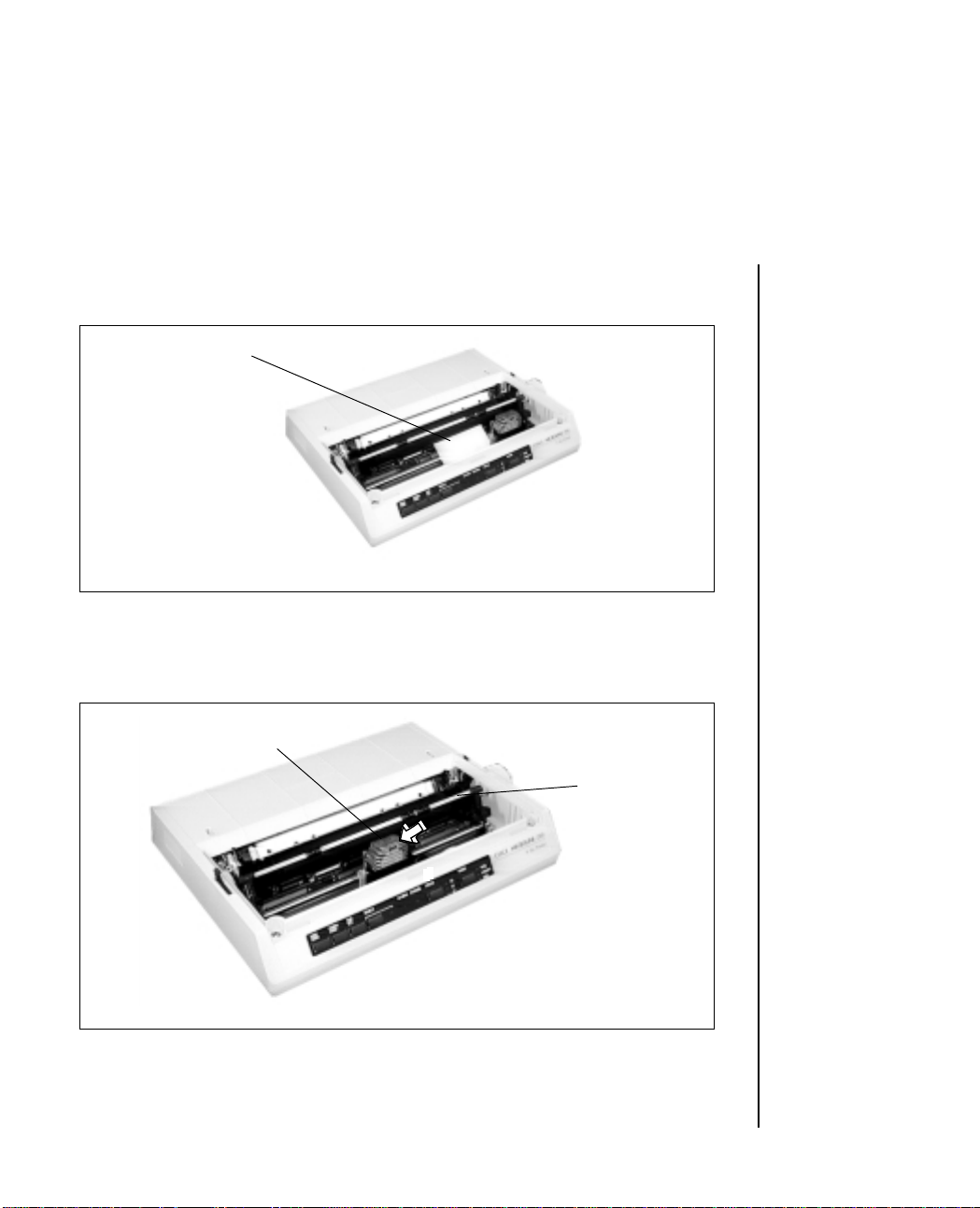
3. Remove the carriage shipping restraint that keeps the print head in
place.
Carriage shipping
restraint
➡
4. Gently slide the print head to the middle of the printer or to the lefthand side so that it is away from the rollers on the column indicator
bar.
Print head
Column
indicator
bar
1 – 2 Setting Up
Page 7
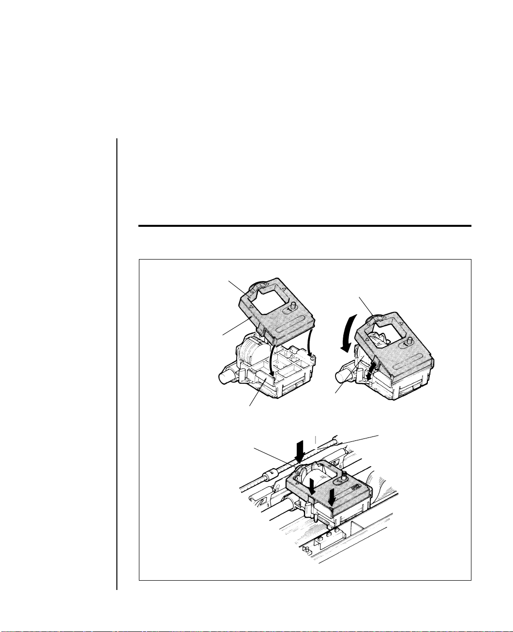
5. Place the black ribbon cartridge on the ribbon cartridge holder. The
easiest method is to tilt the back of the cartridge so that it slides into
the area of the plate that is nearest the front of the printer, then lower
the top of the cartridge (where the plastic ribbon shield is located)
over the print head. The tabs on both sides of the cartridge should
align perfectly with the inserts on the print head plate.
Important: Only use genuine OKI ribbon cartridges in your printer. Do not remove the
ribbon shield.
Ribbon cartridge
Ribbon shield
Holding position
Print head
Ribbon cartridge holder
Ribbon shield
Column indicator
Setting Up 1 – 3
Page 8
6. Press gently on the cartridge until you feel it snap into place. To
remove the ribbon cartridge, make sure the print head is moved
away from the edge of the platen, then grasp the cartridge on both
sides of the print head and lift up.
7. The three-position blue lever located to the left of the ribbon cartridge
is used to adjust the print head gap for single or multi-part paper.
When single part paper or two part paper is in the printer, slide the
blue lever forwards towards the print head. To print on three or four
part paper, slide the lever away from the print head.
Column indicator
bar
Print head gap
lever
Paper release lever
1 – 4 Setting Up
Page 9
8. The platen knob should already be fitted to the right hand side of the
printer. However, if this is not the case, or if it has been removed for
any reason, align its slot with the spigot on the platen shaft.
9. Try running a self test to make sure your new printer is working
correctly. Insert a piece of computer paper (with sprocket holes) or
a single sheet of typing paper into the printer as you would insert it
in a typewriter. If you are unfamiliar with typewriters, here is the
method:
a. Open the paper release lever by sliding it towards you.
b. Insert the paper as far as you can into the slots provided by the
black paper guides.
Paper guides
Setting Up 1 – 5
Page 10

c. Close the paper release lever.
d. Turn the platen knob clockwise away from you to pull the paper
around the platen and behind the column indicator bar.
e. Move the column indicator bar back on to the platen so that the
rollers rest on the paper you have just inserted.
10. Advance the paper, using the platen knob, until 1 inch of paper
appears above the column indicator bar.
11. Replace the access cover:
a. Insert the three tabs in the edge of the access cover into the holes
on the top front edge of the printer.
b. Lower the access cover on to the printer.
12. Grasp the paper and pull it through the opening in the access cover.
Use the platen knob if you need more paper.
13. Insert the connector end of the power cord into the socket at the rear
of the printer.
14. Make absolutely certain that the ON/OFF power switch on the side
of the printer is OFF. (A sudden power surge can damage the
printer.)
15. Plug the power cord into an earthed (three-pronged) electrical
socket.
Important: The printer must be earthed at all times.
1 – 6 Setting Up
Page 11
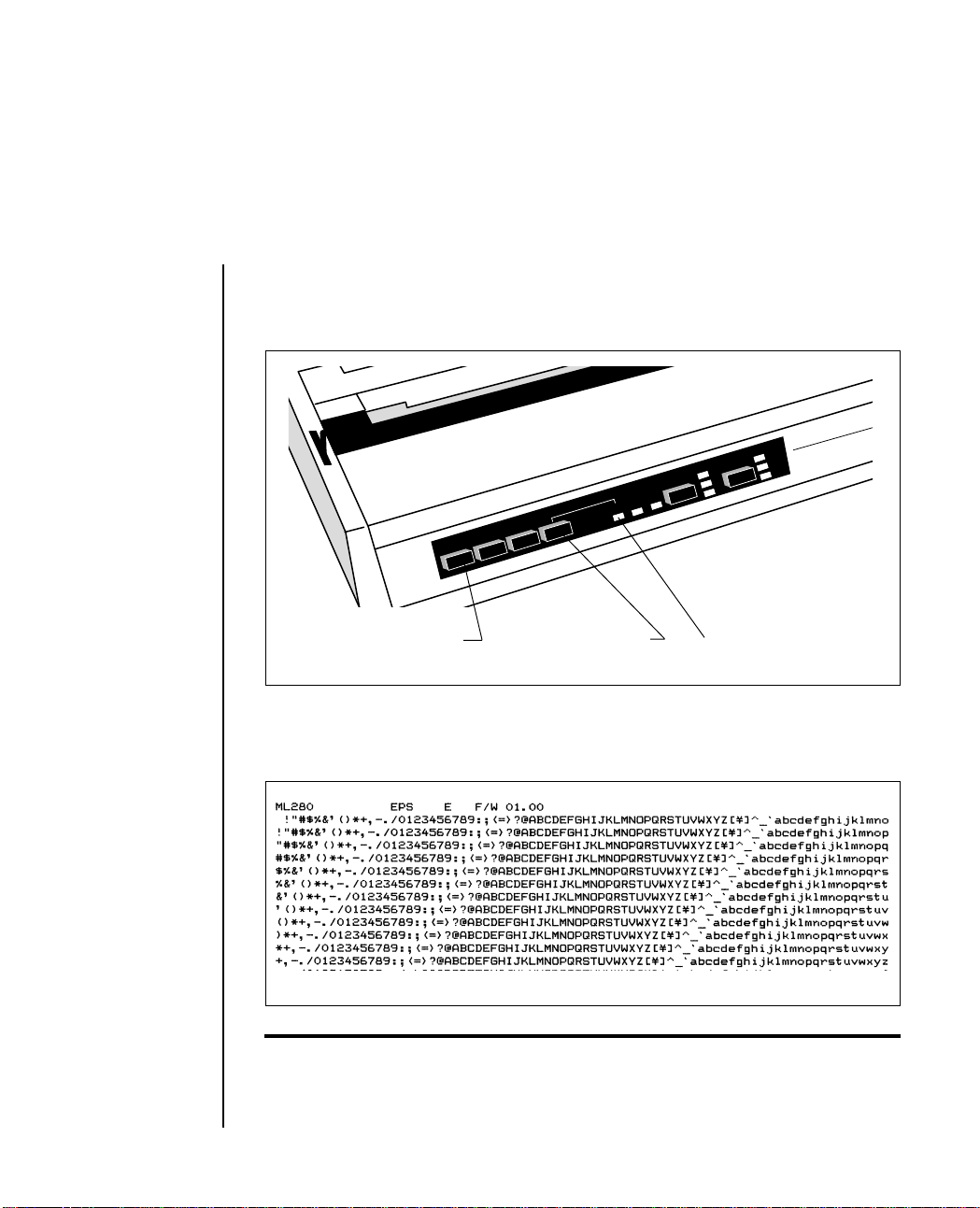
16. To print the self test, hold down the LINE FEED button and turn the
E
PR
power switch ON. When the printer is powered on (indicator
lights), release the LINE FEED button.
9 PIN
Line feed
OKI MICROLIN
NLQ
UTILITY
10
PITCH
POWER
ALARM
SELECT
TOF
SET.
FORM
FEED
LINE
FEED
SELECT button
12
17
SELECT indicator
HSD
17. The following test pattern will be printed, beginning with a printer
revision number that is followed by a rolling character pattern .
4YR4100–7200
Note: During self test printing the SELECT indicator is not lit.
Setting Up 1 – 7
Page 12

18. To stop the test, press the SELECT button or turn the power switch
OFF.
After the printer has shown that it is functioning correctly, it is ready to
be connected to your computer using an interface cable. If you do not
have one, see your computer dealer or, if you have the equipment and
the technical expertise, make your own cable using the instructions in
Appendix C.
1 – 8 Setting Up
Page 13
Connecting to your computer
You will need either a parallel or serial interface cable to connect your
computer to your printer. Before you connect the cable, make sure both
printer and computer power is OFF.
Connecting a Parallel Interface
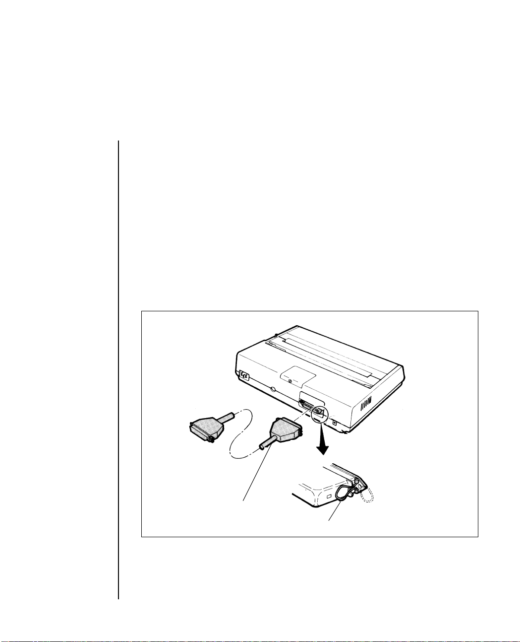
1. Insert the 36-pin plug into the appropriate socket on the rear of the
printer.
Parallel interface cable
Locking tab
Setting Up 1 – 9
Page 14
2. Snap the two wire locking tabs on to the plug.
3. Insert the other end of the cable into your computer. You may also
connect it to another peripheral device, such as a disk drive, if your
equipment is designed for daisy chain connection.
4. Turn on the equipment and try the one line BASIC program shown
below, using the proper print statement for your computer (the
example uses LPRINT). Make sure you have paper and ribbon in the
printer.
5. Type: LPRINT “EVERYTHING’S OKAY” and then run the program.
6. Your printer should print this at 10 characters per inch.
EVERYTHING’S OKAY
Note: If the printer did not print, make sure you entered the program correctly. Some
computers require that you assign a number to the printer and specify that number in
your print statement; for example OPEN # 3 means the printer is on line # 3 to the
computer.
7. Now try this BASIC program (change it, if necessary, to suit your
computer’s requirements):
10 LPRINT “THIS IS LINE ONE”
20 LPRINT “AND THIS IS LINE TWO”
8. The printout should look like this:
THIS IS LINE ONE
AND THIS IS LINE TWO
1 – 10 Setting Up
Page 15

If it is overprinted, make a small adjustment to the printer switch
settings so that a line feed is automatically inserted at the end of a line.
(See Page 1-12 for details.)
Setting Up 1 – 11
Page 16
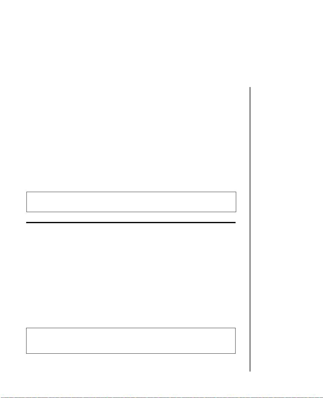
Setting the internal DIP switches
Before altering the settings of the eight DIP switches, please read the
instructions on Page 1-14. These DIP switches are under the small cover
on the top of the printer. They allow the selection of a specific language
and to make the printer meet the requirements of your computer. This
section describes the switches and their factory settings.
Circuit board control
switches
Function switch
access hole
Switch cover
Note: If you have the optional interface board installed, this switch is located on the
lower board.
1 – 12 Setting Up
Page 17
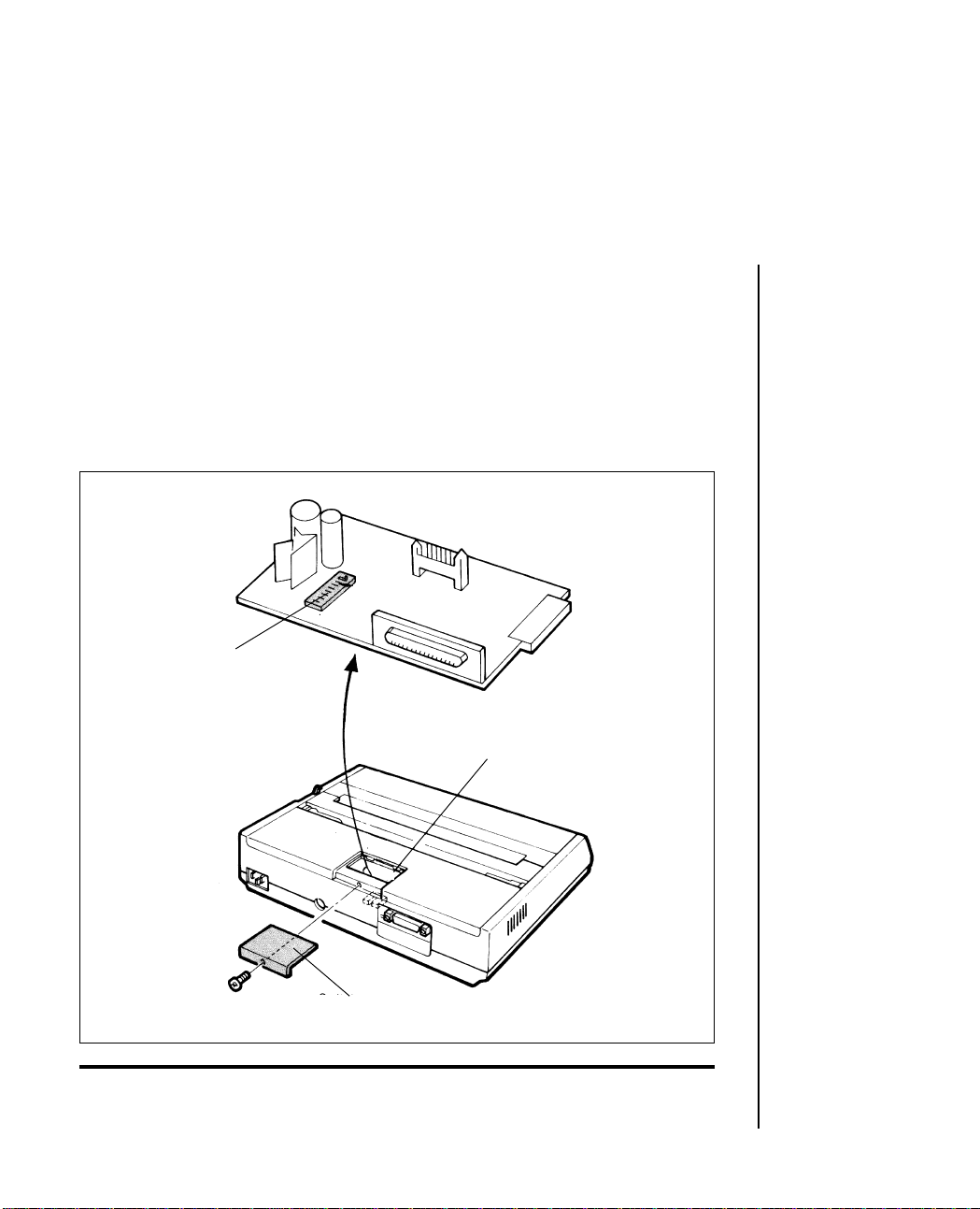
Switches 1 to 5 work in combination to select a foreign language (or
computer character set). The following table shows the correct switch
settings for all available languages.
Language Switch Number Page
Length
1 2 3 4 5 (inches)
USA OFF OFF OFF OFF OFF 12
French ON OFF OFF OFF OFF 12
German OFF ON OFF OFF OFF 12
British ON ON OFF OFF OFF 12
Danish 1 OFF OFF ON OFF OFF 12
Swedish 1 ON OFF ON OFF OFF 12
Italian OFF ON ON OFF OFF 12
Spanish ON ON ON OFF OFF 12
Japanese OFF OFF OFF ON OFF 12
Norwegian ON OFF OFF ON OFF 12
Danish 2 OFF ON OFF ON OFF 12
Dutch ON ON OFF ON OFF 12
Swedish 2 OFF OFF ON ON OFF 12
Swedish 3 ON OFF ON ON OFF 12
Swedish 4 OFF ON ON ON OFF 12
Turkish ON ON ON ON OFF 12
Swiss 1 OFF OFF OFF OFF ON 12
Swiss 2 ON OFF OFF OFF ON 12
USA OFF ON OFF OFF ON 11
French ON ON OFF OFF ON 11
German OFF OFF ON OFF ON 11
British ON OFF ON OFF ON 11
Danish 1 OFF ON ON OFF ON 11
Swedish 1 ON ON ON OFF ON 11
Italian OFF OFF OFF ON ON 11
Spanish ON OFF OFF ON ON 11
Japanese OFF ON OFF ON ON 11
Norwegian ON ON OFF ON ON 11
Danish 2 OFF OFF ON ON ON 11
Dutch ON OFF ON ON ON 11
Swedish 2 OFF ON ON ON ON 11
Swedish 3 ON ON ON ON ON 11
Setting Up 1 – 13
Page 18

It is recommended that you set the printer for the language or character
set you use most. You can use a program command (see Page 3–9) to
change to another language within a document, so it is not necessary to
change these switch settings if you use more than one language.
Switch 6 is the automatic line feed selection. Before shipment, it is set to
OFF. If you discover that your text is being overprinted, it may be
because your computer does not send a line feed at the end of a line. In
that event, set this switch to ON and the printer will insert an automatic
line feed at the end of each line. If your computer automatically sends a
line feed at the end of every line you can use this feature to double space
a document by setting it to the ON position.
Switch 7 selects the slashed or unslashed zero font. The slashed zero font
should be chosen when it is important to distinguish between a zero and
a capital O. The switch is set to OFF to select the unslashed zero and to
ON to select the slashed zero.
Switch 8 selects the roll paper stand (RPS) or the cut-sheet feeder (CSF)
To select the cut-sheet feeder move this switch to the ON position.
Changing the DIP-switch settings
All the switches are set to OFF when the printer leaves the factory.
To reset the switches, proceed as follows:
1 . Make sure the printer is OFF and the power cable is unplugged.
2. Using a Phillips-head screwdriver, remove the screw on the switch
cover at the back of the printer and remove the cover.
3. Use a sharp tipped instrument, such as a ballpoint pen or toothpick,
to slide the appropriate switch(es) to the required new setting.
4. Replace the switch cover and tighten the screw.
1 – 14 Setting Up
Page 19
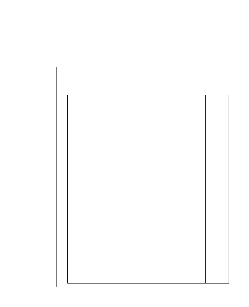
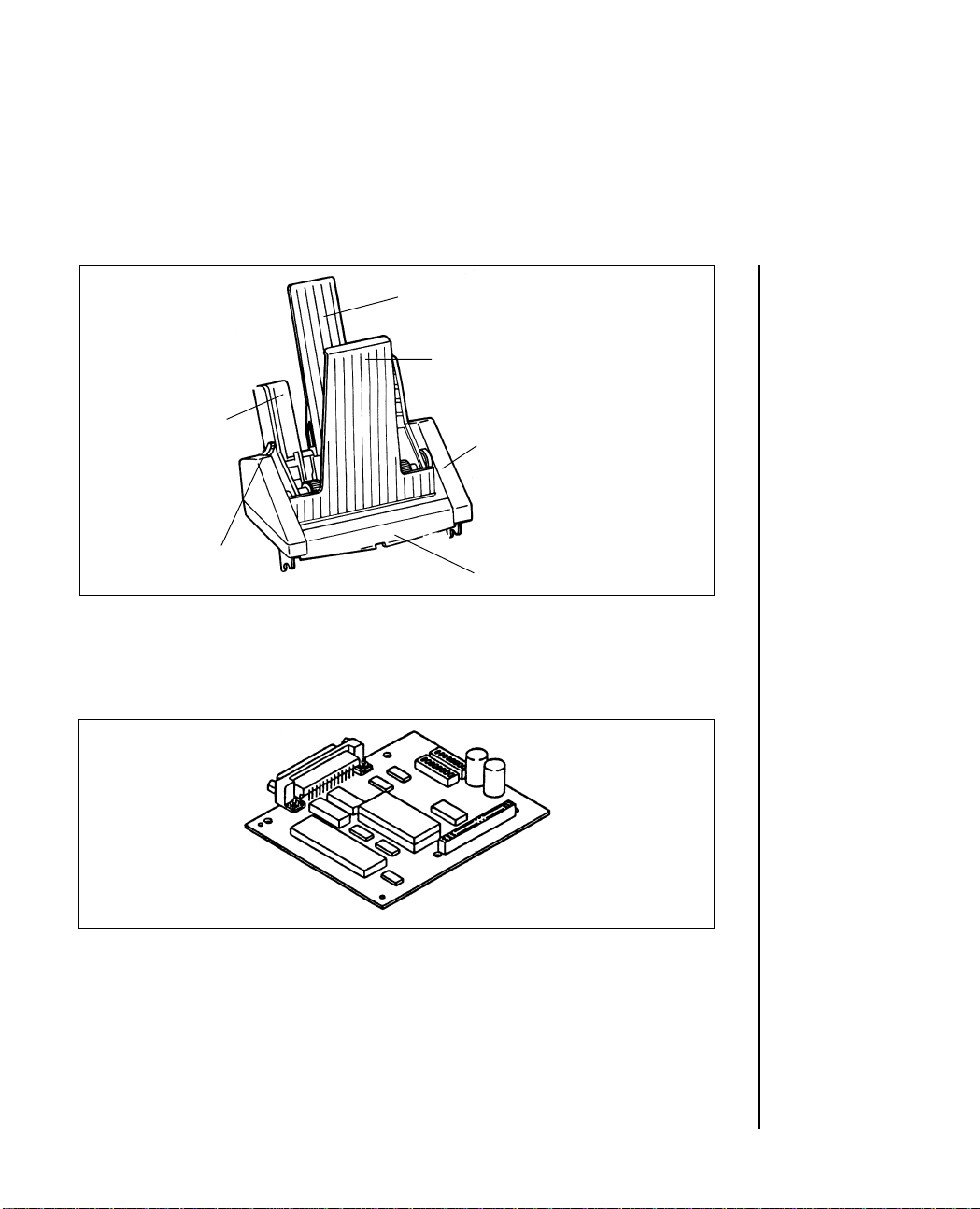
Optional Accessories
Roll paper stand
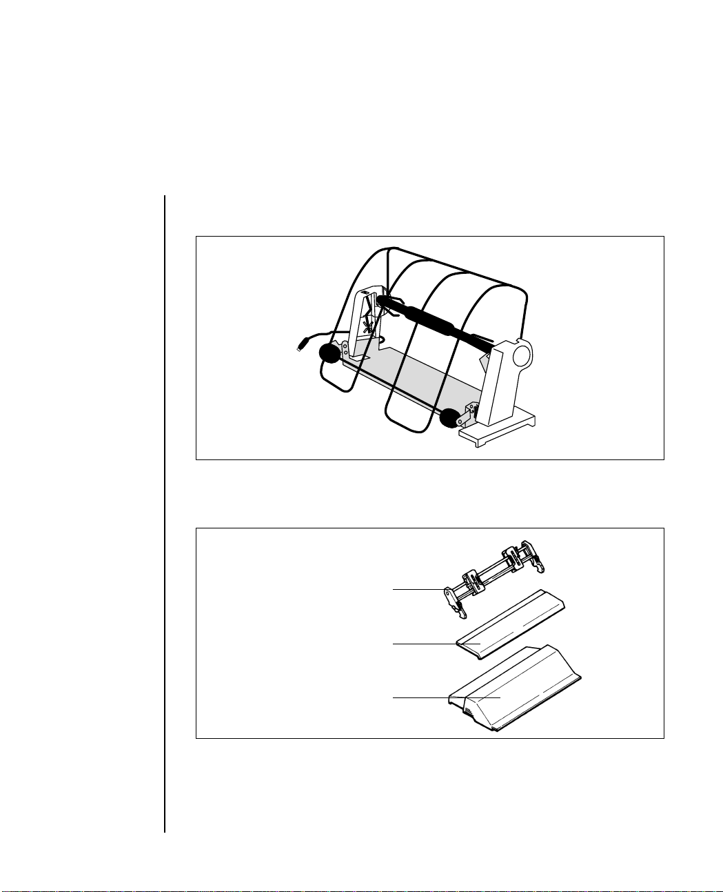
Tractor feed option kit
Tractor feed unit
Access cover
Acoustic cover
Setting Up 1 – 15
Page 20
Cut Sheet Feeder
Left paper guide
Rear sheet support
Front sheet support
Cut-sheet feeder unit
Paper test lever
Interface Equipment
Front sheet guide
RS-232C serial board
1 – 16 Setting Up
Page 21
Chapter 2
Operating Your Printer
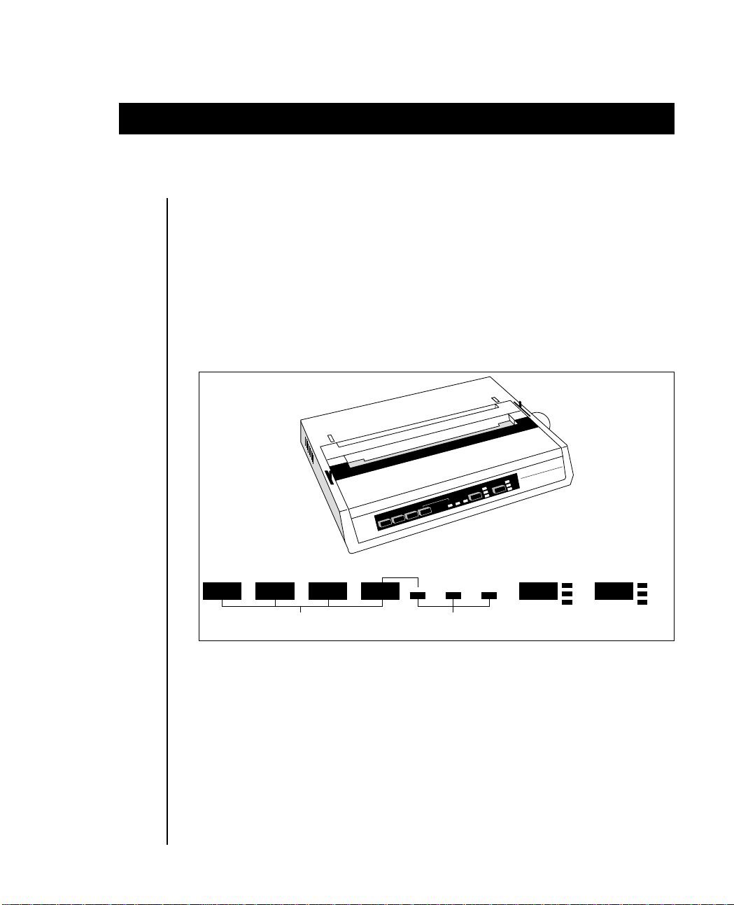
Buttons, levers and indicators
Before using your printer, it is worth familiarising yourself with the
buttons, levers and indicators on the printer and to understand the
various methods of loading paper.
The front panel of the printer has six buttons, two of which were briefly
introduced in the setup procedure. In addition, there are nine indicator
lights that show the status of the printer, mode and pitch selected.
POWER
ALARM
SELECT
TOF
SET.
FORM
FEED
LINE
FEED
R
E
T
IN
R
P
IN
P
9
OKI MICROLINE 280
LQ
N
UTILITY
HSD
10
PITCH
12
17
LINE
FEED
FORM
FEED
TOF
SET
BUTTONS INDICATORS
SELECT
ALARM POWER
PITCH
MODE
10
12
17
NLQ
UTILITY
HSD
POWER Indicator: Indicates that the printer power is turned ON .
SELECT Button: Pressing this button after the printer power is
ON places the printer in deselect mode. In this
mode the computer cannot communicate with
the printer. To return to select mode, simply
press this button again. Turning the printer ON
whilst holding down the SELECT and FORM
FEED buttons switches on the HEX-dump mode.
Operating Your Printer 2 – 1
Page 22
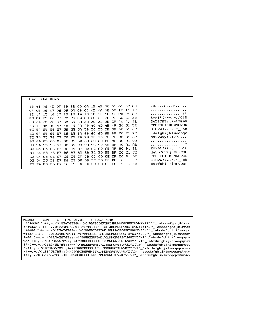
Hex mode generates data rather than text, and a
sample is shown below. To terminate this mode,
switch the printer supply off and on again.
Switching on the printer supply whilst holding
down the SELECT and LINE FEED buttons will
generate a rolling ASCII character display.
Pressing the SELECT button stops this test. A
sample is shown below.
TOF SET Button: To set the first line position on each page (Top of
Form), deselect the printer, hold down the TOF
button and press the FORM FEED to move the
paper up, or the LINE FEED to move the paper
down until the print head is in the desired
position.
2 – 2 Operating Your Printer
Page 23

Release and then press the TOF SET button to
record the position, then reselect the printer by
pressing the SELECT button.
17.1 character per inch can be selected by holding
down the TOF SET button when switching the
printer supply on.
SELECT Indicator: Works together with the SELECT button. Lights
when the printer is selected (ready to receive
data from the computer). It is not lit when the
printer is deselected or during self tests. If an
abnormal status is detected during the self test,
the indicator flashes.
FORM FEED Button: Pressing this button advances the paper to the
top of the next page, as set by the TOF SET
button. NLQ (Near Letter Quality) print can be
selected with this button by holding it down
whilst switching on the printer supply.
ALARM Indicator: Lights when paper runs out (unless the alarm
disable command has been used). Printing stops
until the paper supply is replenished. It also
lights if a jam is detected whilst using the CSF. It
also flashes if high temperatures are detected in
the printhead or space motor. Allow the printer
to cool down before re-using.
LINE FEED Button: Advances the paper one line when the printer is
deselected. A demonstration page illustrating
the print styles available on your printer can be
generated by holding down this button whilst
switching on the printer supply. When the
demonstration page is completed, the printer
will automatically revert to 10 cpi Utility mode.
An example of this printout is on the next page.
Operating Your Printer 2 – 3
Page 24

2 – 4 Operating Your Printer
Page 25

PITCH Button: This button allows manual character pitch
selection. The appropriate lamp lights upon
selection. The lamps also light as software
changes are implemented, for example, normal
to condensed.
MODE Button: Similar function to above, but this refers to the
print quality selected: NLQ, Utility or High
Speed Draft.
The levers on the printer allow you to adjust the paper.
PAPER LOCK/ Open (slide forwards) for inserting paper, and
RELEASE LEVER:
adjusting paper, and when using tractor fed
computer paper. Close (slide back) for use with
roll paper and for single sheets.
PAPER GAP This lever selects the use of fan-fold or single
ADJUSTMENT:
sheet paper, as shown by the symbols at the two
extremities of its slot.
Move the lever to:
for fan-fold paper
for single sheet paper.
Operating Your Printer 2 – 5
Page 26

Paper loading
Three types of paper can be used with your printer:
• Single sheet paper — with/without the optional cut-sheet feeder
• Roll paper — using the optional roll paper stand
• Fan-fold paper — with without the optional tractor feed unit.
Illustrations on the installation and use of the above mentioned optional
extras follow later in this chapter.
When using fanfold paper, adjust the distance between the sprocket
pins at the ends of the platen to correspond to the holes in the paper. See
Page 2-16 for full details.
Fan-fold paper can be fed from the rear of the printer, or, if a slotted
printer stand is available, from the bottom.
Rear Feed Paper Loading:
1. Put the printer on a desk or table.
2. Place the box of paper behind the printer.
3. Remove the access cover and lift the column indicator bar.
4. Open the paper release lever.
5. Insert the first sheet of paper in the paper guides.
6. Push the paper in just enough so that its sprocket holes engage the
sprocket pins located on the platen ends.
2 – 6 Operating Your Printer
Page 27

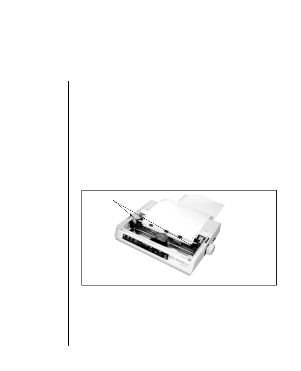
7. Turn the platen knob to advance the paper until it appears in front
of the platen.
Paper guides
Column
indicator
bar
Paper
release
lever
Platen knob
8. Lower the column indicator bar.
9. Use the platen knob to advance the paper to the first printing line.
10. Replace the access cover.
Bottom Feed Paper Loading
1. Place the printer on a slotted printer stand, carefully aligning the slot
in the stand with the opening in the base of the printer.
2. Place the box of paper under the printer stand.
3. Remove the access cover and lift the column indicator bar.
4. Pull the paper release lever towards the fan-fold paper symbol.
5. Insert the first sheet of paper through the opening in the bottom of
the printer.
Operating Your Printer 2 – 7
Page 28

➡
6. Slide the paper up until it appears in front of the platen.
7. Lower the column indicator bar.
8. Use the platen knob to advance the paper to the first printing line.
9. Replace the access cover.
2 – 8 Operating Your Printer
Page 29

Loading single sheets
Your printer can accomodate single sheets of 216 by 297 or 355mm (8.5
by 11-inch or 14-inch) paper. Only one copy, with no carbons, can be
printed at a time.
Remove the tractor feed unit and any other accessories before using the
paper separator.
Operation
1. Place the paper release lever in its closed (rear) position.
2. Switch the printer OFF-LINE (press the SELECT switch).
3. Close the paper bail lever (To its rearward position).
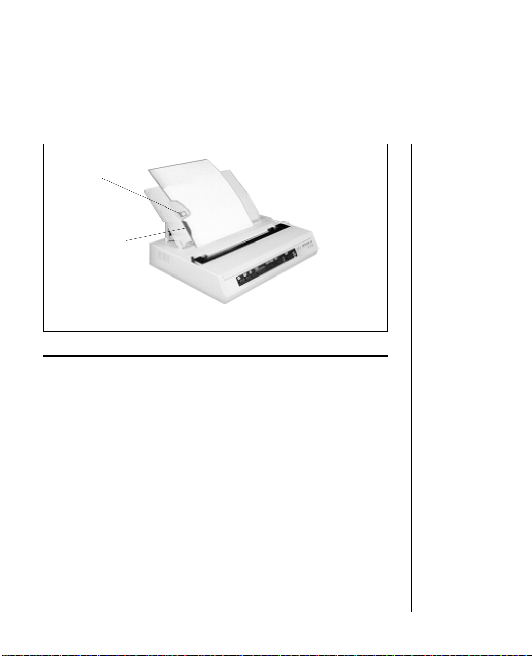
4. Raise the paper separator as shown in the figure below.
5. Adjust the cut sheet guide on the paper separator to position the left
edge of the paper sheet.
Single sheet
Stay
Cut sheet
guide
Paper bail
lever
Paper separator
Operating Your Printer 2 – 9
Page 30
Line mark
Cut sheet guide
NOTE: When letter-size paper is used, set the cut sheet guide to the line mark on the
paper separator. 80-character width text (10 CPI) is then positioned centrally on the
paper.
6. Insert a single sheet along the cut sheet guide until it reaches the
pinch roller. Be sure to keep the paper inside the platen ends
otherwise the built-in sprocket pins will tear it.
7. Open the paper bail lever by pulling it towards the front of the
printer. The sheet of paper will be pulled around the platen.
8. Close the paper bail lever, ensuring that the paper has been positioned
correctly.
9. Press the SELECT button to bring the printer ON-LINE.
2 – 10 Operating Your Printer
Page 31

Chapter 3
Programming
Now that you are familiar with the outside of the printer, you can begin
printing documents using the default settings of the printer, that is, the
kind of printing your printer is set up to do when you turn it on:
Utility Mode*
10 characters per inch
6 Lines per inch
Horizontal tabs at every eighth character
Vertical tabs at one inch intervals
This may be all you ever need.
If you plan to print tables, charts, graphics, or documents with indented
text, subscripts, superscripts, etc., you should read this chapter to learn
how and when to use the special printing features.
First, here are the available printing options:
Carriage Return: If your computer does not automatically
add a carriage return at the end of a line,
you may add one to your program.
Unidirectional Printing: With this method, characters are printed
from left to right, which is useful for tables
and charts where accuracy is important.
Horizontal Tabs: Sets tabs at predetermined intervals;
perfect for accounting reports, tables, and
charts.
Line Spacing: Gives you a choice of 6 or 8 lines per inch.
Formatting: Adjusts printing to a particular paper size,
controls the line where printing begins,
and automatically advances the paper
when less than 1 inch remains at the bottom
of a page. See skip over perforation
function.
* NLQ mode will be selected by pushing the FORM FEED switch during power-up.
Programming 3 – 1
Page 32

Skip Over Perforation: If you use fanfold paper with your printer,
you may need to use this command to
instruct the printer to automatically
advance the paper over the perforations.
Character Pitch: You can change from 10 to 12 or 17.1
characters per inch and you can also double
the character width (10 characters per inch
to 5 characters per inch, 12 characters per
inch to 6 characters per inch and 17.1
characters per inch to 8.5 characters per
inch).
Enhanced/Emphasized: Prints characters in a bolder type,
commonly used for titles and subtitles.
Underlining: Underlines a word or group of words.
Character Sets: Choose from two different character sets;
IBM character set one or two is selectable.
There is also a switch selection which
enables you to power up the printer in
either set and to establish the default
character set.
APA Graphics: Enables you to draw graphs, charts, and
pictures.
Cancel: Clears the data in the print buffer.
What you do next depends on whether you have invested in a software
package. If you have, skip to page 3-17 for advice on how to add these
features to your prepackaged software. If you do not have a software
package, continue reading.
3 – 2 Programming
Page 33

The printer will not do certain things unless you specifically tell it to. You
instruct the printer to change the way it prints by sending special codes
through your computer. When you write a program, you include the
codes for printing features you want in your program. In BASIC, for
example, include them in an LPRINT statement.
Basic Programming
If you are familiar with programming, skip this section and go straight
to the control codes.
Although we wrote our examples in Microsoft’s BASIC programming
language, the principles are similar for other languages. The examples
demonstrate how to select a few of your printer’s special features and try
them. Later the features are explained in detail.
An LPRINT statement, or print statement, tells the computer to send
information to the printer. Take a minute to check your BASIC manual
to find out what form this takes in your version of BASIC.
Make sure your printer is ready to print (ribbon in, paper loaded, power
ON, SEL indicator lit) and experiment a little with the print commands.
Type the following one-line program:
LPRINT “WHO YOU GONNA CALL?”
2. Press RUN, then RETURN or CR.
3. The printer will then print:
WHO YOU GONNA CALL?
Programming 3 – 3
Page 34

Computers cannot understand letters. They use only numbers, more
specifically, binary numbers (1s and 0s). When carrying out an LPRINT
command, the computer sends the printer a code number for each
character (letter, symbol, punctuation mark) within the quotation marks.
As the printer receives each number, it prints the dot pattern associated
with that number.
The American Standard Code for Information Interchange (better known
as ASCII) is the standard code used by computers. Appendix D gives the
ASCII code numbers along with their hexadecimal, binary, and decimal
equivalents. You can enter these ASCII numbers directly in your LPRINT
statement by using the CHR$ (Character String) function.
The CHR$ command sends the ASCII command in parentheses to the
printer. For example, we can write a program this way:
LPRINT CHR$(79);CHR$(75);CHR$(73)
This is obviously a tedious way to write, but you need to understand the
concept when you want to use certain commands.
Keep in mind that there is a big difference between ASCII code numbers
and numbers that are printable characters. For example, if you want to
print the number 1 using an LPRINT statement, you would type this:
LPRINT CHR$(49)
You can also print numbers and symbols by putting them within quotes,
like this:
LPRINT “1”
So far, we have discussed printable characters, ASCII codes located
between decimal 32 and decimal 127. Non-printable codes, located
between 0 and 31, do not tell the printer to print something. They
instruct the printer how to print something. The ASCII chart in the back
of this handbook shows that these codes have abbreviations, such as FF
and US. Some of these abbreviations make sense (FF, for instance,
stands for form feed) but others do not unless you are a
telecommunications expert.
3 – 4 Programming
Page 35
Let us try a few, starting with the ASCII non-printable code US. When
the printer receives the SO command, it will print the next data with
double width.
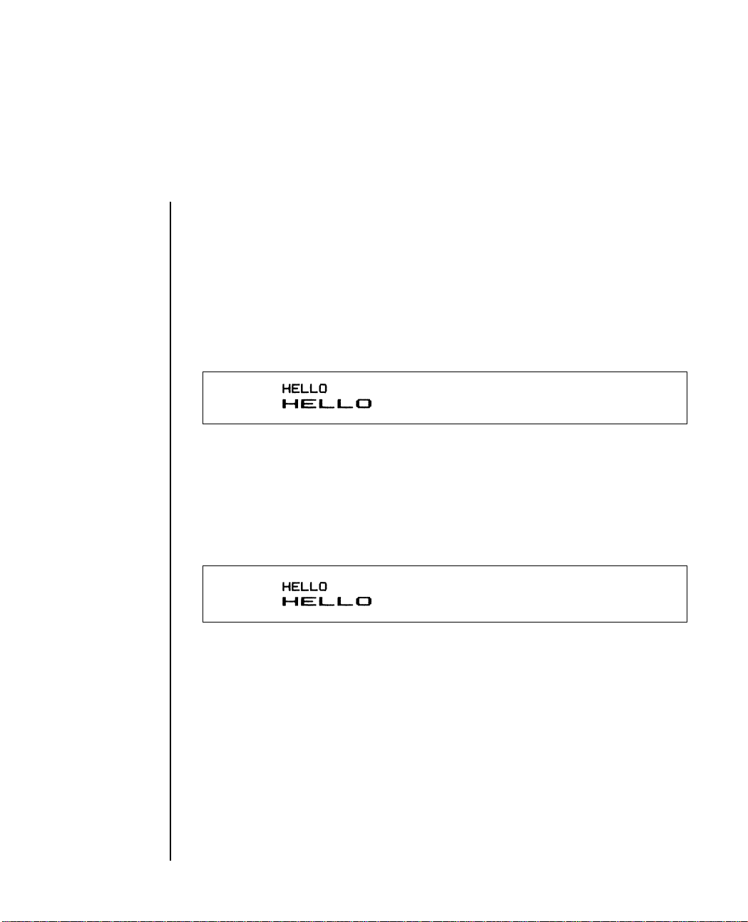
10 LPRINT “HELLO”
20 LPRINT CHR$(14); “HELLO”
Now run the program. This is what you should get:
ASCII code SO is non-printable, so you must use the decimal or
hexadecimal form of the command within a CHR$ statement. Nothing
in quotes will work. Like most commands that change the way the
printer is printing, the SO (double width) command remains in effect
until either the end of a line is reached or you send a command to cancel
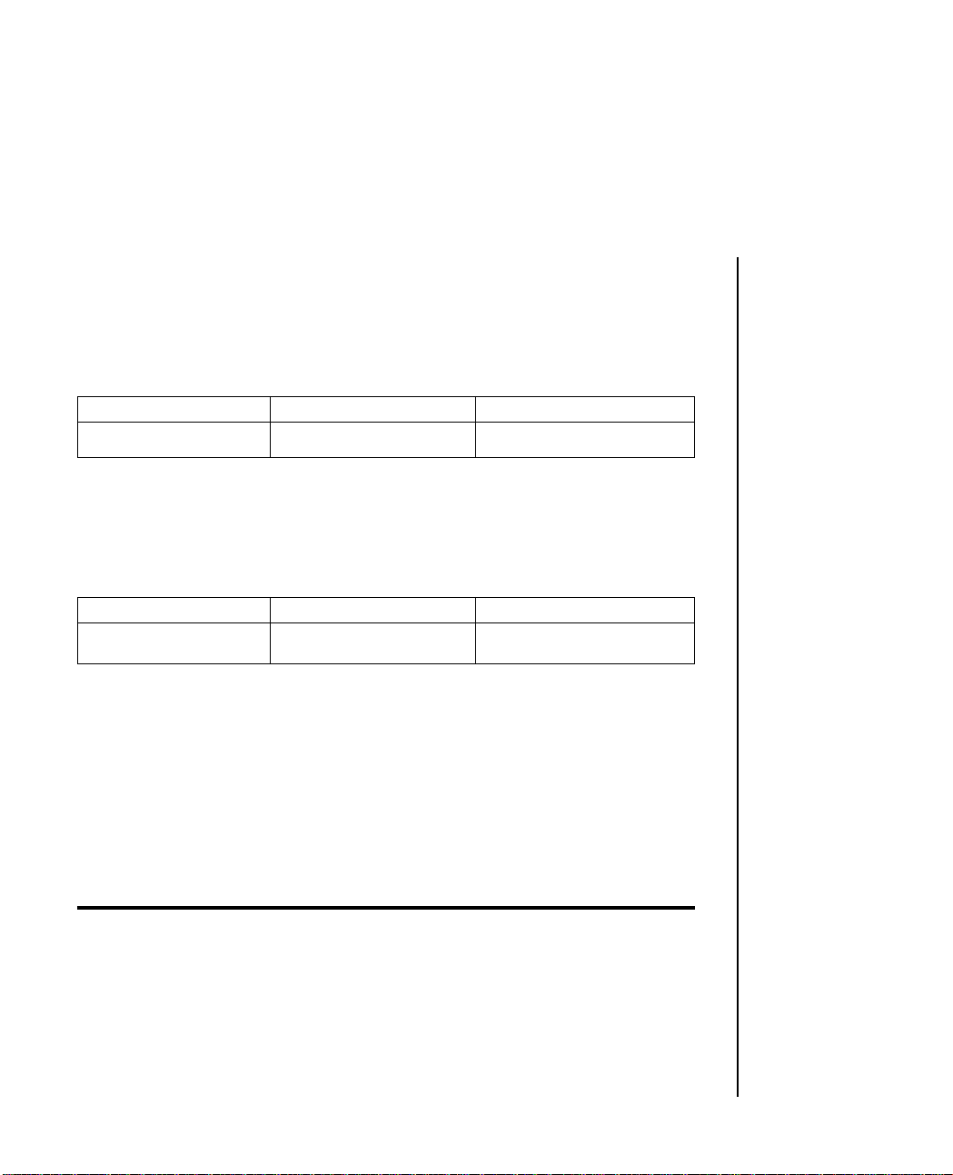
it. See what happens if you run the sample program a second time:
Programming 3 – 5
Page 36

The second time, the first line is printed standard width. Because the SO
command is not in effect by the end of a line. To return to standard size
printing (10 characters per inch) you have to put in CHR$(20), like this:
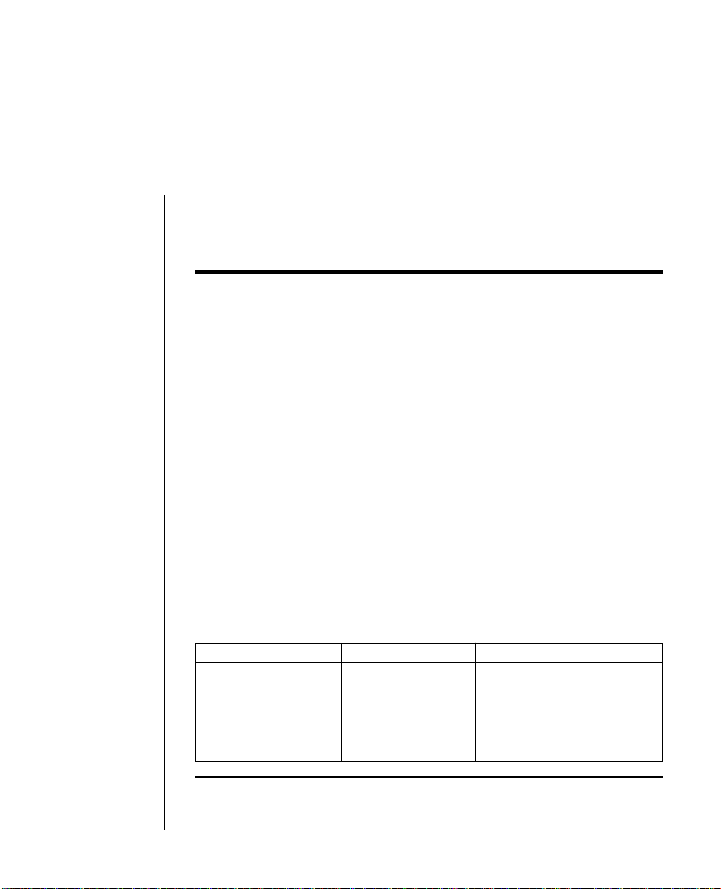
10 LPRINT“HELLO”
20 LPRINT CHR$(14);“HELLO”;CHR$(20); “ _ _ _ HELLO AGAIN”
Note: _ means space.
That is what you should get:
To avoid any unpleasant surprises, you may want to insert codes at the
end of a document to cancel whichever feature(s) you selected and to
reset the printer to the normal start-up condition.
3 – 6 Programming
Page 37

If you have a Software Package
Software packages make the printer’s special features, such as smaller
type fonts, subscripts, underlining, etc., much easier to use. To add the
features to your package, read your software documentation for
instructions, paying particular attention to any limitations—for example,
some software packages let you select a printing feature for an entire
document but do not allow you to change features within a document.
Other packages may not accept the page formatting commands, such as
horizontal tabs, which are available with your printer.
When you install your package, you probably need to select the features
you are going to be using from a list called a menu. Several software
packages actually list names of printers on the menu, so that all you need
to do is select the IBM Graphic printer from that list—the software
package will then automatically use the commands for your printer. If
they are not on the menu, pick the closest general description; “Teletype
printer that does not backspace” is often the best.
With some software packages, such as WordStar, you can easily modify
or install your program to accept your printer’s commands by inserting
codes into the program. Still other packages let you embed commands
within a document itself by preceding the command with “/OUT” or
something similar. VisiCalc is a popular package that provides a setup
option as part of the printing procedure—you simply specify at the
beginning of a document what printing features you will be using.
Programming 3 – 7
Page 38

If your computer is equipped with BASIC, you have an alternative to
selecting features. After you load BASIC, run a simple one or two line
program telling the printer to change a feature(s).
Without turning the printer off, load and run your software package.
For example, suppose you wanted to print at 12 characters per inch:
1. Load BASIC
2. Type the command: LPRINT CHR$(27);CHR$(58)
Note: You do not have to know how to program to do this, but be sure to check your
computer documentation to see what statement to use (we use LPRINT) before each
command. Not all versions of BASIC are the same.
3. Press RUN, then RETURN or CR.
4. Without turning the printer off, enter your software package.
What you have just typed causes the computer to send a command to the
printer to go into 12 characters per inch mode. When you load and run
your software, all printing thereafter will be at 12 characters per inch
until you turn the printer off or send a command to change the characters
per inch setting.
There is one exception to this method, however: You cannot use this
method if your computer sends an I-Prime signal before you load a
program. An I-Prime signal is sent by some computers to cancel any
special commands that were previously in effect so that you can start
fresh with each new document.
3 – 8 Programming
Page 39

Programming the printer
For each printing feature explained in this chapter, three different forms
of each code are listed as follows:
ASCII Decimal Hexadecimal
ESC 1 27 49 1B 31
Standard abbreviation Standard presentation Hexadecimal code used by
in ASCII-used for of Decimal Code. A some software packages to
reference variation of the same enter printing commands.
command is A variation of the same
CHR$(27);CHR$(49) command is CHR$(&H1B);
CHR$(&H31)
Carriage return and line feed
ASCII Decimal Hexadecimal
CR 13 0D
Carriage return tells the printer to print the line of data and returns the
print head to the left side of the page. IBM PC adds a line feed after a
carriage return unless 128 is added to the command. If you send a
CHR$(141), therefore the result is just a carriage return; for IBM SET 1
only.
ASCII Decimal Hexadecimal
LF10 0A
VT 11 0B
Line feed advances the paper one line; line spacing is 1/6 inch unless it
is reset.
Programming 3 – 9
Page 40

Horizontal Tabulation
ASCII Decimal Hexadecimal
ESC D 0 27 68 0 1B 44 00
Horizontal tabs are set at every 8th character when power is first
switched ON. To eliminate the tab settings, use the ESC D 0 command.
Horizontal Tabbing
ASCII Decimal Hexadecimal
HT 9 09
Advances to the next tab position which occurs every 8th character. The
command is ignored if it exceeds the right margin or the maximum
number of settings.
20 LPRINT “TAB”;
30 LPRINT CHR$(9);“TAB AGAIN”
3 – 10 Programming
Page 41

Line Spacing
The default line spacing for the printer is 6 lines per inch. This means that
when the printer power is turned on, the spacing from the bottom of one
line to the bottom of the next line on the same page is automatically set
to 1/6 inch. This is also the normal spacing of a standard typewriter.
The line spacing can be changed to 8 lines per inch to fit more lines of
printing per page, and for special effects, you can also vary line spacing
in multiples of 1/72 or 1/126 inch. This affects space between lines only,
not the height of the characters.
ASCII Decimal Hexadecimal
ESC 0 27 48 1B 30
The ESC 0 command sets line spacing to 1/8 inch.
ASCII Decimal Hexadecimal
ESC 1 27 49 1B 31
The ESC 1 command sets line spacing to 7/72 inch.
ASCII Decimal Hexadecimal
ESC A n 27 65 1-85 1B 41 01-55
The ESC A command is a user-selectable line space setting that enables
you to choose a setting in increments of 1/72 inch. You can select a
maximum line space setting of 85/72 inches, which is the equivalent of
one printed line every 1-13/72 inches.
ASCII Decimal Hexadecimal
ESC 2 27 50 1B 32
Programming 3 – 11
Page 42
The ESC 2 command implements the line spacing set by the ESC A
command. Should no ESC A command precede the ESC 2 command, the
default line spacing (6 LPI) will be activated by the ESC 2 command.
Fine Line Spacing
ASCII Decimal Hexadecimal
ESC 3 n 27 51 1-255 1B 33 01-FF
The ESC 3 command is a user-selectable line space setting command that
lets you choose a setting in increments of 1/216 inch. You can select a
maximum line space setting of 255/216 inches, which is the equivalent
of one printed line every 1-39/216 inches. (See Note).
ASCII Decimal Hexadecimal
ESC J n 27 74 1-255 1B 4A 01-FF
The ESC J command allows you to interrupt the set line spacing and reset
the line spacing for a single line to a multiple of 1/216 inch. You can select
a maximum space setting of 255/216 inches, which is the equivalent of
a 1-39/216 inches line space. Upon receipt of the ESC J command, the
printer prints out the line containing the command and advances the
paper the distance specified by the command. Line spacing then returns
to the previous setting, and the printer continues to print. (See Note).
Note: (For ESC 3 and ESC J) The standard IBM printer advance is expressed in multiples
of 1/216 inch. IBM-compatible MICROLINE hardware performs paper advances in
multiples of 1/144 inch rather than 1/216 inch; therefore, MICROLINE software
automatically multiplies the number specified in ESC 3 and ESC J statements by 2/3 to
perform the most precise IBM emulation.
3 – 12 Programming
Page 43

If the multiples specified in your ESC 3 or ESC J statements are not evenly
divisible by 3, fine line spacing may be slightly more or slightly less than
you specified. If the number you selected leaves a remainder of 1 when
it is divided by 3, spacing will be slightly less than specified. If the
number you selected leaves a remainder of 2, spacing will be slightly
more than specified. When the number you select is evenly divisible by
3, fine line spacing is always exact.
The ESC A line spacing selection, which selects line spacing in multiples
of 1/72 inch, is always accurate.
Page Length Setting
ASCII Decimal Hexadecimal
ESC C n (in lines) 27 67 1-127 1B 43 01-7F
ESC C NUL n (in inches) 27 67 0 1-22 1B 43 00 01-16
The printer page length set is user selectable in either inch or line
increments where n is either a two or three digit number. Selectable line
length settings range between 1 to 127; selectable inch length settings
range between 1 to 22. The line length default setting is 66 lines per page
(11 inches) with a 6 LPI line spacing. You can also set page length using
the internal switch setting.
Top of Page
ASCII Decimal Hexadecimal
ESC 4 27 52 1B 34
The top margin on a page can be set by issuing this command.
Wherever the print head is at the time this command is given will be the
first printing line. You can also set the top of page using the TOF switch
on the outside panel.
Programming 3 – 13
Page 44

Form Feed
ASCII Decimal Hexadecimal
FF 12 0C
Prints the data in the print buffer, returns the carriage, then advances the
paper to the top margin of the next page.
Note: (TRS-80 owners only.) This command is not valid with your computer.
Skip Over Perforation
ASCII Decimal Hexadecimal
ESC N n 27 78 n (n = 1-127) 1B 4E n (n= 01-7F)
ESC O 27 79 1B 4F
If n is any value between 1 and 127, the printer automatically advances
to the top margin of the next page when there is only 1 inch left at the
bottom of a page. (This command is ignored if the value of n is more than
page length.)
In order to deselect Skip Over Perforations use the command ESC O. In
BASIC format, the value of n must appear in a CHR$ statement.
Changing Character Size
ASCII Decimal Hexadecimal
DC2 (10 CPI) 18 12
ESC : (12 CPI) 27 58 1B 3A
SI (17.1 CPI) 15 0F
SO (double width) 14 0E
DC4 (cancels double 20 14
width before line end)
ESC W 1 27 87 49 1B 57 31
ESC W 0 27 87 48 1B 57 30
3 – 14 Programming
Page 45
The character size switches to 10 characters per inch (CPI) after the
printer receives the DC2 command. The character size becomes 12 CPI
when the ESC: command is received and 17.1 CPI when the SI command
is received.
Note: When the power is turned on while the TOF switch is depressed, the printer is set
to 17.1 CPI. You can also set the printer to 17.1 CPI at power ON by setting internal switch
2 to the condensed print mode. The printer will print in 17.1 CPI until power is turned
OFF or a command is sent to change the character size.
You can double the width of 10, 12, and 17.1CPI print by inserting the
US command after the character size you want doubled. This command
doubles the size of characters that follow the command on one line. The
DC4 command can also be implemented on the same line as an SO
command. The DC4 command cancels double width printing before the
end of a line. This enables you to emphasize specific words or characters
within a single line, and to automatically return to your preselected type
size.
The ESC W 1 and ESC W 0 commands override both DC4 and SO
commands, and can be utilized to either permanently implement or
cancel double-width printing within a program or document. The ESC
W 1 command implements double-width printing; the ESC W 0 command
cancels it.
Character size can be changed in the middle of a line unless your
software package does not allow you to do that. The table below
indicates the maximum number of characters per line in each character
size:
Size Command Maximum Characters per line
10 CPI DC2 80
12 CPI ESC : 96
17.1 CPI SI 132
5 CPI DC2 SO 40
6 CPI ESC : SO 48
8.5 CPI SI SO 66
Note: Some forms of BASIC will not allow you to print more than 80 characters on a line.
Check your BASIC manual to see if you can override this limitation by using a WIDTH
statement.
Programming 3 – 15
Page 46

10 LPRINT CHR$(18);“PICA pica 10 cpi”
20 LPRINT CHR$(27);CHR$(58);“ELITE elite 12 cpi”
30 LPRINT CHR$(15);“CONDENSED condensed 17 cpi”
40 LPRINT CHR$(18);“Back to 10 cpi”
50 LPRINT CHR$(14);“Double pica”
60 LPRINT CHR$(27);CHR$(58);CHR$(14);“Double elite”
70 LPRINT CHR$(15);CHR$(14);“Double condensed”
Underlining
ASCII Decimal Hexadecimal
ESC - 1 27 45 49 1B 2D 31
(n: odd)
ESC - 27 45 48 1B 2D 30
(n: even)
Use the ESC - command to start underlining a word or group of words.
Use the ESC - command to stop underlining. The printer will continue
to underline until the command is given to stop it (either ESC - 0, or the
printer is powered down). (Because the underline is drawn by the ninth
dot, the last dot in some descender characters will be overlapped.)
3 – 16 Programming
Page 47
Underlining under the spaces designated by horizontal tabs is also
available.
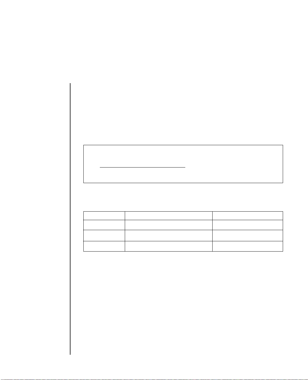
10 LPRINT “This line is not underlined”
20 LPRINT CHR$(27);“-”;CHR$(1);“but this line is underlined”
30 LPRINT CHR$(27);“-”;CHR$(0);“This line is not underlined”
This is not underlined
but this is underlined
This line is not underlined
Superscript and Subscript
ASCII Decimal Hexadecimal
ESC S 0 27 83 48 1B 53 30
ESC S 1 27 83 49 1B 53 31
ESC T 27 84 1B 54
If you want to print superscript characters (characters appearing above
the normal print line), send the ESC S 0 command before the characters,
symbols, or word(s) you want printed in superscript. To return to
printing on the normal print line, use the ESC T command.
Programming 3 – 17
Page 48

If you want to print subscript characters (characters appearing below the
normal print line), use the ESC S1 command before entering the characters.
To return to printing on the normal print line, use the ESC T command.
Superscript and subscript characters are printed in normal characters.
10 LPRINT “This is ”;
20 LPRINT CHR$(27);“S”;CHR$(0);“superscript”
30 LPRINT CHR$(27);“T”;“This is ”;
40 LPRINT CHR$(27);“S”;CHR$(1);“subscript”
50 LPRINT CHR$(27);“T”;“This is back to normal.”
This is
This is
superscript
subscript
This is back to normal
Enhanced and Emphasized Printing
ASCII Decimal Hexadecimal
ESC E 27 69 1B 45
ESC F 27 70 1B 46
ESC G 27 71 1B 47
ESC H 27 72 1B 48
3 – 18 Programming
Page 49

Enhanced printing provides a deeper resolution of each character because
each dot contained in a normal character is doubled vertically, creating
a darker impression. The ESC G command is a good feature to use for
headlines and subtitles and can be used in conjunction with doublewidth characters.
Emphasized printing, obtained by entering the ESC E command, causes
each character to be doubled horizontally, creating a bolder image for
titles, subtitles, or emphasizing word(s) within a document.
To return to the normal character set from emphasized mode, enter the
ESC F command. To return to the normal character set from enhanced
mode, enter the ESC H command. Neither feature is available for
subscripts or superscript characters nor in line graphics.
Emphasized and enhanced printing can also be done simultaneously for
special effects.
10 LPRINT CHR$(27);CHR$(71);“ENHANCED”
15 LPRINT CHR$(27);CHR$(72)
20 LPRINT CHR$(27);CHR$(69);“EMPHASIZED”
25 LPRINT CHR$(27);CHR$(70)
30 LPRINT CHR$(27);CHR$(71);CHR$(27);CHR$(69);
“ENHANCED/EMPHASIZED”
35 LPRINT CHR$(27);CHR$(72);CHR$(27);CHR$(70)
Programming 3 – 19
Page 50

Character Sets
ASCII Decimal Hexadecimal Character Set
ESC 6 27 54 1B 36 II
ESC 7 27 55 1B 37 I
If you use Spanish for all your documents it is better to make the selection
on the internal switches so that the printer normally uses that language.
Cut Sheet Feeder
ASCII Decimal Hexadecimal
ESC EM I 27 25 73 1B 19 49
ESC EM R 27 25 82 1B 19 52
If you are printing program outputs using the Cut-Sheet Feeder, you
must include the Cut-Sheet Feeder insert and eject commands. When the
printer receives the PRINT command, it inserts a sheet of paper and
starts printing. Each time the printer receives the Cut-Sheet Feeder insert
command, it ejects the printed sheet then inserts a new sheet. Use the
Cut-Sheet Feeder eject command at the end of your program if you want
the printer to eject the printed sheet without inserting a new sheet.
You can use the CHR$(27); CHR$(25); “I” command to insert a new sheet
of paper from the hopper. If paper is already in the printer this sheet will
be ejected first before the new sheet is fed in. (In normal use this is
achieved by using the FF code).
Should you wish to eject a sheet then use the CHR$(27); CHR$(25); “R”
command.
Note: A LF command at the end of a page also causes the next sheet to be loaded.
3 – 20 Programming
Page 51

Bit Image Graphics
ASCII Decimal Hexadecimal
ESC K 27 75 1B 4B
ESC L 27 76 1B 4C
ESC Y 27 89 1B 59
ESC Z 27 90 1B 5A
Using bit image graphics, you can draw almost any kind of illustration
with your printer.
Bit image graphics mode enables your printer to draw almost any kind
of illustration by printing a dot at any location on the page. Your IBMcompatible MICROLINE will work properly with any graphics software
package designed for the IBM Personal Computer and IBM Graphics
Printer. No software modification is required; images will be printed
without distortion.
If you have IBM DOS you can use a software package (or BASIC
commands such as CIRCLE, LINE, and DRAW) to create an image on
the display screen (your software or BASIC manual will explain how),
then dump it on to the page via the Prt Sc command key on your
computer. The next section, Screen Dumps, gives some examples.
The section called Programming Bit Image Graphics explains what you
need to know in order to write your own graphics programs in BASIC
without using the screen dump method.
Screen Dumps
This feature lets you print a reproduction of any image on your display
screen. Simply press the SHIFT key and the Prt Sc key at the same time;
whatever is on the screen will be printed on the page.
Programming 3 – 21
Page 52

Programming Bit Image Graphics
You can also write a program that prints a graphics image directly,
without transferring it from the display screen. This section explains
how to do this using BASIC statements.
Your printer prints graphics images in successive columns of eight dots.
The LPRINT statement that tells the printer to do this has three
components:
● The control code sequence that puts the printer into graphics mode,
● The number of columns to be printed, and
● The coded data that tells the printer which dots to print in each
column.
First, we discuss each part separately, then put them together.
There are four modes of bit image graphics available with the IBMcompatible MICROLINE. They differ in horizontal resolution, or density.
This indicates how close together the dots are; it is measured by the
number of dots per inch. All modes have a vertical resolution of 72 DPI.
For reference, the diameter of a dot is 1/72 inch. The modes are discussed
in more detail in the next section on control codes.
The maximum width of a graphics image is 8 inches for the printer.
1. Control Codes
A graphics LPRINT statement begins with a control code that tells the
printer to print a graphics image. Each graphics mode has a different
control code.
3 – 22 Programming
Page 53

ESC K 27 75 1B 4B (hex)
Single Density 60 x 72 DPI
Max. dots/line 480
ESC L 27 76 1B 4C (hex)
Double Density, half speed 120 x 72 DPI
Max. dots/line 960
In this mode, the printhead slows down so it can print dots that
overlap by about 1/2 dot width.
ESC Y 27 89 1B 59 (hex)
Double Density, normal speed 120 x 72 DPI
Max. dots/line 960
This mode has the same density as ESC L and prints at normal
speed; however, you cannot print dots in the same row in
adjacent columns. In other words, after you have printed a dot
in one particular row, you cannot print on that row in the next
column.
ESC Z 27 90 1B 5A (hex)
Quadruple Density 240 x 72 DPI
Max. dots/line 1920
This mode prints dot columns that overlap by about 3/4 dot
width. It can print only every other dot on the same row. In other
words, after you have printed a dot in one particular row, you
cannot print on that row in the next column.
Note: Take a minute to think through the restrictions on the ESC Y and ESC Z graphics
modes. Basically, it means that you cannot print a horizontal line with fully overlapping
dots. Even with the skips, dots on the same row are close enough together so that a line
will appear solid. You can, however, print dots in other rows. This allows you to create
much finer curves and diagonal lines in these high-density modes.
Programming 3 – 23
Page 54

2. Number of Columns
The start graphics code is followed by two numbers telling the printer
how many columns to print. For ease of reference, call these numbers n1
and n2.
To find the value of these numbers, determine how many columns you
want to print, then divide it by 256. The value of n2 is the integer portion
of the quotient, and the value of n1 is the remainder expressed as an
integer.
3 – 24 Programming
Page 55

Example:
Suppose you want to print 400 columns of graphics:
n2 = 1
256 400
256
n1 = 144
If you want to print in single density graphics mode, the beginning of
your statement should look like this:
LPRINT CHR$(27);CHR$(75);CHR$(144);CHR$(1)
n2
n1
ESC K
IBM BASIC includes two functions that make calculating nl and n2 very
easy:
● MOD divides two numbers and returns the integer remainder,
● FIX removes the fractional portion of a numeric expression without
rounding it off.
See your BASIC Manual for details.
Using these functions, you can express our sample numbers this way:
10 NDOTS = 400
20 LPRINT CHR$(27);CHR$(75);CHR$(NDOTS MOD 256);
CHR$(FIX(NDOTS/256))
Note: The number of dot columns expressed by n1 and n2 cannot be greater than the
maximum number of dot columns per line allowed for the graphics mode you are using
(see table below).
Programming 3 – 25
Page 56

Maximum Graphics Columns Per Line
Graphic’s mode
ESC K 480
(Single Density)
ESC L/ESC Y 960
(Double Density)
ESC Z 1920
(Quadruple Density)
If the value entered is greater than the allowed maximum, the proper
maximum value will automatically be entered.
3. Graphics Data
The last part of the graphics statement contains numeric data that tells
the printer to print dots at specific positions in each column. It is easiest
to lay out your image on graph paper, filling in the squares where you
want a dot to appear. (If you want to use higher density graphics, keep
in mind that the columns will overlap, and remember any restrictions
that may apply.) Then divide the image into strips of eight rows. Each
row will be programmed as a separate LPRINT statement.
Each position in the column has a numeric value as shown in the table
below. Simply add the values of the column positions where you want
dots to appear, then enter the total in your LPRINT statement.
Note: (For people familiar with binary numbers.) Each column is represented by an 8bit binary number. A dot represents a 1 and a space is 0; the top dot is the MSB (most
significant bit) and the bottom dot is the LSB (least significant bit.) The bit positions are
shown in the table for reference. You can use the ASCII code chart in Appendix D as a
conversion table.
3 – 26 Programming
Page 57
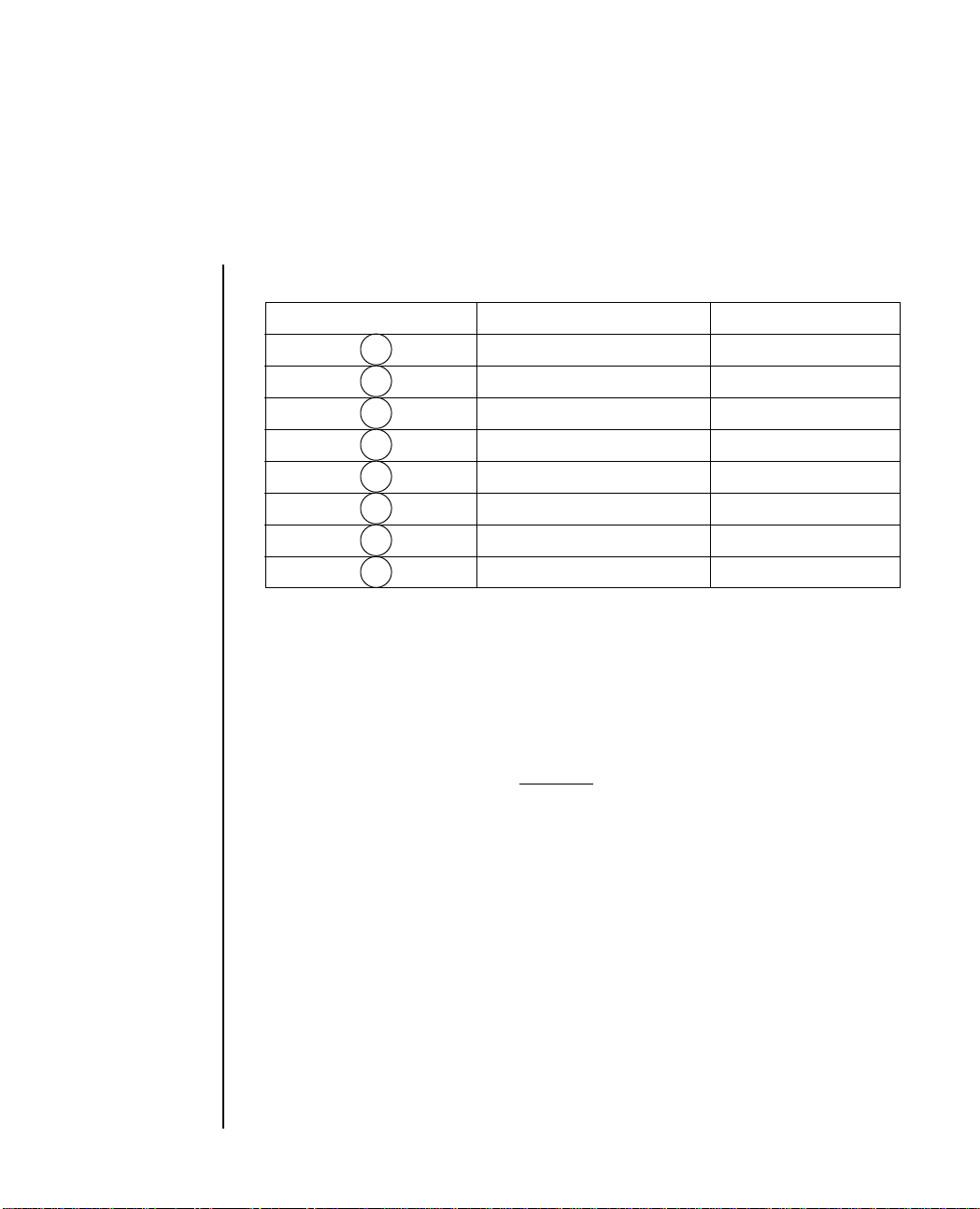
Column Position Values
Column Position Decimal Value Bit
128 2
64 2
32 2
16 2
82
42
22
12
Example:
64
16
8
4
1
Enter 93 as CHR$(93)
7
6
5
4
3
2
1
0
If we call the number for each column C1, etc., then the complete
statement looks like this:
LPRINT CHR$(27);CHR$(75);CHR$(144);CHR$(1);CHR$(C1);
CHR$(C2); ... ;CHR$(C400)
column data col. 1 ...col. 400
The format is the same for all density modes; the only differences are in
the start graphics code and in the maximum amount of column data that
can follow. The number representing any particular pattern of dots in a
column is the same regardless of graphics mode.
Programming 3 – 27
Page 58

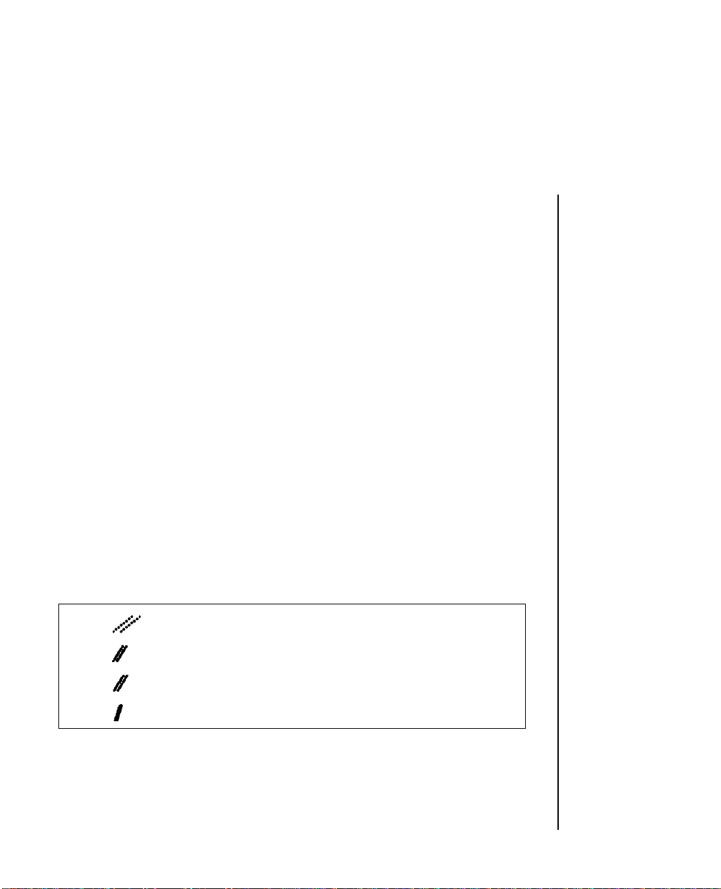
Putting it Together
Now we can work through a simple example. Suppose we want to draw
two diagonal lines. As drawn on graph paper, they look like this:
Step 1. Begin with LPRINT and the start graphics code for single
density graphics:
10 LPRINT CHR$(27);CHR$(75);
Step 2. Count the columns in the image. There are 11, so we calculate
n1 and n2:
n2 = 0
256 11
n1 = 11
and add them to the statement:
10 LPRINT CHR$(27);CHR$(75);CHR$(11);CHR$(0)
3 – 28 Programming
0
Page 59

Step 3. Next add the dot values for each column and insert them in the
statement:
10 LPRINT CHR$(27);CHR$(75);CHR$(11);CHR$(0);CHR$(1);CHR$(2)
CHR$(4);CHR$(9);CHR$(18);CHR$(36);CHR$(72);CHR$(144);
CHR$(32);CHR$(64);CHR$;(128)
Step 4. Now run the program. The result should look like this:
If it does not, check your arithmetic and typing, then try again.
Now go back and change the start graphics code to double density, half
speed (ESC L):
20 LPRINT CHR$(27);CHR$(76);CHR$(11);CHR$(0);CHR$(1),CHR$(2)
CHR$(4);CHR$(9);CHR$(18);CHR$(36);CHR$(72);CHR$(144);
CHR$(32);CHR$(64);CHR$(128)
Run the program and compare:
Programming 3 – 29
Page 60
Notice that the angle is steeper and the two lines are closer together. This
is because each individual column now overlaps the next one. Notice
also that it prints more slowly, although with this amount of printing the
difference in speed may be hard to detect.
Now try double density, normal speed (ESC Y):
30 LPRINT CHR$(27);CHR$(89);CHR$(11);CHR$(0);CHR$(1);
CHR$(2);CHR$(4);CHR$(9);CHR$(18);CHR$(36);CHR$(72);
CHR$(144);CHR$(32);CHR$(64);CHR$(128)
Aside from printing speed, there should be no difference, because the
pattern does not include adjacent dots; if it had, some dots would have
been skipped.
Finally, try quadruple density (ESC Z):
40 LPRINT CHR$(27);CHR$(90);CHR$(11);CHR$(0);CHR$(1);
CHR$(2);CHR$(4);CHR$(18);CHR$(36);CHR$(72);
CHR$(144); CHR$(32);CHR$(64);CHR$(128)
Compare the results:
The angle is even steeper, and the two lines have merged into one thick
line because of even greater overlap.
3 – 30 Programming
Page 61

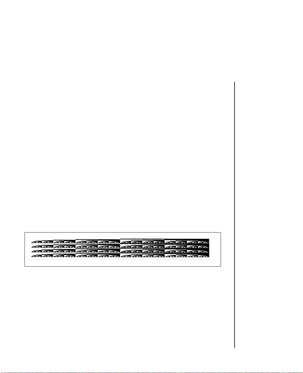
Here is another sample program that uses a FOR-NEXT loop to print all
the possible combinations of dots and spaces in numeric order:
10 REM SAMPLE 2
20 WIDTH “LPT1:”,255
30 NDOTS = 256 ‘MAXIMUM POSSIBLE COMBINATIONS
40 LPRINT CHR$(27);CHR$(75);CHR$(NDOTS MOD 256);
CHR$(FIX(NDOTS/256));
50 REM START GRAPHICS 256 COLUMNS
60 FOR I=0 TO NDOTS-1
70 LPRINT CHR$(I);
80 NEXT I
90 PRlNT:REM LINE FEED
A word of explanation about line 20. The IBM Personal Computer is set
for a maximum line length of 80 characters, so it adds a Carriage Return
and Line Feed after the 80th character. Because the data for each column
is treated as a character, your computer will send CR and LF codes after
the data for the 80th column, and the printer will interpret these codes
as graphics information and print them. A WIDTH statement changes
the maximum length of a line, and placing the number 255 in a WIDTH
statement eliminates any length restriction. (See your IBM BASIC Manual
for details.)
The printout looks like this:
Programming 3 – 31
Page 62

You can vary the length of the graphics line by changing the value of
NDOTS.
Try changing the density in this program and see what happens. Save
this program; you will need it later.
Combining Text and Graphics
You can mix normal text printing and graphics on the same
line. Here is an example using the image coded in the last
section:
05 ‘SAMPLE 3
10 LPRINT “TEXT PRINTING ”;CHR$(27);CHR$(75);
CHR$(11);CHR$(0);CHR$(1);CHR$(2);CHR$(4);CHR$(9);
CHR$(18);CHR$(36);CHR$(72);CHR$(144);CHR$(32);
CHR$(64);CHR$(128); “ TEXT PRINTING AGAIN”
Here is the result:
The printer prints normally until it receives the start graphics code. It
then prints the number of graphics columns specified by n1 and n2 and
automatically returns to normal printing.
Note: Be careful to enter the amount of graphics data you told the printer to expect;
otherwise the results will be garbled
3 – 32 Programming
Page 63

Printing Multiline Graphics
One LPRINT statement cannot print more than one line of graphics, so
you have to enter a separate LPRINT statement for each subsequent line
of graphics.
To illustrate this, add these lines to the SAMPLE 2 program:
40 FOR J = 1 TO 4
75 NEXT J
This loop causes the LPRINT statement to be repeated four times. Here
is the result:
Notice that there is a space between each pair of lines. This is because the
standard distance from the top of one line to the top of the next is 1/6
inch, but a column of graphics is only 1/9 inch high (8 dots x 1/72 inch
per dot = 8/72 inch = 1/9 inch). To print a continuous image with no gaps
between the lines, you must use the ESC A command to change line
height to 8/72 inch and ESC 2 to activate the change. Add these lines:
30 LPRINT CHR$(27);CHR$(65);CHR$(8)
35 LPRINT CHR$(27);CHR$(50)
Programming 3 – 33
Page 64
The modified program now looks like this:
10 REM SAMPLE 2
15 WIDTH “LPT1:”,255
20 NDOTS = 256
25 REM MAXIMUM POSSIBLE COMBINATIONS
30 LPRINT CHR$(27);CHR$(65);CHR$(8)
35 LPRINT CHR$(27);CHR$(50)
40 FOR J = 1 TO 4
45 LPRINT CHR$(27);CHR$(75);CHR$(NDOTS MOD 256);
CHR$(FIX (NDOTS/256));
50 REM START GRAPHICS 256 COLUMNS
55 FOR I=0 TO NDOTS-1
60 LPRINT CHR$(I);
65 NEXT I
70 LPRINT : REM LINE FEED
75 NEXT J
The result looks like this:
3 – 34 Programming
Page 65

Reminders
1. Make sure you have entered column data for the same number of
columns as specified by n1 and n2 in your LPRINT statement. If you
enter too much or too little data, the results will be garbled.
2. You can print no more than the maximum number of columns for
your graphics density mode. If more data is contained in the LPRINT
statement, the excess will simply be ignored.
3. Observe the limitations on dot placement in these graphics density
modes:
Double density, normal speed (ESC Y) and quadruple density (ESC Z)
skip at least one dot position between dots on the same horizontal row.
The printer will not print a dot placed closer than this.
Hints
The ways you can use features of BASIC to program graphics are limited
only by your imagination and your programming experience. In this
section we summarize the tricks used in the examples and suggest a few
new ones.
MOD and FIX can be very helpful in calculating the number of columns
of graphics data.
You can use the type of FOR-NEXT loop shown in sample 2 in some cases
where the dot pattern can be described by a mathematical function; a
straight line or a sine wave, for example.
Programming 3 – 35
Page 66
To simplify typing the column data, you can enter the values in a DATA
statement, then use a READ statement in a loop to print it. Here is a
model:
.
.
.
30 LPRINT CHR$(27);CHR$(75);CHR$(NDOTS MOD 256);
CHR$(FIX(NDOTS/256);
40 FOR I = 1 TO NDOTS
50 READ C
60 LPRINT CHR$(C):
70 NEXT I
.
.
.
100 DATA 2, 4, 8, 16, 32...........
This method makes it easier to check and modify your data. Using a
variable such as NDOTS helps to make sure the amount of data in the
program matches the number of columns you have specified.
Cancel Function
ASCII Decimal Hexadecimal
CAN 24 18
The cancel code clears the printer buffer. All control codes remain in
effect until you give a specific command to change them or turn the
printer off, with the exception of SO (double-width), which is cancelled.
3 – 36 Programming
Page 67

Line Feed
ASCII Decimal Hexadecimal
LF10 0A
VT 11 0B
Execution of the VT or LF command causes one line of data to be printed,
and also causes the paper to advance one line.
Paper Out
ASCII Decimal Hexadecimal
ESC 8 27 56 1B 38
ESC 9 27 57 1B 39
If you want to disable the paper out alarm (the paper indicator will not
light when paper is low) enter the ESC 8 command. If you want to be
signaled by the printer when paper is low or out, (this is the default
setting) use the ESC 8 command.
Near Letter Quality Mode
ASCII Decimal Hexadecimal
ESC I ETX 27 73 3 1B 49 03
When you want to make a good impression with a memorandum or
letter, use OKI’s special near letter quality mode. In this mode the printer
prints over each line twice. On the second pass, the printer fills in the dot
pattern to form a sharp, crisp letter. You get great results when you print
your word-processing files in this mode.
Programming 3 – 37
Page 68

Utility Mode
ASCII Decimal Hexadecimal
ESC I SOH 27 73 1 1B 49 01
The first time you turn your printer on, it will automatically print in
utility mode. In this mode, the printer prints bidirectionally. This
printing method increases the printer’s speed, so it prints 200 characters
per second.
HSD Mode
ASCII Decimal Hexadecimal
ESC # 0 27 35 48 1B 23 30
This printing method increases the printer’s speed, so it prints 240
characters per second.
3 – 38 Programming
Page 69

Appendix A
Programming Commands
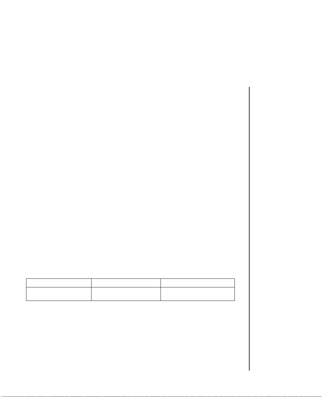
Description ASCII Decimal Hexadecimal
Carriage Return
Prints data and returns CR 13 0D
print head to the left
margin position
Character Sets
Selects Character Set One ESC 7 27 55 1B 37
Selects Character Set Two ESC 6 27 54 1B 36
Character Size
10 CPI DC2 18 12
12 CPI ESC : 27 58 1B 3A
17.1 CPI SI 15 0F
Double width SO 14 0E
Turns off double width DC4 20 14
before end of line
Turns double width ESC W 1 27 87 49 1B 57 31
on permanently
Turns double width ESC W 0 27 87 48 1B 57 30
off permanently
Clear Buffer
Resets normal width CAN 24 18
Cut Sheet Feeder
Single sheet insert ESC EM I 27 25 73 1B 19 49
Single sheet eject ESC EM R 27 25 82 1B 19 52
Emphasized/Enhanced
Printing
Doubles characters ESC G 27 71 1B 47
vertically (enhanced)
Doubles characters ESC E 27 69 1B 45
horizontally (emphasized)
Cancels emphasized ESC F 27 70 1B 46
printing
Cancels enhanced printing ESC H 27 72 1B 48
Appendix A: Programming Commands A – 1
Page 70

Description ASCII Decimal Hexadecimal
Formatting
Specifies the length of a page ESC C n 27 67 n 1B 43 n
or
ESC C NUL m 27 67 0 m 1B 43 00 m
Skip over perforation ESC N n 27 78 n 1B 4E n
advances paper when less
than 1 inch remains at
bottom of page
Cancels skip over perforation ESC O 27 79 1B 4F
Form Feed
Prints data in buffer, returns FF 12 0C
the carriage, then advances
paper to the top of the
next page
Graphics
Prints data in single-density ESC K 27 75 1B 4B
bit image graphics mode;
60 x 72 DPI
Prints data in half-speed, ESC L 27 76 1B 4C
double-density bit image
graphics mode; 120 x 72 DPI.
Prints data in normal-speed, ESC Y 27 89 1B 59
double-density bit image
graphics mode; 120 x 72 DPI.
Prints data in quadruple- ESC Z 27 90 1B 5A
density bit image graphics
mode; 240 x 72 DPI
Horizontal Tab
Tabs to next horizontal HT 9 09
tab stop
Cancel tabs ESC D NUL 27 68 0 1B 44 00
Line Feed
Advances paper one line LF 10 0A
Advances paper one line VT 11 0B
A – 2 Appendix A: Programming Commands
Page 71

Description ASCII Decimal Hexadecimal
Line Spacing
Loads variable fine line ESC A n 27 65 n 1B 41 n
spacing
Sets line spacing to variable ESC 2 27 50 1B 32
fine line spacing
Set the line feed to 7/72 inch ESC 1 27 49 1B 31
8 LPI ESC 0 27 48 1B 30
Sets the specified line space ESC 3 n 27 51 n 1B 33 n
Line spaces n/216 inch ESC J n 27 74 n 1B 4A n
Paper Out Alarm
Paper indicator lights ESC 9 27 57 1B 39
whenever paper is low or out.
Printer will not respond to ESC 8 27 56 1B 38
a paper out condition.
Printer will continue
printing even if paper is out
Print Mode
NLQ mode ESC I ETX 27 73 3 1B 49 03
UTILITY mode ESC I SOH 27 73 1 1B 49 01
HSD mode ESC # 0 27 35 48 1B 23 30
Superscript and Subscript
Selects superscripts ESC S 0 27 83 48 1B 53 30
Cancels superscript and ESC T 27 84 1B 54
subscripts
Selects subscripts ESC S 1 27 83 49 1B 53 31
Underlining
Begin underlining ESC - 1 27 45 49 1B 2D 31
Stop underlining ESC - 0 27 45 48 1B 2D 30
Appendix A: Programming Commands A – 3
Page 72

Appendix B
Character Sets
Standard Code Table (selected by ESC ! 0)
0123 6701 345
0
1
2
3
4
5
6
7
8
BS
HT
9
LF
A
B
VT
C
FF
SP SP
!
DC1
"
DC2
1
DC3
$4
DC4
%
2
'
(
CAN
)
*
ESC
+
,
45 2 67
3 4
1A
2
B
3
C
D
5
E
6
F
7
G
8
H
9
I
J
:
K
;
L
<
11
P
Q
R
S
T
U
V
W
X
Y
Z
6
7
p
a
q
b
r
c
s
d
t
e
u
f
v
g
w
h
x
BS
i
y
HT
zj
LF
12
k
l
VT
13
FF
DC1
DC2
DC3
DC4
CAN
ESC
!
"
1
$4
%
2
'
(
)
*
+
,
3 4
1A
2
B
3
C
D
5
E
6
F
7
G
8
H
9
I
J
:
K
;
L
<
11
P
Q
R
S
T
U
V
W
X
Y
Z
6
7
p
a
q
b
r
c
s
d
t
e
u
f
v
g
w
h
x
i
y
zj
12
k
13
l
D
CR
E
SO
F
SI
-
=
.
>
?
/
8
M
9
N
10
5
14
m
n
o
CR
15
SO
SI
-
=
.
>
?
/
8
M
9
N
10
5
14
m
15
n
o
Note: See Page 1-17 for Character Set Table, and description of national characters,
i.e. ➂.
Character Sets B – 1
Page 73

Block Graphics 8-Bit Code Table (selected by ESC ! 1)
0123
0
1
2
3
4
DC1
DC2
DC3
DC4
5
6
7
8
BS CAN
HT
9
LF
A
VT
B
C
ESC
FF
SP
!
"
1
$
%
2
'
(
)
*
+
,
3 4
1
2
3
4
5
6
7
8
9
:
;
<
56789ABCD
4
P
A
Q
B
R
C
S
D
T
E
U
F
V
G
W
H
X
I
Y
Z
J
6
K
7
L
p
11
a
q
b
r
c
s
d
t
e
u
f
v
g
w
h
x
i
y
j
z
12
k
13
l
EF
CR
D
SO
E
SI
F
B – 2 Character Sets
-
=
M
.
>
N
/
?
5
m
8
9
10
14
n
15
o
Page 74

Appendix C
Specifications
1. Performance
Print Speed
Utility mode (UTL) 200 cps at 10, 12, and 17.1 CPI
Near Letter Quality (NLQ) mode 50 cps at 10 and 12 CPI
High Speed Draft (HSD) 240 cps at 10 and 17.1 CPI
Super Speed Draft (SSD) 300 cps at 12 CPI
Resident fonts High Speed Draft, Utility,
Print Technique Bidirectional/short line seeking
2. Printing
Dot Matrix, standard characters 9 x 17 (NLQ)
Characters per line 80 standard size
3. Media
Courier (NLQ mode)
9 x 9 (UTL)
7 x 9 (HSD)
132 condensed size
Number of sheets Original + 3 copies
Paper feed Top with paper separator
Top with optional cut sheet feeder
Rear with pin platen feed
Bottom with optional pull tractor
Paper thickness 0.011in (0.28mm) maximum
Paper weight 14-20lb. (53-75g/m2 (fanfold)
16-21lb. (60-81g/m2 (cut sheet)
Continuous paper width 3 to 9.5in (76 to 241mm)
Ribbon Cartridge with 3 million character
life
Seamless ribbon with reinking
4. Interfaces
Parallel Centronics
Serial RS-232C
Appendix C: Specifications C – 1
Page 75

5. Reliability
Mean Time Between Failures (MTBF) 6,000 hours
Mean Time To Repair (MTTR) 15 minutes
Print head life 200 million characters
6 . Operating Conditions
Operation Temperature 5˚ to 40˚C
Humidity 20 to 80% RH without
condensation
Storage Temperature -40˚ to 70˚C
Humidity 5 to 95% RH without
condensation
7. Electrical Requirements
Voltage 230 VAC (+6%, -14%)
240 VAC ( ± 10%)
Frequency 50/60 Hz (± 2%)
8. Noise Level 58 dBA
9. Physical Specifications
Width 360 mm
Depth 275 mm
Height 80 mm
Weight 4.5 kg
10. Accessories and Consumables
Pull tractor kit Automatic cut sheet feeder
Roll paper stand 19.2kb RS–232C serial interface
9.6kb Current Loop serial interface Black fabric ribbon cartridge
C – 2 Appendix C: Specifications
Page 76
Hexadecimal Conversion Table
0123 6789 BCD
0
0
16
32 64
1
17
18
19
20
21
22
23
24
25
26
27
28
33
34
35
36
37
38
39
40
41
42
43
44
1
2
2
3
3
4
4
5
5
6
6
7
7
8
8
9
9
10
A
11
B
12
C
45 A EF
48
49
50
51
52
53
54
55
56
57
58
59
60
65
66
67
68
69
70
71
72
73
74
75
76
80
81
82
83
84
85
86
87
88
89
90
91
92
96
97
98
99
100
101
102
103
104
105
106
107
108
112
113
114
115
116
117
118
119
120
121
122
123
124
128
129
130
131
132
133
134
135
136
137
138
139
140
144
145
146
147
148
149
150
151
152
153
154
155
156
160
161
162
163
164
165
166
167
168
169
170
171
172
176
177
178
179
180
181
182
183
184
185
186
187
188
192
193
194
195
196
197
198
199
200
201
202
203
204
208
209
210
211
212
213
214
215
216
217
218
219
220
224
225
226
227
228
229
230
231
232
233
234
235
236
240
241
242
243
244
245
246
247
248
249
250
251
252
D
13
29
E
14
30
F
15
31
45
46
47
61
62
63
77
78
79
93
94
95
109
110
111
125
126
127
141
142
143
157
158
159
173
174
175
189
190
191
205
206
207
Note: Hexadecimal values are represented in the first row and column.
For a hexadecimal value of 9A, look along the top row for the first digit (9). Look
down the left-hand column for the second digit (A). The decimal equivalent value
will be found where column 9 and row A intersect.
Therefore: 9A (hex.) = 154 (decimal).
Character Sets B – 3
221
222
223
237
238
239
253
254
255
 Loading...