

Page 1
ML1100
Technical Reference Guide
ML1120/ML1190
Page 2

P
REFACE
Every effort has been made to ensure that the information in this document is
complete, accurate, and up-to-date. Oki Printing Solutions assumes no
responsibility for the results of errors beyond its control. Oki Printing Solutions also
cannot guarantee that changes in software and equipment made by other
manufacturers and referred to in this guide will not affect the applicability of the
information in it. Mention of software products manufactured by other companies
does not necessarily constitute endorsement by Oki Printing Solutions.
While all reasonable efforts have been made to make this document as accurate and
helpful as possible, we make no warranty of any kind, expressed or implied, as to
the accuracy or completeness of the information contained herein.
The most up-to-date drivers and manuals are available from the Oki Printing
Solutions web site:
http://www.okiprintingsolutions.com
Copyright © 2006 Oki Printing Solutions.
Oki, OKI Printing Solutions and Microline are registered trademarks of Oki Electric
Industry Company, Ltd.
ENERGY STAR is a trademark of the United States Environmental Protection Agency.
Microsoft, MS-DOS and Windows are registered trademarks of Microsoft
Corporation.
Other product names and brand names are registered trademarks or trademarks of
their proprietors.
As an ENERGY STAR Program Participant, the manufacturer has
determined that this product meets the ENERGY STAR guidelines
for energy efficiency.
This product complies with the requirements of the Council
Directives 89/336/EEC (EMC) and 73/23/EEC (LVD) as amended
where applicable on the approximation of the laws of the member
states relating to electromagnetic compatibility and low voltage.
Technical Reference Guide – Preface > 2
Page 3

C
ONTENTS
Preface . . . . . . . . . . . . . . . . . . . . . . . . . . . . . . . . . . . . 2
Notes, cautions and warnings. . . . . . . . . . . . . . . . . . 10
Introduction . . . . . . . . . . . . . . . . . . . . . . . . . . . . . . . 11
Features . . . . . . . . . . . . . . . . . . . . . . . . . . . . . . . . 11
Standard configuration . . . . . . . . . . . . . . . . . . . . . . 12
Identifying component parts . . . . . . . . . . . . . . . . . . 13
Front view . . . . . . . . . . . . . . . . . . . . . . . . . . . . . 13
Rear view . . . . . . . . . . . . . . . . . . . . . . . . . . . . . 14
About this guide . . . . . . . . . . . . . . . . . . . . . . . . . . . . 16
Online usage . . . . . . . . . . . . . . . . . . . . . . . . . . . . . 17
Printing pages . . . . . . . . . . . . . . . . . . . . . . . . . . . . 17
Interface specifications . . . . . . . . . . . . . . . . . . . . . . 19
IEEE1284 parallel interface specifications . . . . . . . . . 19
Connectors and cable . . . . . . . . . . . . . . . . . . . . . 19
Parallel interface signals . . . . . . . . . . . . . . . . . . . 20
Parallel interface levels . . . . . . . . . . . . . . . . . . . . 20
Parallel interface circuits . . . . . . . . . . . . . . . . . . . 21
Parallel interface timing chart . . . . . . . . . . . . . . . 21
Support mode . . . . . . . . . . . . . . . . . . . . . . . . . . 21
Universal Serial Bus (USB). . . . . . . . . . . . . . . . . . . . 21
Connectors . . . . . . . . . . . . . . . . . . . . . . . . . . . . 22
Cable . . . . . . . . . . . . . . . . . . . . . . . . . . . . . . . . 22
USB interface signals . . . . . . . . . . . . . . . . . . . . . 22
Mode and class of device. . . . . . . . . . . . . . . . . . . 23
Data signalling rate . . . . . . . . . . . . . . . . . . . . . . 23
Interface circuit . . . . . . . . . . . . . . . . . . . . . . . . . 24
Signal level . . . . . . . . . . . . . . . . . . . . . . . . . . . . 24
Timing chart . . . . . . . . . . . . . . . . . . . . . . . . . . . 26
RS-232C serial interface specifications . . . . . . . . . . . 28
Interface signals . . . . . . . . . . . . . . . . . . . . . . . . 28
Electrical characteristics . . . . . . . . . . . . . . . . . . . 29
Interface timing charts . . . . . . . . . . . . . . . . . . . . 30
Receiving margin . . . . . . . . . . . . . . . . . . . . . . . . 30
Description of communication procedures . . . . . . . 30
Interface control code. . . . . . . . . . . . . . . . . . . . . 30
Local test function . . . . . . . . . . . . . . . . . . . . . . . 32
Operator interface. . . . . . . . . . . . . . . . . . . . . . . . . . . 34
Operator panel functions . . . . . . . . . . . . . . . . . . . . . 34
Print mode . . . . . . . . . . . . . . . . . . . . . . . . . . . . 35
Hex Dump mode, Menu mode, Test mode. . . . . . . 37
Technical Reference Guide – Preface > 3
Page 4

Maintenance mode 1 . . . . . . . . . . . . . . . . . . . . . 38
Maintenance mode 2 . . . . . . . . . . . . . . . . . . . . . 38
Lamp functions. . . . . . . . . . . . . . . . . . . . . . . . . . . . 39
ML1120. . . . . . . . . . . . . . . . . . . . . . . . . . . . . . . 39
ML1190. . . . . . . . . . . . . . . . . . . . . . . . . . . . . . . 40
Alarm/error indications . . . . . . . . . . . . . . . . . . . . . . 40
Recoverable alarms . . . . . . . . . . . . . . . . . . . . . . 40
Unrecoverable alarms . . . . . . . . . . . . . . . . . . . . . 41
Menu selection . . . . . . . . . . . . . . . . . . . . . . . . . . . . 43
Overview. . . . . . . . . . . . . . . . . . . . . . . . . . . . . . 43
Button switch functions. . . . . . . . . . . . . . . . . . . . 44
Operation . . . . . . . . . . . . . . . . . . . . . . . . . . . . . 44
Menu items . . . . . . . . . . . . . . . . . . . . . . . . . . . . 45
Initialising menu settings . . . . . . . . . . . . . . . . . . 53
Initialising menu settings . . . . . . . . . . . . . . . . . . 54
Adjusting TOF position . . . . . . . . . . . . . . . . . . . . . . 55
Printer speed settings . . . . . . . . . . . . . . . . . . . . . . . 56
Printer impact mode . . . . . . . . . . . . . . . . . . . . . . 56
Registration menu . . . . . . . . . . . . . . . . . . . . . . . . . 57
Overview. . . . . . . . . . . . . . . . . . . . . . . . . . . . . . 57
Operation . . . . . . . . . . . . . . . . . . . . . . . . . . . . . 57
Registration details. . . . . . . . . . . . . . . . . . . . . . . 57
Self test printing. . . . . . . . . . . . . . . . . . . . . . . . . . . 57
Rolling ASCII self test printing . . . . . . . . . . . . . . . . . 58
Hexadecimal Dump mode . . . . . . . . . . . . . . . . . . . . 59
Overview. . . . . . . . . . . . . . . . . . . . . . . . . . . . . . 59
Operation . . . . . . . . . . . . . . . . . . . . . . . . . . . . . 60
Function . . . . . . . . . . . . . . . . . . . . . . . . . . . . . . 60
Continuous paper auto-loading. . . . . . . . . . . . . . . . . 60
Continuous paper auto-parking . . . . . . . . . . . . . . . . 61
Cut-sheet paper semi-auto-loading . . . . . . . . . . . . . . 61
Form tear-off . . . . . . . . . . . . . . . . . . . . . . . . . . . . . 62
Function . . . . . . . . . . . . . . . . . . . . . . . . . . . . . . 62
Set-up . . . . . . . . . . . . . . . . . . . . . . . . . . . . . . . 62
Action . . . . . . . . . . . . . . . . . . . . . . . . . . . . . . . . 62
Command descriptions . . . . . . . . . . . . . . . . . . . . . . . 63
Horizontal control . . . . . . . . . . . . . . . . . . . . . . . . . . 63
Carriage return . . . . . . . . . . . . . . . . . . . . . . . . . 63
Horizontal tab set. . . . . . . . . . . . . . . . . . . . . . . . 63
Horizontal tab . . . . . . . . . . . . . . . . . . . . . . . . . . 65
Reset tab settings to power-on default values . . . . 65
Execute absolute horizontal dot position . . . . . . . . 66
Execute relative dot position . . . . . . . . . . . . . . . . 66
Technical Reference Guide – Preface > 4
Page 5

Move right relative dot position . . . . . . . . . . . . . . 68
Move left relative dot position . . . . . . . . . . . . . . . 69
Left margin set . . . . . . . . . . . . . . . . . . . . . . . . . 69
Right margin set . . . . . . . . . . . . . . . . . . . . . . . . 70
Set left/right margin. . . . . . . . . . . . . . . . . . . . . . 71
Auto justification . . . . . . . . . . . . . . . . . . . . . . . . 72
Set/reset unidirection printing . . . . . . . . . . . . . . . 73
One line unidirectional printing . . . . . . . . . . . . . . 74
Set/reset half speed printing . . . . . . . . . . . . . . . . 74
Backspace . . . . . . . . . . . . . . . . . . . . . . . . . . . . . 75
One character data delete . . . . . . . . . . . . . . . . . . 76
Vertical control. . . . . . . . . . . . . . . . . . . . . . . . . . . . 76
Set 1/8 inch fixed line spacing . . . . . . . . . . . . . . . 76
Set 7/72 inch fixed line spacing . . . . . . . . . . . . . . 77
Start line spacing . . . . . . . . . . . . . . . . . . . . . . . . 77
Set 1/6 inch line spacing. . . . . . . . . . . . . . . . . . . 77
Set n/60 inch line spacing . . . . . . . . . . . . . . . . . . 78
Set n/180 inch line spacing . . . . . . . . . . . . . . . . . 78
Set n/360 inch fine line spacing . . . . . . . . . . . . . . 79
Set n/360 inch line spacing . . . . . . . . . . . . . . . . . 80
Line feed. . . . . . . . . . . . . . . . . . . . . . . . . . . . . . 80
Set/reset automatic linefeed . . . . . . . . . . . . . . . . 81
Fine line feed (n/180 inch) . . . . . . . . . . . . . . . . . 81
Fine line feed (n/360 inch) . . . . . . . . . . . . . . . . . 82
Fine line feed (n/360 inch) . . . . . . . . . . . . . . . . . 83
Reverse line feed . . . . . . . . . . . . . . . . . . . . . . . . 83
Reverse line feed . . . . . . . . . . . . . . . . . . . . . . . . 84
Form feed . . . . . . . . . . . . . . . . . . . . . . . . . . . . . 84
Vertical tab . . . . . . . . . . . . . . . . . . . . . . . . . . . . 85
Set vertical tab stops . . . . . . . . . . . . . . . . . . . . . 86
Set vertical format unit (VFU) . . . . . . . . . . . . . . . 86
Select vertical tab channel . . . . . . . . . . . . . . . . . 87
Form length set by inches . . . . . . . . . . . . . . . . . . 88
Form length set by lines . . . . . . . . . . . . . . . . . . . 88
Set perforation auto skip. . . . . . . . . . . . . . . . . . . 89
Reset perforation auto skip . . . . . . . . . . . . . . . . . 90
Top of form set . . . . . . . . . . . . . . . . . . . . . . . . . 90
Set vertical units . . . . . . . . . . . . . . . . . . . . . . . . 91
Set n/360 inch fine line spacing . . . . . . . . . . . . . . 91
Set n/360 inch line spacing . . . . . . . . . . . . . . . . . 92
Set forward line spacing . . . . . . . . . . . . . . . . . . . 92
Set reverse line spacing . . . . . . . . . . . . . . . . . . . 92
Character set . . . . . . . . . . . . . . . . . . . . . . . . . . . . . 92
Technical Reference Guide – Preface > 5
Page 6

Copies ROM CG to RAM CG . . . . . . . . . . . . . . . . . 92
Character definition . . . . . . . . . . . . . . . . . . . . . . 93
Load DLL character. . . . . . . . . . . . . . . . . . . . . . . 95
DLL font select. . . . . . . . . . . . . . . . . . . . . . . . . . 97
Foreign character set select. . . . . . . . . . . . . . . . . 97
Select international character set . . . . . . . . . . . . .100
Select character table . . . . . . . . . . . . . . . . . . . . .101
Enable upper ASCII characters . . . . . . . . . . . . . .101
Select character set II . . . . . . . . . . . . . . . . . . . .101
Print continuously from all characters chart . . . . . .102
Print one character from all characters chart . . . . .102
Select character set I . . . . . . . . . . . . . . . . . . . . .103
Select character set II . . . . . . . . . . . . . . . . . . . .103
Code page select . . . . . . . . . . . . . . . . . . . . . . . .103
Assign character table . . . . . . . . . . . . . . . . . . . .106
Select character table . . . . . . . . . . . . . . . . . . . . .107
Select font. . . . . . . . . . . . . . . . . . . . . . . . . . . . .108
Print quality – select HSD . . . . . . . . . . . . . . . . . .108
Print quality – select HSD . . . . . . . . . . . . . . . . . .109
Font description . . . . . . . . . . . . . . . . . . . . . . . . . . .109
Select character font . . . . . . . . . . . . . . . . . . . . .109
Select type styles. . . . . . . . . . . . . . . . . . . . . . . .110
Set/reset proportional spacing . . . . . . . . . . . . . . .111
Set/reset proportional spacing . . . . . . . . . . . . . . .112
Set pica character pitch (10 CPI) . . . . . . . . . . . . .113
Set 10 CPI. . . . . . . . . . . . . . . . . . . . . . . . . . . . .113
Set elite character pitch (12 CPI) . . . . . . . . . . . . .113
Set 12 CPI. . . . . . . . . . . . . . . . . . . . . . . . . . . . .114
Set 15 character per inch . . . . . . . . . . . . . . . . . .114
Set compressed character pitch (17.1/20 CPI). . . .115
Set compressed character pitch (17.1/20 CPI). . . .115
Reset compressed character pitch . . . . . . . . . . . .116
Set character spacing . . . . . . . . . . . . . . . . . . . . .116
Set italic characters . . . . . . . . . . . . . . . . . . . . . .117
Reset italic characters. . . . . . . . . . . . . . . . . . . . .117
Set italic character . . . . . . . . . . . . . . . . . . . . . . .118
Reset italic characters. . . . . . . . . . . . . . . . . . . . .118
Text print features . . . . . . . . . . . . . . . . . . . . . . . . .118
Set/reset underlining . . . . . . . . . . . . . . . . . . . . .118
Set subscript/superscript. . . . . . . . . . . . . . . . . . .119
Reset super/subscript . . . . . . . . . . . . . . . . . . . . .120
Set emphasised print mode . . . . . . . . . . . . . . . . .120
Reset emphasised print mode . . . . . . . . . . . . . . .120
Technical Reference Guide – Preface > 6
Page 7

Set double strike print mode . . . . . . . . . . . . . . . .121
Reset double strike mode . . . . . . . . . . . . . . . . . .121
Set double or expanded characters . . . . . . . . . . .122
Set immediate double width characters. . . . . . . . .122
Set immediate double width characters. . . . . . . . .123
Reset immediate double width characters . . . . . . .123
Set/reset double height characters. . . . . . . . . . . .124
Set/reset double height characters. . . . . . . . . . . .124
Set/reset double height characters. . . . . . . . . . . .125
Overscore set/reset . . . . . . . . . . . . . . . . . . . . . .126
Select character style . . . . . . . . . . . . . . . . . . . . .126
Set double width or expanded characters . . . . . . .127
Set/reset double height characters. . . . . . . . . . . .127
Graphics mode . . . . . . . . . . . . . . . . . . . . . . . . . . . .128
Enter/exit bit image graphics. . . . . . . . . . . . . . . .128
Single density graphics . . . . . . . . . . . . . . . . . . . .131
Double density graphics . . . . . . . . . . . . . . . . . . .131
Quasi-double-density graphics . . . . . . . . . . . . . . .132
Set quadruple density graphics . . . . . . . . . . . . . .133
Reassign alternate graphics codes . . . . . . . . . . . .134
Graphics resolution. . . . . . . . . . . . . . . . . . . . . . .135
Select aspect ratio . . . . . . . . . . . . . . . . . . . . . . .136
Composite commands . . . . . . . . . . . . . . . . . . . . . . .137
Print mode select . . . . . . . . . . . . . . . . . . . . . . . .137
Print mode select . . . . . . . . . . . . . . . . . . . . . . . .138
General control. . . . . . . . . . . . . . . . . . . . . . . . . . . .138
Printer initialisation . . . . . . . . . . . . . . . . . . . . . .138
Cancel code. . . . . . . . . . . . . . . . . . . . . . . . . . . .139
Set bit 7 code to 1 . . . . . . . . . . . . . . . . . . . . . . .139
Set bit 7 code to 0 . . . . . . . . . . . . . . . . . . . . . . .139
Reset 8 bit mode . . . . . . . . . . . . . . . . . . . . . . . .140
Set print suppress . . . . . . . . . . . . . . . . . . . . . . .140
Print suppress . . . . . . . . . . . . . . . . . . . . . . . . . .140
Reset print suppress mode . . . . . . . . . . . . . . . . .141
Stop printing . . . . . . . . . . . . . . . . . . . . . . . . . . .141
Enable paper out sensor . . . . . . . . . . . . . . . . . . .141
Disable paper out sensor. . . . . . . . . . . . . . . . . . .142
Select emulation . . . . . . . . . . . . . . . . . . . . . . . .143
Printer initialisation . . . . . . . . . . . . . . . . . . . . . .143
Printer initialisation . . . . . . . . . . . . . . . . . . . . . .143
Barcode. . . . . . . . . . . . . . . . . . . . . . . . . . . . . . . . .144
Print barcode . . . . . . . . . . . . . . . . . . . . . . . . . . .144
Specifications . . . . . . . . . . . . . . . . . . . . . . . . . . . . . 148
Technical Reference Guide – Preface > 7
Page 8

ML1120 . . . . . . . . . . . . . . . . . . . . . . . . . . . . . . . . .148
Physical specification . . . . . . . . . . . . . . . . . . . . .148
Power requirements . . . . . . . . . . . . . . . . . . . . . .149
Electrical insulation. . . . . . . . . . . . . . . . . . . . . . .149
Environmental conditions . . . . . . . . . . . . . . . . . .149
Noise . . . . . . . . . . . . . . . . . . . . . . . . . . . . . . . .150
Agency approvals. . . . . . . . . . . . . . . . . . . . . . . .150
Print specification. . . . . . . . . . . . . . . . . . . . . . . .151
Paper specification . . . . . . . . . . . . . . . . . . . . . . .153
Ribbon specification . . . . . . . . . . . . . . . . . . . . . .154
Reliability . . . . . . . . . . . . . . . . . . . . . . . . . . . . .154
ML1190 . . . . . . . . . . . . . . . . . . . . . . . . . . . . . . . . .155
Physical specification . . . . . . . . . . . . . . . . . . . . .155
Power requirements . . . . . . . . . . . . . . . . . . . . . .156
Electrical insulation. . . . . . . . . . . . . . . . . . . . . . .156
Environmental conditions . . . . . . . . . . . . . . . . . .156
Noise . . . . . . . . . . . . . . . . . . . . . . . . . . . . . . . .157
Agency approvals. . . . . . . . . . . . . . . . . . . . . . . .157
Print specification. . . . . . . . . . . . . . . . . . . . . . . .157
Paper specification . . . . . . . . . . . . . . . . . . . . . . .160
Ribbon specification . . . . . . . . . . . . . . . . . . . . . .161
Reliability . . . . . . . . . . . . . . . . . . . . . . . . . . . . .161
Appendix A – Command summary . . . . . . . . . . . . . 163
Command summary by initiator . . . . . . . . . . . . . . . .163
Command summary by function . . . . . . . . . . . . . . . .171
Appendix B – Print modes/features . . . . . . . . . . . . 178
IBM mode . . . . . . . . . . . . . . . . . . . . . . . . . . . . . . .178
EPSON mode . . . . . . . . . . . . . . . . . . . . . . . . . . . . .179
Appendix C – Code pages . . . . . . . . . . . . . . . . . . . . 180
Appendix D – Media specifications . . . . . . . . . . . . . 188
General . . . . . . . . . . . . . . . . . . . . . . . . . . . . . . . . .188
Unsuitable paper . . . . . . . . . . . . . . . . . . . . . . . .188
Pre-printed paper. . . . . . . . . . . . . . . . . . . . . . . .189
Paper storage conditions . . . . . . . . . . . . . . . . . . .190
Usable paper types and assurance range . . . . . . .190
Continuous paper (continuous forms) . . . . . . . . . . . .191
Vertical and horizontal dimensions . . . . . . . . . . . .191
Feed hole (sprocket hole) positions and sizes . . . .192
Perforation dimensions . . . . . . . . . . . . . . . . . . . .194
Paper size and printing areas. . . . . . . . . . . . . . . .196
Paper quality . . . . . . . . . . . . . . . . . . . . . . . . . . .197
Paper weight and max. no. of form parts . . . . . . .198
Technical Reference Guide – Preface > 8
Page 9

Methods for joining parts of multipart forms . . . . .198
Horizontal perforation rising . . . . . . . . . . . . . . . .202
Misalignment between feed holes. . . . . . . . . . . . .203
Binding holes. . . . . . . . . . . . . . . . . . . . . . . . . . .203
Corner cuts . . . . . . . . . . . . . . . . . . . . . . . . . . . .204
Paper condition . . . . . . . . . . . . . . . . . . . . . . . . .205
Cut-sheet paper . . . . . . . . . . . . . . . . . . . . . . . . . . .206
Vertical and horizontal dimensions . . . . . . . . . . . .206
Paper size and printing areas. . . . . . . . . . . . . . . .207
Paper quality . . . . . . . . . . . . . . . . . . . . . . . . . . .209
Paper weight and max. no. of form parts . . . . . . .209
Joining of parts of multipart forms . . . . . . . . . . . .210
Binding holes. . . . . . . . . . . . . . . . . . . . . . . . . . .211
Perforations. . . . . . . . . . . . . . . . . . . . . . . . . . . .211
Folds, bends and curls of cut-sheet paper . . . . . . .212
Envelopes (individual) . . . . . . . . . . . . . . . . . . . . . . .213
Label paper . . . . . . . . . . . . . . . . . . . . . . . . . . . . . .214
Package delivery slips . . . . . . . . . . . . . . . . . . . . . . .218
Recycled paper. . . . . . . . . . . . . . . . . . . . . . . . . . . .219
Index. . . . . . . . . . . . . . . . . . . . . . . . . . . . . . . . . . . . 220
Oki Printing Solutions contact details. . . . . . . . . . . 221
Technical Reference Guide – Preface > 9
Page 10

N
OTES, CAUTIONS AND WARNINGS
NOTE
A NOTE PROVIDES ADDITIONAL INFORMATION TO
SUPPLEMENT THE MAIN TEXT.
.
CAUTION!
A caution provides additional information which, if
ignored, may result in equipment malfunction or
damage.
WARNING!
A warning provides additional information which, if
ignored, may result in a risk of personal injury.
Technical Reference Guide – Notes, cautions and warnings. > 10
Page 11

I
NTRODUCTION
The ML1120 (9-pin) and ML1190 (24-pin) are designed to
provide highly reliable letter quality printing and high resolution
graphics for the desktop/office printing environment. Both
models combine state-of-the-art serial impact dot matrix printing
technology with advanced materials and superior construction to
provide high performance and versatility in a desktop sized unit.
Careful attention to ergonomics and application needs provides
user friendly operation for operators of varying technical
capabilities.
F
EATURES
ML1120 and ML1190 features include:
> OKI smart Paper Handling (ML1190)
> Direct access control panel
> Structured direct access menu for easy set up
> Printhead life: 200M characters (average) in 10 CPI Utility
mode at normal 25% duty, 35% page density
> Bidirectional short-line-seeking printing
> Print speed:
333 CPS HSD (10 CPI)
250 CPS Utility (10 CPI)
83 CPS NLQ (10 CPI) (ML1190)
62.5 CPS LQ (10 CPI)(ML1120)
> Paper feed
Rear path (with push tractor)
Top tray
Bottom path (with pull tractor)
> Paper handling
Automatic sheet loading
Short paper tear-off available by menu selection or TEAR
switch operation
Auto-loading for single sheet and continuous paper
Auto park feature
> Paper copies
Technical Reference Guide – Introduction > 11
Page 12

9 – 11 lb, 4 part (with rear feed)
9 – 11 lb, 6 part (with bottom feed)
> Cartridge ribbon
> Interfaces
Standard IEEE1284 parallel interface
USB interface
RS-232C Serial interface
> 53 dBA noise
> ML1190: 64 kbytes max. receive buffer
ML1120: 128 kbytes max. receive buffer
> Line feed resolution at:
ML1190: 1/6 in, 1/8 in, n/72 in,
n/144 in, n/180, n/216 in simulated by n/288 in, n360 in
ML1190: 1/6 in, 1/8 in, n/72 in,
n/144 in, n/216 in simulated by n/288 in
> Agency approved by:
200 V system: UL
230 V model: CE, GS
> Barcode data printing
> Postnet bar code data printing
S
TANDARD CONFIGURATION
The ML1120 and ML1190 consist of the following components:
> Printer mechanism
> Power supply unit
> Control board (including an IEEE1284 parallel interface,
RS-232C serial interface and USB interface)
> Operation panel board
> Acoustic covers
> Tractor feed unit
Technical Reference Guide – Introduction > 12
Page 13

NOTE
It is not recommended that you use either the parallel or USB
port when the RS-232C option is installed in this product.
I
DENTIFYING COMPONENT PARTS
The main parts of your printer are identified and briefly explained
below.
F
RONT VIEW
1
7
2
6
3
5
4
1. Print Head: prints the characters on the paper.
2. Paper Type Lever: set according to the type of paper used
– cut sheet or continuous forms.
3. Platen Knob: turn to move or eject the paper.
4. Paper Thickness Lever: set according to the thickness of
the paper. There is also a setting to facilitate ribbon
replacement.
5. Control Panel: contains button switches and indicators
(described in detail later) that allow you to operate the
printer.
Technical Reference Guide – Introduction > 13
Page 14

ML1120
PITCH
SPEED
SEL ALARM
SEL
FONT
LF/FF LOAD/EJECT TEAR
ML1190
PITCH
SPEED
SEL ALARM
SEL
FONT
LF/FF LOAD/EJECT TEAR
6. Power Switch: to turn the printer power ON/OFF.
7. Ribbon Cartridge: holds the printer ribbon.
R
EAR VIEW
4
1
STATUS
STATUS
3
2
1. Paper Tray: insert cut sheet paper for use by the printer
(one sheet at a time)
2. Power connector: connect to printer power cable.
3. Paper Guides: can be adjusted as required to locate the
left edge of cut sheet paper.
Technical Reference Guide – Introduction > 14
Page 15

4. Pin Tractor: to load and feed continuous forms.
5
7
6
5. Serial connector: connect to serial interface cable.
6. USB connector: connect to USB interface cable.
7. Parallel connector: connect to parallel interface connector.
Technical Reference Guide – Introduction > 15
Page 16

A
BOUT THIS GUIDE
NOTE
Images used in this manual may include optional features
that your printer does not have installed.
If required, you may wish to refer for basic information to the
User’s Guide which is stored on the manuals CD.
This manual is your Technical Reference guide (check the web
site, www.okiprintingsolutions.com, for the most up-to-date
version) for your printer and forms part of the overall user
support listed below:
> Installation Safety booklet: provides information as to
safe use of the printer.
This is a paper document that is packaged with the printer
and should be read before setting up your printer.
> Set-up guide: to describe how to unpack and set up your
printer.
This is a paper document that is packaged with the printer.
> This Technical Reference Guide: to provide detailed
technical information for programmers and more technical
users.
This is an electronic document available on the web site
www.okieng.com.
> User’s Guide: to help you to become familiar with your
printer and make the best use of its many features. Also
included are guidelines for troubleshooting and
maintenance to ensure that it performs at its best.
Additionally, information is provided for adding optional
accessories as your printing needs evolve.
This is an electronic document stored on the manuals CD.
> Network Configuration Guide: to provide detailed
technical information for network administrators to
configure the optional accessory network interface.
This is an electronic document stored on the CD that
accompanies the network interface card optional
accessory.
Technical Reference Guide – About this guide > 16
Page 17

> Installation Guides: accompany consumable items and
to describe how to install them.
These are paper documents that are packaged with the
consumables and optional accessories.
> Online Help: online information accessible from the
printer driver and utility software.
O
NLINE USAGE
This guide is intended to be read on screen using an Adobe
Acrobat Reader. Use the navigation and viewing tools provided in
Acrobat.
You can access specific information in two ways:
> In the list of bookmarks down the left hand side of your
screen, click on the topic of interest to jump to the
required topic. (If the bookmarks are not available, use
the “Contents” on page 3.)
> In the list of bookmarks, click on Index to jump to the
Index. (If the bookmarks are not available, use the
“Contents” on page 3.) Find the term of interest in the
alphabetically arranged index and click on the associated
page number to jump to the page containing the term.
P
RINTING PAGES
The whole manual, individual pages, or sections may be printed.
The procedure is:
1. From the toolbar, select File -> Print (or press the
Ctrl + P keys).
Technical Reference Guide – About this guide > 17
Page 18

2. Choose which pages you wish to print:
(a) [All pages], (1), for the entire manual.
(b) [Current page], (2), for the page at which you are
looking.
1
2
3
(c) [Pages from] and [to], (3), for the range of pages
you specify by entering their page numbers.
3. Click on OK.
Technical Reference Guide – About this guide > 18
Page 19

I
NTERFACE SPECIFICATIONS
IEEE1284
C
ONNECTORS AND CABLE
Connectors
Cable
PARALLEL INTERFACE SPECIFICATIONS
Printer side:
36-pin receptacle 57-40360-830B (Amphenol or Daiichi
Electronics) or equivalent
Cable side:
36-pin plug 57-30360 (Amphenol or Daiichi Electronics) or
equivalent.
Use a cable less than 6 ft (1.8 m) in total length.
(A shielded cable is required and use of twisted-pair wires
is recommended for noise prevention.)
The cable is not supplied with the printer.
Technical Reference Guide – Interface specifications > 19
Page 20

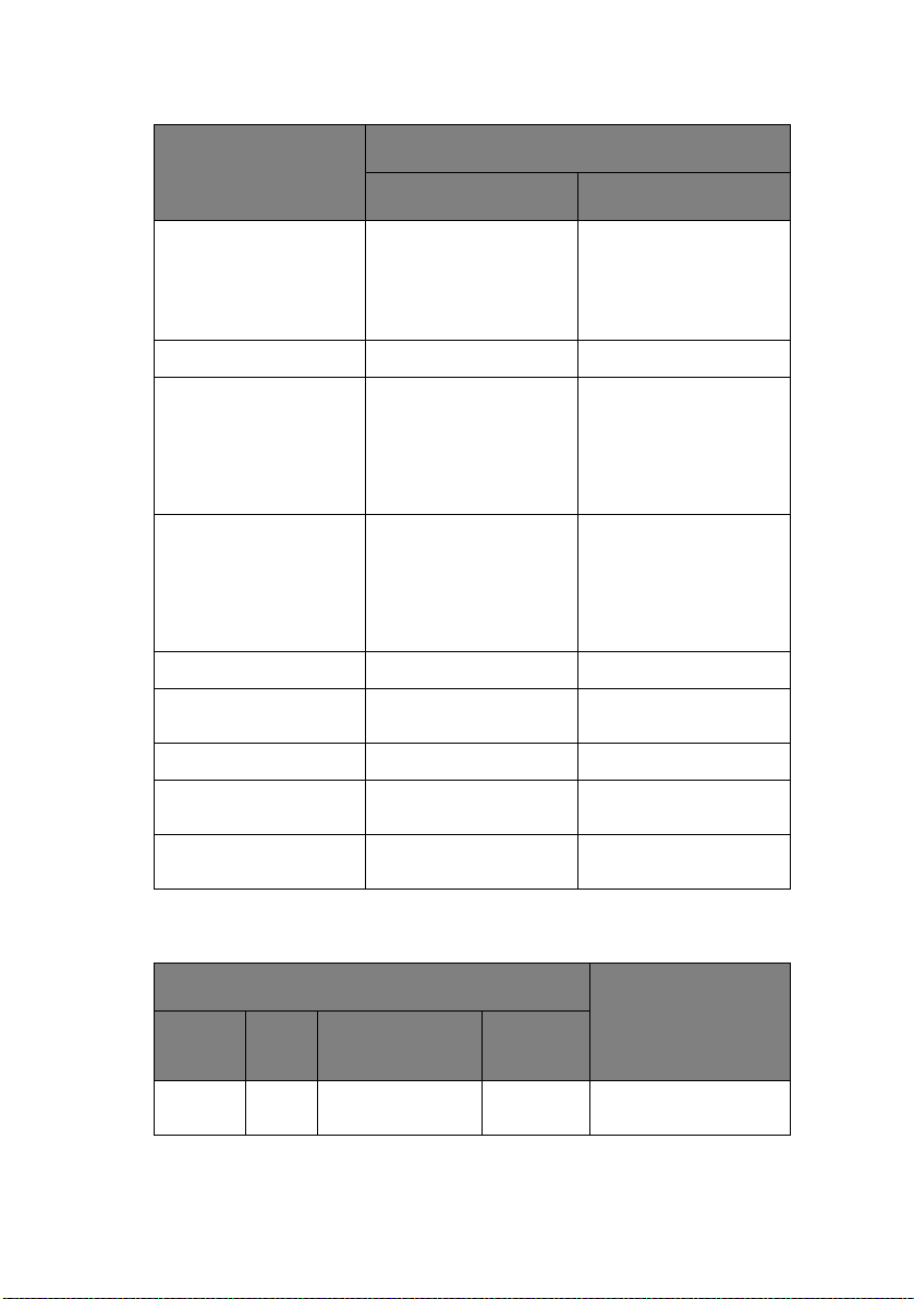
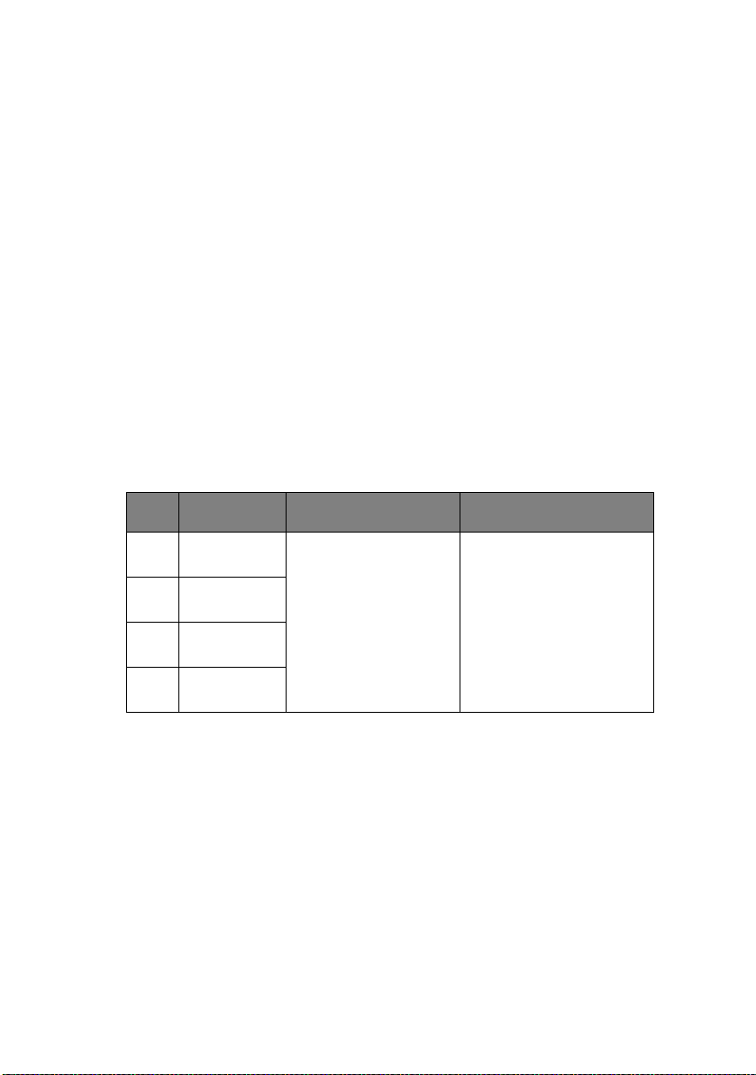
P
ARALLEL INTERFACE SIGNALS
PinNo. Direction
1
2
3
4
5
6
7
8
9
10
11
12
13
14
16, 33
17
18
19 to 30
31
32
15, 34
35
36
Signal
STROBE
DATA BIT 1
DATA BIT 2
DATA BIT 3
DATA BIT 4
DATA BIT 5
DATA BIT 6
DATA BIT 7
DATA BIT 8
ACKNLG
BUSY
PE
SEL
AUTO FEED
GND
CHASSIS GROUND
GND
INIT
ERROR
SLCT IN
To printer
To printer
From printer
From printer
From printer
From printer
To printer
To printer
From printer
To printer
NOTE
Description
Samples input data when changing from low
level to high level.
Input data: High level indicates 1 and low
level 0 .
Indicates character input completion, or function
operation end, at low level.
Indicates data cannot be received at high level.
Data can be input at low level.
High level indicates paper end.
High level indicates select (on line) condition.
“Auto Feed” in menu set as valid in EPS mode
Signal ground.
Frame ground.
Fixed to High (Connected to + 5 V via 235 K)Ω
Twisted pair return (for pin No. 1 to 11)
This signal goes from high to low level when
paper runs out.
(Possible to indicate error and Off Line state).
Unused
Fixed to High (Connected to +5 V via 3.3 K Ω)
Connected to input port
Compatible Nibble
HostClk
PrtClk
PrtBusy
AckDataReq
Xflag
HostBusy
nDataAvail
IEEE1284
active
Connector pin arrangement for above.
18
36
P
ARALLEL INTERFACE LEVELS
Low level: 0.0 V to + 0.8 V
High level: +2.4 V to +5.0 V
Technical Reference Guide – Interface specifications > 20
1
19
Page 21

P
A
ARALLEL INTERFACE CIRCUITS
(a) Receiver
(b) Driver
1
LVC161284
BUSY, ACKNOWLEDGE, PAPER END, SLECT, FAULT
2 HL
P
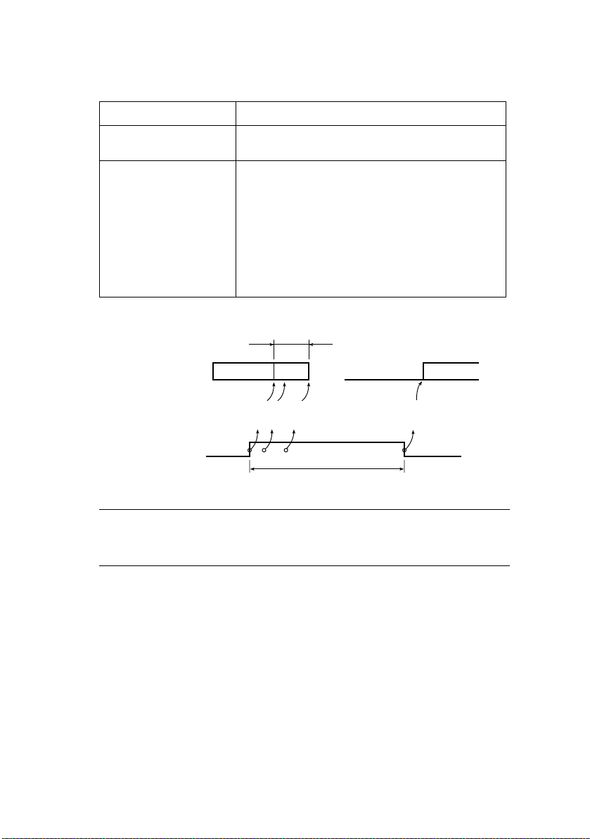
ARALLEL INTERFACE TIMING CHART
DATA BIT1 to
DATA BIT8
STROBE
BUSY
CKNLG
S
UPPORT MODE
240 Ω
(H)
(L)
µs
1.0
min
(H)
(L)
0.5
(H)
(L)
max
Compatible
Nibble (PnP Device ID only)
U
NIVERSAL SERIAL BUS
(USB)
µs
DATA
0.5 µs
min
+5 V
s
µ
1.0
min
T busy
µ
s
t1
t1 =1~4
t1
Universal Serial Bus Specification Revision 1.1 compliance.
Technical Reference Guide – Interface specifications > 21
Page 22

C
ONNECTORS
Printer Side:
“B” Receptacle (Upstream Input to the USB Device)
Cable Side:
Series “B” Plug
C
ABLE
Length:
Max. 5 m (Cable must be shielded and meet the USB Spec
Rev 2.0 for normal operation.)
The cable is not supplied with the printer.
USB
INTERFACE SIGNALS
CONTACT NUMBER SIGNAL NAME
1 Vbus (Not Used)
2 D-
3 D+
4 GND
Shell Shield
NOTE
Connector pin arrangement for above:
2
1
34
Technical Reference Guide – Interface specifications > 22
Page 23

M
ODE AND CLASS OF DEVICE
Full-speed driver
Self-powered device
D
ATA SIGNALLING RATE
Full-speed function – 12 Mb/s
Technical Reference Guide – Interface specifications > 23
Page 24

I
NTERFACE CIRCUIT
S
IGNAL LEVEL
TxD+
TxD-
Full-speed
Buffer
+ 3.3V
Rs
Rs
Input/output level
PARAMETER SYMBOL MIN. MAX. UNITS
Input levels:
High (driven) V
High (floating) V
Low V
IH
IHZ
IL
Output levels:
Low OL 0.0 0.3 V
High (driven) OH 2.8 3.6 V
Output signal crossover
voltage
V
CRS
2.0 V
2.7 3.6 V
0.8 V
1.3 2.0 V
Technical Reference Guide – Interface specifications > 24
Page 25

Signalling levels
Bus State
Required Acceptable
Differential “1” (D+)-(D-)> 200mV and D+ > V
Differential “0” (D-)-(D+)> 200mV and D- > V
Single-ended 0 (SE0) D+ and D- < V
(max) D+ and D- < VIH(min)
IL
Signalling Levels
(min) (D+)-(D-)> 200mV
IH
(min) (D-)-(D+)> 200mV
IH
Data J state:
Low-speed
Full-speed
Differential “0”
Differential “1”
Data K state:
Low-speed
Full-speed
Differential “1”
Differential “0”
Idle state:
Low-speed
Full-speed
D- > V
(min) and D+ < VIL(max)
IHZ
D+ > V
(min) and D- < VIL(max)
IHZ
D- > V
(min) and D+ < VIH(min)
IHZ
D+>V
(min) and D- < VIH(min)
IHZ
Resume state Data K state
Start-of-
Data lines switch from Idle to K state
Packet (SOP)
End-of-Packet (EOP)
Disconnect
SE0 for ≥ 1 bit time1followed by a J
state for 1 bit time
SE0 for ≥ 2.5µs
SE0 for ≥ 1 bit time1followed by a J
state
(at downstream port)
Connect
Idle for ≥ 2ms Idle for ≥ 2.5µs
(at downstream port)
Reset D+ and D- < V
(max) for ≥ 10ms D+ and D- < VIL(max) for ≥ 2.5µs
IL
NOTE
The width of EOP is defined in bit times relative to the device
type receiving the EOP. The bit time is approximate.
Technical Reference Guide – Interface specifications > 25
Page 26

T
IMING CHART
Packet voltage levels
VOH(min)
VIH(min)
VIL(max)
VOL(max)
VSS
Bus Idle
SOP
VOH(min)
VIH(min)
VIL(max)
VOL(max)
VSS
Disconnect detection
First Bit
of Packet
Last Bit
of Packet
SE0
Portion
of EOP
Bus Driven to
J State at end
of EOP
Bus Floats
Bus Idle
VSS
D+/D-
VIL
D-/D+
Device
Connected
VIHZ(min)
Full-speed device connect detection
Device
Connected
D+
VIH
D-/D+
VSS
Technical Reference Guide – Interface specifications > 26
‡2.5
‡2.5µs
µs
D-
Connect
Detected
Disconnect
Detected
Page 27

Differential data jitter
TPERIOD
Differential
Data Lines
(VCRS)
Crossover
Points
Consecutive
Transitions
*
TPERIOD + TxDJ1
N
N
Paired
Transitions
*
TPERIOD + TxDJ2
TPERIOD = 12Mbps(–0.25%)
TxDJ1 = Min-3.5ns~Max3.5ns
TxDJ2 = Min-4ns~Max4ns
Differential-to-EOP transition skew and EOP width
Crossover
TPERIOD
Differential
Data Lines
Crossover
Diff. Data-to-
SE0 Skew
*
TPERIOD + TxDEOP
N
Point
Extended
Source EOP Width: TFEOPT (160ns~175ns)
Receiver EOP Width: TFEOPT (80ns)
Receiver jitter tolerance
TPERIOD
Differential
Data Lines
}
TxJR
}
Consecutive
*
N
TPERIOD + TxDJ1
Transitions
Paired
*
TPERIOD + TxJR2
N
}
Transitions
TxJR1
TxJR1 = Min-18.5ns~Max18.5ns
TxJR2 = Min-9ns~Max9ns
TxDEOP = -2ns~5ns
TxJR1
Technical Reference Guide – Interface specifications > 27
Page 28

RS-232C
I
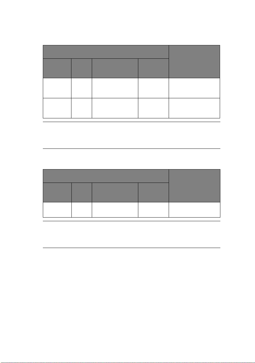
NTERFACE SIGNALS
SERIAL INTERFACE SPECIFICATIONS
PIN
SIGNAL CODE SIGNAL FUNCTION
NO.
1 Protective Ground PG — Frame ground
2 Transmitted Data TD From printer Data from
3 Received Data RD To printer Data to printer
4
Note 2
7 Signal Ground SG — Signal ground
11
Note 2
20
Note 2
5, 8 to
10, 12
to 19,
21 to 25
Request to Send RTS From printer Signal to
Supervisory Send
Data
Data Terminal
Ready
— — — Unused
SSD From printer Signal to
DTR From printer Signal to
printer
indicate printer
cannot receive
data in printer
Busy/Ready
protocol
indicate printer
cannot receive
data in printer
Busy/Ready
protocol
indicate printer
cannot receive
data in printer
Busy/Ready
protocol
NOTE
1. Connector pin arrangement for above:
13
25
Technical Reference Guide – Interface specifications > 28
1
14
(Viewed from interface cable side)
Page 29

E
LECTRICAL CHARACTERISTICS
Signal levels
RS-232C interface signal levels are as specified below, and meet
the EIA Standard RS-232C:
–15 to –3 V: LOW = OFF = LOGIC “1”
+15 to + 3 V: HIGH = ON = LOGIC “0”
Line driver
Equivalent to HIN202
400
INPUT
+5V
OUTPUT
OUTPUT
NOTE
The above figures are the standard values for a load of
3 Kohm, 15 pF and a driver source level of ±9 V.
Line receiver
INPUT
INPUT
NOTE
If the power on the input side is OFF, the output of the
receiver becomes high (+2.4 V or more) at TTL level.
Equivalent to HIN202
5 K
+3V
-3V
OUTPUT
+3V
-3V
+9V
-9V
+12V
-12V
Technical Reference Guide – Interface specifications > 29
Page 30

I
NTERFACE TIMING CHARTS
SSD signal timing chart
Data
RD
HIGH
LOW
SSD
BUSY
READY
R
ECEIVING MARGIN
Stop bit
0.5 bitStart bit
MAX 5 ms
Receiving margin is more than 37% at any baud rate.
D
ESCRIPTION OF COMMUNICATION PROCEDURES
Three types of protocol can be selected by menu communication
procedures:
> DTR
> X-ON/X-OFF
> DTR and X-ON/X-OFF
I
NTERFACE CONTROL CODE
The following function codes are used in the high-speed serial
interface:
COMMAND CODE
DC1 (17)D (11)H
DC3 (19)D (13)H
Technical Reference Guide – Interface specifications > 30
Page 31

NOTE
Characters to be printed according to the parity error
indication code (40)H will differ depending on the setting of
the printer character set. Refer to the printer User’s Guide.
Ready/Busy protocol
Block format Free
Error indication The parity error indication is printed as character
40(H).
Busy state indication The busy signal turns on (becomes Busy) when the
space in the interface buffer has become less than
256 bytes. The busy signal turns off (becomes
Ready) after 200 ms or 1 second has passed if 256
bytes have recovered within 200 ms or 1 second. If
the recovery time exceeds 200 ms or 1 second, the
busy signal turns off (becomes Ready) immediately
after the recovery has occurred.
Timing chart
RD DATA 1 DATA 2
Threshold of the
characters in
the buffer
SSD
8K
512
0
ON (BUSY)
OFF (READY
200 ms or 1 second minimum
Technical Reference Guide – Interface specifications > 31
Page 32
X-ON/X-OFF protocol
Block format Free
Error indication The parity error indication character is converted
into code 40(H).
Busy state indication The DC3 will be sent to the transmission side
immediately after the space in the interface buffer
has become less than 256 bytes to indicate that
receiving is impossible. The transmission of the
DC3 stops when data receiving has stopped. If the
recovery time for 256 bytes is within 200 ms or
1 second after the DC3 is sent, DC1 will be sent
200 ms or 1 second after the recovery to indicate
that receiving is possible. If the recovery time
exceeds 200 ms or 1 second, the DC1 is sent
immediately after the recovery has occurred.
Timing chart
256 characters or less
RD
TD PRINTING
BUSY state
ON
OFF
DATA 1
3
3-C
3
-
-CD
CD
D
200 ms or 1 second minimum
NOTE
If data is transferred when the printer is still BUSY, the printer
sends a DC3 code every time it receives data.
Waiting for BUSY
state to be free
DATA
1CD
L
OCAL TEST FUNCTION
Circuit Test mode setting
Diagnostic: Test set by menu
Technical Reference Guide – Interface specifications > 32
Page 33

Test connector: Connect the test connectors as shown below to
the interface connectors.
2
TD
3
RD
4
RTS
11
Equivalent to Cannon DB-25P
SSD
DTR
20
Circuit Test mode function
After the settings outlined in Circuit Test mode setting are
completed and power is turned on, the serial interface checks the
message buffer memory and interface driver and receiver
circuits, then prints all characters. To start and stop this test,
press the SEL switch on the front of the printer. Details of this
test are explained below.
1. Print the program revision with two numerical characters.
2. Print “LOOP TEST.”
3. Check memory for message buffer.
Print “GOOD” if memory check is OK, and print “BAD” if
memory check fails.
4. Transmit characters from code 20H to 7FH by TD signals.
At the same time, characters are received from the RD
signal and stored in the message buffer.
5. Print the characters that were stored in the message
buffer as indicated in Step 4.
6. Repeat from Step 1.
Technical Reference Guide – Interface specifications > 33
Page 34
O
PERATOR INTERFACE
O
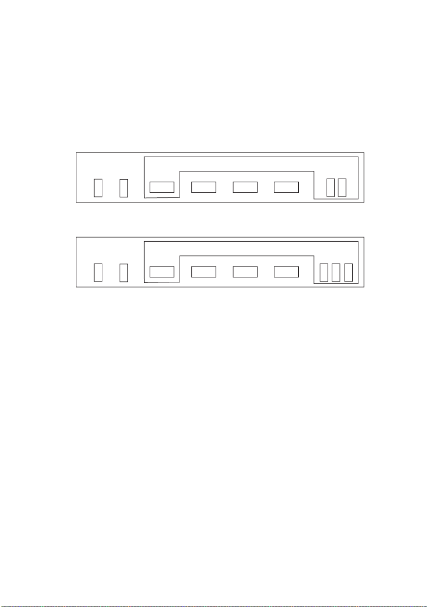
PERATOR PANEL FUNCTIONS
The operator panel button switches and lamps are located as
follows:
ML1120
PITCH
SPEED
STATUS
SEL ALARM
SEL
FONT
LF/FF LOAD/EJECT TEAR
ML1190
PITCH
SPEED
STATUS
SEL ALARM
SEL
FONT
LF/FF LOAD/EJECT TEAR
Button switch functions depend on the printer state which can be
any one of:
> Print Mode (for a summary of print modes and features
see “Appendix B – Print modes/features” on page 178.)
> Hex Dump Mode
> Menu Mode
> Tes t Mo de
> Power-On Mode
> Maintenance Mode 1 (not for use by general users)
> Maintenance Mode 2 (not for use by general users)
Technical Reference Guide – Operator interface > 34
Page 35
P
RINT MODE
PRINTER STATE
SWITCH
SEL Sets printer off-line Sets printer off-line
LF/FF Performs a line feed Performs a line feed
LOAD/EJECT Feeds forms or loads
TEAR Feeds paper to the tear
SEL + LF/FF Selects font type Selects font type
SEL + LOAD/EJECT Selects font pitch Selects font pitch
SEL + TEAR Selects print speed
LF/FF + LOAD/EJECT Invalid Invalid
LF/FF + TEAR Invalid Invalid
LOAD/EJECT + SEL Selects compress rate Microfeed down 0.366
LOAD/EJECT + LF/FF Store print position data
LOAD/EJECT + TEAR Reset the printer
TEAR + SEL Microfeed down (see
SELECT
CONT. FORMS CUT-SHEET
paper
or print position
in EEPROM
“NOTE” on page 39):
ML1120: 0.366 mm (1/
144 in) step.
ML1190: 0.555 mm (1/
180 in) step.
Ejects paper
Invalid
mm (1/144 in) step.
Microfeed up 0.366 mm
(1/144 in) step.
TEAR + LF/FF Microfeed up (see
TEAR + LOAD/EJECT Invalid Invalid
SEL + LF/FF +LOAD/
EJECT
Technical Reference Guide – Operator interface > 35
“NOTE” on page 39):
ML1120: 0.366 mm (1/
144 in) step.
ML1190: 0.555 mm (1/
180 in) step.
Invalid Invalid
Page 36

PRINTER STATE
SELECT
SWITCH
TEAR + LF/FF + SEL Invalid Invalid
TEAR + LOAD/EJECT +
SEL
TEAR + LOAD/EJECT +
LF/FF
CONT. FORMS CUT-SHEET
Invalid Invalid
Invalid Invalid
NOTE
While holding down the TEAR button, press the SEL or LF/FF
button to perform fine feed of paper. This allows for slight
movements of the paper in order to reach the cut-off position.
PRINTER STATE
SWITCH
SEL Sets printer on-line Sets printer on-line
LF/FF Performs a line feed Performs continuous
LOAD/EJECT Feeds forms or loads
TEAR Feeds paper to the tear
DESELECT
CONT. FORMS CUT-SHEET
line feeding.
Ejects the cut sheet.
paper
or print position
Feeds forms or ejects
paper
Invalid
SEL + LF/FF Selects font type Selects font type
SEL + LOAD/EJECT Selects font pitch Selects font pitch
SEL + TEAR Selects print speed
LF/FF + LOAD/EJECT Invalid Invalid
LF/FF + TEAR Invalid Invalid
LOAD/EJECT + SEL Selects compress rate Microfeed down:
ML1120: 0.366 mm (1/
144 in) step.
ML1190: 0.555 mm (1/
180 in) step.
Technical Reference Guide – Operator interface > 36
Page 37
PRINTER STATE
DESELECT
SWITCH
LOAD/EJECT + LF/FF Store print position data
LOAD/EJECT + TEAR Reset the printer
TEAR + SEL Microfeed down (see
TEAR + LF/FF Microfeed up (see
TEAR + LOAD/EJECT Invalid Invalid
SEL + LF/FF +LOAD/
EJECT
TEAR + LF/FF + SEL Invalid Invalid
TEAR + LOAD/EJECT +
SEL
TEAR + LOAD/EJECT +
LF/FF
CONT. FORMS CUT-SHEET
in EEPROM
“NOTE” on page 39):
ML1120: 0.366 mm (1/
144 in) step.
ML1190: 0.555 mm (1/
180 in) step.
“NOTE” on page 39):
ML1120: 0.366 mm (1/
144 in) step.
ML1190: 0.555 mm (1/
180 in) step.
Invalid Invalid
Invalid Invalid
Invalid Invalid
Microfeed up:
ML1120: 0.366 mm (1/
144 in) step.
ML1190: 0.555 mm (1/
180 in) step.
HEX D
UMP MODE
, M
ENU MODE
, T
EST MODE
SWITCH MENU TYPES
SEL LF/FFLOAD/EJECT TEAR
X O X X Activates Self Test
Technical Reference Guide – Operator interface > 37
mode
Page 38

SWITCH MENU TYPES
SEL LF/FFLOAD/EJECT TEAR
XOO X Performs skip/
O O X X Activates Rolling
O X O X Activates Hex Dump
O X X X Activates Menu mode
O X X X Sets Menu factory
O O X X Activates Maintenance
O O X O Activates Maintenance
continuous pattern
ASCII (1 page) when
pressed and printer
powered ON
mode
default setting
Mode 1
(Note 1)
Mode 2
(Note 1)
NOTE
When a Maintenance Mode is launched, the SEL lamp
lights and waits for the switch to be pressed.
Technical Reference Guide – Operator interface > 38
Page 39
M
AINTENANCE MODE
SWITCH MENU TYPES
SEL LF/FFLOAD/EJECT TEAR
1
X O Activates
X O Activates
NOTE
The above mode appears by pressing and holding down the
switch marked X and then pressing the switch marked O.
M
AINTENANCE MODE
SWITCH MENU TYPES
SEL LF/FFLOAD/EJECT TEAR
X O Activates Flash
NOTE
The above mode appears by pressing and holding down the
switch marked X and then pressing the switch marked O.
2
Maintenance Menu
mode
Registration Menu
mode
Loading mode
PECIAL SWITCH OPERATIONS
S
Hex Dump mode
> Enter Hex Dump mode by pressing the SEL + LOAD/EJECT
buttons at power ON.
> Exit Hex Dump mode by switching the printer OFF.
Technical Reference Guide – Operator interface > 39
Page 40

> The function of the other buttons does not change, that is,
the SEL, LF/FF, LOAD/EJECT and TEAR buttons all have
the same function as when in normal print mode.
> For more information, see “Hexadecimal Dump mode” on
page 61.
Self Test mode
> Enter Self Test mode by pressing the LF/FF + LOAD/EJECT
buttons at power ON.
> Exit Self Test mode by switching the printer OFF.
> For more information, see “Self test printing” on page 59.
Rolling ASCII mode
> Enter Rolling ASCII mode by pressing the LOAD/EJECT +
TEAR buttons at power ON.
> Exit Rolling ASCII mode by switching the printer OFF.
> For more information, see “Rolling ASCII self test printing”
on page 60.
Continuous fine line feed
> To carry out a continuous fine line feed, press SEL to set
the printer offline and then press the following buttons:
Forward: LOAD/EJECT + SEL
Reverse: LOAD/EJECT + LF/FF
> Continuous fine line feed is used to adjust the auto TOF
position.
Technical Reference Guide – Operator interface > 40
Page 41
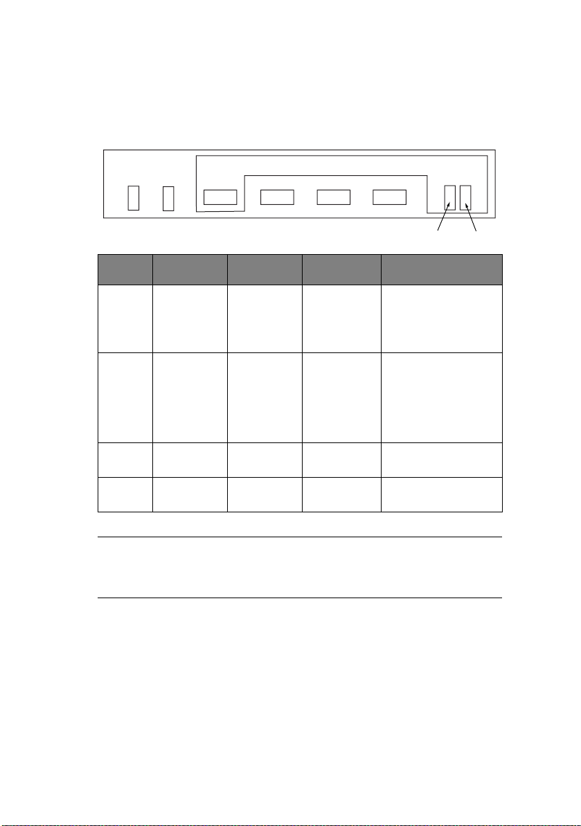
FL
AMP FUNCTIONS
ML1120
PITCH
SPEED
STATUS
SEL ALARM
SEL
FONT
LF/FF LOAD/EJECT TEAR
1
LAMP COLOUR ON OFF BLINKING
SEL Green SELECT
ALARM Red Paper end
1 Green MENU
3 Green Power ON
(data
receiving
enable)
state
state
mode
state
NOTE
In recovery impossible alarm state, both SEL and ALARM
lamps are blinking.
DESELECT
(data
receiving
impossible)
state
Paper
present.
Normal print
mode
Power OFF
state
Recovery impossible
alarm state (Note 1).
Keep printing data
state.
Cut sheet removal
standby state.
Recovery impossible
alarm state (Note 1).
Paper jam state.
Media switching
alarm state.
LF/FF and SP motor
protecting alarm.
Power save mode
(1s ON/1s OFF).
2
Technical Reference Guide – Operator interface > 41
Page 42

ML1190
PITCH
SPEED
STATUS
SEL ALARM
SEL
FONT
LF/FF LOAD/EJECT TEAR
1
LAMP COLOUR ON OFF BLINKING
SEL Green SELECT
ALARM Red Paper end
1 Green MENU
2 Green Quiet print
3 Green Power ON
(data
receiving
enable)
state
state
mode
mode
state
DESELECT
(data
receiving
impossible)
state
Paper
existing
state
Normal print
mode
Normal print
mode
Power OFF
state
Recovery impossible
alarm state (Note 1).
Keep printing data
state.
Cut sheet removal
standby state.
Recovery impossible
alarm state (Note 1).
Paper jam state.
Media switching
alarm state.
LF/FF and SP motor
protecting alarm.
High multipart print
mode.
Power save mode
(1s ON/1s OFF).
3
2
NOTE
In recovery impossible alarm state, both SEL and ALARM
lamps are blinking.
Technical Reference Guide – Operator interface > 42
Page 43
A
LARM/ERROR INDICATIONS
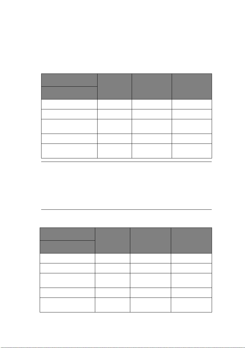
R
ECOVERABLE ALARMS
ML1120
LED SEL ALARM MENU
ALARM
Paper End R O R
Paper Lever B R
Paper Jam (Load jam,
Ejection jam)
Head Temperature R R B
SPACE/LF/FF MOTOR
Tem p e ratu r e
RR B
NOTE
O: LED continuously ON
B: LED blinking (500 ms ON, 500 ms OFF)
R: Current LED indication retained
Blank: LED OFF
BR
ML1190
LED SEL ALARM MENU
ALARM
Paper End R O R
Paper Leve r B R
Paper Jam (Load jam,
Ejection jam)
Head Temperature R R B
SPACE/LF/FF MOTOR
Tem p e ratu r e
Technical Reference Guide – Operator interface > 43
RR B
BR
Page 44

NOTE
O: LED continuously ON
B: LED blinking (500 ms ON, 500 ms OFF)
R: Current LED indication retained
Blank: LED OFF
U
NRECOVERABLE ALARMS
Unrecoverable alarms are shown below. The numbers of blinks of
the alarms indicate the states of the alarms.
Alarm indication consists of main blinking and sub-blinking. Main
blinking is the concurrent blinking of the SEL and ALARM LEDs
and sub-blinking is the blinking of only the SEL LED.
ALARM INDICATION ALARM CONTENTS
MAIN BLINKING SUB-BLINKING
1 1 Head homing alarm
2 Spacing alarm
3 Roller alarm
2 1 Program ROM alarm
2 CG ROM alarm
3 Flash ROM alarm
3 1 DRAM alarm
Technical Reference Guide – Operator interface > 44
Page 45

ALARM INDICATION ALARM CONTENTS
MAIN BLINKING SUB-BLINKING
4 1 CPU (inside RAM) alarm
2 Manual reset alarm
3 NMI alarm
4 CPU address alarm
5 DMA address alarm
6 General invalid
7 Slot alarm
8 Watchdog timer alarm
instruction alarm
9 Invalid interrupting
5 1 F/W alarm
91Head A/D error
alarm
LED blink time periods
SEL
ALARM
M
ENU SELECTION
O
VERVIEW
ON
OFF
ON
OFF
T1 T2
Main blinking
T1=T2=250 msec T3=T4=750 msec
T3
T1 T2
T4
Sub-blinking
1 Cycle
Features selected in Menu mode become the default features for
the printer each time it is powered on. The Menu function allows
Technical Reference Guide – Operator interface > 45
Page 46

features to be activated without the use of a software command
but software commands override Menu settings.
NOTE
Maintenance Menu items are not accessible to day-to-day
users.
B
UTTON SWITCH FUNCTIONS
SWITCH FUNCTION
SEL Moves forward through a group of menu items.
TEAR + SEL Moves backward through a group of menu items.
LF/FF Moves forward through the menu items.
TEAR + LF/FF Moves backward through the menu items.
LOAD/EJECT Moves forward through the values of a menu item.
TEAR + LOAD/EJECT Moves backward through the values of a menu
TEAR + LOAD/EJECT +
SEL
O
PERATION
When the last group is selected, the first group will
come up on pressing SEL.
When the first group is selected, the last group will
come up on pressing SEL.
When the last item is selected, the first item will
come up on pressing LF/FF.
When the first item is selected, the last item will
come up on pressing TEAR + LF/FF.
When the last value is selected, the first value will
come up on pressing LOAD/EJECT.
item.
When the first value is selected, the last value will
come up on pressing TEAR + LOAD/EJECT.
Exits the Menu mode.
The printer enters the initial state as at power on.
1. To enter Menu Mode:
If the printer power is OFF, while holding down the SEL
button turn the power ON.
Technical Reference Guide – Operator interface > 46
Page 47

To enter Maintenance Menu mode.
(a) Hold down the SEL, LF/FF and LOAD/EJECT buttons
and turn the power ON to activate Maintenance
Mode.
(b) After Maintenance Mode is enabled, hold down the
TEAR and LF/FF buttons and press the SEL button.
2. On entering the Menu mode, “Menu Print?” is printed.
3. See “Button switch functions” on page 46 for a description
of how to navigate the menus.
4. To exit the Menu mode, hold down the TEAR and LOAD/
EJECT buttons and press the LF/FF button.
The TOF position is not affected by Menu mode. (However,
TOF setting is executed if page length changes.)
NOTE
When entering/exiting Menu Mode, the user is not prompted.
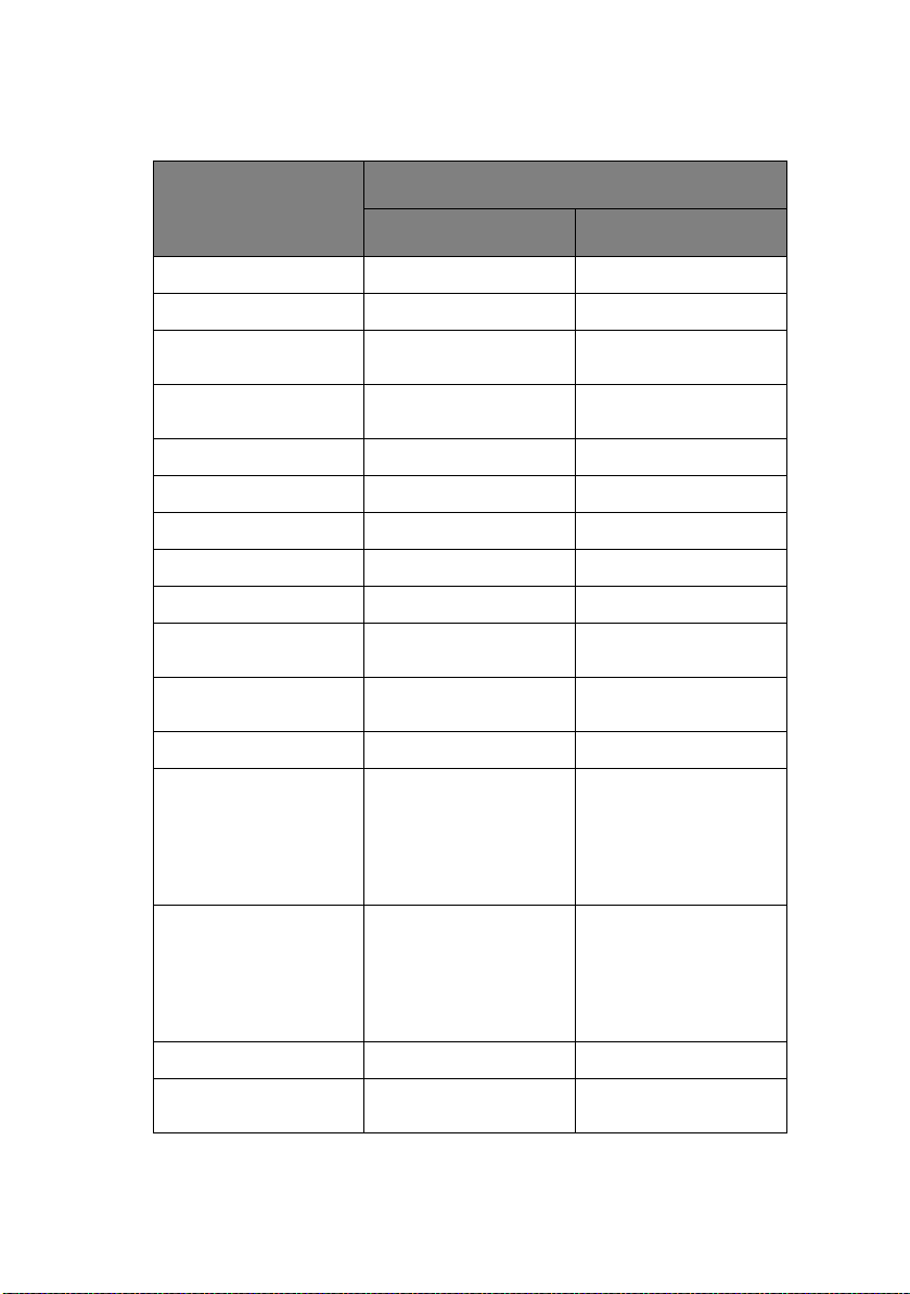
M
ENU ITEMS
In the menu settings tables below, factory default settings are
shown emboldened.Menu items and settings
In the menu settings tables below, factory default settings are
shown in bold.
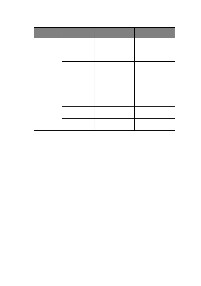
MENU ITEM FUNCTION SETTING
Printer
control menu
Emulation
Mode
Technical Reference Guide – Operator interface > 47
Select EPSON
mode, IBM mode, or
ML mode.
IBM
EPSON
ML
Page 48
MENU ITEM FUNCTION SETTING
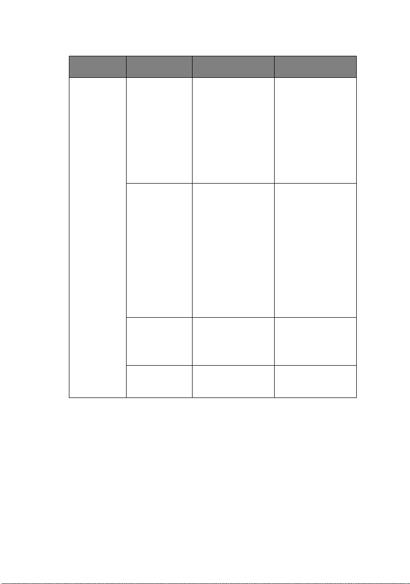
Font menu Print Mode Select quality of
Draft Mode Select HSD or SSD. HSD
Pitch Select character
Proportional
Spacing
Style Select either font
Size Select the character
ANK characters.
pitch.
Select whether to
use proportional
spacing or not.
style.
scale size.
NLQ Courier
NLQ Gothic
NLQ OCR-B
DRAFT
Utility
SSD
10 CPI, 12 CPI, 15
CPI, 17.1 CPI, 20
CPI
Yes
No
Normal, Italics
Single, Double
Technical Reference Guide – Operator interface > 48
Page 49

MENU ITEM FUNCTION SETTING
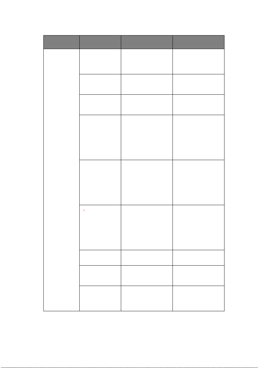
Symbol sets
menu
Character Set Select either ANK
Language Set Select a language
Zero Character Select either print
character code
table.
character set.
font pattern to
receive a zero
character located at
30H in ANK code or
at AA30H in a
single-byte code.
Standard
Line Graphics
Block Graphics
(displayed for ML
emulation only)
Set I
Set II (displayed for
IBM and EPSON
emulation only)
ASCII, French,
German, British,
Danish I, Swedish I,
Italian, Spanish I,
Japanese,
Norwegian, Danish
II, Spanish II, Latin
American, French
Canadian, Dutch,
TSR80, Swedish II,
Swedish III,
Swedish IV, Turkish,
Swiss I, Swiss II,
Publisher
Unslashed
Slashed
Technical Reference Guide – Operator interface > 49
Page 50

MENU ITEM FUNCTION SETTING
Symbol sets
menu
Code Page Select a code page. USA
Slashed Letter 0 Set whether to
convert slashed 0
located at 9BH and
9DH in USA code
page or not.
Canada French
Multilingual
Portugal
Norway
Tur key
Greek_437
Greek_869
Greek_928
Grk_437 CYPRUS
Polska Mazovia
Serbo Croatic I
Serbo Croatic II
ECMA-94
Hungarian CWI
Windows Greek
Windows East
Europe Windows
Cyrillic
East Europe Latin
II-852
Cyrillic I-855
Cyrillic II-866
Kamenicky(MJK)
ISO Latin 2
Hebrew NC (862)
Hebrew OC
Turkey_857
Latin 5 (Windows
Tur key )
Windows Hebrew
Ukrainian
Bulgarian
ISO Latin 6 (8859/
10) Windows Baltic
Baltic_774
KBL-Lithuanian
Cyrillic Latvian
Roman-8
Icelandic-861
Multilingual 858
ISO 8859-15
Greek_737
Asmo449+
Asom708
Arabic864
Windows Arabic
Yes
No
Technical Reference Guide – Operator interface > 50
Page 51

MENU ITEM FUNCTION SETTING
Rear feed
menu
Line Spacing Select line feed
Form Tear-Off Select manual or
Skip Over
Perforation
Page Length Select the length of
pitch.
auto as the method
to advance a
continuous form to
the form tear-off
position.
Select whether to
skip over
perforation or not.
(When a skip over
perforation setup
command is
received, the
received command
is given priority.)
a continuous form.
6 LPI
8 LPI
Off
500 ms
1 sec
2 sec
Yes (25.4 mm/ 1 in)
No
279.4 mm(11 in)
296.3 mm(11 2/3
in)
304.8 mm (12 in)
355.6 mm(14 in)
431.8 mm(17 in)
127.0 mm(5 in)
76.2 mm(3 in)
82.6 mm(3.25 in)
84.7 mm(10/3 in)
93.1 mm(11/3 in)
101.6 mm(4 in)
139.7 mm(5.5 in)
152.4 mm(6 in)
177.8 mm(7 in)
203.2 mm(8 in)
215.9 mm(8.5 in)
Initial Position
(Paper position
when power
on)
Cut position
adjust
Technical Reference Guide – Operator interface > 51
This is the position
of the paper when
the paper is already
loaded at power on.
(For continuous
form mode only.)
Select an
adjustment value
for the position to
cut the end of a
continuous form.
(In 1/90 in
increments)
Print
Tear OFF
-20 – -1
0
+20 – +1
Page 52
MENU ITEM FUNCTION SETTING
Rear feed
menu
TOF
adjustment
(continuous)
TOF
(continuous)
Continuous
paper LF adjust
Centring for
paper top
(continuous)
Select an
adjustment value
for the reference
position in regard to
the TOF position of
a continuous form.
The position moves
to the rear of the
form by [+] and to
the top of the form
by [-] in 1/60 in
increments.
Select the reference
position for the TOF
position when auto
loading continuous
form paper from the
rear of the printer.
(Up to the midsection of
characters in the
first line.)
Select an
adjustment value
for the line feed
position.
Find centre position Valid
-20 – -1
0
+20 – +1
2.12 mm (1/12 in)
4.23 mm (1/6 in)
6.35 mm (1/4 in)
8.47 mm (1/3 in)
10.58 mm (5/12 in)
12.7 mm (1/2 in)
14.82 mm (7/12 in)
16.93 mm (2/3 in)
19.05 mm (3/4 in)
21.17 mm (5/6 in)
23.28 mm
(11/12 in)
25.4 mm (1 in)
27.52 mm
(13/12 in)
Use top of form
-2
-1
0
+1
+2
Invalid
Technical Reference Guide – Operator interface > 52
Page 53

MENU ITEM FUNCTION SETTING
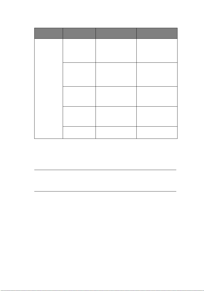
Bottom feed
menu
Top f e e d
menu
Line Spacing Select line feed
Skip Over
Perforation
Page Length Select the length of
Line Spacing Select line feed
Page Length Select the page
pitch.
Select whether to
skip over
perforation or not.
(When a skip over
perforation setup
command is
received, the
received command
is given priority.)
a continuous form.
pitch.
length of cut paper.
6 LPI
8 LPI
Yes (25.4 mm/1 in)
No
279.4 mm(11 in)
296.3 mm
(11 2/3 in)
304.8 mm (12 in)
355.6 mm(14 in)
431.8 mm(17 in)
127.0 mm(5 in)
76.2 mm(3 in)
82.6 mm(3.25 in)
84.7 mm(10/3 in)
93.1 mm(11/3 in)
101.6 mm(4 in)
139.7 mm(5.5 in)
152.4 mm(6 in)
177.8 mm(7 in)
203.2 mm(8 in)
215.9 mm(8.5 in)
6 LPI
8 LPI
279.4 mm(11 in),
296.3 mm
(11 2/3 in)
304.8 mm (12 in)
355.6 mm(14 in)
431.8 mm(17 in)
127.0 mm(5 in)
76.2 mm(3 in)
82.6 mm(3.25 in)
84.7 mm(10/3 in)
93.1 mm(11/3 in)
101.6 mm(4 in)
139.7 mm(5.5 in)
152.4 mm(6 in)
177.8 mm(7 in)
203.2 mm(8 in)
215.9 mm(8.5 in)
Technical Reference Guide – Operator interface > 53
Page 54

MENU ITEM FUNCTION SETTING
Top f e e d
menu
Top feed wait
time
Page length
control
Cut sheet auto
eject Position
TOF
Adjustment
(Cut Sheet)
TOF (cut sheet
top of form)
Cut sheet LF
adjustment
Select the waiting
time between
setting paper on the
tray and feeding it
while the printer is
waiting for paper to
be fed in cut-paper
manual feed mode.
Control the page
length of cut paper.
Select a printable
area at the bottom
of cut sheets of
paper in cut-paper
mode (the character
centre position).
Select an
adjustment value
for the reference
position in regard to
the TOF position of
cut-paper/
passbooks.
The position moves
to the rear of the
form by [+] and to
the top of the form
by [-] in 1/60 in
increments.
Select the reference
position for the TOF
position when
feeding cut-paper in
manual mode. (Up
to the mid-section
of characters in the
first line.)
Adjust a line feed
amount in cut-paper
mode.
Invalid
500 ms
1 sec
2 sec
by MENU setting
by Actual page
length
6.35 mm (1/4 in)
12.70 mm(6/12 in)
14.82 mm (7/12 in)
-20 – -1
0
+20 – +1
2.12 mm (1/12 in)
4.23 mm (1/6 in)
6.35 mm (1/4 in)
8.47 mm (1/3 in)
10.58 mm (5/12 in)
12.7 mm (1/2 in)
14.82 mm (7/12 in)
16.93 mm (2/3 in)
19.05 mm (3/4 in)
21.17 mm (5/6 in)
23.28 mm (11/12
in) 25.4 mm (1 in)
27.52 mm
(13/12 in)
Use top of form
-14 – -1
0
+14 – +1
Technical Reference Guide – Operator interface > 54
Page 55
MENU ITEM FUNCTION SETTING
Set-up menu Graphics Select the printing
Receive buffer
size
Paper out
override
Print
Registration 1
Print
Registration 2
Print
Registration 3
direction when
double-height print
data exists in a line.
Select size of the
received buffer.
Select whether to
detect paper end or
not.
Adjust the print
starting position on
printing in the
reverse direction.
(The position moves
to the right or left in
1/720 in
increments.)
Adjust the print
starting position on
printing in the
reverse direction.
(The position moves
to the right or left in
1/720 in
increments.)
Adjust the print
starting position on
printing in the
reverse direction.
(The position moves
to the right or left in
1/720 in
increments.)
Bi-directional
Uni-directional
1line
32 K
64 K
No
Yes
-10 – -1
0
+10 – +1
-10 – -1
0
+10 – +1
-10 – -1
0
+10 – +1
Operator panel
function
Reset inhibit Set whether to
Print suppress
effective
Technical Reference Guide – Operator interface > 55
Select full or limited
operation.
enable or disable an
initial command.
Set whether to
enable or disable a
print suppress setup
command.
Full operation
Limited operation
No
Yes
Yes
No
Page 56
MENU ITEM FUNCTION SETTING
Set-up menu Auto LF Select whether to
Auto CR Select whether to
SI select pitch
(10 CPI)
SI select Pitch
(12 CPI)
Time out print Select valid or
I
NITIALISING MENU SETTINGS
perform auto LF
operation or not
upon receiving a CR
code.
perform auto CR
operation upon
receiving a carriage
return command.
Set how to handle
an SI command
received in 10 CPI
mode.
Set how to handle
an SI command
received in 12 CPI
mode.
invalid.
Yes
No
Yes
No
15 CPI
17.1 CPI
12 CPI
20 CPI
Valid
Invalid
To restore the menu settings to their initial values, carry out the
steps below.
NOTE
The values adjusted by the Adjustment menus are not
initialised by the following procedure.
1. Set the Power Switch to OFF.
2. Press and hold down the SEL and LF/FF buttons together
and then set the Power Switch to ON.
Technical Reference Guide – Operator interface > 56
Page 57

A
DJUSTING
Use the following procedure to set TOF to accord with the
reference position (6.35 mm (0.25 in)). The reference position
refers to the first line of the paper i.e. the position to which the
printer feeds the paper when automatically loading the paper.
1. Print out the menu settings of the printer and confirm that
2. Set the Paper Type lever to the required paper type.
3. When continuous forms are used, place the paper on the
4. In continuous forms mode, press the LOAD/EJECT button.
5. In cut sheet mode, place the paper in the Paper Tray and
6. In off-line mode, press the following buttons to adjust the
TOF
POSITION
NOTE
Adjusting of TOF can be done in cut sheet mode or continuous
forms mode.
the TOF (in cut sheet mode or continuous forms mode) is
6.35 mm (0.25 in).
Pin Tractor.
For cut sheet mode, do not insert the paper at this stage.
press LOAD/EJECT.
As the paper is taken into the printer, press the LF/FF
button and the paper is taken into the 6.35 mm (0.25 in)
position.
first printing line:
To feed the paper forward by a small amount, press and
hold down the LOAD/EJECT button and then press the SEL
button.
Technical Reference Guide – Operator interface > 57
Page 58

To feed the paper backward by a small amount, press and
hold down the LOAD/EJECT button and then press the LF/
FF button.
NOTE
If the specified correction range is more than +- 0.366 mm
(1/144 in), the QUIET indicator flashes and the paper cannot
be moved.
When the paper is positioned at the required TOF, release
the buttons in Step 5 above.
To save this position as the TOF, press and hold down the
LOAD/EJECT and the LF/FF buttons together for 3 seconds.
NOTE
Do not turn the Platen Knob or switch off the printer during
the above procedure.
P
RINTER SPEED SETTINGS
P
RINTER IMPACT MODE
When switched ON, the printer enters the impact mode selected
in the menu. You can change this to normal speed and quiet
printing without using the menus as follows.
Normal speed printing
Use this for standard file printing operations.
1. Ensure the SEL indicator is illuminated.
2. Hold down the SEL button and press the TEAR button.
Status Indicator 2 turns off.
Quiet printing
Use this for quieter printing.
1. Ensure the SEL indicator is illuminated.
2. Hold down the SEL button and press the TEAR button.
Status Indicator 2 is illuminated.
Technical Reference Guide – Operator interface > 58
Page 59
R
EGISTRATION MENU
O
VERVIEW
This is a factory shipped configuration to adjust the horizontal
print position correction and is capable of setting the horizontal
print position.
O
PERATION
To enter registration menu mode:
1. Hold down the SEL + LF/FF switches and turn on the
power to activate the maintenance mode.
2. After the maintenance mode is enabled, hold down the
TEAR switch and press the LF/FF switch.
R
EGISTRATION DETAILS
NO ITEM SET REMARK
1 Registration
Low
2 Registration
Normal
3 Registration
High 1
4 Registration
High 2
S
ELF TEST PRINTING
1. Start:
While pressing the LF/FF switch, turn on the power.
2. Stop:
Stop the test by pressing the SEL switch.
Technical Reference Guide – Operator interface > 59
+10, +9,...0...-9, -10 Factory Shipped
Configuration:
+-10/720 in increments of
1/720 in.
Page 60

3. Print Pattern:
(a) Header:
aaaaa EI E F/W bb.cc
LD ff.gg
ddddddddYR-ee
as defined by:
POSITION &
CHAR. COUNT
aaaaa Model name ML6300FB
bb.cc Revision no. 00.00 – 99.99 Firmware revision
dddddddd Part Number 43058201 YR Number
ee Part Number 01 – 99 ROM-FD Number
ff.gg Revision no. 00.00-99.99 Boot program
DESCRIPTION DATA
PRINTED
COMMENTS
revision
(b) The first firmware revision is
‘01.xx’ (30)H(31)H(2E)H(x)H(x)H
(c) The test pattern is a consecutive printing of ASCII
characters 20H to 7EH in all print quality and pitch
combinations
NUMBER OF CHARACTERS PRINTED PER LINE
80 at 10 CPI 136 CH
96 at 12 CPI 163 CH
120 at 15 CPI 204 CH
R
OLLING
1. Start:
137 at 17.1 CPI 233 CH
160 at 20 CPI 272 CH
ASCII
SELF TEST PRINTING
Start the continuous rolling ASCII by pressing and holding
the Load/Eject and Tear buttons and then turning the
power on.
Technical Reference Guide – Operator interface > 60
Page 61

2. Stop:
Stop the test by pressing the SEL switch.
3. Print pattern:
(a) Header:
aaaaa EI E F/W bb.cc
LD ff.gg
ddddddddYR-ee
as defined by:
POSITION &
CHAR. COUNT
aaaaa Model name ML6300FB
bb.cc Revision no. 00.00 – 99.99 Firmware revision
dddddddd Part Number 43058201 YR Number
ee Part Number 01 – 99 ROM-FD Number
ff.gg Revision no. 00.00 - 99.99 Boot program
DESCRIPTION DATA
PRINTED
COMMENTS
revision
(b) Pattern will be continuous printing of all ASCII
characters.
(c) The test completes when one print pattern is printed
out.
H
EXADECIMAL DUMP MODE
O
VERVIEW
Normally a printer prints character patterns that correspond with
the input character code. The printer does not print function
codes or invalid codes. If the printer does not operate normally,
the data sent from the host computer must be checked to
determine if the commands are correct.
In this mode the printer converts input data into hexadecimal
data and prints all the input data, making it is easy to check all
the codes sent from the host computer to the printer.
Technical Reference Guide – Operator interface > 61
Page 62

O
PERATION
1. Entering Hexadecimal Dump mode:
While pressing the SEL+LOAD/EJECT switches, turn on the
power.
2. Exiting Hexadecimal Dump mode:
Turn the power OFF
3. Print pattern:
Hex Data Dump
XXXXXXXXXXXXXXXXXXXXXXXXXXXXXXXX...................
XXXXXXXXXXXXXXXXXXXXXXXXXXXXXXXX ...................
4. Printing example:
The following is an example when data is input from the
host computer in the basic format:
Basic: LPRINT CHR$ (&H1B); “0 “; CHR$ (&H1E);
“01234567890 “; CHR$ (&0D); CHR$ (&H0A)
1B 30 1E 30 31 32 33 34 35 36 37 38 39 30 OD OA
.0.01234567890.
F
UNCTION
> Prints in 10 CPI Utility mode.
> Both parallel and USB interfaces are available.
> Paper auto Skip Over Perforation (SOP) by menu default
value continuous for both. If SOP is enabled, one inch
from the bottom of the paper will not be printed.
> Printing starts when more than 16 bytes of data are
received (line full).
C
ONTINUOUS PAPER AUTO-LOADING
Load continuous paper on the tractor (at a position such that the
paper does not cross the paper-end sensor).
In this situation, pressing the LOAD/EJECT switch starts autoloading.
Technical Reference Guide – Operator interface > 62
Page 63

When the paper does not cross the paper-end sensor within an
8-in feed of the paper, a paper-end state occurs.
The print position of the first data line can be set by menu
function or in first character setting mode.
NOTE
TOF is the position that is set when the operation was
completed properly.
C
ONTINUOUS PAPER AUTO-PARKING
With continuous paper loaded in continuous paper mode,
pressing the PARK switch starts auto-parking.
When the end of continuous paper is detected by the time the
paper is fed 22 in reverse, auto-parking finishes and a paper-end
state is established.
If the end of continuous paper is not detected after a 22-in
reverse feed, auto-parking terminates. The position that is set
when the auto-parking terminated becomes TOF.
Pressing the PARK switch again repeats the auto-parking
operation.
The number of reverse movements using the switch is limited to
one.
Do not perform reverse feed if the last sheet of continuous paper
will come off the tractor.
CUT-
SHEET PAPER SEMI-AUTO-LOADING
By loading paper on the input tray in cut-sheet mode or while
waiting for cut-sheet feed, semi-auto-loading starts after the
menu-set paper feed wait time (0.5 sec/1.0 sec/2.0 sec) has
elapsed.
Once started, cut-sheet paper is fed until the print position of the
first data line is reached, the printer is placed in the SELECT state
and the operation finishes.
The TOF set at that time is the printing start position of the first
data line.
Technical Reference Guide – Operator interface > 63
Page 64

F
ORM TEAR-OFF
F
UNCTION
Form tear-off allows the user to tear the continuous forms paper
at a desired cut position by advancing the paper to the cutting
edge of the front upper cover.
SET-
UP
1. Conditions:
(a) Continuous forms paper is loaded into the tractor
feed.
2. Tea r Po s it ion :
(a) Load continuous forms paper.
Press the TEAR switch while On line to move the
paper up to tear position.
(b) Adjust to the desired tear position using fine LFs.
A
CTION
(a) The paper will advance to the tear-off position
approximately 500ms/1sec/2sec after printing.
(b) When data is received by the printer or the SEL
switch is pressed to select the printer, the paper will
retract to the user-defined printing position.
(c) Tear Up/Down operations are alternately executed
by pressing the TEAR switch.
Technical Reference Guide – Operator interface > 64
Page 65

C
OMMAND DESCRIPTIONS
For a summary of the commands available see “Appendix A –
Command summary” on page 163.
H
ORIZONTAL CONTROL
C
ARRIAGE RETURN
> Code: CR
> Compatibility:
ML1190: EPSON LQ/IBM
ML1120: EPS FX/IBM III/ML
> Function:
Terminates the print line and returns the print position to
the start of the line.
The data in the print buffer will be printed.
> Additional details:
Double width mode which is designated by SO (and ESC SO
in Epson mode) will be reset.
Auto feed XT signal low – Epson.
H
ORIZONTAL TAB SET
> Code: ESC D n1 n2 ... nj nk NUL
> Compatibility:
ML1190: EPSON LQ/IBM
ML1120: EPS FX/IBM III
> Function:
Sets the tab stops to according to the values of n, which
specify the charater tab positons starting from Epson 32
tab) and IBM (28 tab).
> Range:
Epson: k = 1 – 32
Technical Reference Guide – Command descriptions > 63
Page 66
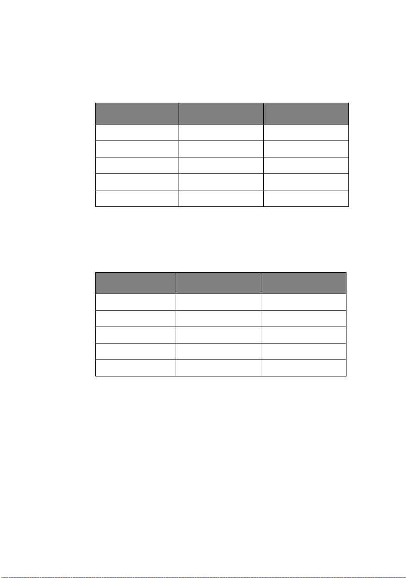
IBM: k = 1 – 28
Range n = 1 – 255
ML1190
CPI WIDE NARROW
10 135 79
12 163 95
15 203 119
17.1 233 137
20 255 159
nj < nk: valid.
nj >= nk: nk invalid – IBM, nk ignored and sequence
terminated – Epson.
ML1120
CP1 EPSON VALUE IBM VALUE
10 79 80
12 95 96
15 119 120
17.1 137 138
20 159 160
> Out of range:
If k = 0 or k > 32 – Epson, k > 28 – IBM
The last value and any following value of n will be ignored.
Maximum n value in each CPI, values larger than
maximum are ignored.
> Additional details:
The tab settings n1, n2, n3, nk must be entered in
ascending order.
Technical Reference Guide – Command descriptions > 64
Page 67

Entire command str i n g i s t e r m inated wi t h a N U L , C HR$ (0).
MODE LEFT MARGIN
CHANGE
Epson Position adjusted Position not affected
IBM Position not affected Position relative to pitch
PITCH CHANGES
Tabs are set at every eighth character after powering up
the printer, receiving an l-PRIME (INIT) signal or executing
an ESC @ (Epson mode only).
Receiving ESC } NULL signal.
Receiving ESC { n signal.
Executing Menu setting.
If n = 0, clear all tabs set.
Example: ESC D 30 40 1 10 60 70 NUL
IBM mode: 30 40 60 70 valid
Epson mode: 30 40 valid
> Related functions:
Horizontal Tab – HT
H
ORIZONTAL TAB
> Code: HT
> Compatibility:
ML1190: EPSON LQ/IBM
ML1120: EPS FX/IBM III
> Function:
This command causes a skip to the next Horizontal Tab
(HT) position.
> Additional Details:
Epson – Tabs are absolute positions; changes in character
pitch do not change tab positions.
IBM – Tabs are relative to character pitch.
Technical Reference Guide – Command descriptions > 65
Page 68

Upon power up the default tabs are set at columns 9, 17,
25, 33... and every eight spaces after that, according to
the default character pitch.
The spaces generated by a horizontal tab will not be
scored.
> Related Functions:
Horizontal tab stop set – ESC D
R
ESET TAB SETTINGS TO POWER-ON DEFAULT VALUES
> Code: ESC R
> Compatibility:
ML1190: IBM
ML1120: IBM III
> Function:
This command sets horizontal tabs at every eighth
character starting at column 9 and clears all vertical tabs.
> Additional details:
The horizontal tabs will be set according to the default
character pitch.
E
XECUTE ABSOLUTE HORIZONTAL DOT POSITION
> Code: ESC $ n1 n2
> Compatibility:
ML1190: EPSON LQ
ML1120: EPS FX
> Function:
Moves the printhead to the specified absolute horizontal
dot position in a line from the left margin; subsequent data
is printed from this position.
> Range:
In dot position setting, n1 becomes low byte and n2
becomes high byte.
Technical Reference Guide – Command descriptions > 66
Page 69

n1, n2 = 0 – 255 (bit7 of n2 is ignored).
Limit:
0 <= n1 + (n2*255) <= 10922 (0/120 – 10922/120 in)
10923 <= n1 + (n2*255) <= 21845 (0/120 – 10922/
120 in)
21846 <= n1 + (n2*255) <= 32767 (0/120 – 10921/
120 in)
> Out of range:
Any position specified beyond the right margin is ignored.
> Additional details:
Dot position = (n1 + n2*256)/60 <= 10.6 in.
The position specified as n1 = n2 = 0 is the left margin.
Dot position is absolute. The character pitch does not affect
the dot position.
This command starts print when specified dot position is
left of the current print position.
Spaces generated by moving the horizontal positioning are
not scored if score is set.
E
XECUTE RELATIVE DOT POSITION
> Code: ESC \ n1 n2
> Compatibility:
ML1190: EPSON LQ
ML1120: EPS FX
> Function:
This moves the printhead to the dot position from which all
subsequent data is to be printed, relative to the current
position in a line.
> Range:
n1 and n2 specify the dot position; the lower byte is n1 and
the upper byte is n2.
Range n1 and n2 is 0 – 255.
> Out of range:
Technical Reference Guide – Command descriptions > 67
Page 70

Defined values beyond the left or right margins are
ignored.
> Additional details:
This relative setting defines the next printing position by
calculating on the basis of the printing position
immediately preceding the input of this code. Printing
starts at a position before or after the previous position at
a dot spacing defined by the selected print mode.
Positive values move the print position to the right and
negative values move it to the left.
Dot position = n1 + n2 * 256.
Physical position = dot position/density = (n1 + n2*256)/
DPI.
With the score mode selected, score is added only for skip
to right.
Actual relative dot positioning depends on the current
mode.
Dots/line:
DPI VALUE
Utility – All CPI 120 1272
LQ – All CPI & Prop 180 1908
Example:
DOTS NUMBER N2 N1
2448 09 90
|||
|||
303
202
101
000
-1 FF FF
Technical Reference Guide – Command descriptions > 68
Page 71

DOTS NUMBER N2 N1
-2 FF FE
-3 FF FD
|||
|||
-2448 F6 70
M
OVE RIGHT RELATIVE DOT POSITION
> Code: ESC d n1 n2
> Compatibility:
ML1190: IBM
ML1120: IBM III
> Function:
Moves the print position n/120 in to the right from the
current printhead position.
> Range:
Specify dot position following n1 and n2.
n1 is low byte, n2 is high byte.
n1 and n2 range is 0 – 255
Limit 0 <= n1 + (n2*255) <= 1632
> Out of range:
Values beyond the right margin will be ignored.
> Additional details:
If score is set any horizontal positioning is scored.
M
OVE LEFT RELATIVE DOT POSITION
> Code: ESC e n1 n2
> Compatibility:
ML1190: IBM
Technical Reference Guide – Command descriptions > 69
Page 72

ML1120: IBM III
> Function:
Moves current logical horizontal position to the left (toward
home position) in steps of n/120 in. Prints data in print
buffer.
> Range:
In dot position setting, n1 becomes low byte and n2
becomes high byte.
n1, n2 = 0 – 255 (bit7 of n2 is ignored).
Limit:
0 <= n1 + (n2*255) <= 10922 (0/120 – 10922/120 in)
10923 <= n1 + (n2*255) <= 21845 (0/120 – 10922/
120 in)
21846 <= n1 + (n2*255) <= 32767 (0/120 – 10921/
120 in)
> Out of range:
Current logical horizontal position is set to the left margin
if value is entered beyond left margin.
> Additional details:
No score is added to spaces generated by this command.
L
EFT MARGIN SET
> Code: ESC I n
> Compatibility:
ML1190: EPSON LQ
ML1120: EPS FX
> Function:
Left margin is set at (n) characters from printhead home
position.
> Range:
Technical Reference Guide – Command descriptions > 70
Page 73

Range n = 0 – 255
NAME PITCH VALUE
PICA/PROPORTIONAL 10 0 – 105
ELITE 12 0 – 126
– 15 0 – 158
COMPRESSED 17.1 0 – 180
COMPRESSED ELITE 20 0 – 211
COMPRESSED Prop 20 0 – 211
> Out of range:
If n exceeds the maximum value, this command will be
ignored.
> Additional details:
The left margin is set as an absolute position according to
the current character pitch. Changes in character pitch do
not change the margin position.
The print buffer will be cleared.
Maximum difference between left margin and right margin
values is 2 characters for 5 CPI.
> Related functions:
Right margin set – ESC Q n
R
IGHT MARGIN SET
> Code: ESC Q n
> Compatibility:
ML1190: EPSON LQ
ML1120: EPS FX
> Function:
Right margin is set at (n) characters from head home
position.
> Range:
Technical Reference Guide – Command descriptions > 71
Page 74
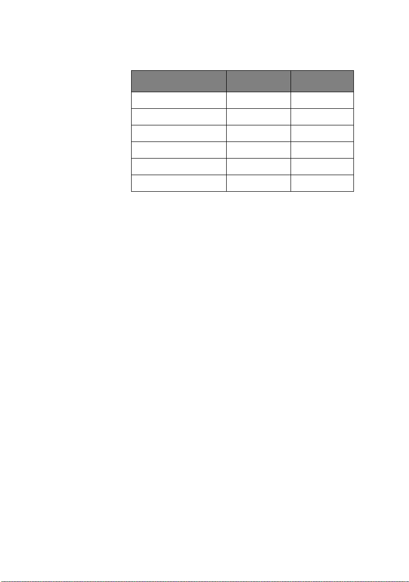
Range n = 1 – 255
NAME PITCH VALUE
PICA/PROPORTIONAL 10 1 – 106
ELITE 12 1 – 127
– 15 1 – 159
COMPRESSED 17.1 1 – 181
COMPRESSED ELITE 20 1 – 212
COMPRESSED Prop 20 1 – 212
> Out of range:
The number “n” must be within the ranges given above,
otherwise it will be ignored.
If n = 0, or is less than or equal to the left margin, this
command is ignored.
> Additional details:
The right margin is set as an absolute position, according
to the current character pitch. Changes in character pitch
do not change the margin setting.
While in proportional mode the character pitch width will
be set in pica character size. (10 CPI = 36 dots)
Any graphics after the right margin are lost.
Setting the right margin clears the print buffer.
Minimum difference between left margin and right margin
values is 5 characters for 5 CPI.
Attempting to print a character beyond the right margin
will print the character on the next line after a line feed and
carriage return are executed.
SET
LEFT/RIGHT MARGIN
> Code: ESC X n1 n2
> Compatibility:
ML1190: IBM
Technical Reference Guide – Command descriptions > 72
Page 75
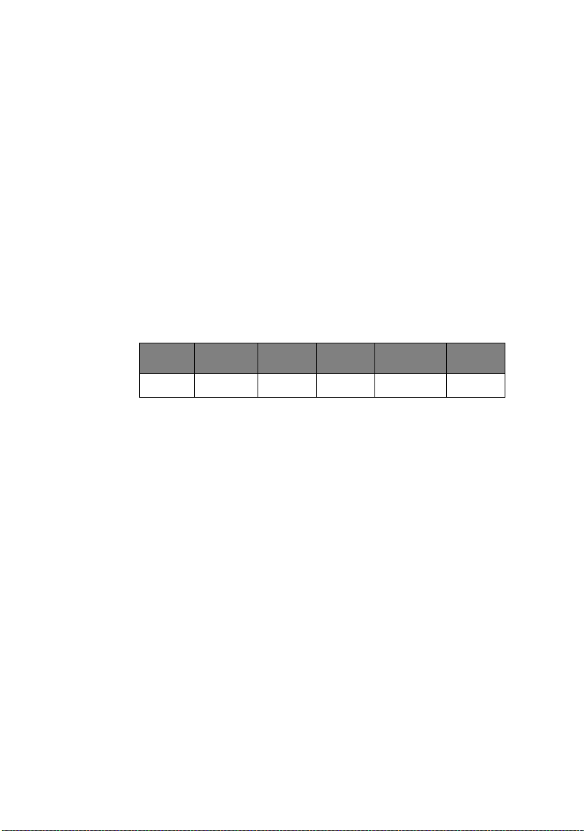
ML1120: IBM III
> Function:
Sets the left and right margins in character positions from
the home position by the current character pitch.
> Range:
The ranges for n1 and n2 are:
0 <= n1 <= 255 Left margin
0 <= n2 <= 255 Right margin
n1 < n2
> Out of range:
If n1 or n2 = 0 then the current margin setting is used.
If n2 exceeds the default range n2 will be converted to the
default value.
10 CPI 12 CPI 15 CPI 17.1 CPI 20 CPI
Value 106 127 159 181 212
> Additional details:
The default value of the left margin is the first character.
The margin settings are absolute. Changes in character
pitch do not affect the margin position.
n1, n2 indicate the left and right edges of printable area.
For example, if n1 = 10, n2 = 100, the printable area is
from the 10th column to the 100th column: 91 characters
are printable.
A
UTO JUSTIFICATION
> Code: ESC a n
> Compatibility:
ML1190: EPSON LQ
ML1120: EPS FX
> Function:
The text position/alignment will be set according to one of
the four given modes assigned by n. (n is a Binary value.)
Technical Reference Guide – Command descriptions > 73
Page 76

> Range:
N JUSTIFICATION
00H Left
01H Centre
02H Right
03H Full
> Additional details:
n = 0: Left justification is the default or standard format,
in which the left margin is justified and the right margin is
not.
n = 1: The centring command centres a line of text
between the margins. This command is used for headings,
titles and captions.
n = 2: Right justification is the opposite of left justification.
The right margin is justified and the left is not.
n =3: Full justification puts extra spaces where necessary
so that both the left and right margins are justified.
Full justification (n = 3) is performed when data exceeding
75% of printable characters in a line is received at the time
of print start.
BS, DEL, HT are invalid when auto justification is used
except when n = 0.
Print position will be affected by the commands which set
the left/right margin.
NOTE
When using full auto justification, use carriage return at the
end of paragraphs only, not at the end of each line of text.
SET/
RESET UNIDIRECTION PRINTING
> Code: ESC U n
> Compatibility:
Technical Reference Guide – Command descriptions > 74
Page 77
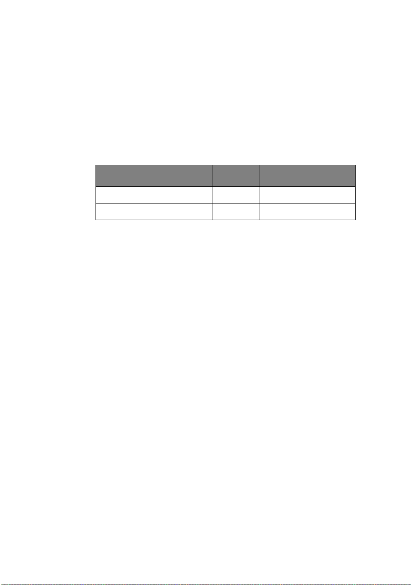
ML1190: EPSON LQ/IBM
ML1120: EPS FX/IBM III
> Function:
Unidirectional printing, from left to right, or bidirectional
printing will be performed based on the value of n.
> Range:
Range n:
EPSON IBM ACTION
01H, 31H, 81H, B1H ODD SET Unidirectional
00H, 30H, 80H, B0H EVEN RESET (Bidirectional)
> Out of range:
This command will be ignored if n equals a value other than
the values mentioned above.
> Additional details:
Short line seeking is performed in both unidirectional and
bidirectional print modes.
ONE
LINE UNIDIRECTIONAL PRINTING
> Code: ESC <
> Compatibility:
ML1190: EPSON LQ/IBM
ML1120: EPS FX/IBM III
> Function:
Unidirectional printing for one line only will be performed.
> Additional details:
The line is printed from left to right.
Subsequent lines will be printed, bidirectionally, according
to short line seeking priorities logic.
This command returns the printhead to the start of the
print line before printing begins.
Technical Reference Guide – Command descriptions > 75
Page 78

SET/
RESET HALF SPEED PRINTING
> Code: ESC s n
> Compatibility:
ML1190: EPSON LQ/IBM
ML1120: EPS FX/IBM III
> Function:
The printer starts/stops printing at 50% of normal speed
upon receipt of this command depending on the value of n.
> Range:
n = 01H, 31H, 81H, or B1H SET half-speed printing.
n = 00H, 30H, 80H, or B0H SET full speed printing.
> Out of range
This command will be ignored if n equals a value other than
the values mentioned above.
> Additional details:
Half Speed mode can be used to reduce printer noise.
If the print speed is slower than the printer’s physical
lowest speed, the half speed command is ignored and data
is printed at that lowest speed.
B
ACKSPACE
> Code: BS
> Compatibility:
ML1190: EPSON LQ/IBM
ML1120: EPS FX/IBM III
> Function:
Prints the data in the print buffer and moves the printhead
one character to the left according to the character pitch
set.
> Additional details:
Technical Reference Guide – Command descriptions > 76
Page 79

If a Multipass character (e.g. double height character)
needs to be printed, after the BS the printer performs a
back space and a LF to the printing position and prints the
character. (Precise printing position is not guaranteed.)
A backspace code given when the printhead is at the left
margin is ignored.
Moves back two character spaces if the printer is in double
width mode.
If clearance between characters is set, BS value will be
character width and clearance.
In proportional mode:
EPSON LQ – The first character is back spaced by the width
of the proportional character and subsequently by 10 CPI
character width (or reduced 12 CPI character width in
Reduce mode).
IBM – Back space by 12 CPI character width.
ONE
CHARACTER DATA DELETE
> Code: DEL
> Compatibility:
ML1190: EPSON LQ/IBM
ML1120: EPS FX/IBM III
> Function:
Deletes the last character data input into the print buffer.
> Additional details:
If the data which is to be deleted is a SP code, (20)H or
(32)D, one SP code is deleted by this command.
If the data which is to be deleted is in Bit Image Graphics,
this command is ignored.
Horizontal tab or skip is not deleted.
Control codes are not affected.
This command is ignored if auto-justification is set, except
when n = 0.
Technical Reference Guide – Command descriptions > 77
Page 80

V
ERTICAL CONTROL
SET 1/8
> Code: ESC 0
> Compatibility:
> Function:
> Additional details:
> Related functions:
SET 7/72
> Code: ESC 1
> Compatibility:
INCH FIXED LINE SPACING
ML1190: EPSON LQ/IBM
ML1120: EPS FX/IBM III
The line spacing is set to 1/8 in.
This command remains in effect until a new line spacing
command is sent to the printer.
This command does not set the top of form position.
LF or CR (and the condition that Auto LF is on) executes 1/
8 in LF.
INCH FIXED LINE SPACING
ML1190: EPSON LQ/IBM
ML1120: EPS FX/IBM III
> Function:
Line spacing will be set to 7/72 in upon receipt of this
command.
> Additional details:
This command remains in effect until a new line spacing
command is sent to the printer.
This command is used to set line spacing for graphics
printing.
Technical Reference Guide – Command descriptions > 78
Page 81

S
TART LINE SPACING
> Code: ESC 2
> Compatibility:
ML1190: EPSON LQ/IBM
ML1120: EPS FX/IBM III
> Function:
The line spacing value which is set by ESC A n will be
activated when ESC 2 is sent.
The line spacing set by Menu is selected if it has not been
stored by ESC A n.
SET 1/6
> Code: ESC 2
> Compatibility:
> Function:
> Additional details:
> Related functions:
SET N/60
> Code: ESC A n
> Compatibility:
INCH LINE SPACING
ML1190: EPSON LQ/IBM
ML1120: EPS FX/IBM III
The line spacing is set to 1/6 in.
This command remains in effect until a new line spacing
command is sent to the printer.
This command does not set the top of form position.
LF or CR (and the condition that Auto LF is on) executes 1/
6 in LF.
INCH LINE SPACING
ML1190: EPSON LQ/IBM/PPR/IBM AGM
Technical Reference Guide – Command descriptions > 79
Page 82

ML1120: EPS FX/IBM III/PPR/IBM AGM
> Function:
Sets line spacing to: n/60 in Epson LQ, n/60 in IBM AGM,
n/72 in IBM PPR
> Range:
Range
n = 0 – 127 Number of 1/60 in increments – Epson
n = 1 – 255 Number of 1/60 in (1/72 in) increments – IBM
> Out of range:
Values of n not within the allowable range will be ignored.
> Additional details:
No line feed will occur when n = 0 in Epson mode. In IBM
mode if n = 0 this command is ignored, and the line
spacing in not changed.
Power on default or l-Prime signal resets the value set by
this command and sets the value determined by the Menu.
Top of form will not be set.
> Related functions:
ESC 2 is used to initiate the selected line spacing for IBM
PPR mode.
SET N/180
INCH LINE SPACING
> Code: ESC 3 n
> Compatibility:
ML1190: EPSON LQ/IBM/PPR/IBM AGM
ML1120: EPS FX/IBM III/PPR/IBM AGM
> Function:
Sets line spacing to: n/180 in Epson, n/216 in IBM PPR,
and n/180 in IBM AGM.
> Range:
Range
n = 0 – 255 Number of 1/180 in increments – Epson, IBM
Technical Reference Guide – Command descriptions > 80
Page 83

AGM
n = 1 – 255 Number of 1/216 in increments – IBM PPR
> Additional details:
Power-on default or l-Prime signal resets the value set by
this command and sets the value which is determined by
the Menu.
No line feed occurs when n = 0 in Epson, IBM AGM mode.
In IBM PPR mode if n = 0 this command is ignored.
Top of form will not be set.
> (f) Related functions:
LF, VT, or CR (and when Auto LF is on) executes
predetermined LF.
ESC [ \ sets the spacing increment in IBM mode.
SET N/360
INCH FINE LINE SPACING
> Code: ESC [ n
> Compatibility:
ML1190: EPSON LQ/IBM
ML1120: EPS FX/IBM III
> Function:
Sets line spacing to n/360 in.
> Range:
Range n = 0 – 255 Number of 1/360 in increments.
> Additional details:
Power on default or l-Prime signal resets the value set by
this command and sets the value which is determined by
the Menu.
No line feed occurs when n = 0.
Top of form will not be set.
> Related functions:
Technical Reference Guide – Command descriptions > 81
Page 84

LF, VT, or CR (and the condition that Auto LF is on)
precedes predetermined LF.
SET N/360
> Code: ESC % 8 n
> Compatibility: I
> Function:
> Range:
> Additional details:
> Related functions:
INCH LINE SPACING
ML1190: EPSON LQ/IBM
ML1120: EPS FX/IBM III
Sets line spacing to n/360 in.
Range n = 1 – 255, Number of 1/360 in increments.
Power on default or l-Prime signal resets the value set by
this command and sets the value which is determined by
the Menu.
This command is ignored when n = 0.
Top of form will not be set.
LF, VT, or CR (and the condition that Auto LF is on)
precedes predetermined LF.
L
INE FEED
> Code: LF
> Compatibility:
ML1190: EPSON LQ/IBM
ML1120: EPS FX/IBM III
> Function:
This command causes the data in the print buffer to be
printed followed by a movement to the next print line
based on the current line spacing.
Technical Reference Guide – Command descriptions > 82
Page 85

> Additional details:
A carriage return will also be executed; in IBM PPR mode
auto CR must be set for CR to be executed.
Line spacing pitch will be set by ESC A n, ESC 0, ESC 2, ESC
3 n, and ESC [ n. Otherwise, the LF pitch will be set by
Menu when power is on or an l-Prime signal is received.
This code will cancel enlarged character mode set by the
ESC S O ( Ep so n m od e o nl y) an d SO co de . I f t he re is no da ta
before the LF code or only spaces before this code, only
line feed is performed.
SET/
RESET AUTOMATIC LINEFEED
> Code: ESC 5 n
> Compatibility:
ML1190: EPSON LQ/IBM
ML1120: EPS FX/IBM III
> Function:
Enables/disables automatic line feed. The printer performs
an automatic LF each time it receives a carriage return
(CR).
> Range:
If n = ODD, SET automatic LF.
If n = EVEN, RESET automatic LF.
> Out of range:
The line feed is executed for the current line spacing
setting.
F
INE LINE FEED (N
> Code: ESC J n
> Compatibility:
ML1190: EPSON LQ/IBM
ML1120: EPS FX/IBM III
> Function:
Technical Reference Guide – Command descriptions > 83
/180
INCH
)
Page 86

Immediate line feed is executed without changing the
current line spacing.
n/180 in Epson LQ
n/180 in IBM AGM
n/216 in IBM PPR
> Range:
n = 0 – 255, Number of 1/180 in increments – Epson
n= 1 – 255, Number of 1/180 in (1/216 in) increments –
IBM
> Additional details:
The contents of the buffer are printed without a Carriage
Return. (The printhead does not move to the left margin.)
In IBM mode if auto CR is selected by Menu a carriage
return will be performed.
This command does not need a cancel code, since it is
executed only once.
No feed is performed when n = 0. (Ignored in IBM mode)
> Related functions:
Double width set by SO (or ESC SO in Epson mode) will not
be reset.
ESC [ \ sets the spacing increment for IBM mode.
F
INE LINE FEED (N
> Code: ESC ] n
> Compatibility:
ML1190: EPSON LQ/IBM
ML1120: EPS FX/IBM III
> Function:
A n/360 in immediate line feed is executed without
changing the current line spacing.
> Range:
Range n = 0 – 255, Number of 1/360 in increments.
> Additional details:
Technical Reference Guide – Command descriptions > 84
/360
INCH
)
Page 87

The contents of the buffer will be printed without a CR.
(Carriage does not move to the home position.)
No line feed occurs when n = 0.
Top of form will not be set.
> Related functions:
Double width set by SO (or ESC SO in Epson mode) will not
be reset.
F
INE LINE FEED (N
> Code: ESC % 4 n
> Compatibility:
ML1190: EPSON LQ/IBM
ML1120: EPS FX/IBM III
> Function:
A n/360 in immediate line feed is executed without
changing the current line spacing.
> Range:
Range n = 0 – 255, Number of 1/360 in increments.
> Additional details:
The contents of the buffer will be printed without a CR.
(Carriage does not move to the home position.)
/360
INCH
)
No line feed occurs when n = 0.
Top of form will not be set.
> Related functions:
Double width set by SO will not be reset.
R
EVERSE LINE FEED
> Code: ESC j n
> Compatibility:
ML1190: EPSON LQ/IBM
Technical Reference Guide – Command descriptions > 85
Page 88

ML1120: EPS FX/IBM III
> Function:
Once this command is received the printer will execute an
immediate reverse line feed, which will be executed only
once for each time this command is sent.
> Range:
Range n = 0 – 255
> Additional details:
The printer will perform an n/180 in reverse line feed each
time this command is sent.
The current line spacing will not be changed.
It must not exceed TOF whether or not there is perforation
skip.
NOTE
It is not recommended to use the pull tractor option feed unit
when reverse line feeds are required.
R
EVERSE LINE FEED
> Code: ESC ]
> Compatibility:
ML1190: EPSON LQ/IBM
ML1120: EPS FX/IBM III
> Function:
Prints data in the print buffer, then performs reverse line
feed. Reverse line feed is also performed when no print
data is stored in the buffer.
Linefeed amounts conform to those which are set using
ESC 0, ESC 1, ESC 2, ESC 3 Pn, ESC A Pn, and ESC % 8
Pn. When not set after the power is turned on, the amount
of line feed equates to a menu-set value.
> Additional Details
Printing and line feed are performed irrespective of AUTO
CR in the menu (a carriage return is not inserted).
Technical Reference Guide – Command descriptions > 86
Page 89

One-line horizontal expansion by SO and ESC SO is not
cancelled (also it is not cancelled when AUTO CR is valid).
When the amount of line feed is doubled by setting using
the ESC [ @ command, a single reverse line feed is
performed.
A new line does not start beyond the TOF position.
Page length is controlled.
F
ORM FEED
> Code: FF
> Compatibility:
ML1190: EPSON LQ/IBM
ML1120: EPS FX/IBM III
> Function:
Upon receipt of this command the printer prints the data in
the print buffer and carries out a carriage return, then
feeds the paper to the next TOF position.
> Additional details:
Factory setting of form length is eleven (11) in. (Menu).
Pressing the FORM FEED button on the operator panel
always feeds the paper forward to the next top of form
position.
FF will be performed to the next top of form position even
when the FF is received at the top of form position.
Double width set by SO (or ESC SO in Epson mode) will be
reset.
> Related functions:
TOF will be set on power-up or l-Prime (or ESC 4 in IBM
mode).
Receiving ESC } NULL signal.
Receiving ESC { n signal.
Executing Menu setting.
Technical Reference Guide – Command descriptions > 87
Page 90

V
ERTICAL TAB
> Code: VT
> Compatibility:
ML1190: EPSON LQ/IBM
ML1120: EPS FX/IBM III
> Function:
Upon receipt of this command the printer will print out
what is in the buffer then move the paper to the next
preprogrammed tab stop.
> Additional details:
If vertical tabs are not set this command will function the
same as: CR in Epson mode, LF in IBM mode.
Executing more than the number of vertical tabs set will
cause execution of the first vertical tab of the channel on
the next page.
> Related functions:
Double width set by SO (or ESC SO in Epson mode) will be
reset.
SET
VERTICAL TAB STOPS
> Code: ESC B n1 n2 ... nk NUL
> Compatibility:
ML1190: EPSON LQ/IBM
ML1120: EPS FX/IBM III
> Function:
Upon receipt of this command the printer will set the
specified number of vertical tabs.
> Range:
k specifies the number of vertical tabs set.
Range k = 1 – 16 (Epson), 1 – 64 (IBM)
Technical Reference Guide – Command descriptions > 88
Page 91

n is the specific line number at which each vertical tab is to
be set.
Range n = 0 – 255
> Out of range:
Values of k and n which exceed the maximum will be
ignored.
The n value can be set regardless of form length.
> Additional details:
The distance is determined by the current line spacing.
To use an n setting of 255 the line spacing must be set at
less than 3/72 in.
Vertical tab stops are absolute. They are not changed by
setting the line spacing. (Epson mode)
The tab sequence must be terminated by CHR$(0) or any
number less than the last tab or nk. (Epson mode)
The vertical tabs set by this command correspond to
channel no. 0 in Epson mode.
The n value must be increasing: n > n2 > n3 > ... > nk
> Related functions:
ESC B NUL will reset the tab.
SET
VERTICAL FORMAT UNIT
> Code: ESC b n m1 m2 ... mk NUL
> Compatibility:
ML1190: EPSON LQ
ML1120: EPS FX
> Function:
Upon receipt of this command the printer sets up m vertical
tabs for each channel n.
> Range:
Technical Reference Guide – Command descriptions > 89
(VFU)
Page 92

m = 0 – 255, Tab stop value
n = 0 – 7, Vertical tab stop channel number
k = 1 – 16, Number of tab stops
> Out of range:
If n > 7, the VFU setting ESC sequence will be ignored.
> Additional details:
The VFU has 8 channels (n = 0 to 7), and up to 16 stops
(m = 1 to 16) which can be set within the page length in
each channel.
This sequence must be terminated by CHR$(0), or any
number less than mk.
Tab settings are not affected by subsequent changes in line
spacing.
> Related functions:
On power up, n is set to channel no. 0. This means the
same as ESC B.
S
ELECT VERTICAL TAB CHANNEL
> Code: ESC / n
> Compatibility:
ML1190: EPSON LQ
ML1120: EPS FX
> Function:
Upon receipt of this code the printer selects a Vertical Tab
channel specified by n.
> Range:
Range n = 0 – 7, Number of tab channel
> Out of range:
If n > 7, the VFU value will be ignored.
> Additional details:
Within each channel there can be up to 16 vertical tabs
which are independently set.
Technical Reference Guide – Command descriptions > 90
Page 93

In order to access the vertical tabs within each channel VT
or CHR$(11) can be used.
Tabs set by the ESC B command correspond to channel no.
0.
F
ORM LENGTH SET BY INCHES
> Code: ESC C NUL n
> Compatibility:
ML1190: EPSON LQ/IBM
ML1120: EPS FX/IBM III
> Function:
Upon receipt of this command the printer sets the form
length to n in.
> Range:
n = 1 – 22 (Epson), Number of inches
n = 1 – 255 (IBM)
> Out of range:
n = 0 (or n > 22 in Epson mode) this command will be
ignored.
> Additional details:
The skip perforation will be cleared when the n is valid
data.
Top of form position is set by this command.
> Related functions:
Line pitch is based on the value set by ESC 0, ESC 2, ESC
A n or ESC 3 n.
F
ORM LENGTH SET BY LINES
> Code: ESC C n
> Compatibility:
ML1190: EPSON LQ/IBM
Technical Reference Guide – Command descriptions > 91
Page 94

ML1120: EPS FX/IBM III
> Function:
Upon receipt of this command the printer sets the form
length to n lines.
> Range:
n = 1 – 127 (Epson), Number of lines
n = 1 – 255 (IBM).
> Out of range:
If n = 0 (or 128 for Epson mode) this command is treated
as ESC C NUL n.
> Additional details:
Top of form will be set.
The value of the skip over perforation will be cleared when
valid n data is received.
Bit 7 is cleared and set to that value in Epson mode.
In Epson mode if the line spacing is set to 0 this command
is ignored.
SET
PERFORATION AUTO SKIP
> Code: ESC N n
> Compatibility:
ML1190: EPSON LQ/IBM
ML1120: EPS FX/IBM III
> Function:
Upon receipt of this command the printer sets the skip over
perforation to n lines.
> Range:
n = 1 to 127 (Epson), Number of lines to skip
n = 1 to 255 (IBM)
> Out of range:
Technical Reference Guide – Command descriptions > 92
Page 95

If n is equal to or greater than the current form length, in
lines, this command will be:
– Set to form length (Epson mode).
– Ignored (IBM mode).
If n = 0 (or n > 127 in Epson mode), the last value will
remain set.
> Additional details:
Skip over perforation value will not be changed by the line
pitch change.
Entering the area of skip over perforation by LF, VT, CR
(with LF), ESC J n and auto line feed will cause skip over
perforation and feed to the top of form.
> Related functions:
Line spacing value is based on ESC 0, ESC 2, ESC A n, ESC
[ n or ESC 3 n.
ESC O resets skip over perforation.
R
ESET PERFORATION AUTO SKIP
> Code: ESC O
> Compatibility:
ML1190: EPSON LQ/IBM
ML1120: EPS FX/IBM III
> Function:
Upon receipt of this code the printer resets the skip over
perforation value to the default value.
> Additional details:
Skip over perforation is set to default when power-down,
power-up or l-Prime (or ESC @ in Epson mode) occurs.
Skip over perforation is cleared when the form length is
changed by the following codes: ESC C n and ESC C NUL n.
Technical Reference Guide – Command descriptions > 93
Page 96

TOP OF
> Code: ESC 4
> Compatibility:
> Function:
> Additional details:
SET
> Code: ESC [ \ 4 0 0 0 n1 n2
> Compatibility:
> Function:
> Range:
FORM SET
ML1190: EPSON LQ/IBM
ML1120: EPS FX/IBM III
Top of form setting will be set to the current position.
This command does not affect the CSF or SASF.
VERTICAL UNITS
ML1190: EPSON LQ/IBM
ML1120: EPS FX/IBM III
This command changes the base units for the line spacing
command.
n1 = 0, n2 = 180 for n/180 in units
n1 = 0, n2 = 216 for n/216 in units
> Out of Range:
Any value of n1, n2 other than those above will be ignored.
SET N/360
> Code: ESC + n
> Compatibility:
INCH FINE LINE SPACING
ML1190: EPSON LQ/IBM
ML1120: EPS FX/IBM III
Technical Reference Guide – Command descriptions > 94
Page 97

> Function:
Sets line spacing to n/360 in.
> Range:
Range n = 0 – 255, Number of 1/360 in increments.
> Additional details:
Power-on default or l-Prime signal resets the value set by
this command and sets the value which is determined by
the Menu.
This command is valid in any group of lines.
No line feed occurs when n = 0.
Top of form will not be set.
> Related functions:
This command is identical to the ESC [ n command.
LF, VT, or CR (and Auto LF set on) precedes predetermined
LF.
SET N/360
INCH LINE SPACING
> Code: FS 3 n
> Compatibility:
ML1190: EPSON LQ/IBM
ML1120: EPS FX/IBM III
> Function:
Set line spacing to n/360 in.
> Range:
Range n = 0 – 255, Number of 1/360 in increments.
> Additional details:
No line feed will occur when n = 0.
Power-on default or l-Prime signal resets the value set by
this command and sets the value which is determined by
the Menu.
Technical Reference Guide – Command descriptions > 95
Page 98

Top of form will not be set.
SET
FORWARD LINE SPACING
> Code: FS F
> Compatibility:
ML1190: EPSON LQ/IBM
ML1120: EPS FX/IBM III
> Function:
Set forward line spacing.
SET
REVERSE LINE SPACING
> Code: FS R
> Compatibility:
ML1190: EPSON LQ/IBM
ML1120: EPS FX/IBM III
> Function:
Set reverse line spacing.
C
HARACTER SET
C
OPIES
ROM CG TO RAM CG
> Code: ESC : 00 n 00
> Compatibility:
ML1190: EPSON LQ/IBM
ML1120: EPS FX/IBM III
> Function:
Upon receipt of this command, the printer copies the ROM
CG to user defined characters set in RAM.
> Range:
n = 00H, 30H, 80H, B0H – Roman
n = 01H, 31H, 81H, B1H – Swiss
Technical Reference Guide – Command descriptions > 96
Page 99

n = 02H, 32H, 82H, B2H – Courier (Default font)
n = 03H, 33H, 83H, B3H – Prestige
n = 04H, 34H, 84H, B4H – Reserve
n = 05H, 35H, 85H, B5H – Reserve
n = 06H, 36H, 86H, B6H – Reserve
n = 07H, 37H, 87H, B7H – Orator
n = 08H, 38H, 88H, B8H – Reserve
n = 09H, 39H, 89H, B9H – Reserve
n = 0AH, 3AH, 8AH, BAH – Reserve
n = 0BH, 3BH, 8BH, BBH – Reserve
n = 0CH, 3CH, 8CH, BCH – Reserve
n = 0DH, 3DH, 8DH, BDH – Reserve
n = 0EH, 3EH, 8EH, BEH – Reserve
n = 0FH, 3FH, 8FH, BFH – Reserve
n = 10H – 2FH, 90H – AFH – Reserve
n = 40H – 79H, C0H – F9H – Reserve
n = 7AH, FAH – Reserve
n = 7BH, FBH – Reserve
n = 7CH, FCH – Letter Gothic
n = 7DH, FDH – Reserve
n = 7EH, FEH – Conformed to Menu
n = 7FH, FFH – Reserve
> Additional details:
Address 20H – 7FH of ROM CG data will be transferred to
the same address of RAM CG area.
This command overwrites the previous DLL data.
C
HARACTER DEFINITION
> Code: ESC & m n1 n2 d0 d1 d2 <DLL data>
> Compatibility:
ML1190: EPSON LQ/IBM
ML1120: EPS FX/IBM III
> Function:
Upon receipt of this command the printer defines user
characters in RAM.
Mode of DLL data depends on the current print mode which
is LQ, Utility or Proportional.
Technical Reference Guide – Command descriptions > 97
Page 100
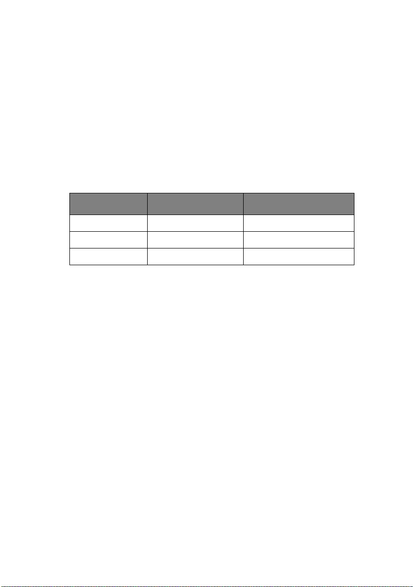
> Range:
m selects the available area in RAM. Only available area is
m = 0 or 128.
n1 = 00 – 127, Starting character location
n2 = n1 – 127, Ending character location
Character width limits are shown as follows:
d0: leading space width
d1: character width
d2: trailing space width
MODE D1 (MAX) D0 + D1 + D2 (MAX)
UTILITY 15 18
LQ 37 42
PROPORTIONAL 37 42
> Out of range:
n1 = n2: One character loaded.
n1 > n2: Data up to n2 is dumped and this command is
ignored.
80H <= n1, n2: Ignored from ESC to n2.
> Additional details:
To define a character, a grid that is 24 dots high is used,
one dot for each wire. The width of the character matrix is
dependent upon the character set in use (i.e. LQ, Utility or
Proportional).
Dots in the same row may not print in adjacent columns.
There must be an empty dot position to the left and to the
right of each dot that prints. This is true for Utility, LQ, and
Proportional. (See illustrations for character print
positioning).
Each vertical column (which has a maximum of 24 dots) is
first divided into three groupings of 8 dots. Each group of
8 dots is represented by one byte.
Technical Reference Guide – Command descriptions > 98
 Loading...