

Page 1

User Guide
People to People Technology
MICROLINE
590/591Elite
IBM-/EPSON
Page 2

Note To Customers
Every effort has been made to ensure that the information in this document is complete,
accurate and up-to-date. Mention of software packages manufactured by other
companies does not necessarily constitute endorsement by Oki. We do not assume
responsibility for errors beyond our control, nor can Oki guarantee that changes in the
software and equipment made by other manufacturers and referred to in this book will
not affect the applicability of information in this book.
© Copyright 1994 by Oki.
Oki is a registered trademark of Oki Electric Industry Co. Ltd.
Microline is a registered trademark of Oki Electric Industry Co. Ltd.
Epson is a registered trademark of Seiko Epson Corp.
IBM, IBM PC, PC XT and PC AT are registered trademarks of International Business
Machines Corp.
®
SWISS
is a trademark of Bitstream, Inc.
i
Page 3

Introduction
Oki ML590/91 Elite printers are now equipped with the latest Epson printer control
language called ESC/P2. While supporting ESC/P commands as its subset, ESC/P2
also provides:
– Fonts which can be defined by point size and pitch in one command.
– Font scaling between 8 and 64 points (Courier, Roman and Swiss typefaces).
– Enhanced raster graphics mode.
Your Microline 590/591 Elite incorporates INTELLIGENT HEAD TECHNOLOGY,
Oki’s proprietary method for improving paper handling and print quality. It
automatically senses the thickness of the loaded paper and adjusts the head gap prior
to printing. Therefore with awkward media like envelopes, multi part forms etc., it can
compensate for changes in the thickness of paper. Auto head gap technology means
superior print quality, especially on multi-part forms. It is simple to use as no manual
adjustment is necessary when changing paper types.
Other features of the ML590/591 Elite include:
– Zero tear for better forms management.
– Elimination of the bail arm, for a clearer and more versatile paper path.
– Seven resident fonts (including draft).
– Optional colour ribbon kit.
– Optional bottom push tractor unit, with stand and metal tear bar.
– Optional roll paper stand (ML590 Elite only).
– Single and dual bin cut sheet feeder assemblies.
– Eight resident bar code fonts.
– Fast Letter Quality printing at 120 cps and Draft at 360 cps (at 12 CPI).
ii
Page 4

Contents
Selecting Drivers ....................................................................................... vi
Chapter 1: Setup ....................................................................................... 1–1
Preliminaries .......................................................................................... 1–2
Connecting to Your Computer...............................................................1–3
Installing the Ribbon Cartridge.............................................................. 1–4
Installing the Paper Guide...................................................................... 1–5
Self Adjust Function .............................................................................. 1–6
Loading Rear Feed Continuous–Form Paper......................................... 1–7
Loading Single Sheet Paper ................................................................... 1–9
Printable Area ........................................................................................ 1–10
Setting the Top Of Form (TOF).............................................................1–10
Paper Park .............................................................................................. 1–11
Printing on Continuous–Form Paper with the CSF Installed................. 1–12
Clearing Paper Jams............................................................................... 1–13
Running a Self Test................................................................................ 1–14
Optional Accessories ............................................................................. 1–15
Chapter 2: Operation................................................................................ 2–1
Using the Control Panel ......................................................................... 2–1
Basic Controls........................................................................................ 2–1
Switch Combinations ............................................................................. 2–2
Button Functions in Menu Select Mode .................................................2–3
Print Characteristics ............................................................................... 2–4
Using the Menu Select Mode................................................................. 2–7
Entering the Menu Select Mode ............................................................ 2–7
Menu Selections.....................................................................................2–9
Explanation of Menu Terms .................................................................. 2–14
Cleaning ................................................................................................. 2–19
Problem Solving..................................................................................... 2–20
Printer Specifications ............................................................................. 2–21
iii
Page 5

Chapter 3: Control Code Reference................................................... 3–1
Print Quality........................................................................................... 3–1
Select Typeface...................................................................................... 3–2
Italics...................................................................................................... 3–3
Outline and Shadow............................................................................... 3–3
Character Pitch....................................................................................... 3–3
Pitch ....................................................................................................... 3–4
Proportional Spacing.............................................................................. 3–4
Double Width......................................................................................... 3–5
Compressed Printing.............................................................................. 3–5
Double Height........................................................................................ 3–6
Colour Printing....................................................................................... 3–8
Underlining ............................................................................................ 3–8
Overscore ............................................................................................... 3–9
Sub-/Superscript..................................................................................... 3–9
Bar Code Selection ................................................................................ 3–10
Combined Commands............................................................................ 3–11
Select Font ............................................................................................. 3–13
National Characters................................................................................ 3–16
All Character Set.................................................................................... 3–21
Code Page .............................................................................................. 3–22
Set Left and Right Margins.................................................................... 3–24
Justification............................................................................................ 3–25
Horizontal Tabs...................................................................................... 3–26
Vertical Tabs.......................................................................................... 3–27
Horizontal Dot Position ......................................................................... 3–30
Space Backwards ................................................................................... 3–30
Line Feed ............................................................................................... 3–32
Line Spacing .......................................................................................... 3–34
Form Feed/Form Length........................................................................ 3–35
Top of Form ........................................................................................... 3–36
Carriage Return...................................................................................... 3–37
Backspace .............................................................................................. 3–37
Reset....................................................................................................... 3–37
Clear Buffer ........................................................................................... 3–38
iv
Page 6

Delete One Character............................................................................. 3–38
Automatic Line Feed.............................................................................. 3–38
Unidirectional Printing........................................................................... 3–39
Printing Speed........................................................................................ 3–39
Print Suppress Mode.............................................................................. 3–40
Paper Out Sensor.................................................................................... 3–40
Emulation Mode..................................................................................... 3–40
Insert Page.............................................................................................. 3–41
Eject Page............................................................................................... 3–41
Cut Sheet Feeder Control....................................................................... 3–41
Chapter 4: ESC/P2 Command Summary............................................... 4–1
All Character Mode................................................................................ 4–1
Set Unit .................................................................................................. 4–1
Set Page Length ..................................................................................... 4–1
Set Page Format ..................................................................................... 4–2
Relative Vertical Print Position ............................................................. 4–2
Absolute Vertical Print Position ............................................................ 4–3
Set Font By Pitch And Point.................................................................. 4–3
Set Font Of Pitch And Point .................................................................. 4–4
Set Horizontal Motion Index (HMI) ...................................................... 4–4
Set Character Table................................................................................ 4–5
Set Raster Graphics Mode ..................................................................... 4–5
Print Raster Graphics ............................................................................. 4–6
Appendix A: Control Code Tables .......................................................... A–1
Appendix B: Character Code Tables ...................................................... B–1
IBM Character Sets................................................................................ B–1
Epson Character Sets ............................................................................. B–9
Appendix C: Interfacing........................................................................... C–1
Parallel Interfacing................................................................................. C–2
Serial Interfacing (RS-232C) ................................................................. C–5
Serial Interfacing (RS-422A)................................................................. C–7
Menu Selections for Serial Interfacing .................................................. C–10
Local Tests ............................................................................................. C–11
Communication Procedures ................................................................... C–12
v
Page 7

Selecting Drivers
Printer drivers are usually written for a particular model of printer and identified by the
name of that printer. Although most packages offer several selections, they cannot
have drivers for every printer. Therefore, you may have to choose a driver that was not
specifically written for the ML590/591 Elite but is compatible or nearly so. Installing
a driver is normally a simple process of making a selection from a menu. Look for one
of the following printers on your software’s printer driver selection. As you go further
down each list, you will have access to fewer ML590/591 Elite features.
The ML590/591 Elite is the successor to the ML390/391 but with added features. It is
therefore possible to use the ML390/391 printer driver in place of the ML590/591 Elite
driver.
IBM EPSON
EMULATION EMULATION
Oki ML590/591 Oki ML590/591
ML390/391 ML390/391
IBM PPR (XL24E) Epson (LQ-850, LQ-1050, LQ-870 and
LQ-1170)
IBM AGM
vi
Page 8

IMPORTANT
The wires in this mains lead are coloured in accordance with the following code:
GREEN AND YELLOW EARTH
BLUE NEUTRAL
BROWN LIVE
As the colours of the wires in the mains lead of this apparatus may not correspond with
the coloured markings identifying the terminals in your plug—PROCEED AS
FOLLOWS:
The wire coloured GREEN AND YELLOW must be connected to the terminal in the
plug marked with the letter E or by the safety earth symbol or coloured GREEN or
GREEN AND YELLOW. The wire coloured BROWN must be connected to the
terminal marked with the letter L or coloured RED. The wire coloured BLUE must be
connected to the terminal marked with the letter N or coloured BLACK or BLUE.
Ensure that the mains socket outlet is situated near your printer, for easy access.
WARNING: THIS APPARATUS MUST BE EARTHED
Ensure that your equipment is connected correctly. If you are in any doubt consult a
qualified electrician.
vii
Page 9

Setup
Choose a sturdy table, desk or printer stand to place your printer on when you remove
it from the carton box. Remove the styrofoam sides – be sure to save all packing
materials in case you need to ship the printer again – and check the box for these
contents:
● Oki Microline 590/591 Elite printer
● Paper guide
● AC mains cable
● Platen knob (fitted)
● Ribbon cartridge
● Printer handbook
Paper guide
☞
Printer
Platen knob
SEL
SEL
MENU
LF
SHIFT
FF/LOAD
MICRO FEED
TEAR
DOWN
PRINT QUALITY
MICRO FEED
PARK
DOWN
TOP
TOF
CHARACTER PITCH
TOF
AC Mains cable
Ribbon
Note: If any of these items is missing or damaged, see your dealer for a
replacement.
Interface cable and paper are sold separately.
If paper guide is not found in the accessories pack, it may already
be installed in the printer.
1 – 1
Page 10

Preliminaries
Open the access cover and remove the shipping retainer. (Save the shipping retainer
with the packaging materials, in case you need to ship the printer).
Shipping retainer
PRINT QUALITY
CHARACTER PITCH
QUIET
TOF
TOF
PARK
TEAR
PRINT
FF/LOAD
MICRO FEED
LF
DOWN
SET
MICRO FEED
DOWN
ITEM
SEL
SHIFT
GROUP
SEL
MENU
ALARM
POWER
The platen knob should already be installed, however, if this is not the case , or it has
been removed for any reason, the flat side of the shaft should be lined up with the flat
side of the knob (see diagram).
Platen knob
1 – 2
Page 11

☞
Connecting to Your Computer
Before you can use your printer, you need to attach it to your computer using an
interface cable.
Notes: Interface cables are not supplied with the printer.
Do not connect serial and parallel cables at the same time.
☞
AC mains cable
1. Make sure both your computer and your printer are switched OFF.
2. Attach the AC mains cable to the socket in the rear of the printer, and plug it into
an earthed power source.
Note: Do not use an unearthed adapter with your printer. The printer must
be connected to an earthed power supply.
3. Plug the printer end of your interface cable into the connector at the rear of the
printer.
4. Connect the other end of your interface cable to the printer port on your computer.
Interface cable
1 – 3
Page 12

Installing the Ribbon Cartridge
IMPORTANT
You have just bought the best printer, so be sure to use the only ribbons recommended
for it. Original Oki ribbons are the only ones recommended. Ask for them by name.
Please remember that if you buy any other ribbon your warranty may be invalidated.
Purchasing inferior ribbons really does not make sense. They do not last as long. They
are prone to shredding, which can cause damage to your printhead. That is why any
short term savings on cheaper ribbons are quickly lost.
So do not waste your time and money. Insist on Oki consumables for your Oki printer.
You can order them from your printer supplier.
1. Unpack the ribbon cartridge.
☞
2. Open the printer access cover.
3. Centre the printhead.
Centre the print head
PRINT QUALITY
CHARACTER PITCH
QUIET
TOF
TOF
PARK
TEAR
PRINT
FF/LOAD
MICRO FEED
LF
DOWN
SET
MICRO FEED
DOWN
ITEM
SEL
SHIFT
GROUP
SEL
MENU
ALARM
POWER
Note: The printhead can get very hot during extended periods of printing—
be sure to let it cool off before you touch it.
4. Place the ribbon into the printer, push down so that the cartridge snaps into
position.
5. Turn the blue take-up knob clockwise to take up any ribbon slack.
1 – 4
Page 13

Installing the Paper Guide
SEL
SEL
MENU
LF
SHIFT
FF/LOAD
MICRO FEED
TEAR
DOWN
MICRO FEED
DOWN
PRINT QUALITY
PARK
TOP
TOF
CHARACTER PITCH
TOF
Paper guide
Locate lugs into
grooves in paper
guide, and lift
Paper guide
1 – 5
Page 14

☞
Self Adjust Function
The self adjust function maintains the correct head gap setting and improved print
quality.
When the printer is powered up without paper, the printer starts the self adjust cycle
automatically after initialisation.
Use this function regularly when rear or bottom paper feed is used, and approximately
every one box or 2000 sheets.
Note: The printer ribbon must be installed before the self adjust function
is performed.
• Switch on the printer, the Power/ALARM lamp comes on and the printhead
assembly moves to its home position.
☞
• The Print Quality/Character Pitch lamp comes on.
• The Self Adjust cycle starts.
Note: Before replacing your printers ribbon deselect the printer, this will
centre the printhead (approximately two seconds) and maximise the head
gap (position 9). Once this has been done the old ribbon can be removed
and the new ribbon installed.
1 – 6
Page 15

Loading Rear Feed Continuous-Form Paper
When printing on rear feed continuous form paper use the built-in tractor.
1. Lift the rear paper guide
into the upright position.
2. Move the centre paper supports, on the tractor unit, to the middle of the paper.
Paper lever
Tractor unit
Paper support
3. Move the left hand tractor to the required position. (Pull the lever forwards to
unlock the tractor and slide to adjust. Push the lever back to lock.)
Paper guide removed
for clarity
1 – 7
Page 16

4. Open the tractor covers and set the first two sprocket holes on the paper on the
tractor pins.
Continuous
paper
Tractor cover
Lever
5. Adjust the right hand tractor to the width of the paper.
6. Close the tractor covers.
7. Lower the paper guide back into its horizontal position.
8. Pull the paper lever forwards (to the REAR paper symbol).
9. Press the FF/LOAD button to advance the paper to the front of the printer.
10. Set the Top Of Form, refer to Setting the TOF described in this chapter, to your
requirements and you are ready to print.
1 – 8
Page 17

Loading Single Sheet Paper
(No paper handling options installed)
PRINT QUALITY
SEL
SEL
MENU
EXIT
POWER
SHIFT
ALARM
LF FF/LOAD
Micro Feed
Down
Micro Feed
Up
GROUP ITEM
TEAR PARK QUIET
SET
PRINT
MENU
TOF
LQ
UTILITY
CHARACTER PITCH
10
RESET
17
COURIER
PRESTIGE
12
20
ROMAN
SWISS
GOTHIC
BOLD
15
PROP
1. If you have continuous-form paper in the printer, use the paper PARK feature to
back it out of the printer. Press the PARK button. The paper will retract from the
front of the printer.
2. Move the paper lever back to the single sheet setting (towards the back of the
printer – middle setting).
3. Raise the paper guide to its upright position.
Paper guides
Paper
4. Place a sheet of paper on the support and adjust the guides for the width of the
paper you are using. Start with the reference mark for the left edge. The paper will
then load automatically .
5. Adjust the TOF if necessary. Refer to Setting the TOF described later in this
chapter.
SEL
SEL
MENU
LF
SHIFT
FF/LOAD
MICRO FEED
TEAR
DOWN
PRINT QUALITY
MICRO FEED
PARK
DOWN
TOP
TOF
CHARACTER PITCH
TOF
1 – 9
Page 18

Printable Ar e a
The default top margin when using single sheets is 0.35 inch (8.89mm). However, the
1
top of form position can be adjusted by micro feed in steps of
position of 0.02 inches (0.5mm) from the top edge of the paper.
¦180 inches to a minimum
0.02 inch
minimum
(0.5mm)
0.02 inch
minimum
(0.5mm)
▼
▲
▼
▲
▲
0.16
inch
(4.1mm)
Additional Area
Additional Area
▲
▲
0.12
inch
(3.0mm)
▲
0.35 inch top
margin default
▼
(8.89mm)
Printable area
▲
0.5 inch bottom
margin default
▼
(12.7mm)
▲
The bottom margin defaults to 0.5 inches (12.7mm) with Bottom Margin Valid set in
the menu. If this menu item is set to Invalid, the bottom margin will be controlled by
the Page Length setting, and will allow printing to a minimum distance of 0.02 inches
(0.5mm) from the bottom edge of the page.
Note: Care should be exercised to ensure that the correct page length
☞
1 – 10
setting is selected when the Bottom Margin Invalid option is chosen, as
overprinting on to the platen roller could occur, damaging both the
printhead and the roller.
Page 19

Paper Park
Switching between continuous-form paper and single sheet paper is particularly easy
with your printer. Its automatic parking feature allows you to back continuous-form
paper out of the paper path at the touch of a button, and at the touch of another button
automatically positions a single sheet. The paper park feature still works when you
have an optional CSF installed on your printer whilst using continuous-form paper.
Continuous-form to Single Sheets
1. Press the PARK button. The continuous-form paper will retract from the paper
path.
2. Move the paper lever back (to the single sheet setting).
3. Press the FF/LOAD button to advance a sheet into the printer.
Single Sheet to Continuous-form
1. If there is a sheet in the printer, press the FF button to eject it.
2. Pull the paper lever forward (to the continuous-form setting).
3. Press the FF/LOAD button to advance the continuous-form paper to the front of
the printer.
1 – 11
Page 20

Setting the TOF
This establishes the position of the first print line on each page. The red line and M
character on the ribbon shield show the baseline of the current position and help place
the TOF where it is needed. To activate TOF press SHIFT and TOF together when the
SEL lamp is out.
If you are using a word processor that sets its own top margin, set the TOF for the
topmost line on the page. Otherwise we recommend positioning the top of the page in
line with the top of the plastic ribbon protector, attached to the printhead mechanism;
the first line of printing will then be about one inch from the top of the page.
1. Press the FF/LOAD button to advance the paper into the printer.
2. Press the SEL button so that the lamp goes out.
3. Continuous-form paper/Single Sheet paper: Hold down the SHIFT button and
use the MICRO FEED buttons corresponding to the direction you wish to move
the page. When the paper is in the correct position release both buttons.
4. Press the SEL button to re-select the printer.
When using the MICRO FEED buttons paper is moved in increments of
allowing accurate positioning of the TOF.
1
¦180 inch
1 – 12
Page 21

Clearing Paper Jams
In the unlikely event that you experience paper jams while using either continuousform paper or single sheets, the following guidelines explain in detail the correct
procedure for the removal and resetting of the jammed paper.
1. Turn the printer OFF.
2. Open the access cover.
3. Tear the paper off at the position of the push/pull tractor if you are using
continuous form paper.
4. If paper is jammed at the ribbon protector, move the printhead assembly away
from the jam carefully (ensure that there is no paper between the ribbon protector
and the platen) and turn the platen knob to feed the remaining paper out of the front
of the printer. If the paper jam occurs before the ribbon protector, turn the platen
knob so that the paper retracts along its loading path.
5. Clear the paper path and ensure that there are no scraps of paper left in the paper’s
loading path or the printer.
6. The printer is now ready for use.
1 – 13
Page 22

☞
Running a Self Test
After you have installed the ribbon and loaded paper, you are ready to run either of the
two self tests. These tests allow you to check that your printer is functioning properly.
Holding down the QUIET/TOF button while switching the printer ON produces a
continuous sample of the default print style.
Note: This sample prints along the entire length of the platen, so be sure
to use wide paper when running this test.
ML591Elite IE E F/W 05.00 YR4084-3066-06
F/W 03.03
CG 03.01
Holding down the LF button while turning the printer ON produces a limited sample
of each available print style.
ML591Elite IE E F/W 05.00 YR4084-3066-06
CG 03.01
When complete (three pages), the printer stops and the SEL lamp comes on.
To terminate either of these two self-tests, press the SEL button. This will return the
printer to its ready state and the SEL lamp will be lit.
1 – 14
Page 23

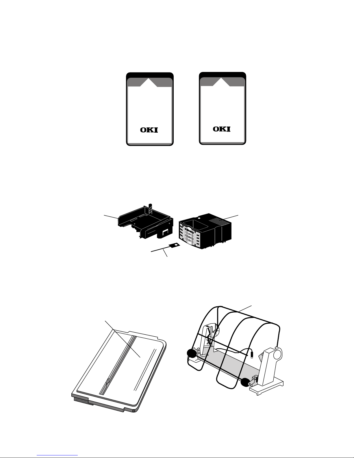
Optional Accessories
The following items are optional accessories for your printer.
Instructions for the installation of these items will be supplied with each accessory.
1. Cut Sheet Feeder
Cut Sheet Feeder
2. Pull Tractor and Cover
Available Types:
– Single bin 80 column
– Dual bin 80 column
– Single bin 136 column
– Dual bin 136 column
SEL
SEL
MENU
LF
SHIFT
FF/LOAD
MICRO FEED
TEAR
DOWN
PRINT QUALITY
MICRO FEED
PARK
DOWN
TOP
TOF
CHARACTER PITCH
TOF
Available Types:
– 80 column
– 136 column
3. Bottom Push Tractor Unit, Printer Stand and Tear Bar
Available Types:
– 80 column
– 136 column
Tear Bar
Printer Stand
1 – 15
Page 24
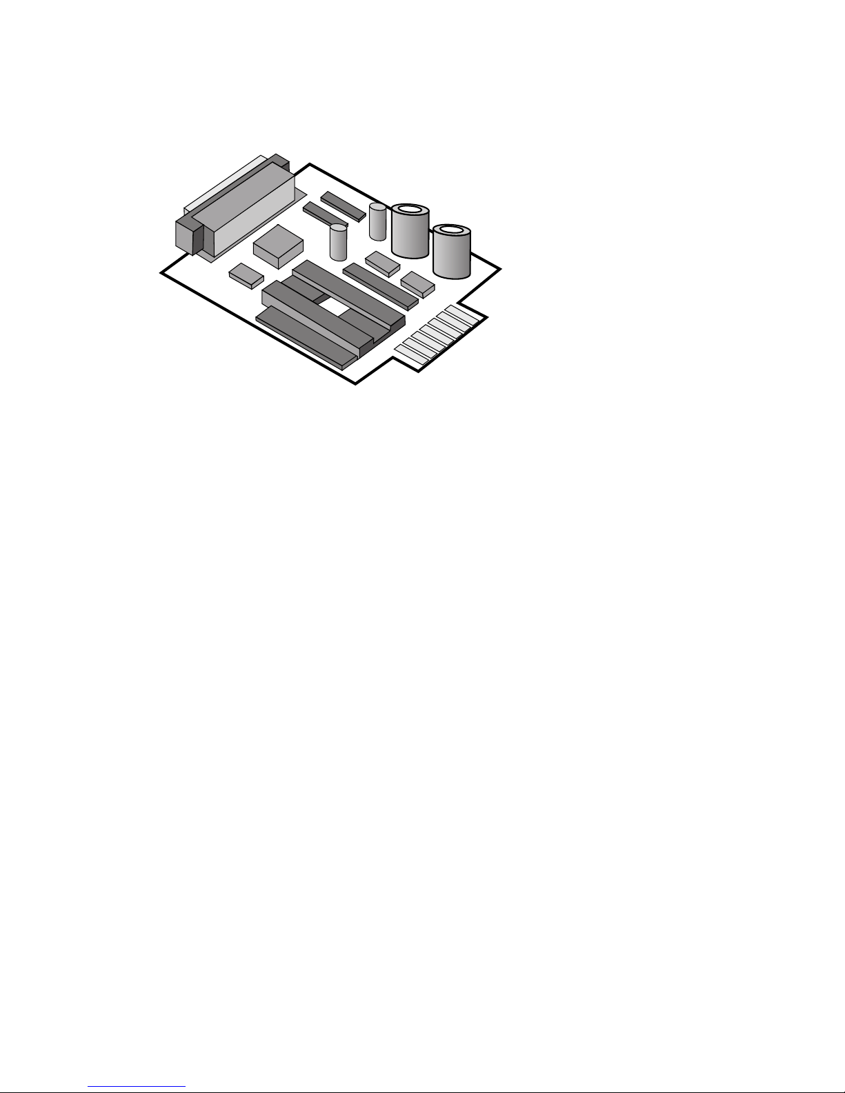
4. Font Card/RAM Card
y
y
Available Types:
INSERT
THIS SIDE UP
– East Europe All
– ECMA-94/Roman 8
ML590/591
– Greek
– OCR All
– Hebrew
FONT CARD
People to People Technolog
Made in Japan
5. Colour Printer Ribbon Kit
Ribbon lifting
mechanism
INSERT
THIS SIDE UP
ML590/591
RAM CARD
People to People Technolog
Made in Japan
32Kb for
Receive Buffer
(total 96Kb.)
Colour printer ribbon
6. Roll Paper Stand
Mounting plate
Ribbon advance key
Roll paper stand
1 – 16
Page 25
☞
7. Serial Interface Board.
Available Types:
– RS-232C Serial Interface board and
Current Loop Serial Interface Board
combined
– RS-422A Serial Interface board
IMPORTANT
Parallel and serial interface cables should not be connected to your printer
simultaneously.
1 – 17
Page 26

Operation
Using the Control Panel
The control panel puts many of your printer’s functions within reach of your fingertips.
It even lets you customise your printer for special applications without programming.
Experiment with these controls and you will see how much your printer can do and how
easy it is to use. The next few pages explain the basics of using the control panel.
SEL
SEL
MENU
EXIT
POWER
SHIFT
ALARM
LF FF/LOAD
Micro Feed
Down
GROUP ITEM
Micro Feed
Up
TEAR PARK QUIET
SET
MENU
PRINT
TOF
PRINT QUALITY
CHARACTER PITCH
RESET
LQ
UTILITY
10
17
COURIER
PRESTIGE
12
20
ROMAN
SWISS
GOTHIC
BOLD
15
PROP
Basic Controls
POWER light: Lit when On.
ALARM light: Lit to indicate alarm condition: paper out, paper jam, cover open.
LF button: Moves paper up one line (when printer is selected or deselected). If a CSF
is installed on the printer, pressing the LINE FEED button will cause a single sheet to
be inserted when there is no paper in the printer.
FF/LOAD button: Advances paper to the top of the next page (when printer is selected
or deselected). When bottom or rear feed is selected, the paper is loaded from the
tractor.
SHIFT and QUIET/TOF button: When the printer is deselected this button sets the
position of the Top Of Form. The TOF setting is not effective in single sheet mode.
SEL button: Selects or deselects the printer. When selected, the printer is ready to
receive data; when deselected, it will not print. Pressing this button during a self-test
will terminate the test and return the printer to its ready state.
SEL lamp: Lights when printer is selected (ready to receive data); goes out when it is
deselected. The light blinks when the printer is in Print Suppress mode (refer to the
Menu Settings for more details).
2 – 1
Page 27

PRINT QUALITY: Selects the quality and print style of the typeface.
CHARACTER PITCH: Selects the size of the printed characters.
PARK: Selects the park position for continuous paper, allowing single sheets to be fed
from the front of the printer.
TEAR: Advances the paper to the tear off position (serrated bar above acoustic cover),
allowing continuous paper to be torn off at random.
MICRO FEED: Advances the paper 1/180 inch in the direction of the arrows for fine
adjustment (up or down).
When pressing the MICRO FEED button (up or down) with the SHIFT button the
insert position for paper is set.
SHIFT button: Expands the facility of the buttons.
QUIET button: Selects the quiet printer mode.
Switch Combinations
The following buttons have special functions when held down during power up:
LF: Activates the print samples self-test.
LF and SEL: Resets the Menu to the factory settings.
QUIET/TOF: Activates the rolling ASCII print self-test.
SEL and FF/LOAD: Puts the printer into the Hex Dump Mode.
FF/LOAD and TEAR: Returns the printer to the default Menu (factory) settings.
This option also sets the insert position for paper to the factory setting.
PARK and QUIET/TOF: This option sets the insert position for paper to the factory
setting.
2 – 2
Page 28

Button Functions in Menu Select Mode
When the printer is in the MENU select mode, the features listed below the buttons are
activated.
MENU and SHIFT: Enters the MENU mode.
PRINT: Prints the current menu settings.
GROUP: Switches between the broad menu categories (FWD. direction).
SHIFT and GROUP: Switches between the broad menu categories (REV. direction).
ITEM: Displays the features contained in each of the categories (FWD. direction).
SHIFT and ITEM: Displays the features contained in each of the categories (REV.
direction).
SET: Selects and stores the options available for each feature in the menu (FWD.
direction).
SHIFT and SET: Selects and stores the options available for each feature in the menu
(REV. direction).
SHIFT and EXIT: Exits from the menu select mode and returns the printer to its ready
state. The buttons are returned to their basic functions.
SHIFT and PRINT: Prints the current menu group settings.
2 – 3
Page 29

Print Characteristics
The print quality and character pitch buttons let you control basic printing features
through your printer’s control panel:
1. Press the SEL button (SEL light goes out).
2. Press the features that you wish to change (light goes on).
3. Press the SEL button.
The panel always indicates the actual settings of the printer. If you change any of these
features through your software, the panel lights will also change to reflect this feature
choice.
The panel will only allow you to select valid combinations of features. For example,
proportional spacing can only be selected when the print quality choice is set to LQ.
The two printing features available on the control panel offer the following selection
of modes:
Print Quality
There are seven resident fonts which can be selected on your printer. For an example
of each please refer to the self test print out.
COURIER
ROMAN
GOTHIC
SWISS BOLD
SWISS
PRESTIGE
UTILITY
2 – 4
Page 30

COURIER The COURIER mode produces crisp, clean characters,
similar to a typewriter. Print in COURIER when you
want your correspondence and reports to look especially
polished. You can use COURIER mode to print 10, 12,
15, 17.1 and 20 Characters Per Inch (CPI), as well as
proportional spacing.
ROMAN The ROMAN mode also produces crisp, clean serif
characters in the same way as COURIER. You can use
ROMAN mode to print 10, 12, 15, 17.1 and 20 Characters
Per Inch (CPI), as well as proportional spacing.
GOTHIC The GOTHIC mode also produces crisp, clean sans serif
characters in the same way as COURIER. You can use
GOTHIC mode to print 10, 12, 15, 17.1 and 20 Characters
Per Inch (CPI), as well as proportional spacing.
SWISS BOLD The SWISS BOLD mode also produces crisp, clean
characters in the same way as SWISS, however the
characters are emphasised. You can use SWISS BOLD
mode to print 10, 12, 15, 17.1 and 20 Characters Per Inch
(CPI), as well as proportional spacing.
SWISS The SWISS mode also produces crisp, clean sans serif
characters in the same way as COURIER. You can use
SWISS mode to print 10, 12, 15, 17.1 and 20 Characters
Per Inch (CPI), as well as proportional spacing.
PRESTIGE The PRESTIGE mode also produces crisp, clean serif
characters in the same way as COURIER. You can use
PRESTIGE mode to print 10, 12, 15, 17.1 and 20
Characters Per Inch (CPI), as well as proportional spacing.
2 – 5
Page 31

Serif typefaces: COURIER, ROMAN, GOTHIC
San Serif typefaces: SWISS, SWISS BOLD and PRESTIGE typefaces can
produce clean, crisp letter quality (LQ) characters. Use
these typefaces for professional looking correspondence
and reports.
UTILITY The Utility mode is ideal for high-volume printing. It is
much faster than LQ, but the printed output is not as
dense as the higher-quality modes. Utility mode supports
all the character pitches.
Character Pitch (width selections)
10, 12, 15, 17.1 and 20 pitch and proportional spacing are available for use with
resident COURIER, GOTHIC, ROMAN, BOLD, SWISS, PRESTIGE and UTILITY
(as proportional).
☞
Note: Pitches available with downloaded fonts are font dependent.
2 – 6
Page 32

Using the Menu Select Mode
The Menu Select mode gives you fingertip control over some of your printer’s most
important features. Menu selections are chosen while in the Menu Select mode and
retained in the printer’s non-volatile memory. In effect your settings become the
default settings, although they can be changed through software commands, through
the control panel or through resetting the menu.
☞
Note: You can override features set on the menu using either the control
panel or commands sent from your computer. However, when you turn off
the printer, features set by those methods will be cancelled. Features set on
the menu will stay in effect, even when the printer is unplugged.
Entering the Menu Select Mode
To enter MENU mode, depress SEL/MENU and SHIFT buttons or depress SEL/
MENU during power up.
Upon entering Menu mode, press the GROUP button to print a group of menu items,
ITEM button to print a single line menu item or the SET button to assign a different
value.
See Key functions for description of operation within the Menu mode.
To exit MENU mode, press the SEL/MENU button together with the SHIFT button.
If conflicting features/functions are set in Menu mode, the printer will treat these
features/functions according to its priority table.
The TOF position is not affected by Menu mode if paper length is not changed. If paper
length changes, set the Menu end position at TOF.
Depressing SEL/MENU + LF or FF/LOAD + TEAR buttons while powering up will
reset the menu back to its factory defaults, (see Factory Settings for further details).
If the Operator Panel is set to Limited Operation, press the SEL/MENU button during
power up in order to enter MENU.
2 – 7
Page 33

☞
The MENU is printed bi-directionally in Utility mode.
Note: If in the middle of the Menu Select mode you should run out of paper,
the red alarm light on the control panel goes on and the printer goes off line.
Reload paper and continue by pressing the SEL button; the printer then
resumes its function in the Menu Select mode.
2 – 8
Page 34

Menu Selections
☞
NOTE: Factory default settings are printed in bold.
Group Item Selections
Printer Emulation EPSON LQ, IBM PPR/AGM
Control Mode
Font Print Mode LQ Courier, LQ Roman, LQ
Swiss, LQ Swiss Bold, LQ Gothic,
LQ Prestige, Utility, Font Card
Pitch 10CPI, 12CPI, 15CPI, 17.1CPI,
20CPI
Proportional No, Yes
Spacing
Style Normal, Italics
Size Single, Double
Symbol Character Set Set II, Set I
Sets
Language Set ASCII, French, German, British,
Danish I, Swedish I, Italian,
Spanish I, Japanese, Norwegian,
Danish II, Spanish II, Latin
American, French Canadian,
Dutch, Swedish II,
Swedish III, Swedish IV, Turkish,
Swiss I, Swiss II, Publisher
Zero Character Unslashed, Slashed
Code Page USA, Canada-French,
Multilingual,
Portugal, Norway,
Turkey
Slashed letter O NO, YES
2 – 9
Page 35

Group Item Selections
Rear Feed Line Spacing 6LPI, 8 LPI
Form Tear off Off, 500ms, 1 sec, 2 sec
Skip Over Perforation No, Yes
Page Width (591E only) 13.6", 8"
Page Length 11", 11 2/3", 12", 14", 17", 3",
3.5", 4", 5.5", 6", 7", 8", 8.5"
Gap Control Auto Gap, Semi Auto Gap, 1,
2, 3, 4, 5, 6, 7, 8, 9
Bottom Feed Line Spacing 6LPI, 8 LPI
Form Tear Off Off, 500ms, 1 sec, 2 sec
Skip Over Perforation No, Yes
Page Width (591E only) 13.6", 8"
Page Length 11", 11 2/3", 12" 14", 17", 3",
3.5", 4", 5.5", 6", 7", 8", 8.5"
Gap Control Auto Gap, Semi Auto Gap, 1,
2, 3, 4, 5, 6, 7, 8, 9
Top Feed Line Spacing 6LPI, 8 LPI
Form Tear Off Off, 500ms, 1 sec, 2 sec
Bottom Margin Valid, Invalid
Page Width (591 E only) 13.6", 8"
Page Length 11", 11 2/3", 12", 14", 16.57",
3", 3.5", 4", 5.5", 6", 7", 8", 8.5"
Gap Control Auto Gap, Semi Auto Gap, 1,
2, 3, 4, 5, 6, 7, 8, 9
Wait Time 500ms, 1 sec, 2 sec
Page Length Control Menu Setting, Actual Page
Length
2 – 10
Page 36

Group Item Selections
Set-Up Graphics Uni-directional, Bi-directional
Receive Buffer Size 64k, 1 Line, 32k, 96k (with
option)
Paper Out No, Yes
Override
Print Registration 0, 0.05, 0.1, 0.15, 0.2, 0.25mm
left
0.25, 0.2, 0.15, 0.1, 0.05mm
right
Operator Panel Full Operation,
Function Limited Operation
Reset Inhibit No, Yes
Print Suppress Yes, No
Effective
Auto LF No, Yes
Auto CR No, Yes
(IBM PPR mode)
CSF Bin Select Bin 1, Bin 2
(when dual bin CSF
installed)
SI Select Pitch 17.1 CPI, 15 CPI
(10 CPI)
(IBM PPR/AGM
mode)
SI Select Pitch 20 CPI, 12 CPI
(12 CPI)
(IBM PPR/AGM
mode)
Time Out Print Valid, Invalid
Auto Select No, Yes
2 – 11
Page 37

Group Item Selections
Ribbon Selection Black Ribbon, Black, Yellow,
Magenta, Cyan, Violet, Orange,
Green
Printhead Gap 0, +1, -1
Adjust
Graphics Speed Low, High
Centering Position DEFAULT, MODE1,
MODE2 (591 only)
Parallel I/F I-Prime Buffer Print, Buffer Clear,
Invalid
Pin 18 +5V, Open
AutoFeed XT Invalid, Valid
(EPSON only)
Serial I/F Parity None, Odd, Even
(when
installed)
Serial Data 8 Bits, 7 Bits
7- or 8- Bits
Protocol Ready/Busy, XON/XOFF
Diagnostic Test No, Yes
Busy Line SSD-, SSD+, DTR, RTS
Baud Rate 9600 BPS, 4800 BPS, 2400 BPS,
1200 BPS, 600 BPS, 300 BPS,
19200 BPS
DSR Signal Valid, Invalid
DTR Signal Ready on Power Up,
Ready on Select
Busy Time 200 ms. 1 sec
CSF Bin 1 Line Spacing 6 LPI, 8 LPI
(when CSF
option is
installed)
2 – 12
Page 38

Group Item Selections
Bottom Margin Valid, Invalid
Page Width (591 E only) 13.6", 8"
Page Length 11", 112/3", 12", 14", 16.57",
3", 3.5", 4", 5.5", 6", 7", 8", 8.5"
Gap Control Auto Gap, Semi Auto Gap, 1,
2, 3, 4, 5, 6, 7, 8, 9
CSF Bin 2 Line Spacing 6 LPI, 8 LPI
(when dual
bin CSF
option is
installed)
Bottom Margin Valid, Invalid
Page Width 13.6", 8"
Page Length 11", 112/3", 12", 14", 16.57",
3", 3.5", 4", 5.5", 6", 7", 8", 8.5"
Gap Control Auto Gap, Semi Auto Gap, 1,
2, 3, 4, 5, 6, 7, 8, 9
2 – 13
Page 39

Explanation of menu items
Emulation Mode: Select the printer command set you want your printer to use.
Choose Epson LQ series or IBM PPR or AGM.
Print Mode: Choose LQ for Letter Quality printing, Utility for quicker printing.
Pitch: Choose character width measured in characters per inch (CPI), or proportionally
spaced characters.
Style: Choose Normal (upright) or Italics (slanted).
Size: Choose Single or Double width and height.
Character Set: Choose IBM Character Set 1 or Set 2 as the default character set.
Language Set: These sets replace certain symbols with special characters used in the
respective foreign languages (see National Character Sets in Appendix B).
Zero Character: Choose Slashed when it is important to distinguish between a zero
(0) and a capital letter O.
Code Page: This option is available in both IBM and EPSON emulation. This allows
several character sets containing special characters to be accessed using the format
which selects IBM Character Sets 1 and 2 and the All Character Set.
Slashed letter O: Character ¢ (155) and ¥ (157) will be set to ø and Ø if set to YES.
Line Spacing: Choose 6 lines per inch (1/6 inch line spacing) or 8 LPI (1/8 inch
line spacing).
Form Tear Off: Use this option to turn the forms tear off feature ON or OFF or to allow
a wait time after a form feed occurs. When it is set to off, if the printer receives a FF
or end of page is reached and there is no more data, the paper is fed to the TOF position
and the printer is deselected. After the sheet has been removed the user should push the
SEL switch to resume or start a print job. The default setting is OFF.
2 – 14
Page 40

Bottom Margin: If this item is set to VALID, printing will not occur within the bottom
0.5 inch of the paper.
Skip Over Perforation: Choose YES if you want the printer to advance automatically
to the next page when it comes within one inch of the bottom of the page. If your
software has its own page formatting controls, set this item to NO to avoid interference.
Page Width: Choose the width of paper that you are printing on.
Page Length (Inches): Choose the length of the continuous form paper you are using.
This enables the printer to keep track of the initial printing position on each page
(TOF).
Paper Out Override: The paper out detector senses when less than one inch of paper
remains in the printer and stops printing at that point. Choosing YES overrides the
detector so you can print closer to the bottom of the page if you are using single sheets.
Be careful if you use this feature: it lets the printer continue printing when there is no
more paper, which causes loss of data and may damage the printhead and the platen.
The default setting is NO.
Graphics: Choose unidirectional (left to right only) for better graphics print registration
at slower speed. Choose bidirectional for higher print speed.
Receive Buffer Size: Choose the size of the buffer (64K, 32K, 1 Line or 96K with
optional RAM card installed). This allows you to send large jobs to your printer, which
can be held in a larger buffer, and reduce the time that your computer is busy sending
data.
If your computer has problems with device time-outs due to the time taken to clear the
buffer, select a smaller buffer size. The time taken to clear the buffer will be shorter
and the computer will be able to resume transmitting data.
Printhead Gap Control: If this item is set to Auto Gap, every time new paper is loaded
the printhead gap is automatically adjusted. If it is set to Semi Auto Gap, the printhead
gap is automatically adjusted every time the paper source is changed.
If constant thickness paper is used the following gap adjustments can be set for better
throughput.
2 – 15
Page 41

Setting Multi paper Interleaf Max. paper Envelope
Thickness
1-- - 2 1P 1P 0.10 3 2P 2P 0.16 4 3P - 0.20 5 4P 3P 0.265 6 5P 4P 0.33 o
7 6P 5P 0.40 o
8 6P 5P 0.40 o
9-- - o
Wait Time: Is the amount of time delay before the paper is automatically fed, using
the top feed.
Page Length Control: The printer can detect the page length by paper-end sensors if
the Actual Page Length is chosen. Otherwise, the default value is set in the menu.
Print Registration: Use this option with bidirectional bit image graphics to improve
registration. Although 0 is generally the best selection, choosing another value may
compensate for registration problems with some graphics software packages.
Operator Panel Functions: Full Operation is the normal setting. Choose Limited
Operation to deactivate the PRINT QUALITY and CHARACTER PITCH buttons on
the control panel. Then you can control these features only through your software. This
can be useful when several people are using the printer and you do not want its settings
changed.
Reset Inhibit: Choose YES if your software package or computer sends an initialization
command at the start of each job. This initialization command will reset any features
that you may have set to the menu default.
Print Suppress Effective: Select YES when you want the print suppress commands
in each of the emulations to be active. The print suppress commands are ignored when
this option is set to NO.
2 – 16
Page 42

Auto LF: Choose YES to have the printer automatically add a Line Feed command
to each Carriage Return command it receives. The choice depends on whether your
computer adds a Line Feed. If your printout is consistently double spaced, select NO;
if it overprints, choose YES.
Auto CR (IBM): Choose NO to prevent the printer from automatically adding a
Carriage Return to each Line Feed command it receives. This feature only appears in
IBM emulation.
CSF Bin Select: Select Bin 1 or Bin 2 for paper feed option.
SI Select (10 CPI): Selects 17.1 or 15 CPI, in IBM emulation only.
SI Select (12 CPI): Selects 20 or 12 CPI, in IBM emulation only.
Time Out Print: When validated, if the printer does not receive print commands and
nothing is received for 150msec, the buffer characters are printed. If invalidated, the
buffer is not printed until print commands are received.
Auto Select: If selected, after paper is automatically loaded using the FF/LOAD
button, the printer is set to ON-LINE. If NO is selected, the printer does not
automatically come ON-LINE after paper has been loaded.
Ribbon Selection: (Optional Colour Version only). If you are using a colour ribbon,
select the standard printing colour – normally Black. If you are using a black ribbon,
use the BLACK RIBBON selection for longer life.
Printhead Gap Adjust: If print quality is still light after installing a new ribbon, this
item should be set to -1. If paper jams occur, this item should be set to +1. Normally
this is set to 0.
Graphics Speed: Choose HIGH to make low density graphics printing faster.
Centering Position: This feature allows the user to obtain optimum quality and
performance when using smaller paper sizes. It does this by limiting the distance the
printhead has to travel. There are three settings, DEFAULT, MODE1 and MODE2
(591 only).
2 – 17
Page 43

The following options are used when the parallel interface is selected.
I-Prime: Buffer print—when this signal is received, the printer is initialised after the
buffer data is printed. Buffer clear—the printer is initialised after the current line has
been printed. Invalid—This signal is ignored.
Pin 18: This pin supplies 5V or open circuit as required by external device when
connected to interface.
Auto Feed XT(Epson emulation only): There is normally no Line Feed after a
Carriage Return if the Auto Line Feed is set to NO. However, in the Epson emulation,
if the Auto Line Feed is set to NO and the Auto Feed XT is set to valid, a Line Feed
is executed upon an Auto Feed signal on pin 14 of the parallel interface. This exception
may be necessary for some hardware/software combinations.
The following options are used only if the serial interface is selected (see Appendix
C for details).
Parity: Selects parity.
Serial Data 7- or 8- Bits: Selects data format. When the Serial Data 7- or 8- Bits is
set to 7, the Parity must be set to either ODD or EVEN. 7- Bit Serial Data will not be
printed correctly if the Parity is set to NONE.
Protocol: Selects interface protocol.
Diagnostic Test: Activates the printer’s interface diagnostic test.
Busy Line: Selects line used for busy signal.
Baud Rate: Selects data transmission speed.
2 – 18
Page 44

The following options are used when the parallel interface is selected.
Parity: Selects parity.
Serial Data 7- or 8- Bits: Selects data format. When the Serial Data 7- or 8- Bits is set
to 7, the Parity must be set to either ODD or EVEN. 7- Bit Serial Data will not be printed
correctly if the Parity is set to NONE.
Protocol: Selects interface protocol.
Diagnostic Test: Activates the printer’s interface diagnostic test.
Busy Line: Selects the line used for busy signal.
Baud Rate: Selects data transmission speed.
DSR Signal: Sets the Data Set Ready (DSR) signal status.
DTR Signal: Selects Data Terminal Ready (DTR) signal status.
Busy Time: Sets busy signal timing.
Cleaning
Every six months (or after 300 hours of operation), take a clean, dry soft cloth and dust
the area around the carriage shaft and platen. Be sure to remove any loose particles of
paper. Do not use solvents or strong detergents on the cabinet. Be sure to turn the printer
OFF before cleaning.
2 – 19
Page 45

Problem Solving
Why does nothing happen when I turn on the printer?
The printer may not be plugged in. Check the power cord connection to the printer and
the outlet.
Why is the ALARM light on?
Check to see if:
● Paper is out.
● The paper lever is not set for the type of paper that you are using (single sheet or
continuous-form paper).
● The paper or ribbon is jammed.
After correcting the alarm condition, you may have to turn the printer off and on again
to make the ALARM light go out.
Why is the MENU light flashing?
The printer suddenly changes to unidirectional printing, then stops completely and the
MENU lamp flashes.
This is a feature designed to protect the printhead. Heat can build up in the printhead
when it has been printing for a long period of time, so when the printhead reaches a
certain temperature, the printer switches to unidirectional printing. If heat continues to
increase, the printer will stop until the printhead cools down; then it resumes printing.
Why does the printer not print when data is sent from the computer?
You may have the printer deselected (the SELECT light is out). Press the SELECT
button. If the SELECT light still does not come on, even though the POWER light is
on, turn the printer OFF and check that the interface connection from the computer is
secure.
2 – 20
Page 46

Printer Specifications
Print Method Impact dot matrix
Printhead 24 pin
Print speed
Utility 360 CPS (characters per second) at 12 CPI
Letter quality 120 CPS at 12 CPI
Characters per line ML590 Elite ML591 Elite
at 10 CPI 80 136
at 12 CPI 96 163
at 15 CPI 120 204
at 17.1 CPI 137 233
at 20 CPI 160 272
Reliability
Mean time between failures 6000 hours at 25% duty cycle, 35% page density
Mean time to repair 15 minutes
Printhead life 200 million characters
Ribbon life 4 million characters (black ribbon)
Electrical characteristics
Voltage 230 VAC (+6%, -14%), 240 VAC (±10%)
Frequency 50/60 Hz at ± 2%
Interface Centronics parallel standard
RS-232C/RS-422A serial optional
Dimensions ML590 Elite ML591 Elite
Size Depth 380mm (14.96 inch) Depth 380mm (14.96 inch)
Width 431mm (16.97 inch) Width 585mm (23.03 inch)
Height133mm (5.24 inch) Height 133mm (5.24 inch)
Weight 6.5 kg 8.6 kg
Paper Specifications
Width 76.2 mm to 254.0 mm (3 inch to 10 inch) ML590
76.2 mm to 406.4 mm (3 inch to 16 inch) ML591
2 – 21
Page 47

Continuous forms
Single part forms
Weight 45 – 90g/m2 (12 to 24 lb.)
Thickness 0.051 mm to 0.124 mm (0.0020 inch to 0.0049 inch)
Multipart-carbon lined or
pressure sensitive
Weight 34 – 42g/m2 (9 to 11lb.)
Number of copies Original plus three copies
Thickness 0.36 mm max. (0.014 inch max.)
Multipart-interleaf
Weight Paper: 38 – 45g/m2 (10 to 12 lb.)
Carbon: 34g/m2 (9 lb.)
Number of copies Original plus three copies
Thickness 0.36 mm max. (0.014 inch max.)
0.44 mmMax. (o.017 inch) – bottom feed only.
Cut sheets
Single part
Weight 45 – 90g/m2 (12 to 24 lb.)
Thickness 0.051 mm to 0.124mm (0.002 inch to 0.0049 inch)
☞
☞
Envelopes (individual)
Weight 90g/m2 (24 lb.) max.
Thickness 0.406 mm (0.016 inch max.)
Dimensions 165 x 92 mm max. (6.5 inch x 3.625 inch)
225.4 mm x 98.4 mm (8.875 inch x 3.875 inch)
241.3 mm x 104.8 mm (9.5 inch x 4.125 inch)
Card stock
Weight 150g/m2 (40 lb.) max.
Thickness 0.20 mm (0.008 inch max.)
Dimensions 127 mm x 203 mm max. (5 inch x 8 inch max.)
Note: Use with bottom feed only.
Labels
Carrier 208.3 mm max. (8.20 inch max.) width
Thickness 0.28 mm max. (0.011 inch max.)
Note: Use bottom feed only. Do not use fabric labels. Do not print on the
edge or the perforation of the label.
2 – 22
Page 48

☞
Continuous Envelope
Weight 90g/m2 (24 lb.) max.
Thickness 0.36 mm max. (0.014 inch max.) – bottom feed only.
No overlapping.
Transparencies (OHPs)
Thickness 0.10 mm max. (0.004 inch max.)
Dimensions 210 mm (8.20 inch) wide x 297 mm (11 inch) long.
Note: Oki recommend 3M transparencies.
2 – 23
Page 49

Control Code Reference
This chapter describes the printing and formatting features and the codes that control
them. It is not just for programmers, if you want to modify your software to add a
particular function, or if you want to embed extra commands in a document, you will
find the necessary information here. Even if you just use the front panel to control your
printer, the explanations of the features and how they work will be helpful.
In this chapter we list each control code in decimal, hexadecimal and ASCII notation.
The control code table in Appendix A gives you a quick reference for each function
code. Because the printer can emulate four printers, there may be as many as four
different ways to control a particular function, depending on the emulation you have
selected from the menu. To make sure you know which one to use, we have marked
the commands with letters to indicate which emulation they apply to:
E = Epson LQ series (LQ 850/LQ 1050
E2 = Epson ESC/P2 series (LQ 870/LQ 1170 See Chapter 4)
P = IBM Proprinter X24E/XL24E
A = IBM Proprinter X24E/XL24E AGM (Alternate Graphics Mode)
In many cases, all emulations use the same commands. In almost all cases, both IBM
emulations use the same commands. Details on specific emulations fall under
appropriate headings. These separate sections only appear when there are differences
among the emulations.
Print Quality Decimal Hex ASCII Comp
Select LQ/Utility print 27 120 n 1B 78 n ESC x n E
quality
n = 1: Select LQ; n = 0: Select Utility
EPSON
Use utility printing for drafts and other documents that you want to print quickly. LQ
(Letter Quality) printing is slower than Utility, but the characters are crisper and more
like the characters produced by a typewriter. Use LQ for final drafts and important
documents where appearance matters. Your printer’s front panel or the Menu Select
mode can also select print quality.
IBM
You can use the ESC I command to specify LQ or utility printing.
3 – 1
Page 50

Print Quality Decimal Hex ASCII Comp
Begin emphasised printing 27 69 1B 45 ESC E E P A
End emphasised printing 27 70 1B 46 ESC F E P A
Begin enhanced printing 27 71 1B 47 ESC G E P A
End enhanced printing 27 72 1B 48 ESC H E P A
Your printer produces bold type by printing each dot of a character twice instead of
once. In emphasized printing, the pairs of dots are offset horizontally, enhanced
printing is produced with a vertical offset.
You can combine enhanced and emphasized printing for an especially bold effect. For
headlines, try using them in combination with double width characters. You can also
combine emphasized printing with double height characters.
Select Typeface Decimal Hex ASCII Comp
Select Typeface 27 107 n 1B 6B n ESC k n E P A
n = 0 Roman
1 Swiss
2 Courier
3 Prestige
5 OCR-B (if optional OCR-All font card is installed)
6 OCR-A (if optional OCR-All font card is installed)
122 Swiss Bold
124 Letter Gothic
126 Resident (Courier)
127 Option Card (if any option card is installed)
This command allows you to select a typeface. The resident Courier typeface is your
printer’s default. (A resident font is built into the printer, as opposed to those that are
available on optional font cards.) If you want to select OCR-A or OCR-B you must
have the appropriate font card installed. You can switch easily between resident and
font card typefaces by substituting the appropriate value for the variable in this escape
sequence. You can also use Menu Select mode or the FONT button on the printer’s
control panel to select resident or font card typefaces.
3 – 2
Page 51

Italics Decimal H e x ASCII Comp
Begin italics 27 52 1B 34 ESC 4 E
End italics 27 53 1B 35 ESC 5 E
Begin italics 27 37 71 1B 25 47 ESC % G P A
End italics 27 37 72 1B 25 48 ESC % H P A
Italic printing is slanted (e.g. OKI) and is used to lend emphasis to phrases, sentences
or entire paragraphs.
If you intend to print an entire document in italics, you may choose to select this
printing style in Menu Select mode.
Outline and Shadow Decimal H ex ASCII Comp
Begin outline 27 113 1 1B 71 01 ESC q SOH E P A
Begin shadow 27 113 2 1B 71 02 ESC q STX E P A
Begin shadow and outline 27 113 3 1B 71 03 ESC q ETX E P A
Cancel shadow and/or outline 27 113 0 1B 71 00 ESC q NUL E P A
☞
Use the outline and shadow effects to produce more interesting and stylish headings.
They can be combined together as well as with emphasised and /or enhanced printing
for an even more striking effect.
Note: Outline and shadow printing commands can only be used for
printing characters, they cannot be used to print line graphics.
Character Pitch Decimal Hex ASCII Comp
Begin 10 CPI (Pica) 27 80 1B 50 ESC P E
Begin 12 CPI (Elite) 27 77 1B 4D ESC M E
Begin 10 CPI (Pica) 18 12 DC2 P A
Begin 12 CPI (Elite) 27 58 1B 3A ESC : P A
Begin 15 CPI 27 103 1B 67 ESC g E P A
Character pitch, or width, is measured in Characters Per Inch (CPI). For example, at
1
10 CPI, each character is
/10 inch wide. The double width and compressed printing
commands interact with the basic pitches listed above to produce a range of character
widths. See the Character Width table below for all possible widths.
3 – 3
Page 52

Pitch can also be set in Menu select mode or on the printer’s control panel. In addition,
pitch is one of the features available through the print mode combination commands
in both emulations.
Pitch Double Width Compressed* (Epson only)
10 CPI 5 CPI 17.1 CPI
12 CPI 6 CPI 20 CPI
15 CPI 7.5 CPI Cannot be compressed
17.1 CPI 8.5 CPI Cannot be compressed
20 CPI 10 CPI Cannot be compressed
Proportional Proportional double Proportional condensed
* These compressed width values apply to the Epson emulation only. In IBM
emulations, the SI command produces 17.1 CPI and ESC SI produces 20 CPI
regardless of initial pitch.
Proportional Spacing Decimal Hex ASCII Comp
Proportional spacing 27 112 n 1B 70 n ESC p n E
n = 1: Begin proportional spacing; n = 0 End proportional spacing
Proportional spacing 27 80 n 1B 50 n ESC P n P A
n = 1: Begin proportional spacing; n = 0 End proportional spacing
Proportional spacing adjusts the space between letters to compensate for the varying
widths of individual characters. Unlike fixed spacing, where all characters are formed
within a matrix of uniform width at a specified pitch, proportional spacing gives more
horizontal space to wide characters, such as w or M, and less to narrow characters, such
as I or f. The printed result is more attractive and easier to read than fixed-space
printing.
Because the characters have different widths, proportionally spaced fonts have no
fixed pitch. Therefore, margin settings are only approximate unless your software
specifically supports proportional spacing. Proportional spacing is available only with
Letter Quality (LQ) printing. You can also select proportional spacing in Menu Select
mode or on the printer’s control panel. In addition, proportional spacing is one of the
features available through the print mode combination commands in all the emulations.
3 – 4
Page 53

Double Width Decimal Hex ASCII Comp
Double width printing 27 87 n 1B 57 n ESC W n E P A
or 28 69 n 1C 45 n FS E n E
n = 1: Begin double width printing; n = 0 End double width printing
Begin one-line double width 14 0E SO E P A
printing
Begin one-line double width 27 14 1B 0E ESC SO E
printing
End one-line double width 20 14 DC4 E P A
printing
Use these commands to produce characters twice as wide as regular characters. For
example, if the current character pitch is 12 CPI, double width characters will print at
6 CPI. The Character Width table shows all the possible combinations. The one-line
double width commands are especially convenient for titles and headlines, since they
turn off double width printing automatically at the end of the line. If you want to cancel
one-line double width printing before the line ends, send a DC4 or ESC W 0 command.
(But note that when you use ESC W 1 to turn on continuous double width printing, the
only way to stop it is with ESC W 0; DC4 has no effect.)
You can also choose continuous double width printing in Menu Select mode.
Epson
The one-line double width command ESC SO is identical in function to the SO
command.
Compressed Printing Decimal Hex ASCII Comp
Begin compressed printing 15 0F SI E P A
Epson: depends on current pitch; IBM: prints in 17.1 CPI
Begin compressed printing 27 15 1B 0F ESC SI E P A
Epson: depends on current pitch; IBM: prints in 20 CPI
End compressed printing 18 12 DC2 E
3 – 5
Page 54

Epson
The SI and ESC SI commands function identically. If the current pitch is 10 CPI, the
compressed printing command will produce 17.1 CPI printing. With a current pitch
of 12 CPI, compressed printing is 20 CPI. When you send the DC2 command, the
printer will return to whatever basic pitch was in effect before you began compressed
printing.
IBM
SI produces 17.1 CPI from all pitches except 12 CPI, while ESC SI results in 20 CPI
printing, no matter what the current pitch is. To turn off compressed printing in the
IBM emulations, send one of the basic pitch commands.
Double Height Decimal Hex ASCII Comp
Double height printing 27 31 n 1B 1F n ESC US n E
or 27 119 n 1B 77 n ESC w n E
or 28 86 n 1C 56 n FS V n E
or
n = 1: Begin double height printing; n = 0 End double height printing
Double height printing 27 91 64 4 0 1B 5B 40 04 ESC[@ EOT P A
0 0 n1 n2 00 00 00 NUL NUL
n1 n2 NUL n1 n2
Double height printing produces characters twice as tall as normal size characters. It
can be combined with double width and emphasized printing for an even more striking
effect.
When you use double height printing, you will probably need to adjust the line spacing
to accommodate the taller characters. The variables in the IBM command let you make
this adjustment as you select the height of your characters.
Epson
Begin double height printing by replacing n with 1, and return to normal height printing
by using 0 in place of n. To adjust for the height of the taller letters, use the line spacing
commands described later in this chapter.
3 – 6
Page 55

IBM
This command lets you specify character width and line spacing in addition to
character height. The various combinations of these three features are determined by
the values given to the variables n1 and n2, with n1 controlling character height and
line spacing and n2 controlling character width.
Values for n1 (IBM)
Value Result
0 Current line spacing and character height
1 Current line spacing standard character height
2 Current line spacing double character height
16 Single line spacing current character height
17 Single line spacing standard character height
18 Single line spacing double character height
32 Double line spacing current character height
33 Double line spacing standard character height
34 Double line spacing double character height
Values for n2 (IBM)
Value Result
0 Current character width
1 Standard character width
2 Double character width
Example (IBM)
To use double height characters with double the normal line spacing, without changing
the width of the characters, use this BASIC statement:
LPRINT CHR$(27);“[@”;CHR$(4);CHR$(0);CHR$(0);CHR$(0);CHR$(34);CHR$(0)
3 – 7
Page 56

Colour Printing Decimal Hex ASCII Comp
Selects colour printing 27 114 n 1B 72 n ESC r n E P A
Colour printing is available on this printer, however, you must have the optional colour
print ribbon installed. You must also change the menu setting from BLACK RIBBON
to another selection. We recommend BLACK which is the black band of the colour
ribbon. Using this selection, black is selected as the standard colour but all other
colours are also available to you through software commands. Use the ESC r n
command to print in colour. Your selection for n represents a particular colour as
depicted in the following table.
Value of n Colour
0 Black
1 Magenta
2 Cyan
3 Violet
4 Yellow
5 Orange
6 Green
Underlining Decimal H ex ASCII Comp
Underlining 27 45 n 1B 2D n ESC - n E P A
n = 1: Begin underlining; n = 0: End underlining
This command underscores all characters, including the space character, but does not
underscore graphics or the space produced by a horizontal tab character.
3 – 8
Page 57

IBM
This command prints a continuous line over all characters, including the space
charcter, but does not overscore the space produced by a horizontal tab command.
Overscore Decimal He x ASCII Comp
Overscore 27 95 n 1B 5F n ESC _ n P A
n = 1: Begin overscore; n = 0: End overscore
EPSON
This command lets you specify the style and location of line scoring. n1 must be 3, n2
must be 0 and m must be 1. The various combinations of these two features are
determined by the values given to the variables d1 and d2, with d1 controlling the
location of line scoring and d2 controlling the style.
Set Scoring Style Decimal Hex ASCII Comp
Set scoring style 27 40 45 1B 28 2D ESC ( - E
n1 n2 m n1 n2 m n1 n2 m
d1 d2 d1 d2 d1 d2
d1 Location d2 Style
0 Cancel scoring
1 Underline 1 Single line
2 Strike-through 2 Double line
3 Overscore 5 Single, broken line
6 Double, broken line
Superscripts/Subscripts Decimal Hex ASCII Comp
Begin super/subscript 27 83 n 1B 53 n ESC S n E P A
n = 1: Begin subscript; n = 0: Begin superscript
End super/subscript 27 84 1B 54 ESC T E P A
3 – 9
Page 58

Superscript characters are printed above the normal print line, and are used for
2
exponents and special typographic effects (X
; MICROLINE®). Subscripts are handy
for chemical formulae (H
O).
2
If you are using compressed printing, super/subscripts will print as full width
characters. Subscripts cannot be used with double height printing.
Bar Code Selection
This command defines the bar code type size, both for the IBM and EPSON
emulations.
Bar Code Selection Decimal Hex ASCII Comp
Bar code selection 27 16 65 1B 10 41 n1 ESC DLE A E P A
n1 m1 m2 m3 m1 m2 m3 n1 m1 m2 m3
m4 m5 m6 m4 m5 m6 m4 m5 m6
m7 m8 m7 m8 m7 m8
n1 specifies the the following parameters byte length.
If n1 is 0, 1 or 3 then this command should be ignored.
If n1 is 2, 4, 5, 6, 7 or 8 then this command is valid.
m1 and m2 specifies the bar code type.
m1 m2 Bar Code
0 1 EAN8
0 2 EAN13
1 0 UPC-A
1 4 UPC-E
2 0 Code 3 of 9
3 0 Interleaved 2 of 5
4 0 Code 128
m3 and m4 specify the bar height in units of
Then average height is (m3 x 10 + m4) x
6
/72 inch.
6
/72 inch.
The value should not exceed the limit of 24.
3 – 10
Page 59

The following codes print the bar code data in uni-directional mode.
Bar Code Printing Decimal Hex ASCII Comp
Bar code printing (uni-direct.) 27 16 66 1B 10 42 ESC DLE E P A
n1 (Data) n1 (Data) B n1 (Data
Postnet ZIP Code 27 16 67 1B 10 43 ESC DLE E P A
n1 (Data) n1 (Data) C n1 (Data)
n1 specifies the byte length of the following data.
Combined Commands Decimal Hex ASCII Comp
Print mode combinations 27 33 n 1B 21 n ESC ! n E
n = 0 to 255
Print mode combinations 27 73 n 1B 49 n ESC | n P A
These commands provide a shortcut for specifying combinations of features in a single
escape sequence. However, the two versions differ both in the features accessible
through the command and in the way you specify those features.
EPSON
The ESC ! command lets you use any combination of the features listed in the table
below. To determine the value of n, add up the values for all the features you wish to
use. To turn off all these features and return to 10 CPI printing, substitute 0 for n.
Epson Print Mode Combinations
Feature Value
Underline 128
Italics 64
Double width 32
Enhanced 16
Emphasised 8
Compressed 4
Proportional 2
Elite (12 CPI) 1
3 – 11
Page 60

For example, to print underlined italics at 12 CPI, assign n the value 193 (128 + 64 +
1).
Each time you send the ESC ! command, it sets or cancels the values for all nine of the
features it controls (the eight features listed in the table, plus 10 CPI). This means that
if you have requested 12 CPI underlined italics, and then want to add emphasized
printing to these features, you must add 8 (the value for emphasized print) to 193 and
send the command as: ESC ! 201. Just sending ESC ! 8 would turn off all the other
features as it turned on emphasized print.
Example
To see the range of print styles you can produce with ESC ! n, run the following short
BASIC program, which prints a sample of each possible combination. (Since the
program prints all 256 combinations, it will take a few minutes and about 12 pages for
the entire sample to print.)
10 FOR I = 0 TO 255
20 LPRINT:LPRINT
30 LPRINT CHR$(27);“!”;CHR$(I);“ESC !”;I;“selects this combination.”
40 NEXT I
IBM
This command allows you to select print quality and character spacing for either
resident/font card or downloadable (DLL) fonts. Substitute a value for n from the table
on the next page.
3 – 12
Page 61

IBM Print Mode Combinations
Value of n Print Mode
0 10 CPI utility
2 10 CPI LQ
3 Proportional LQ
4 10 CPI DLL utility
6 10 CPI DLL LQ
7 Proportional DLL LQ
8 12 CPI utility
10 12 CPI LQ
12 12 CPI DLL utility
14 12 CPI DLL LQ
16 17.1 CPI utility
18 17.1 CPI LQ
20 17.1 CPI DLL utility
22 17.1 CPI DLL LQ
24 15 CPI utility
26 15 CPI LQ
32 20 CPI utility
34 20 CPI LQ
Select Font Decimal Hex ASCII Comp
Select font 27 91 73 1B 5B 49 n1 ESC [ I n1 n2 P A
n1 n2 m1 n2 m1 m2 m1 m2 p1 p2
m2 p1 p2 r1 p1 p2 r1 r1
IBM
n1 n2: number of parameters n1 + 256 x n2
m1 m2: Font ID number 256 x m1 + m2
p1 p2: Font width 256 x p1 + p2
r1: spacing
n1 and n2 are the number of bytes in the sequence. Normally this will be five, so n1
= 5 and n2 = 0.
3 – 13
Page 62

m1 and m2 define the Font ID number of the font to be selected. See table below.
Typeface m1 m2 Typeface m1 m2
Courier 000 008 Roman 000 155
000 011 000 159
000 018 000 166
000 049 000 167
000 085
000 092 Letter Gothic 000 087
000 098 000 222
000 171 000 255
000 223
000 226 Script 000 084
Prestige Elite 000 012 OCR-B 000 003
000 080
000 086 OCR-A 000 019
000 100
000 164 Orator 000 005
000 121
p1 and p2 define the font width in units of 1/1440 inch.
For example:
To set 10 CPI, p1 = 0 and p2 = 144.
p1 p2 Description
000 000 No change
000 072 20 pitch
000 084 17 pitch
000 096 15 pitch
000 120 12 pitch
3 – 14
000 144 10 pitch
Page 63

If p1 = 0 and p2 = 0, there is no change.
r1 defines the font spacing.
If r1 = 0, no change.
If r1 = 1, fixed pitch defined by p1 and p2 is available.
If r1 = 2, proportional spacing is defined.
Character Spacing Decimal Hex ASCII Comp
Set character spacing 27 32 n 1B 20 n ESC SP n E
n = 0 to 127
Use this command to adjust the amount of space to the right of each character. This
value is expressed in dots; the number of dots per inch depends on the current print
mode, as shown in the table below.
Character Spacing Increments
Print Quality CPI DPI
LQ 10 180
12 180
15 180
17 180
20 180
Draft 10 120
12 120
15 120
17 120
20 120
Proportional 180
Proportional Condensed 180
3 – 15
Page 64

National Characters Decimal Hex ASCII Comp
Select National Char. Set 27 82 n 1B 52 n ESC R n E
and code pages
Select National Char. Set 27 33 n 1B 21 n ESC ! n P A
Select code page 27 91 84 1B 5B 54 ESC [ T ENQ P A
5 0 0 0 n1 05 00 00 00 NUl NUL
n2 0 n1 n2 00 NUL n1 n2
NUL
Th ese commands allow you to select character sets that replace some less frequently
used characters with symbols used in a variety of European languages.
EPSON
The EPSON Emulation offers a set of national character sets and code pages. The
following tables give the value of n to select the different character sets. The
Multilingual, Portugal, Norway and Turkey code pages are resident in the printer. To
select all other code pages, the relevant IC card containing the code page must be
inserted in the IC card slot.
When a code page is selected and national character set command is sent, the code page
will be reset to USA (All Character Set).
When the code page selection command is sent, the national character set will be reset
to default.
3 – 16
Page 65

National Character Sets / Code Pages Epson (ESC R n)
n Epson Italic Epson Graphics
ESC t NUL ESC t SOH
0 American* American*
1 French* French*
2 German* German*
3 British* British*
4 Danish I* Danish I*
5 Swedish I* Swedish I*
6 Italian* Italian*
7 Spanish I* Code Page Cyrillic
8 Japanese* Japanese*
9 Norwegian* Norwegian*
10 Danish II* Danish II*
11 Spanish II* Spanish II*
12 Latin American* Latin American*
13 French Canadian* French Canadian*
14 Dutch* Dutch*
15 Swedish II* Swedish II*
16 Swedish III* Swedish III*
17 Swedish IV* Swedish IV*
18 Turkish* Turkish*
19 Swiss I* Swiss I*
20 Swiss II* Swiss II*
21 Cyrillic 866 Cyrillic 866
22 Polska Mazovia Polska Mazovia
23 ISO Latin 2 ISO Latin 2
24 Serbo Croatic I Serbo Croatic I
25 Serbo Croatic II Serbo Croatic II
26 Multilingual 850* Multilingual 850*
27 Norway 865* Norway 865*
28 Portugal 860* Portugal 860*
29 Turkey* Turkey*
30 Greek ABG Greek ABG
31 Greek ABC Greek ABC
32 Greek DEC Greek DEC
38 Greek 437 Greek 437
39 Greek 928 Greek 928
40 Greek 851 Greek 851
41 Greek 437 Cyprus Greek 437 Cyprus
42 ECMA 94 ECMA 94
43 Canada-French 863* Canada-French 863*
44 Cyrillic 855 Cyrillic 855
45 Cyrillic 866 Cyrillic 866
46 East Europe 852 East Europe 852
47 Greek 869 Greek 869
49 Windows East Europe Windows East Europe
50 Windows Greek Windows Greek
51 Windows Turkey Windows Turkey
3 – 17
Page 66

☞
n Epson Italic Epson Graphics
ESC t NUL ESC t SOH
52 Windows Cyrillic Windows Cyrillic
53 Windows ANSI Windows ANSI
54 Hungarian CWI Hungarian CWI
55 Kamenicky (MJK) Kamenicky (MJK)
60 Hebrew NC Hebrew NC
61 Hebrew OC Hebrew OC
64 Legal/Publisher* Legal/Publisher*
* These character sets/code pages are resident.
Epson National Character Sets (selected by ESC R n)
This table shows the ASCII character and the corresponding characters that it is
replaced with, when an alternative language character set is selected by menu or
command.
Note: For Code Pages, Character Sets, refer to Appendix B.
☞
3 – 18
Page 67

National Character Sets IBM
Value of n Nationality Value of n Nationality
64 ASCII (slashed zero) 73 Italian
65 ASCII (unslashed zero) 74 French Canadian
66 British 75 Spanish
67 German 76 Swedish II
68 French 77 Swedish III
69 Swedish I 78 Swedish IV
70 Danish 79 Turkish
71 Norwegian 80 Swiss I
72 Dutch 81 Swiss II
90 Legal/Publisher
IBM National Character Sets (selected by ESC ! n)
This table shows the ASCII character and the corresponding characters that it is
replaced with, when an alternative language character set is selected by menu or
command.
3 – 19
Page 68

Select Italics/Graph. Chars. Decimal Hex ASCII Comp
Select italics/graphics or DLL 27 116 n 1B 74 n ESC t n E
or 28 73 n 1C 49 n FS | n E
n = 0 italics; n = 1: graphics; n = 2: DLL, n = 3: USA (only for ESC t n)
Epson
You can specify the set of characters to occupy decimal values 160 to 255, either italic
characters or a set of special symbols and graphics characters. Refer to Appendix B for
the tables of these characters. You will notice that with either of these sets selected, the
characters from decimal 128 to 159 are either control codes or are unused.
If you want to use one of the IBM character sets, you will first have to send this
command, selecting graphics characters by substituting 1 for the variable n. If you have
downloaded (DLL) custom characters (refer to Chapter 5), the upper half of the
character table (from 128 to 255) is replaced by the DLL characters that you have
created.
When you create characters they are assigned values from 0 to 127, therefore when
n=2, and they are copied to the upper half of the table you must add 128 to the assigned
value in order to print them. If you select n = 2 without defining any characters, the
characters in the lower half of the table are duplicated in the upper half.
IBM Character Set Decimal Hex ASCII Comp
Select IBM Char. Set 1 27 55 1B 37 ESC 7 E P A
Select IBM Char. Set 2 27 54 1B 36 ESC 6 E P A
Both of these character sets contain special symbols and graphics characters in addition
to the standard alphanumerics. The difference is that in Set II, decimal values 3 to 6,
21, and 128 to 159 represent printable characters, while in Set I, these positions are
either occupied by control codes or unused. Refer to Appendix B for the character
tables.
3 – 20
Page 69

All Character Set Decimal Hex ASCII Comp
Select All Char. Set 27 92 n1 n2 1B 5C n1 n2 ESC \ n1 n2 P A
n1, n2 = 0 to 255
Print one char. in All Char. 27 94 1B 5E ESC ^ P A
Set
IBM
The All Characters Set, shown in Appendix B, contains only printable characters,
with the exception of decimal codes 0 and 255. Besides giving you a broad range of
graphics characters and other special symbols, the All Characters Set is a handy
debugging tool for programmers, since you can print out and examine files that contain
control codes and escape sequences.
If you just want to print a single character from this set, use the ESC ^ command. The
next character printed will be taken from the All Characters Set.
Printing continuously from the All Characters Set is a little more complicated, because
you have to specify how many characters you intend to print. If you are printing fewer
than 256 characters, substitute the number of characters for the variable n1, and replace
n2 with 0. To print 256 or more characters, divide the number of characters you want
to print by 256. Replace n2 with the whole number result, and assign the remainder to
n1.
When you send this command, the next n1 +(n2 x 256) characters will come from the
All Characters Set.
Examples
To print the next 80 characters from the All Characters Set, use this BASIC statement:
LPRINT CHR$(27);“\”;CHR$(80);CHR$(0)
To print the next 600 characters from the All Characters Set, use this BASIC statement:
LPRINT CHR$(27);“\”;CHR$(88);CHR$(2)
(600 divided by 256 is 2, with a remainder of 88.)
3 – 21
Page 70

Code Page
Normally the Code Page USA is the base for printable characters for the IBM Character
Sets I and II and the All Character Set. In sets I and II some areas are used for control
codes, in the All Character Set all 255 positions are printable.
These printable characters are reassigned using the Code Page option, the control codes
in the IBM sets I and II do not change.
To select code pages in IBM emulation, take the IBM ID number and divide it by 256.
Assign this number to n1 and the remainder to n2. The Multilingual, Portugal, Norway
and Turkey code pages are resident in the printer. To select all other code pages the
relevant IC card containing the code page must be installed in the IC card slot.
Example
To specify code page 850 use this BASIC statement:
LPRINT
CHR$(27);“[T”;CHR$(5);CHR$(0);CHR$(0);CHR$(0);CHR$(3);CHR$(82);CHR$(0)
IBM Code Pages
(ESC [ T ENQ NUL NUL NUL n1 n2 NUL)
ID Code Page
437* USA
850* Multilingual
851 Greek
852 East Europe
853 (reserved)
855 Cyrillic I
857 Turkey
860* Portugal
862 Hebrew NC
863* Canada-French
865* Norway
866 Cyrillic II
869 Greek
3 – 22
Page 71

ID Code Page
895 Kamenicky (MJK)
1000 Greek ABG
1001 Greek ABC
1002 Greek DEC
1008 Greek 437
1009 Greek 928
1010 Greek 851
1011 Greek 437 Cyprus
1012* Turkey
1013 Cyrillic
1014 Polska Mazovia
1015 ISO Latin 2
1016 Serbo Croatic I
1017 Serbo Croatic II
1018 ECMA-94
1019 Windows East Europe
1020 Windows Greek
1021 Windows Turkey
1022 Windows Cyrillic
1023 Windows ANSI
1024 Hungarian CWI
1025 HP 3000
1030 Hebrew NC (862)
1031 Hebrew OC
* These code pages are resident.
☞
3 – 23
Page 72

Set Left and Right Margin Decimal H ex ASCII Comp
Set left margin 27 108 n 1B 6C n ESC l n E
n = 0 to 255
Set right margin 27 81 n 1B 51 n ESC Q n E
n = 1 to 255
Set Left and Right Margin Decimal H ex ASCII Comp
Set left and right margin 27 88 n1 n2 1B 58 n1 n2 ESC X n1 n2 P A
n1 = left margin n2 = right margin; n1 = 0 to 245 n2 = 1 to 255
In both margin commands, you set margins by columns. The actual position of the
margin depends on the current pitch: a margin of 10 columns will come out as one inch
in 10 CPI and one half inch in 20 CPI. However, once you have set a margin, its
absolute position remains the same, even if you change pitch, until you specifically
reset the margin. This saves you the work of adjusting margins with every pitch change
in your document.
You should always send margin commands at the beginning of a line.
Be sure to specify a right margin that is at least one more than the left margin.
Epson
Sending the left margin command will cancel any horizontal tab stops you may have
set, returning the printer to its default of tab stops every eight columns.
Range of Margin Settings
ML590 Elite ML591 Elite
Pitch Left Right Left Right
10 CPI/proportional 0-70 10-80 0-126 10-136
12 CPI 0-84 12-96 0-151 12-163
15 CPI 0-115 15-120 0-189 15-204
17.1 CPI 0-119 18-137 0-252 18-233
20 CPI 0-140 20-160 0-252 20-255
3 – 24
Page 73

IBM
If you just want to change one of the margins, give a value of 0 for the margin you do
not want to change. The default left margin for the two IBM emulations is 1; for default
right margins, see the table below.
Pitch ML590 ML591
10 CPI 80 136
12 CPI/proportional 96 163
15 CPI 120 204
17.1 CPI 137 233
20 CPI 160 255
Justification Decimal Hex ASCII Comp
Justification 27 97 n 1B 61 n ESC a n E
n = 0 : Left; n = 1: Centre; n = 2: Right; n = 3: Full (left and right)
Epson
This command lets you specify the alignment of text on the page: along the left or right
margin, centred between the margins, or along both the left and right margins. When
you are using centre, right or full justification, the backspace character (ASCII BS,
decimal 8) will not function. If you are using full justification, use a carriage return only
at the end of a paragraph, not at the end of each line.
3 – 25
Page 74

Horizontal Tabs Decimal Hex ASCII Comp
Horizontal tab 9 09 HT E P A
Set horizontal tab stops 27 68 1B 44 ESC D E P A
n1...nk 0 n1...nk 00 n1...nk NUL
Epson: n = 1 to 255; k = 1 to 32; IBM: n = 1 to 255; k = 1 to 28
When you turn on your printer, its tab stops are automatically set for every eight
columns. Each time you send a tab character (ASCII HT, decimal 9), the printhead
moves 8 columns to the right before printing the next character.
In all three emulations, you can use the ESC D command to set horizontal tab stops
at specific columns on the page. As with margins, the actual position of the stops
depends on the pitch you are using, and will not change if you switch to a different
character width. Be sure to give the stops in ascending order, and after you have
specified all the stops, end the sequence with a NUL character (use CHR$(0) in
BASIC).
If you send the command as ESC D NUL, with no stops specified, all horizontal tab
stops will be cleared, including the 8-column default stops. Turning the printer off and
on again restores the printer’s default tab stops of every eight columns.
Epson
You can set up to 32 tab stops.
Setting a new left margin or sending the Reset command (ESC @) will also restore the
default tab stops.
Maximum value for horizontal tab stops
Pitch ML590 Elite ML591 Elite
10 CPI/proportional 79 135
12 CPI/proportional 95 163
15 CPI 119 203
17.1 CPI 137 233
20 CPI 159 255
3 – 26
Page 75

IBM
You can set up to 28 tab stops in both emulations.
ESC R resets tab stops to the default.
Vertical Tab Decimal Hex ASCII Comp
Vertical tab 11 0B VT E P A
Set vertical tab stops 27 66 1B 42 ESC B E P A
n1...nk 0 n1...nk 00 n1...nk NUL
Epson: k = 1 to 16; n = 1 to 255 IBM: k = 1 to 64; n = 1 to 255
When you turn the power on, your printer does not have any vertical tab stops. Sending
a VT command with no stops set results in a single line feed.
You can use the ESC B command to set a series of vertical tab stops. Once you have
set the stops, each time you issue a VT command the paper will move up to the next
stop position. You must enter the stops in ascending order, ending the series with a
NUL character. ESC B NUL will delete all vertical tab stops.
The actual position of the stops depends on the line spacing in effect when you send
the ESC B command. For example, at 6 lines per inch, a tab stop of 24 will appear four
inches from the top of the page, whereas at 8 lines per inch, the stop will be positioned
three inches from the top of the page. However, once you have set the vertical tab stops,
their position is absolute, and will not move, even if you change the line spacing later.
An ESC B NUL command will cancel all the vertical tabs which have been set.
Epson
Up to 16 stops are allowed.
IBM
Both emulations give you as many as 64 stops.
3 – 27
Page 76

Vertical Tab Channel Decimal Hex ASCII Comp
Select vertical tab channel 27 47 n 1B 2F n ESC / n E
Select vertical tab stops 27 98 n 1B 62 n ESC b n E
for channel n m1...mk 0 m1...mk 00 m1...mk NUL
n = 0 to 7; m = 1 to 255; k = 1 to 16
Epson
You have the option of setting up to eight separate sets—called channels—of vertical
tab stops. The command to set vertical tab channels, ESC b, uses the same principles
as ESC B: stops are listed in ascending order, and the list ends with NUL. You have
to specify which channel you are setting stops for, by giving a value from 0 to 7 for
the variable n. Once you have set up the stops in the channels you are using, you
perform the vertical tabs by sending the ESC / command to specify a channel, followed
by VT.
Example
The following BASIC program sets stops in three channels, and then performs a series
of vertical tabs in the different channels:
5 REM Stops in channel 0: lines 10, 20, 30, 40, 50
10 LPRINTCHR$(27);“b”;CHR$(0);CHR$(10);CHR$(20);CHR$(30);CHR$(40);
CHR$(50);CHR$(0)
20 REM Stops in channel 1: lines 5, 15, 35, 45, 55
30 LPRINT CHR$(27);“b”;CHR$(1);CHR$(5);CHR$(15);CHR$(35);CHR$(45);
CHR$(55);CHR$(0)
40 REM Stops in channel 2: lines 12, 24, 48
50 LPRINT CHR$(27);“b”;CHR$(2);CHR$(12);CHR$(24);CHR$(48);CHR$(0)
60 LPRINT CHR$(27);“/”;CHR$(1): REM Select channel 1
70 LPRINT CHR$(11);“This prints on line 5”
80 LPRINT CHR$(11);LPRINT CHR$(11);“This prints on line 35”
90 LPRINT CHR$(27);“/”;CHR$(2): REM Select channel 2
100 LPRINT CHR$(11);“This prints on line 48”
110 LPRINT CHR$(27);“/”;CHR$(0): REM Select channel 0
120 LPRINT CHR$(11);“This prints on line 50”
3 – 28
Page 77

Relative Tab Decimal Hex ASCII Comp
Set relative tab stops 27 101 n m 1B 65 n m ESC e n m E
n = 1: Vertical tabs; n = 0: Horizontal tabs; m = 0 to 127
Executive relative tab 27 102 n m 1B 66 n m ESC f n m E
n = 1: Vertical position; n = 0: Horizontal position; m = 0 to 127
Epson
These commands use the current print position as a reference point, rather than the top
of the page or the left margin. If n=0, the movement from the current print position is
horizontal, and m represents character spaces from the print position. If n= 1,
indicating vertical movement, m represents the number of lines from the current print
position. Once you have set relative tab stops, use the regular HT and VT commands
to move to the stop position. The ESC f command provides one-time positioning.
Reset Horiz./Vert. Tabs Decimal Hex ASCII Comp
Reset horiz./vert. tabs to 27 82 1B 52 ESC R P A
default
IBM
Use this command to cancel any tab stops you have set and return to the printer’s
defaults. This means that horizontal tab stops will occur every eight columns, and that
there will be no vertical stops—a VT command will just produce a single line feed.
3 – 29
Page 78

Horizontal dot position Decimal Hex ASCII Comp
Absolute horiz. dot position 27 36 n1 n2 1B 24 n1 n2 ESC $ n1 n2 E
n1 = 0 to 255; n2 = 0 to 3
Relative horiz. dot position 27 92 n1 n2 1B 5C n1 n2 ESC \ n1 n2 E
n1, n2 = 0 to 255
Relative horiz. dot position 27 100 n1 n2 1B 64 n1 n2 ESC d n1 n2 P A
n1, n2 = 0 to 255
Absolute relative horiz. pos. 27 16 64 1B 10 40 ESC DLE @ E P A
n1 m1 m2 p1 n1 m1 m2 p1 n1 m1 m2 p1
p2 p3 p4 p2 p3 p4 p2 p3 p4
Space Backwards Decimal Hex ASCII Comp
Space backwards 27 101 n1 n2 1B 65 n1 n2 ESC e n1 n2 P A
This command moves the print position a specified number of n/120 inches to the left
of the current position.
To calculate the values of n1 and n2, divide the number of dots (n) you want to move
by 256, the result is n2 and the remainder is n1.
n = n1 + n2 * 256
Values beyond the left margin will result in a jump to the left margin.
These commands let you place text or graphics very precisely on the page. (For precise
vertical positioning, see the description of the fine line feed and line spacing
commands.)
In all of the commands, determine the values of the two variables by dividing the
desired dot position by 256; assign the whole number result to n2 and the remainder
to n1.
3 – 30
Page 79

Epson
The ESC $ command uses the left margin as a reference point, and moves the print
position in
1
/60 (default setting) inch increments.
The ESC \ command lets you move the print position to either the right or the left of
the current print position. Underline and overscore characters do not print in the space
1
between the two positions. The default settings are
/180" (LQ) and 1/120" (UTL).
The ESC ( U command (ESC/P2) sets the print positioning parameters that the printer
1
uses when calculating other commands. The available values are
1
/90", 1/72", and 1/60".
/360", 1/180 ", 1/120",
First determine the distance you want to move. Movement is measured in dots, and the
number of dots per inch depends on the current print mode. Use the Horizontal Position
Units table to calculate the number of dots you want to move.
Horizontal Position Units
Print mode DPI Dots per line
ML590 Elite ML591 Elite
Utility 120 960 1632
LQ 180 1440 2448
(These are default settings).
If you want to move to the right, use the method described above to calculate n1 and
n2. If you are moving to the left of the current print position, subtract the number of
dots from 65536, then calculate the values of n1 and n2 as described above.
IBM
1
The ESC d command moves only to the right of the current print position in
/120 inch
increments. Underline and overscore will print in the space moved using this
command.
3 – 31
Page 80

Line Feed Decimal Hex ASCII Comp
Line feed 10 0A LF E P A
Fine line feed 27 74 n 1B 4A n ESC J n E P A
n
n = 0 to 255 Epson LQ, IBM X24E/XL24E/AGM: line feed is
IBM Proprinter X24E/XL24E: line feed is
n
/216 inch
/180 inch
Fine line feed (
n = 0 to 255
Fine line feed (
n = 0 to 255
Reverse
n = 0 to 255
Reverse line feed 27 93 1B 5D ESC ] P A
Line feed direction backward 28 82 1C 52 FS R E
Line feed direction forward 28 70 1C 46 FS F E
n
n
/360 inch) 27 93 n 1B 5D n ESC ] n E
n
/360 inch) 27 37 52 n 1B 25 34 n ESC % 4 n P A
/180 inch line feed 27 106 n 1B 6A n ESC j n E
The line feed command (ASCII LF, decimal 10) makes the printer print a line and then
moves the print position down one line on the page. If Auto CR is ON in the menu,
this line feed also results in a carriage return, which puts the print position at the left
margin.
The amount of vertical movement depends on the current line spacing. (See “Line
Spacing” for details.) This command also cancels one-line double width printing.
Unlike the simple LF code, the fine line feed commands are not accompanied by a
carriage return, and do not cancel one-line double width printing. If you substitute 0
for n in any of these commands, no line feed will be performed.
The fine line feed commands are ideal for printing graphics, since they give you precise
control over the vertical placement of dots in an image. The Graphics Fine Line
Spacing table below shows how to set line feeds for graphics so that the rows of dots
will not overlap or leave spaces vertically.
3 – 32
Page 81

Graphics Fine Line Spacing
Line feed/line spacing Value of n
n
/216 24
n
/360 20
n
/360 40
Epson
The line feed direction commands determine the platen movement of subsequent line
feed commands. The line feed direction backwards command reverses the normal
direction of the line feed commands. Any line feed command which follows the line
feed direction backwards command is acted upon as though it were a reverse line feed
command; a reverse line feed command initiates a forward line feed.
The line feed direction forward cancels this reversal of movement, and all subsequent
line feeds commands are acted upon in the normal manner.
n
Use the reverse line feed command to move the paper up in
/180 inch increments. The
paper will not advance beyond the top of form position.
3 – 33
Page 82

Line Spacing Decimal He x ASCII Comp
Begin
Begin
Begin
1
/8 inch line spacing 27 48 1B 30 ESC 0 E P A
7
/72 inch line spacing 27 49 1B 31 ESC 1 P A
1
/6 inch line spacing 27 50 1B 32 ESC 2 E
Set variable line spacing 27 65 n 1B 41 n ESC A n E P A
n
Epson: n = 0 to 127 spacing is
IBM XL24E/AGM n = 1 to 255 spacing is
/60 inch IBM Proprinter: n = 1 to 255 spacing is n/72 inch
n
/60 inch
Activate variable line spacing 27 50 1B 32 ESC 2 P A
Begin fine line spacing 27 51 n 1B 33 n ESC 3 n E P A
Epson: IBM XL24E/AGM: n = 0 to 255 spacing is n/180 inch IBM Proprinter n = 1 to 255
spacing is
Begin
n
/216 inch
n
/360 inch line spacing 27 91 n 1B 58 n ESC [ n E
or 27 43 n 1B 2B n ESC + n E
or 28 51 n 1C 33 n FS 3 n E
n = 0 to 255
n
Begin
/360 inch line spacing 27 37 56 n 1B 25 38 n ESC % 8 n P A
n = 1 to 255
Set line spacing units 27 91 92 4 1B 5B 5C 04 ESC [ \ EOT P A
0 0 0 0 n 00 00 00 00 NUL NUL
n NUL NUL n
The most common spacings for text are 6 and 8 Lines Per Inch (LPI). A spacing of 8
LPI works well with compressed character pitches, and lets you fit more lines on a
page.
Several of these commands let you control vertical movement in very fine units, which
helps with the precise placement of graphics. The Graphics Fine Line Spacing table
shows the values to include in these commands so that the rows of dots will not overlap
or leave spaces in graphic images. (See also ESC 1 in the IBM emulations.)
3 – 34
Page 83

Epson
The ESC A command both sets and begins n/60 inch line spacing.
IBM
You must use the ESC A and ESC 2 commands together. ESC A specifies line spacing
n
of
/72 inch or n/60 inch, and then the ESC 2 command tells the printer to begin using the
new line spacing. (The other commands both specify and begin spacing.) If you send
an ESC 2 command without first using ESC A, the printer will reset the line spacing
to the current menu setting.
You can use the ESC [ \ command to change the units used in the fine line commands
ESC 3 and ESC % 8. The only possible values for n are 180 for
n
/216 inch spacing; and 0 to keep the current unit.
for
Form feed/form length Decimal Hex ASCII Comp
Form feed 12 0C FF E P A
Set form length in inches 27 67 0 n 1B 43 00 n ESC C NUL n E P A
n
/180 inch spacing; 216
Epson: n = 1 to 22 IBM: n = 1 to 50
Set form length by lines 27 67 n 1B 43 n ESC C n E P A
Epson: n = 1 to 127 IBM: n = 1 to 255
Epson Max. 50 inches
IBM Max. 50 inches
When you send a form feed command, the printer prints any data that is in its buffer,
and the print position moves to the top of the next page. You can also use the FORM
FEED button on the control panel to feed a page through the printer.
You can specify a form length in either inches or lines. If you will most often be using
one of the standard page lengths listed on the menu, we recommend using Menu Select
mode to set a default form length, and then using one of the form length commands
whenever you want to change it temporarily.
When you use ESC C or ESC C NUL to change the form length, the skip over
perforation setting is cleared.
3 – 35
Page 84

☞
Skip over perforation Decimal Hex ASCII Comp
Skip over perforation 27 78 n 1B 4E n ESC N n E P A
Epson: n = 1 to 127 IBM: n = 1 to 255
Cancel skip over perforation 27 79 1B 4F ESC O E P A
If skip over perforation is set to YES on the menu, the printer will automatically skip
an inch from the bottom of one page to the top of the next form. Use the ESC N
command to change the number of lines skipped. The actual amount of space skipped
between pages varies with the current line spacing. After you have set the skip size,
it will not increase or decrease if you change line spacing. The ESC O command
cancels the perforation skip.
Note: The skip over perforation feature will interfere with page formatting
controlled by software packages such as word processors. If you are using
a package that controls page length directly, you should set the SKIP
OVER PERFORATION item in the menu to NO.
Top of form Decimal Hex ASCII Comp
Set top of form 27 52 1B 34 ESC 4 P A
Vertical margins setting 27 91 83 1B 5B 53 ESC [ S n1 P A
n1 n2 m1 m2 n1 n2 m1 m2 n2 m1 m2
p1 p2 p1 p2 p1 p2
n1 n2: numbered parameters n1 + 256 x n2
m1 m2: top margin 256 x m1 + m2
p1 p2: bottom margin 256 x p1 + p2
n1 and n2 are the number of bytes in the sequence. Normally this will be four so n1
= 4 and n2 = 0, or two n1 = 2 and n2 = 0.
m1 and m2 defines the top margin distance from the top of form to the top edge of the
first line. The unit is
n
/1440 inch.
p1 and p2 defines the bottom margin distance from the top of form to the top edge of
n
the bottom margin. The unit is
/1440 inch.
3 – 36
Page 85

Carriage return Decimal Hex ASCII Comp
Carriage return 13 0D CR E P A
When it receives this command, the printer will print data from the print buffer and
return the printing position to the beginning of the line. If Auto Line Feed is ON in the
menu, the printer adds a line feed to each carriage return. This command cancels oneline double width printing.
Backspace Decimal H ex ASCII Comp
Backspace 8 08 BS E P A
The backspace command prints any data that is in the print buffer and moves the
printhead one character to the left. The actual width of the backspace depends on the
current pitch. If you are using proportional spacing, the BS command moves the
printhead 1/10 inch to the left.
Reset Decimal He x ASCII Comp
Reset (initialise printer) 27 64 1B 40 ESC @ E
or 28 64 1C 40 FS @ E
or 27 125 00 1B 7D 00 ESC } NUL E P A
or 27 91 75 1B 5B 4B ESC [ K P A
n1 n2 m1 n1 n2 m1 n1 n2 m1
m2 m3 m4 m2 m3 m4 m2 m3 m4
(n1 + n2 x 256) stands for the following parameters byte length.
m1 specifies the initialistaion mode.
m2 specifies the ID number of the printer, 03H, 16H, 23H or 24H (to be specified).
m3 and m4 specify the menu setting, after initialisation.
This command removes any data in the printer’s buffer and returns the printer to the
current menu settings. It will override any features set on the printer’s front panel. This
is also called initialisation. If Reset Inhibit is YES in the menu, these commands will
be ignored .
3 – 37
Page 86

Many software packages send the reset command to initialise the printer before or after
printing. This is done to make sure that settings from a previous print job do not
accidentally carry over into the next one. However, this could interfere with settings
you have made on the control panel or through control codes.
If your software lets you add or modify initialisation strings (also called setup strings),
you can eliminate reset commands you do not want, or add them where you want to
be sure the printer is set to its defaults (the menu settings). Check your software manual
for details on modifying initialisation strings.
Clear buffer Decimal Hex ASCII Comp
Clear buffer 24 18 CAN E P A
This command clears all the data from the print buffer, but does not reset printing
features that have been set using control codes.
Delete one character Decimal Hex ASCII Comp
Delete one character 127 7F DEL E
Epson
This command deletes the last character sent to the printer. It will not delete graphics
data, and only deletes one space of a horizontal tab skip.
Automatic line feed Decimal Hex ASCII Comp
Automatic line feed 27 53 n 1B 35 n ESC 5 n P A
n = 1: Activate auto line feed n = 0: Deactivate auto line feed
IBM
When you activate automatic line feed, the printer will add a line feed to each carriage
return code it receives. You can also control this feature through the menu.
3 – 38
Page 87

Unidirectional printing Decimal Hex ASCII Comp
Unidirectional printing 27 85 n 1B 55 n ESC U n E P A
n = 1: Begin unidirectional printing n = 0: Begin bidirectional printing
Your printer is designed to maximise speed by printing alternately from the left and
right (bidirectional printing), rather than moving the printhead back to the left margin
so that each line prints from left to right (unidirectional printing).
Use unidirectional printing when precise vertical alignment from line to line is critical.
You can also select unidirectional printing in Menu Select Mode.
One line unidirect. printing Decimal Hex ASCII Comp
One line unidirect. printing 27 60 1B 3C ESC < E
Epson
This command activates unidirectional printing for one line only.
Printing speed Decimal Hex ASCII Comp
Printing speed 27 115 n 1B 73 n ESC s n E
n = 1: Begin half speed printing n = 0: Begin full speed printing
Epson
Use this command to control the speed of printing. Half speed printing is quieter than
full speed.
Set the MSB to 1 or 0 Decimal H ex ASCII Comp
Set the 8th data bit to 1 27 62 1B 3E ESC > E
Set the 8th data bit to 0 27 61 1B 3D ESC = E
Accept data as is 27 35 1B 23 ESC # E
3 – 39
Page 88

Epson
The ESC > command sets the most significant bit (MSB) of an 8-bit data input to 1.
The ESC = command sets the MSB to 0. ESC # cancels MSB control established by
either ESC > or ESC = and all data is interpreted exactly as sent from the computer.
Print suppress mode Decimal H ex ASCII Comp
Begin print suppress mode 19 13 DC3 E
Begin print suppress mode 27 81 n 1B 51 n ESC Q n P A
n = 1: Begin half speed printing n = 0: Begin full speed printing
Begin print suppress mode 27 106 1B 6A ESC j P A
End print suppress mode 17 11 DC1 E P A
After the printer has received one of the commands to begin print suppress mode, it
ignores all data until it receives the DC1 command. The SEL light will blink when the
printer is in print suppress mode.
Paper-Out Override
Any time you want to disable the paper-out switch to keep the printer printing to the
very bottom of the page, enter:
Paper out sensor Decimal H ex ASCII Comp
Paper out sensor OFF 27 56 1B 38 ESC 8 E P A
Paper out sensor ON 27 57 1B 39 ESC 9 E P A
Emulation Mode
This command will change the emulation of the printer to the specified mode.
Emulation mode Decimal Hex ASCII Comp
Emulation mode 27 123 n 1B 7B n ESC { n E P A
n = 00H IBM PPR emulation n = 40H Epson LQ emulation
01H Trapped 41H Epson LQ emulation
02H IBM PPR emulation
03H IBM AGM emulation
3 – 40
Page 89

☞
Note: The following commands are active only when the optional Cut
Sheet Feeder is installed on the printer.
Insert page Decimal Hex ASCII Comp
Insert page 27 25 73 1B 19 49 ESC EM I E P A
This command feeds a sheet of paper from the CSF to the top of form position. If paper
is already in the printer, the printer will eject the page and load another.
Eject page Decimal Hex ASCII Comp
Eject page 27 25 82 1B 19 52 ESC EM R E P A
This command prints data in the print buffer and ejects the page.
Select bin Decimal Hex ASCII Comp
Select bin 1 27 25 49 1B 19 31 ESC EM 1 E P A
Select bin 2 27 25 50 1B 19 32 ESC EM 2 E P A
With these commands you can select the bin from which the paper will be fed, if you
have a dual bin CSF. If you are working with a Dual Bin Cut Sheet Feeder you can use
the following commands to select between the bins:
A separate TOF can be set for each of the bins on the CSF. This enables you to print
on letter-headed paper, fed from one bin, leaving a large margin, followed by printing
on pages fed from the other bin with a smaller margin.
Cut sheet feeder control Decimal Hex ASCII Comp
Cut sheet feeding 27 91 70 1B 5B 46 ESC [ F P A
n1 n2 m1 n1 n2 m1 n1 n2 m1
m2 m3 m2 m3 m2 m3
n1 n2: number of parameters n1 + n2 * 256
m1: paper feeding method
m2: reserved
m3: bin number
3 – 41
Page 90

n1 and n2 are the length bytes, normally n1 = 3 and n2 = 0.
m1 defines paper feeding method; m2 is always set to 1; m3 defines the bin number.
m1 = 1 Set manually inserting mode
m1 = 3 Set CSF mode
m3 = 0 No change
m3 = 1 Bin 1
m3 = 2 Bin 2
Print Raster Graphics Decimal Hex ASCII Comp
Factory setup 27 16 2 p1 data 1B 10 02 p1 ESC DLE STX p1 E P A
data data
p1 = length of data (MSB is invalid).
Change the current Decimal Hex ASCII Comp
menu setting
Change the current 27 16 68 1B 10 44 ESC DLE D E P A
menu setting Pno Pa1 Pb1 Pno Pa1 Pb1 Pno Pa1 Pb1
Pa2 Pb2 ... Pa2 Pb2 ... Pa2 Pb2 ...
Pan Pbn Pan Pbn Pan Pbn
Change the current 27 16 69 1B 10 45 ESC DLE E E P A
gap setting Pno Pa1 Pb1 Pno Pa1 Pb1 Pno Pa1 Pb1
Pa2 Pb2 ... Pa2 Pb2 ... Pa2 Pb2 ...
Pan Pbn Pan Pbn Pan Pbn
These commands select the factory setup and menu defaults as shown above, then
initialize the printer.
Pno = Length of the following parameters (MSB is invalid).
This changes the current menu setting and parameters as follows:
Pan bit6 = 1 (fixed)
MSB is invalid
40H (C0H) <= Pa <= 7FH (FFH)
Pbn bit6 = 0 (fixed)
MSB is invalid
00H (80H) <= Pa <= 3FH (BFH)
3 – 42
Page 91

ESC/P2 Command Summary
This chapter contains information detailing commands and features capable of being
generated using ESC/P2 commands. This emulation allows the user to generate
scalable fonts on 24-pin dot matrix printers.
All Character Mode Decimal Hex ASCII Comp
Set character printing mode 27 40 94 1B 28 5E ESC ( ^ E2
Ln Hn (Data) Ln Hn (Data) Ln Hn (Data)
Ln and Hn: Length of the following data calculated by Ln + Hn x 256
(MSB of Hn is ignored.)
Print Position Unit Decimal Hex ASCII Comp
Set print position unit 27 40 85 1B 28 55 ESC ( U E2
Ln Hn Pn Ln Hn Pn Ln Hn Pn
Ln and Hn: Length of the following Pn calculated by Ln + Hn x 256
(MSB of Hn is ignored.)
Normally Ln =1, Hn = 0, Pn = 10, 20, 30, 40, 50 or 60.
This sets the unit of the vertical and horizontal print positions as follows:
Pn (0-255) Unit
0 - Pn - 9 not changed
10 - Pn - 19
20 - Pn - 29
30 - Pn - 39
40 - Pn - 49
50 - Pn - 59
60 - Pn - 69
70 - Pn -127 not changed
Page Length Decimal Hex ASCII Comp
Set Page Length 27 40 67 1B 28 43 ESC ( C E2
Ln Hn Lp Hp Ln Hn Lp Hp Ln Hn Lp Hp
1
/ 360 inch
1
/ 180 inch
1
/ 120 inch
1
/90 inch
1
/ 72 inch
1
/ 60 inch
Ln and Hn: Length of the following parameters calculated by
This sets the page length as follows:
Page length=(Lp + Hp x 256) a the current unit (inches) defined by ESC ( U.
Ln + Hn x 256.
(MSB of Hn is ignored.)
Normally Ln = 2, Hn = 0.
4 – 1
Page 92

Page Format Decimal Hex ASCII Comp
Set Page Format (top and 27 40 99 Ln Hn 1B 28 63 Ln Hn ESC ( c Ln Hn E2
bottom margins) Lt Ht Lb Hb Lt Ht Lb Hb Lt Ht Lb Hb
Ln and Hn: Length of the following parameters calculated by
Ln + Hn x 256.
(MSB of Hn is ignored.)
Normally Ln = 4, Hn = 0.
This sets the top and bottom margins in current page length as follows:
Top margin=(Lt + Ht x 256) a the current unit (inches) defined by ESC ( U.
Bottom margin=(Lt + Ht x 256) a the current unit (inches)
defined by ESC ( U.
Relative Vertical Decimal Hex ASCII Comp
Print Position
Set Relative Vertical 27 40 118 Ln 1B 28 76 Ln ESC ( v Ln E2
Print Position Hn Lp Hp Hn Lp Hp Hn Lp Hp
Ln and Hn: Length of the following parameters calculated by
Ln + Hn x 256.
(MSB of Hn is ignored.)
Normally Ln = 2, Hn = 0.
This command moves the vertical position from the current position, both up and down
as shown in the following table:
(Lp + Hp x 256) data valid area table (MSB of Hp is ignored.)
Unit (inch)
FWD LF
REV LF
Hp.bit6 = 0:FWD,1:REV REV. LF value = 8000H-(Lp+Hp x 256)
1
/360
0001-3FFF 0001-207F
7F4D-7FFF 7FA7-7FFF
1
/180
1
/120
0001-15AA 0001-103F 0001-0CFF 0001-0AD5
7FC5-7FFF 7FD4-7FFF 7FDD-7FFF 7FE3-7FFF
1
/90
1
/72
1
/60
4– 2
Page 93

Absolute Vertical Decimal Hex ASCII Comp
Print Position
Set Absolute Vertical 27 40 86 Ln 1B 28 56 Ln ESC ( V Ln E2
Print Position Hn Lp Hp Hn Lp Hp Hn Lp Hp
Ln and Hn: Length of the following parameters calculated by
Ln + Hn x 256.
(MSB of Hn is ignored.)
Normally Ln = 2, Hn = 0.
Print position moves vertically position from the current top margin position, as shown
in the following table:
(Lp + Hp x 256) data valid area table
Unit (inch)
Area 0000-40FF 0000-207F
Font selection Decimal Hex ASCII Comp
Set Font By Pitch 27 88 Pn Lp Hp 1B 58 Pn Lp Hp ESC X Pn Lp E2
And Point size Hp
1
/360
1
/180
1
/120
0000-15AA 0000-103F 0000-0CFF 0000-0AD5
1
/90
1
/72
This selects the pitch and point as follows:
1. Pitch
Pn = 0 No pitch change
Pn = 1 Proportional
2 ≤ Pn ≤ 4 Invalid
Pn ≥ 5 Pitch = Pn/360
2. Point
Lp+Hp x 256 (0-32767) Point
0 No change*
1-17 8
18-19 8
20 10
21 10.5
22-23 11
24-25 12
26-125 (step 2) 13-62 (step 1)
126-127 63
128-32767 64
1
/60
* If point selection is reset, it selects the current CPI font, otherwise there will be no
change in size.
4 – 3
Page 94

Font selection Decimal Hex ASCII Comp
Set Font By Pitch 27 16 70 1B 10 46 ESC DLE F P A
And Point size Pno Pn L p H p Pno Pn Lp Hp Pno Pn L p H p
Pno: Length of the following data.
(MSB of Hn is ignored.)
Normally Pno = 3.
This Oki unique feature in IBM emulation selects the pitch and font as below, and is
also compatible with ESC X (Epson emulation).
This selects the pitch and point as follows:
1. Pitch
Pn = 0 No change
Pn = 1 Proportional
2 ≤ Pn ≤ 4 Invalid
Pn ≥ 5 Pitch = Pn/360
2. Point
Lp+Hp x 256 (0-32767) Point
0 No change*
1-17 8
18-19 8
20 10
21 10.5
22-23 11
24-25 12
26-125 (step 2) 13-62 (step 1)
126-127 63
128-32767 64
Horizontal Motion Decimal Hex ASCII Comp
Index
Set Horizontal Motion 27 99 Lp Hp 1B 63 Lp Hp ESC c Lp Hp E2
Index (HMI)
Lp, Hp ≤ 0000H ≤ (Lp+Hp x 256) ≤ 7FFFH
This sets HMI, which in turn determines the width of the characters in any given font.
4– 4
HMI = Lp + (Hp x 256)/360 inch.
Page 95

Character Table Decimal Hex ASCII Comp
Set Character Table 27 40 116 Ln 1B 28 74 Ln ESC ( t Ln E2
Hn Pn1 Pn2 Pn3 Hn Pn1 Pn2 Pn3 Hn Pn1 Pn2 Pn3
Ln and Hn: Length of the following parameters calculated by
Ln + Hn x 256.
(MSB of Hn is ignored.)
Normally Ln = 3, Hn = 0.
0 - Pn1, Pn2, Pn3 - 255 (Each MSB is ignored.)
Pn2 Pn3 Character table
0 0 Italics
1 0 PC437 (USA)
3 0 PC850 (Multilingual)
7 0 PC860 (Portugal)
8 0 PC863 (Canada-French)
9 0 PC865 (Norway)
Raster Graphics Decimal Hex ASCII Comp
Set Raster Graphics Mode 27 40 71 1B 28 47 ESC ( G E2
Ln Hn Pn Ln Hn Pn Ln Hn Pn
Ln and Hn: Length of the following parameters calculated by
Ln + Hn x 256.
(MSB of Hn is ignored.)
Normally Ln = 1, Hn = 0.
0 ≤ Pn1, Pn2, Pn3 ≤ 255 (Each MSB is ignored.)
This command sets raster graphics mode by Pn = 1(01H) or 0 (30H). The ESC .
(1B 2E) raster graphics command is only valid in this mode.
4 – 5
Page 96

Raster Graphics Decimal Hex ASCII Comp
Print Raster Graphics 27 46 Pc Pv Ph 1B 2E Pc Pv Ph ESC . Pc Pv Ph E2
Pm Ln Hn [Data] Pm Ln Hn [Data] Pm Ln Hn [Data]
This command prints data as a bit pattern in a horizontal direction. The parameters
are explained below:
1. Pc Sets the mode (MSB is ignored).
Pc = 0 Full graphics mode.
1 Compressed mode.
2. Pv Sets the vertical dot density.
e.g. Pv = 10 3600/Pv 360 dpi.
20 3600/Pv 180 dpi.
3. Ph Sets the horizontal dot density.
e.g. Pv = 10 3600/Ph 360 dpi.
20 3600/Ph 180 dpi.
4. Pm Sets the vertical dot number.
5. Ln + Hn x 256 Sets the horizontal dot number.
Raster Graphics Decimal Hex ASCII Comp
Turn Raster Graphics mode 27 16 71 1B 10 47 ESC DLE G E2
on/off Pno Pn Pno Pn Pno Pn
This Oki unique command starts/stops the Raster Graphics Mode.
Pno: Number of following bytes
Pno = 0 (Invalid)
Pno = 1 (Valid)
Pno > 1 (Valid, but the following text is ignored
Pn Odd numbers (starts Raster Graphics mode).
Pn Even numbers (stops Raster Graphics mode).
4– 6
Page 97

Control Code Tables
Compatibility
E = Epson P = IBM Proprinter X24E/XL24E A = IBM X24E/XL24E/AGM
E2 = Epson ESC/P2
Function ASCII Decimal Hexadecimal Compat.
Character Sets
Print one character in ESC ^ 27 94 1B 5E P A
All Characters set
Select all characters set ESC \ n1 n2 27 92 n1 n2 1B 5C n1 n2 P A
(n1, n2 = 0 to 255)
Select IBM character set I ESC 7 27 55 1B 37 E P A
Select IBM character set II ESC 6 27 54 1B 36 E P A
Select international character set ESC R n 27 82 n 1B 52 n E
Select international character set ESC ! n 27 33 n 1B 21 n P A
Select italics/graphics/DLL ESC t n 27 116 n 1B 74 n E
characters n = 0: italics n =1:
graphics n = 2: DLL
Select italics/graphics characters FS I n 28 73 n 1C 49 n E
n = 0: Italics n = 1: Graphics
Select code page ESC [ T ENQ 27 91 84 1B 5B 54 05 P A
NUL NUL NUL 5 0 0 0 00 00 00 n1
n1 n2 NUL n1 n2 0 n2 00
Character Size
Begin 10 CPI ESC P 27 80 1B 50 E
Begin 10 CPI DC2 18 12 P A
Begin 12 CPI ESC M 27 77 1B 4D E
Begin 12 CPI ESC: 27 58 1B 3A P A
Begin 15 CPI ESC g 27 103 1B 67 E P A
Begin 17.1 CPI printing SI 15 0F P A
(unless 12 CPI set)
Begin 20 CPI printing ESC SI 27 15 1B 0F P A
Begin compressed printing SI 15 0F E
Begin compressed printing ESC SI 27 15 1B 0F E
Begin one-line double width printing SO 14 0E E P A
Begin one-line double width printing ESC SO 27 14 1B 0E E
Double height printing ESC w n 27 119 n 1B 77 n E
Double height printing ESC US n 27 31 n 1B 1F n E
Double height printing FS V n 28 86 n 1C 56 n E
n = 0: End double height printing
n = 1: Begin double height printing
Double height printing ESC [@ EOT 27 91 64 4 1B 5B 4 0 04 P A
NUL NUL NUL 0 0 0 n1 n2 00 00 00 n1 n2
n1 n2
A – 1
Page 98

Function ASCII Decimal Hexadecimal Compat.
Double width printing ESC W n 27 87 n 1B 57 n E P A
Double width printing FS E n 28 69 n 1C 45 n E
n = 0: End double width printing
n = 1: Begin double width printing
End compressed printing DC2 18 12 E
End one-line double width printing DC4 20 14 E P A
Proportional spacing ESC p n 27 112 n 1B 70 n E
n = 0: End proportional spacing
n = 1: Begin proportional spacing
Proportional spacing ESC P n 27 80 n 1B 50 n P A
n = 0: End proportional spacing
n = 1: Begin proportional spacing
Character Spacing
Set character spacing (n = 0 to 127) ESC SP n 27 32 n 1B 20 n E
Character Style
Begin emphasised printing ESC E 27 69 1B 45 E P A
Begin enhanced printing ESC G 27 71 1B 47 E P A
Begin italics ESC 4 27 52 1B 34 E
Begin italics ESC % G 27 37 71 1B 25 47 P A
Begin outline ESC q SOH 27 113 1 1B 71 01 E P A
Begin shadow ESC q STX 27 113 2 1B 71 02 E P A
Begin shadow and outline ESC q ETX 27 113 3 1B 71 03 E P A
End emphasized printing ESC F 27 70 1B 46 E P A
End enhanced printing ESC H 27 72 1B 48 E P A
End italics ESC 5 27 53 1B 35 E
End italics ESC % H 27 37 72 1B 25 48 P A
End shadow and/or outline ESC q NUL 27 113 00 1B 71 00 E P A
Select LQ/Utility print quality ESC x n 27 120 n 1B 78 n E
n = 0: Select Utility n = 1: Select LQ
Select typeface ESC k n 27 107 n 1B 68 n E P A
Value of n: 0 = Roman, 1 = Swiss, 2 = Courier, 3 = Prestige, 5 = OCR-B, (if optional OCR-ALL font card is installed); 6 = OCR-A (if optional OCR-ALL font card is installed);
122 = Swiss Bold; 124 = Letter Gothic; 126 = Resident (Courier), 127 = Option Card (if any option card is installed)
Select Font ESC [ l n1 n2 27 91 73 n1 n2 1B 5B 49 n1 n2 P A
Select colour ESC r n 27 114 n 1B 72 n E P A
0 = Black, 1 = Magenta, 2 = Cyan, 3 = Violet, 4 = Yellow, 5 = Orange, 6 = Green
Combined Commands
Print mode combinations (n = 0 to 255) ESC ! n 27 33 n 1B 21 n E
Print mode combinations ESC 1 n 27 73 n 1B 49 n P A
Custom Characters
Copy ROM characters to RAM* ESC: NUL 27 58 0 n 0 1B 3A 00 n 00 E
A – 2
m1 m2 p1 p2 r1 m1 m2 p1 p2 r1 m1 m2 p1 p2 r1
n NUL
Page 99

Function ASCII Decimal Hexadecimal Compat.
Copy ROM characters to RAM* ESC $ 27 36 1B 24 P A
Download custom characters* ESC & NUL n1 27 38 0 n1 n2 1B 26 00 n1 n2 E
n2 d0 d1 d2 d0 d1 d2 d0 d1 d2
(character data) (character data) (character data)
Loads DLL set* ESC = n1 n2 27 61 n1 n2 1B 3D n1 n2 P A
# a1 a2 a3 m 35 a1 a2 a3 m 23 a1 a2 a3 m
ad1 ad2 ad1 ad2 ad1 ad2
id1 id2 id1 id2 id1 id2
d1...d5 C1..Cx d1...d5 C1..Cx d1...d5 C1..Cx
Select custom character set* ESC % n 27 37 n 1B 25 n E
n = 0: Select standard character set; n = 1: Select custom character set
Cut-Sheet Feeder Control
Eject cut-sheet feeder page from printer ESC EM R 27 25 82 1B 19 52 E P A
Feed cut-sheet feeder page into printer ESC EM I 27 25 73 1B 19 49 E P A
Select bin 1 ESC EM 1 27 25 49 1B 19 31 E P A
Select bin 2 ESC EM 2 27 25 50 1B 19 32 E P A
Cut-sheet feeder control ESC [ F n1 n2 27 91 70 n1 n2 1B 5B 46 n1 n2 P A
m1 m2 m3 m1 m2 m3 m1 m2 m3
Forms Control
Form feed FF 12 0C E P A
Cancel skip over operation ESC 0 27 79 1B 4F E P A
Set form length by inches ESC C NUL n 27 67 0 n 1B 43 00 n E P A
Epson: n = 1 to 22 IBM: n = 0 to 255
Set form length by lines ESC C n 27 67 n 1B 43 n E P A
Epson: n = 1 to 127 IBM: n = 1 to 255
Set top of form ESC 4 27 52 1B 34 P A
Skip over perforation ESC N n 27 78 n 1B 4E n E P A
Epson: n = 1 to 127 IBM: 1 to 255
Set vertical margins ESC [ s n1 n2 27 91 83 n1 n2 1B 5B 53 n1 n2 P A
m1 m2 p1 p2 m1 m2 p1 p2 m1 m2 p1 p2
Graphics
Begin high resolution graphics* ESC * m n1 n2 27 42 m n1 n2 1B 2A m n1 n2 E A
n1, n2 = 0 to 255 (graphics data) (graphics data) (graphics data)
Begin high resolution graphics* ESC [ g n1 n2 m 27 91 103 n1 n2 1B 58 67 n1 n2 P A
n1, n2 = 0 to 255 (graphics data) (graphics data) (graphics data)
Begin high speed single density* ESC Y n1 n2 27 89 n1 n2 1B 59 n1 n2 E P A
graphics (graphics data) (graphics data) (graphics data)
n1, n2 = 0 to 255
Begin low speed double density* ESC L n1 n2 27 76 n1 n2 1B 4C n1 n2 E P A
graphics (graphics data) (graphics data) (graphics data)
n1, n2 = 0 to 255
Set Aspect Ratio* ESC n d 27 100 d 1B 6E d P
A – 3
Page 100

Function ASCII Decimal Hexadecimal Compat.
Begin low speed single density ESC K n1 n2 27 75 n1 n2 1B 4B n1 n2 E P A
graphics* (graphics data) (graphics data) (graphics data)
n1, n2 = 0 to 255
Begin quadruple density graphics* ESC Z n1 n2 27 90 n1 n2 1B 5A n1 n2 E P A
n1, n2 = 0 to 255 (graphics data) (graphics data) (graphics data)
Reassign graphics codes* ESC ? n m 27 63 n m 1B 3F n m E
n = “K”, “L”, “Y”, or “Z”
m = 0, 1, 2, 3, 4, 6, 32, 33, 36, 38, 39, 40
Begin hex density graphics* FS Z n1 n2 28 90 n1 n2 1C 5A n1 n2 E
n1, n2 = 0 to 255 (graphics data) (graphics data) (graphics data)
Horizontal Dot Position
Absolute horizontal dot position ESC $ n1 n2 27 36 n1 n2 1B 24 n1 n2 E
n1 = 0 to 255 n2 = 0 to 3
Relative horizontal dot position ESC \ n1 n2 27 92 n1 n2 1B 5C n1 n2 E
n1, n2 = 0 to 255
Relative horizontal dot position ESC d n1 n2 27 100 n1 n2 1B 64 n1 n2 P A
n1, n2 = 0 to 255
Space Backwards ESC e n1 n2 27 101 n1 n2 1B 65 n1 n2 P A
Absolute/relative horizontal position ESC DLE @ 27 16 64 1B 10 40 E P A
n1 m1 m2 p1 n1 m1 m2 p1 n1 m1 m2 p1
p2 p3 p4 p2 p3 p4 p2 p3 p4
Line Feed
Fine line feed ESC J n 27 74 n 1B 4A n E P A
n = 0 to 255; Epson LQ, XL24E
AGM: line feed
IBM X24E/XL24E line feed is n/216"
Fine line feed (
n = 0 to 255
Fine line feed (
n = 0 to 255
"
n/
is
180
n/
"
) ESC ] n 27 93 n 1B 5D n E
360
n/
"
) ESC % 4 n 27 37 52 n 1B 25 34 n P A
360
Line feed LF 10 0A E P A
n/
Reverse
n = 0 to 255
"
line feed ESC j n 27 106 n 1B 6A n E
180
Reverse line feed ESC ] 17 93 1B 5D P A
Line feed direction backwards FS R 28 82 1C 52 E
Line feed direction forwards FS F 28 70 1C 46 E
Line Spacing
Begin
Begin
Begin
Begin fine line spacing ESC 3 n 27 51 n 1B 33 n E P A
Epson, IBM X24E/XL24E AGM:
n = 0 to 255 spacing is
n = 1 to 255 spacing is
1/6"
line spacing ESC 2 27 50 1B 32 E
1/8"
line spacing ESC 0 27 48 1B 30 E P A
7/72"
line spacing ESC 1 27 49 1B 31 P A
* For detailed technical information regarding these commands
n/
"
IBM X 24/XL24:
180
n/
"
216
please contact your local Oki dealer.
A – 4
 Loading...