

Oki MICROLINE 390, MICROLINE 391 Elite Maintenance Manual

OK1
MICROLlI\
JE
3901391
Elite
MA
NTENANCE
MANUAL

PREFACE
This maintenance manual describes field maintenance of the Microline
390/391
Elite printer and
options for maintenance personnel.
For performance specifications and operating procedures, refer to the “User’s Manual”.

TABLE OF CONTENTS
1.
CONFIGURATION _. _. __________________ _.
_.__. ._. .____. _. __.. ._._
I-I
1.1
Standard
Printer
Configuration
_.
_.
_.
I-I
1.2
Options
. . . . . . . . . . . . . . . . . .._____.___________________.__...______._
1-2
1.3
Specifications
. . . . . . . . . . . . . . . . . . . . . . . . . . . . . . . . . . . . . .
..__.._._._
1-4
1.3.1
Printspecifications .
.._.________..._..____.__._........________________
1-4
1.3.2
Paperspecifications_. _.
_____
__ _.
_.
1-5
1.3.3 Physical specifications_. _. _.
__
l-6
1.3.4
Power requirements
l-6
1.3.5
Environmental conditions
_.
_.
_.
1-7
1.3.6 Noise
_._........_......_.__...__.___......_......________.......____.__._
1-7
1.3.7
Agency
approvals
__ _. _. _. _.
__
l-7
2.
INSTALLATION PROCEDURE
_. _. _. _. _, _. _.
__
_.
2-1
2.1
Unpacking
_________..________.___.__..________...._._..___._..._____..___
2-l
2.1.1
Unpacking the packing box
2-l
2.1.2
Unpackingtheprinterunit
___.___..______________...._..______..__..__..__
2-2
2.1.3
Unpackingtheaccessories
.___.____.__._____________...____._._..__._..__._
2-3
2.2
Installation ____________.______._....______._.____.__________________...__ 2-4
2.2.1
Precautionforinstallation
___......_.___________.........____________._.__
2-4
2.2.2
Removing the shipping retainer
2-6
2.2.3
lnstallingtheaccessories
_.______.___......_.____.____________.______.__.__ 2-7
2.2.4
Connectingcables
_____.____.._.._____.._.____.....___....________..______
2-8
2.2.5
Installingpaper
.____.__.____________._...._...._..___..____...___________
2-9
2.2.6
Poweringon
_____._._..,..___.._._......_.____..__.__._..__._...___.__..
2-10
2.2.7
Rolling ASCII test pattern
2-11
3.
THEORY OF OPERATION
__
__.
_. _. _. _.
_.
3-1
3.1
Electrical Operation_. _. _.
_.
3-I
3.1.1 General
_________________.___.________._....._..............._____.......
3-1
3.1.2
Microprocessor and its peripherals circuits
3-1
3.1.3
Initialization _, _. _. _. . _.
.
3-5
3.1.4 Interfacecontrol
_____________.__.._._......._............................
3-5
3.1.5 Printhead drive circuit
3-6
3.1.6 Spacing drive circuit
.._
3-7
3.1.7
Line feed circuit
..........................................................
3-9
3.1.8 Alarmcircuits
............................................................
3-9
3.1.9
Paper end detection circuit
...............................................
3-10
3.1.10
Powersupply
...........................................................
3-11
3.2
Mechanical Operation
...................................................
3-12
3.2.1
The printhead mechanism and its operation
...............................
3-12
3.2.2 Spacing
................................................................
3-14
3.2.3
Head gap adjusting
......................................................
3-16
3.2.4
Ribbon drive
............................................................
3-18
3.2.5 Paperfeed
..............................................................
3-20
3.2.6
Paper end detection
.....................................................
3-27
3.2.7
Semi-automatic sheet feeder
(SASF)
.......................................
3-28
3.2.8
Reversing continuoussheets
..............................................
3-31
4.
ASSEMBLY/DISASSEMBLY
...................................................
4-l
4.1
Precautions for Parts Replacement
4-l
4.2
MaintenanceTools
.......................................................
4-2
4.3
Disassembly/Reassemblyof Procedure
......................................
4-3
4.3.1 Separatorassembly
.......................................................
4-4
4.3.2 Printhead
................................................................
4-5
4.3.3
Uppercoverassembly
.....................................................
4-6
4.3.4 Controlboard
............................................................
4-8
4.3.5
Operator board
.........................................................
4-10
4.3.6
Bailarm
.............................................................
4-12
4.3.7
Connection board
(SRBS)
.................................................
4-12
4.3.8 ICcardpanel
............................................................
4-14
4.3.9 Bailarmbar
.............................................................
4-15
4.3.10 Transformer
............................................................
4-16
4.3.11
Filterassembly
..........................................................
4-17
4.3.12 Power supply board
.....................................................
4-18
4.3.13 Connectorcord
.........................................................
4-19
4.3.14 Ribbon drive gear assembly
..............................................
4-20
4.3.15
Space motorassembly
...................................................
4-22
ii

4.3.16 Carriageframe__ _. _. _. _. _. _. _.
_.
4-24
4.3.17 Spacerack
.._.._.._____.______..._________.._......._____..__.._.__..__
4-25
4.3.18 Guiderail
________.._....__.__.____.________..._.._..__.___.___________..
4-26
4.3.19
Head cable__ _. _. _. _. _. _.
_.
4-28
4.3.20
Platen assembly
4-28
4.3.21
Ribbon protector_. _. _. _. _.
_.
4-30
4.3.22 LFmotor
. . . . . . . . . . . . . . . . . . . . . . . . . . . . . . . . . . . . . . . . . . . . . . . . . . . . . . . . . . ...1. 4-31
4.3.23LF motor interconnect module
4-32
4.3.24 Idlergear
____..__..__._.______..________________________________.___._._
4-33
4.3.25
Releaselever
. . .
..______.___._.___.._.._._....._._____._._.....__________
4-34
4.3.26
Pressure
roller assembly
_. _. _. _. _. _. _. . _. _.
4-34
4.3.27
Tractor assembly_. _. _.
_.
4-36
4.3.28
Sensorlever .._,___..____.....,_______________.________.__._...____._,...
4-38
4.3.29
Paper end lever
4-39
4.3.30 Leafspring ______._________________.._,...._._______.__.__.__.__.._____.
4-40
5.
ADJUSTMENT
__ _. _, _. _. _. _. _. .
_.
5-1
5.1
Gap Between The Platen And Printhead
5-l
6. CLEANING AND LUBRICATION
_.
6-1
6.1
Cleaning
________..___._.....__....__.___________________....._...,......
6-l
6.2
Lubrication
_.._______.._..__._________________...................__..__..
6-1
7.
TROUBLESHOOTING AND REPAIR _. _. _.
_.
7-1
7.1
Items to Check Before Repair
7-l
7.2
Method of Troubleshooting
_.
7-l
7.3
LampDisplay ..__________._......._________._........____.__.______.____
7-2
APPENDIXA PCBLAYOUT
____.._______.,.._______________...._._______.._____........
A-l
APPENDIXB
SIGNALLIST
_____.__._________.._.___________________....__._____________
B-1
APPENDIXC
CIRCUITDIAGRAM
._______...._.__.___________.....___._.________........
C-l
APPENDIXD
SPAREPARTSLIST __________.__________.________._.______________.____....
D-l
APPENDIX E RS-232C (for
ML390/391/320/321
Elite) SERIAL INTERFACE BOARD
E-l
1.
GENERAL
_______..__._______._...___.______._._._._______.._..________...
E-l
2.
OPERATION DESCRIPTION
_.
_. _. _.
___
E-2
2.1
ElementDescription
. . . ..___________..__._________.__._._.________._.___.. E-2
iii

2.2
2.2.1
2.2.2
2.3
2.3.1
2.3.2
3.
3.1
3.2
3.3
3.3.1
4.
Circuit Description
E-2
Operation at
poweron
E-4
fS232Cinterface
_.__.________________..______________________.....______
E-4
Communication Procedure Flowchart
_.
_. _. _. _. _.
_.
E-5
Mode@
__________..________________________.___.,,,..._..___..__________
E-5
Mode@
..__._._.._______._...._____________._
E-6
TROUBLESHOOTING FLOWCHART
_.
_. _. _. _.
_.
E-7
Before Repairing a Fault
_.
E-7
Troubleshooting
_....______________...___.._____________._.._____________
E-7
LocalTest ______..__._______.___.._.___________........__.______,..._....
E-11
Circuit test mode
E-l 1
CIRCUITSYMBOLSAND CIRCUIT DIAGRAMS
E-13
iv

1. CONFIGURATION
1. CONFIGURATION
1.1 Standard Printer Configuration
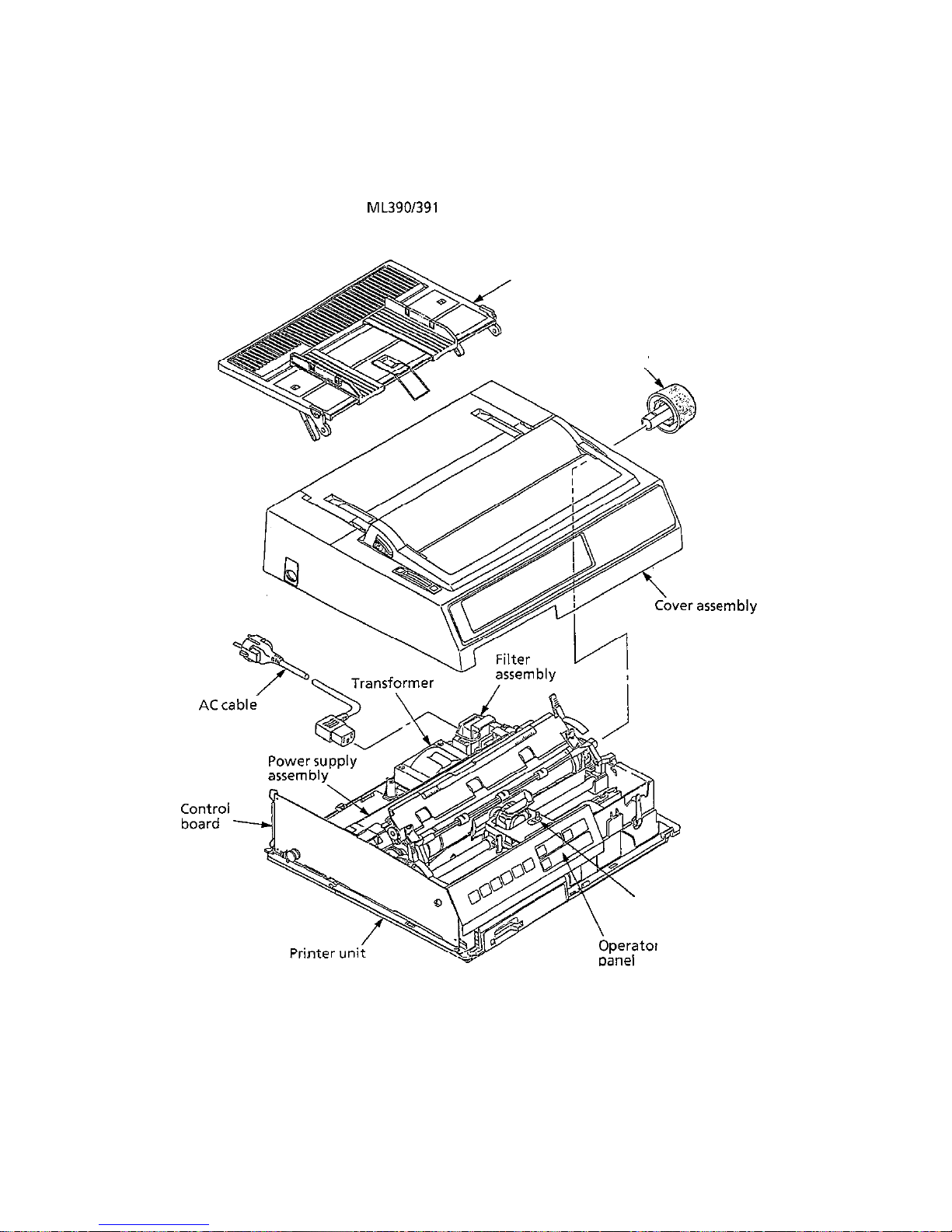
The standard configuration of the
ML390/391
Elite is as follows
py-
Platen knob
Paperseparator
\
Ribbon
cassette
perat
smbly
Figure l-l Printer configuration
l-l

1.2 Options
(1)
Tractorfeed unit with acoustic cover
(2)
Cut-sheet feeder unit with access
cover

(3)
Super-speed RS-232C serial interface board
(4)
Font memory card
l-3
1.3 Specifications
1.3.1 Print specifications
(1)
(2)
(3)
(4)
(5)
(6)
(7)
Print method
:
Number of dot wires
:
Dot wire diameter
:
Print direction
:
Impact dot matrix
24
0.0079 inch (0.2 mm)
Bidirectional, short-line-seeking printing
Unidirectional printing specifiable
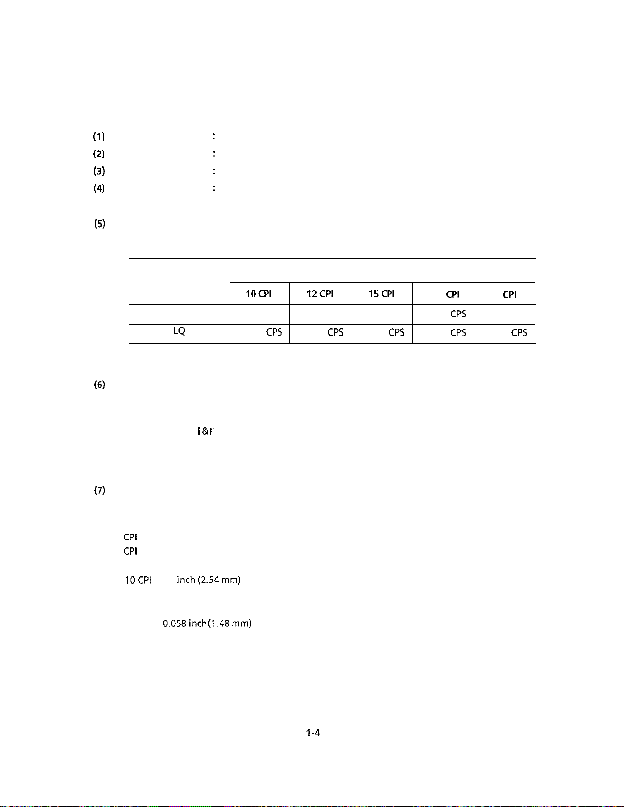
Print speed
Print mode
Utility
LQ
Character pitch
IOCPI
12CPI 15CPI
17.1
CPI
20
CPI
225.0 CPS
270.0 CPS 168.6 CPS
192.9
CPS
225.0 CPS
75.0
CPS
90.0
CPS
112.5
CPS
128.6
CPS
150.0
CPS
Character sets
Standard ASCII
EPSON Character Set
IBM Character Set I &
II
IBM Proprinter Compatible Character Set
Foreign Character Substitution
Line Graphics
Character pitches
The following character pitches are selectable through the operator panel* or with control
codes:
5
CPI
0.2 inch (5.08 mm)
6
CPI
0.167 inch (4.23 mm)
8.5 CPI 0.117 inch (2.96 mm)
* 1OCPI 0.1
inch(2.54mm)
* 12 CPI
0.083 inch (2.12 mm)
* 15 CPI
0.067 inch (1.69 mm)
* 17.1 CPI
0.058inch (1.48mm)
* 20 CPI
0.05 inch (1.27 mm)
1-4

1.3.2 Paper specifications
(1)
(2)
(3)
(4)
Cut-sheet paper
The standard size :
8-l/2
inches (wide) x 11 inches (long) for the U.S.
A4 size
:
210 mm
(wide) x
297 mm (long) for Europe
Weight
: 12 to 24 lb (45 to 90
g/mz)
Multiple-part paper cannot be used.
Sprocket paper
The tractor feed unit can handle sprocket paper of the following widths:
ML390 Elite: 3 to 10 inches (76.2 to 254 mm)
ML391 Elite: 3 to 16 inches (76.2 to 406.4 mm)
One-part paper
Ream weight: 12 to 24 lb (45 to 90 g/m*)
Multiple-part paper: 0.014 inch (0.356 mm) or lesstotal thickness
Number of sheets Ream
weig~ht
Number of sheets
Carbon-lined paper
Pressure-sensitive paper
interleaf paper
(paper)
(carbon)
9toll
lb
(35 to 40 g/m*)
IOtolZlb
(38 to 45
g/m2)
9lh
(35
glm2)
upto
including original
Upt04
including original
Multiple-part paper should be fastened by spot-pasting or crimping on both sides, and should
be free of wrinkles.
Cut envelope
Weight
:
Thickness
:
Size
24
Ibs
(90
glm2)
or less
0.016 inch (0.41 mm) or less
6-112x3-518
inches
8-718x3-718
inches
9-l/2
x4-118 inches
Multiple-part envelope
Weight
:
24
Ibs
(90
glmz)
or less
Thickness
:
0.014 inch (0.36 mm) or less
Width
:
3 to 10 inches (76.2 to 254 mm)
Medium feed :Bottom paper feed only
I-5
(5) Card
Weight
:
100
Ibs
(162.8
g/m2)
or less
Thickness
:
0.008 inch (0.20 mm) or
less
Size
:
5 x 8 inches (when cut apart)
Medium feed :Bottom paper feed only
(6) Label
Thickness
:
0.011 inch (0.28 mm) or less
Size
:
ML390 Elite-8.5x3.25
inches(216x83
mm) or less
ML391 Elite- 15x3.25 inches(381 x 83 mm) or
less
(7)
OHP sheet (transparencies)
Thickness
:
0.004 inch (0.10 mm) or less
Size
:
8.5 x 11 inches (216 x 280 mm) or less
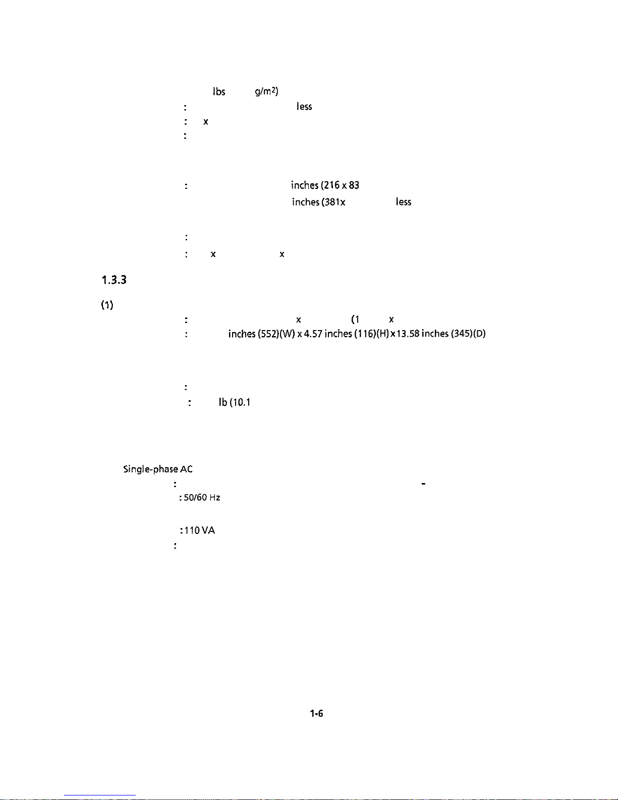
1.3.3
Physical specifications
(1)
Outside dimensions
ML390 Elite
:
15.67 inches (398)(W) x 4.57 inches (I 16)(H) x 13.58 inches (345)(D)
ML391 Elite :21.73
inches(552)(W)x4.57inches(l16)(H)
x 13.58inches(345)(D)
These dimensions do not include the platen knob, acoustic cover and paper separator,
(2) Weight
ML390 Elite :18.5 lb (8.4 kg)
ML391 Elite : 22.3 lb(10.1 kg)
1.3.4 Power requirements
(1) input power
Single-phaseAC
Voltage
:
One of the following as specified: 2201240 VAC + 10% - 10%
Frequency : 50/60Hz + 2%
(2) Power consumption
Operating :
IlOVA
Idle
:
40VA
l-6
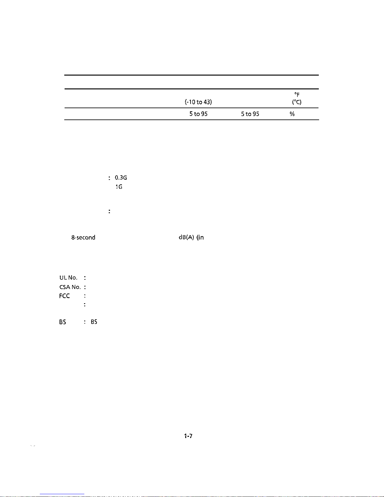
1.3.5 Environmental conditions
(1)
Ambient temperature and relative humidity
Operating Non-operating
Storage
Unit
Temperature
Relative Humidity
41to104
14to
109.4
-40to158
(5 to 40)
(-lOto43)
(-40 to 70)
20 to 90
5to95 5to95
%
RH
The printer must be packed during storage
Avoid condensation at all times.
(2) Vibration
Operating
:
0.3G
(5 to 150 Hz) or less (except the unit is resonant frequency)
Non-operating :1G (5 to 150 Hz) or less (except the unit is resonant frequency)
(3)
Impact (Drop test)
Packing
:
30” (One corner and three edges and all six sides)
1.3.6 Noise
The
8-second
average noise is less than 57
dB(A)(’In
all mode), 52 dB(A) (in quiet mode) when
measured under the above conditions with the printer fitted with the acoustic cover.
1.3.7 Agency approvals
ULNo.
:
CSANo. :
FCC
:
VDE
:
B5
:
The printer is listed in UL STANDARD No. 478.
CSA certification to CSA STANDARD C22.2 No. 220
FCC certified per Part 15, SUBJECT J, CLASS B.
VDE 0806.
VDE 0871 Class B.
ES
5850
I-7

2. INSTALLATION PROCEDURE

2. INSTALLATION PROCEDURE
2.1 Unpacking
2.1.1
Unpacking the packing box
(1) Unpackthepackingbox.
(2) Takeouttheprinterunit.
(3) Takeouttheaccessories.
Packing box
2-1
.
,’

2.1.2
Unpacking the printer unit
(1)
Removethe printer unit from the polyethylene bag.
Polyethylene bag
Printer unit
2-2

2.1.3
Unpacking the accessories
(1)
Remove the AC cable, fuses, paper separator, platen knob, ground screw, and ribbon cassette
from the polyethylene bag.
Paperseparator
Polyethylene bag
Ribbon cassette
Platen kno6
2-3
2.2 Installation (Refer to the User’s Manual for Details.)
2.2.1 Precaution for installation
Pay attention to the following when installing the printer:
(1)
(2)
(3)
(4)
Do
not install the printer in the following places:
CL/
W
w
Cd)
(4
(0
(cd
Any place exposed to direct sunlight.
Any place with great fluctuations in temperature.
Any place exposed to outdoor wind.
A dusty place
Near a door
Near an air-conditioner.
Any place with heavy vibrations.
DO
not smoke in the area where the printer is installed.
Adjust the temperature and humidity of the installation site as follows:
Temperature
:
41 to 104°F (5 to 40°C)
Humidity
: 20to90%
RH
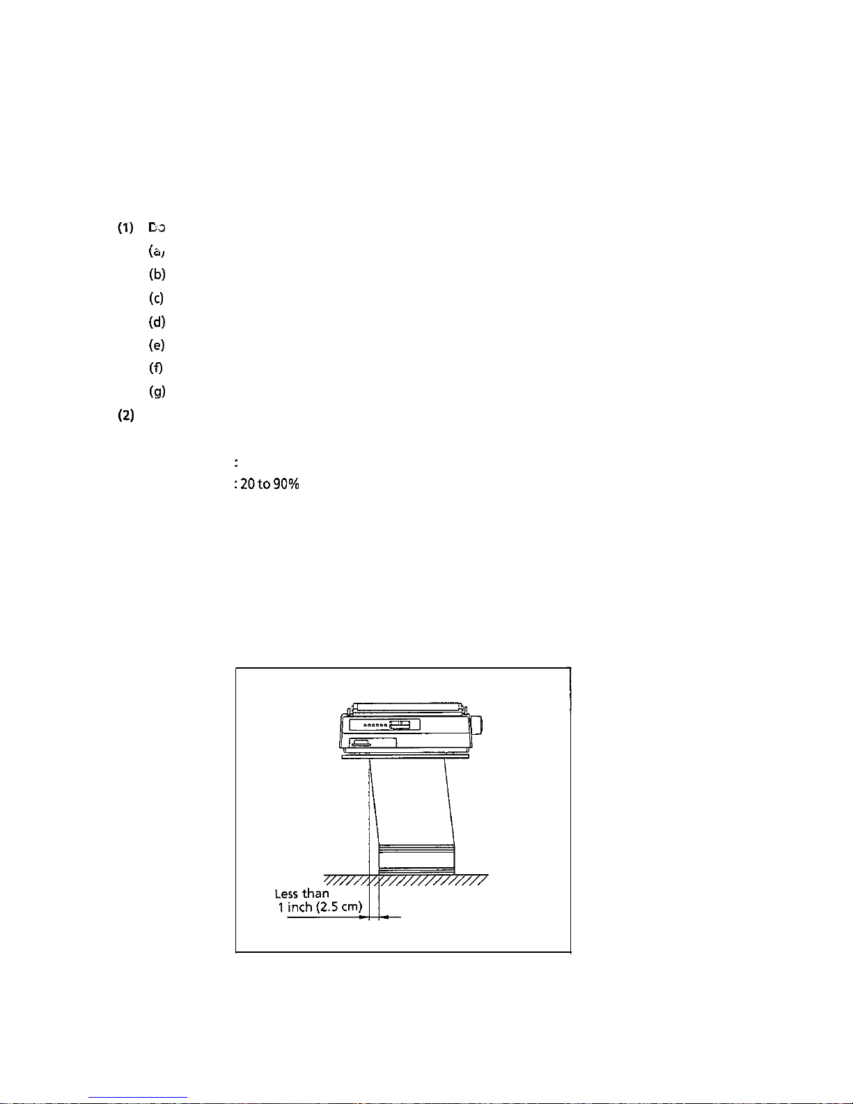
Place the printer and continuous
form
in the following procedure:
1) The height of the desk for the printer is 28 inches (70 cm) standard.
(Install the printer on a level and flat desk or stand so that its four rubber feet fit flatly on
the surface.)
2) Paper positioning
Place forms in parallel with the paper feed path.
The positioning tolerance of the left and right direction should be less than 1 inch (2.5 cm).
2-4
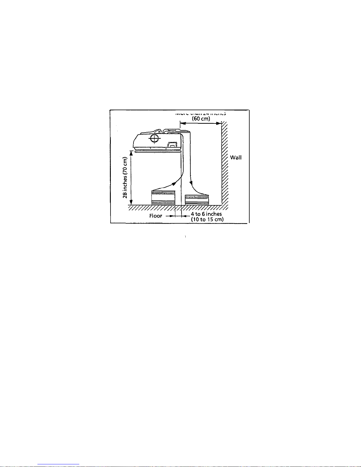
3) Printer rear space requirement
Match the rear part of the printer with the edge of a desk.
Leave a space of more than 24 inches (60 cm) at the rear of the printer to allow sufficient
space for paper.
4) To prevent incoming and outgoing forms from interfering with each other, place the forms
within 4to 6 inches (10 to 15 cm) from the edge of a desk.
Paper
jamming
may occur if forms interfere with each other.
More than 24
inches
2-5

2.2.2 Removing the shipping retainer
Remove the shipping retainer which secures the printhead from movement during shipping by
opening the access cover.
Shipping retainer
R
2-6

2.2.3 Installing the accessories
(1)
Install the sheet separator.
(2)
Install the platen knob.
(3)
Install the ribbon cassette.
,
Sheet separator
knob
Ribbon cassette
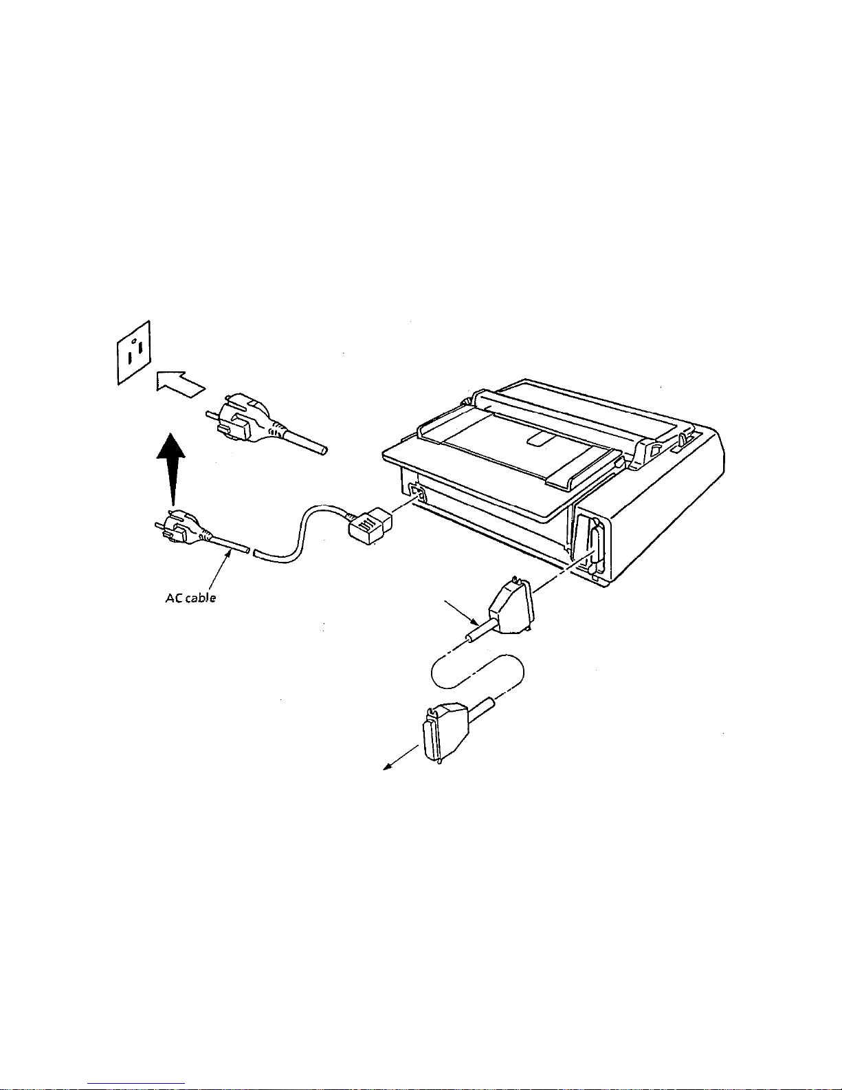
2.2.4 Connecting cables
(1)
Connect the interface cable,
(2)
Connect the AC cable.
Make sure that the AC power switch on the right side of the printer is set to OFF side (the side
marked with 0).
Interface cable
To the host computer
2-8

2.2.5
installing paper
Install
continbous
form~paper to test the unit. (Refer to User’s Manual for Details).
2-9

2.2.6 Powering on
(1)
Push the AC “POWER” switch on the right side of the printerto “ON” (the side marked with I)
(2)
Confirm that the “POWER” lamp goes on and the printhead returns to its home position.
2-10

2.2.7 Rolling ASCII test pattern
(1)
Confirm
thatthe
“POWER” switch is OFF and while pressing the
“TOF/QUIET”
switch, press the
“POWER” switch to “ON”.
(2)
The rolling ASCII pattern as shown below will be printed.
(3)
To finish the test, press the “MODE” switch.
(4)
The
“SEL”
lamp will go on, indicating that the printer unit is ready to receive printing data
from the host computer.
2.11

3. THEORY OF OPERATION

3. THEORY OF OPERATION
3.1 Electrical Operation
This
secti,on de~scribes
the electrical operation of the printer circuits.
3.1.1
General
The block diagram of the printer circuit is shown in Figure 3-1.
The control board consists of the microprocessor and its peripheral circuits, the drive circuits, paper
end sensor and interface connector.
The power to the control board is provided from the power supply board via the connector cord.
The power to the other electrical parts is distributed via the connectors in the control board.
3.1.2 Microprocessor and its peripherals circuits
(1)
Microprocessor(Q8: 8OC154)
The microprocessor is the nucleus of the control circuit. Its peripheral circuits operate under
program control by this microprocessor. The
110
ports of the microprocessor are connected to
the address bus, data bus, and control lines.
(2) Program ROM (Q12)
The program ROM contains the control program for the printer. The microprocessor operates
by execution of this control program.
(3)
RAM
(Ql
and
92); (93
and
44)
are option.
The RAM stores data such as print data which has been received.
3-1

(4) LSI (MSM6990)
(911)
The MSM6990 is an external interface and motor control
LSI.
It has the following functions:
A: External interface controller
(a) Parallel interface function
The parallel interface function mode is selected when the level of the mode selection signal
(ISEL) is high. In this mode, IFDl to
IFD8
are used as an input port; the parallel data received
through the interface connector is latched in synchronization with the strobe signal
(STB)
and is sent to the CPU in synchronization with the RD signal. In this mode, the MSM6990
also sends BUSY, ACK, PE and SELECT signals to the parallel interface connector in
synchronization with the WR signal.
(b)
Serial interface function
The (ISEL) signal goes low and the serial interface function mode is selected only when the
serial interface board is installed. In this mode,
IFDl
to IFD8 are used as an input port;
parallel data received from the serial interface board is sent to the CPU in synchronization
with the RD signal. In this mode, the MSM6990 sends SSD, RTS, and DTR signals to the serial
interface connector in synchronization with the WR signal.
(c) I/O
ports
The MSM6990
(Qll)
has a
12-bit
output port and a
lo-bit
input port. It sends control signals
in accordance with the commands from the microprocessor.
The input port is also used to read information from the operation panel switches, etc.
(d)
Address latch
The address latch latches the low-order 8 bits of the address bus (A0 to
A7).
These bits are
used as an address for read/write operations with peripheral devices. Latching of (A0 to A7)
is necessary because these 8 bits are also used as the data bus.
8: Motor controller
(a)
Spacing speed control function
This function accelerates and decelerates the spacing motor in accordance with commands
from the microprocessor and controls the spacing motor speed in each printing mode.
(b)
Dot timing generation function
This function generates the dot-on timing signal
(IPT),
synchronized with the printing speed
in accordance with output
signab
(PHASE A, 8) of the encoder disk on the spacing motor,
and sends this timing information to the microprocessor.
(5) CGROM
(Q5)
The resident character fonts are stored in the character generator.
3-2

(6) EEPROM
(Q9)
This
256-bit
serial data electrically erasable and programmable ROM stores the menu mode
data.
(7)
LSI
(MSM79H097) (46)
The MSM79H097 controls the DMA, head drive and LF microstep. The details are described
below.
(a) DMA control
Data transfers from ROM to D-RAM or between
D-RAMS
is performed by DMA transfer
eliminating the need of the CPU to perform such operations.
By setting the address of the transfer origin, the transfer destination and the number of
bytes to be transferred and starting from the CPU, data in memory can be transferred
directly.
(b)
Head drive control
Drive pulses are produced for impact timing of the head using IPT signals as triggers. IPT
signals are generated by phase A and B signals from the spacing motor.
The pulse width of this drive differs according to the number of the impact pins.
Its duration
can be preset by the CPU.
(c)
Print data transfer control
Performs the serial transfer control of print data.
Print data will be transferred automatically from the memory area stored for decoding to
the register in this LSI in synchronization with an IPT signal coming from MSM6990.
The data which is stored in the register will be transferred to the head drive unit as serial
data just before the next impact timing.
(d)
LF micro step control
Performs micro step control to enable fine feed of the LF motor.
(e)
Memory interface
This function expands the memory space for ROMs and
RAMS
which are connected to this
LSI,
and makes it possible for the memory to access 368 Kbytes.
(0 D-RAM refresh
Performs refreshing of D-RAMS using the CAS before RAS refresh method.
3-3
 Loading...